

Page 1
Product Bulletin
8532 Valve
D101552X012
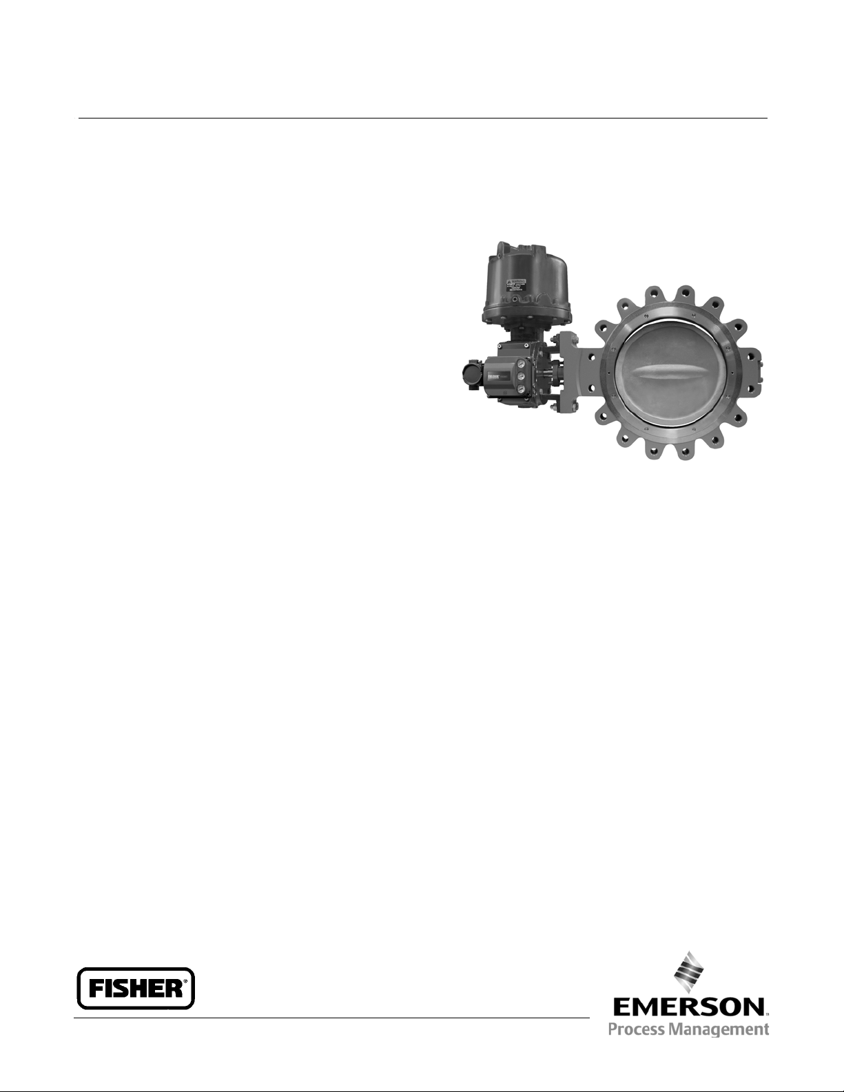
Fisherr 8532 High-Performance Butterfly
Valve
The Fisher 8532 high-performance butterfly valve
provides outstanding performance under extreme
pressure and temperature conditions. The 8532 valve
maintains tight shutoff, is available in a fire-tested
version, and can be specified for cryogenic
applications.
The 8532 valve is available as either a flangeless,
wafer-style design or as a single-flange (lugged)
design. A splined drive shaftcombineswithavarietyof
spring-and-diaphragm or pneumatic piston actuators
to make the 8532 a reliable, high-performance
butterfly valve for a variety of throttling and on-off
applications in the various process industries.
The8532valvecanbesuppliedwithoneofseveral
dynamic seals (figure 4) that can be used in a variety of
demanding applications. With the appropriate seal
selection and materials of construction, the
pressure-assisted seal provides excellent shutoff
against the full CL150 or CL300 pressure ratings.
Unless otherwise noted, all NACE references are to
NACE MR0175-2002.
W9138-2
Economically Designed for Minimal Deadband–A
splined end connection on the drive shaft allows
lever clamping by most Fisher rotary actuators.
Application Versatility–Standard construction
materials and seal assemblies provide long life and
outstanding performance in a broad range of liquid
and gas applications.
51.6:8532
April 2013
Features
Economical Tight Shutoff–The pressure-assisted
seal design provides tight shutoff against the full
pressure rating of the specified valve.
Safety–Shaft blowout protection is designed into
the8532valve(figure6).Theanti-blowout gland
fits securely over the valve shaft which has been
turned down to form a circumferential shoulder
that contacts the anti-blowout gland.
Excellent Flow Control–With a modified equal
percentage flow characteristic, the 8532 can be
used for throttling applications through 90 degrees
of disc rotation. Rangeability is 100 to 1.
Ease of Maintenance–Interchangeability of all parts
including shafts and discs simplifies service and
reduces maintenance costs.
Improved Environmental Capabilities– The optional
ENVIRO-SEALpackingsystemisdesignedwithvery
smooth stem surfaces and live-loading provides
improved sealing, guiding, and loading force
transmission. The ENVIRO-SEAL packing system can
control emissions below the EPA (Environmental
Protection Agency) limit of 100 ppm (parts per
million).
Easy Installation–The valve body self-centers on the
line flange bolts as a fast, accurate means of
centering the valve in the pipeline.
Reliable Flange Gasketing Surface–Seal retainer
screws are located so there is no interference with
the sealing function of either flat sheet or spiral
woundlineflangegaskets.
www.Fisher.com
Page 2

Product Bulletin
51.6:8532
April 2013
Specifications
8532 Valve
D101552X012
Available Valve Configurations
J Flangeless, wafer-style or J single-flange (lugged)
controlvalvewithaone-piece valve body, a
two-component seal/backup O-ring, and a splined
drive shaft
Valve Body Sizes
NPS J 14, J 16, J 18, J 20, and J 24
End Connection Style
J Flangeless, wafer-style or J single flange valve
body designed to fit between raised-face mating
flanges per ASME B16.5 CL150 or CL300
Maximum Inlet Pressure/Temperature
(1)
Consistent with J CL150 and J CL300
pressure/temperature ratings per ASME B16.34. Also,
see figures 2 and 3 for additional information
Available Seal Configurations
Standard Constructions
Seefigure4andtable2
Standard Construction Materials
Valve Body and Disc: ASTM grades of J carbon steel
or J stainless steel
Disc Coating:
Hardcoating (also see table 2): J Standard when used
with NOVEX seal, J Phoenix III seal, or J Cryogenic
seal
Chromium Carbide: Standard when service
temperature exceeds 538_C (1000_F)
Shaft: ASTM grade of J S17400 (17-4PH H1025 SST),
J S17400 (17-4PH H1150M SST), or J S20910
Shaft Extension Lengths:
High Temperature J None required for temperatures
less than 343_C(650_F),
J 6 inches for temperatures from 343 to 538_C(650
to 1000_F), or J 12 inches for temperatures above
538_C (1000_F)
Cryogenic J 914mm (36 inches)
Seal Ring: J PTFE, J S31600 (316 SST), J S21800,
J S31600/PTFE, J UHMWPE
(4)
,orJ CTFE
(5).
Backup ring: J Nitrile, J Chloroprene, J PTFE,
J Fluorocarbon--for a broad range of hydrocarbon
and chemical process applications
process applications including steam and water
(1)
or J EPR--for
(1)
backup ring is not used with the NOVEX seal
Packing: J PTFE V-ring (standard packing),
J Graphite (optional), or J ENVIRO-SEALt
packing (optional)
Bearings: J PEEK
.
(2)
(standard material), and
J S31600, J PTFE Composition, or J CoCr-A(Alloy
6) (optional)
Valve Body Classification
Face-to-face dimensions are in compliance with MSS
SP68 and API 609 standards; valve bodies are
designed for installation between ASME B16.5 CL150
or CL300 raised-face flanges
Shutoff Classification. Per ANSI/FCI 70-2and
IEC 60534-4
Standard Soft Seal: Bidirectional bubble-tight shutoff
NOVEX Seal: Unidirectional shutoff
1% of Class IV (preferred flow direction only
(3)
),
optional Class VI
Phoenix III Seal: Bidirectional bubble-tight
Phoenix III Seal for Fire Tested Applications: Class VI
shutoff. Contact your Emerson Process Management
sales office for more information.
Flow Characteristic
Modified equal percentage
Flow Coefficients
See table 1 and Fisher Catalog 12
Noise Levels
See Catalog 12 for sound pressure level prediction
Available Actuators
J Spring-and-diaphragm, or J pneumatic piston
.A
(continued)
2
Page 3
8532 Valve
D101552X012
Specifications (continued)
Product Bulletin
51.6:8532
April 2013
Disc Rotation
Clockwise to close
ENVIRO-SEAL Packing
This optional
J PTFE or J graphite packing system
provides improved sealing, guiding, and transmission
Valve Dimensions and Approximate Weights
See figures 7, 8, 9 and 10
1. The pressure/temperature limits in this bulletin (figures 2 and 3), and any application code or standardlimitation, should not be exceeded.
2. PEEK stands for poly-ether-ether-ketone.
3. For optimumseal performance, thepreferred valve orientationat shutoff is with the retaining ring downstream from the high pressure side of the valve.
4. UHMWPE standsfor ultra highmolecular weight polyethylene.
5. CTFE not recommended for fast cycling, less than 2 seconds.Contact your Emerson Process Management sales office for other seals available for fast cycling or tighter shutoff.
of loading force to control liquid and gas emissions.
See Bulletin 59.3:041 ENVIRO-SEAL Packing Systems
for Rotary Valves for more information.
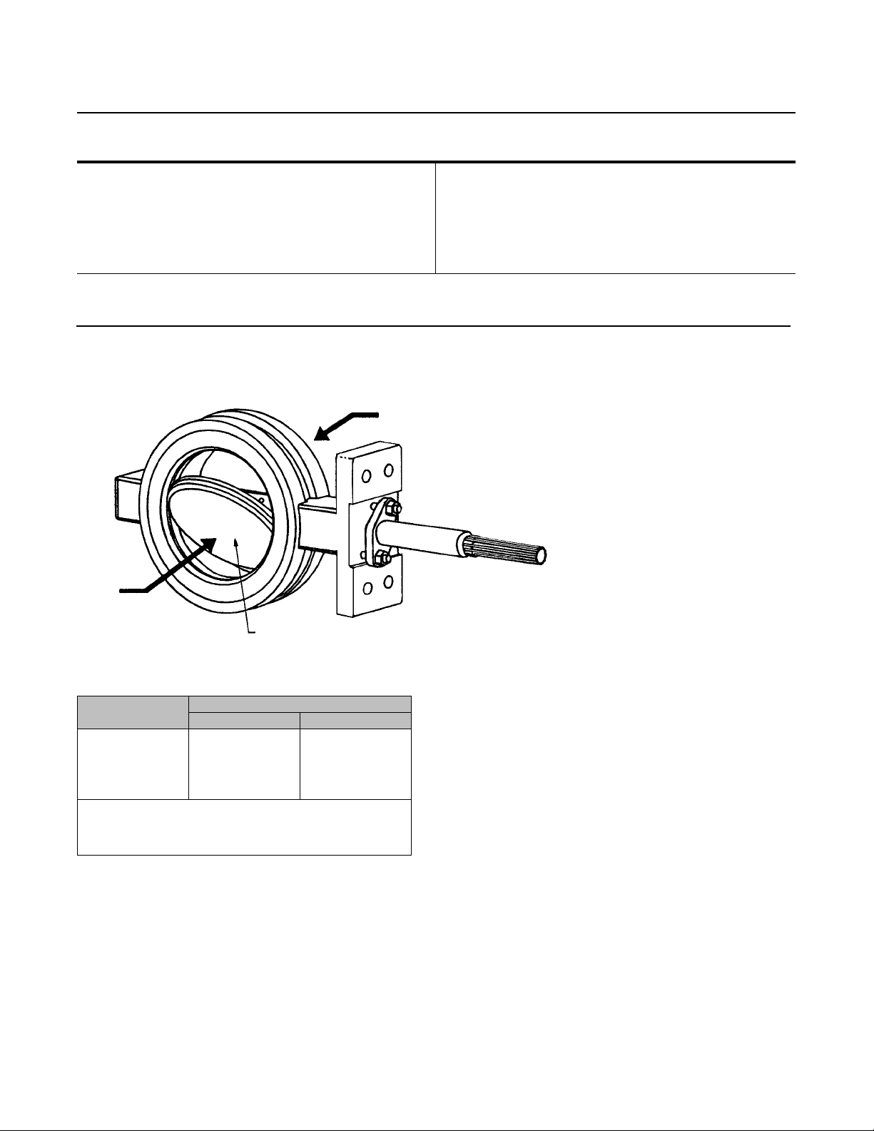
Figure 1. Flow Direction
REVERSE
FLOW (NORMAL FLOW DIRECTION)
FORWARD
FLOW
A7092
Table 1. Flow Coefficients
VALVE SIZE,
NPS
14
16
18
20
24
1. To obtain the flow coefficient Kvin terms of cubic meters per hour at one kilogram
force per square centimeter differential pressure across the valve, usingthe following
multiplier: K
2. Measured in gallons per minutes at 1 psi differential pressure across the valve.
3. See the section titled Coefficients in this bulletin, and also Catalog 12 for a
complete listing of flow coefficients.
=0.856Cv.
v
FACE SIDE OF DISC
(1)(3)
(2)
MAX C
CL150 CL300
6320
8600
11,050
13,850
21,500
, VALVE 90_ OPEN
v
4550
5630
8230
9530
12,510
Installation
Recommended installation for the 8532 valve is with
the shaft horizontal in a normal-flow direction.
Horizontal installation will enhance valve performance
because process fluid flow will sweep entrained solids
from valve surfaces. This sweeping action prevents
particle buildup on seal surfaces. However, the valve
may be installed in either the forward or reverse flow
direction.
The standard soft seal offers bubble-tight, bidirectional
shutoff. To meet the performance requirements of
many of today's fire-tested requirements, a Phoenix III
valvemustbeinstalledinthepreferredvalve
orientation. Both the NOVEX and cryogenic seals are
uni-directional and should be installed with the shaft
upstream of the seal.
Unique operating conditions may require a specific
combination of actuator motion. To satisfy unique
operating requirements, the valve and actuator can be
assembled in eight ways, providing for actuator
motion and open disc position. For assistance in
selecting the appropriate combination of actuator
action and open valve position, consult your Emerson
Process Management sales office.
Dimensions and weights for wafer-style and
single-flange valves are shown in figures 7, 8, 9 and 10.
3
Page 4
Product Bulletin
51.6:8532
April 2013
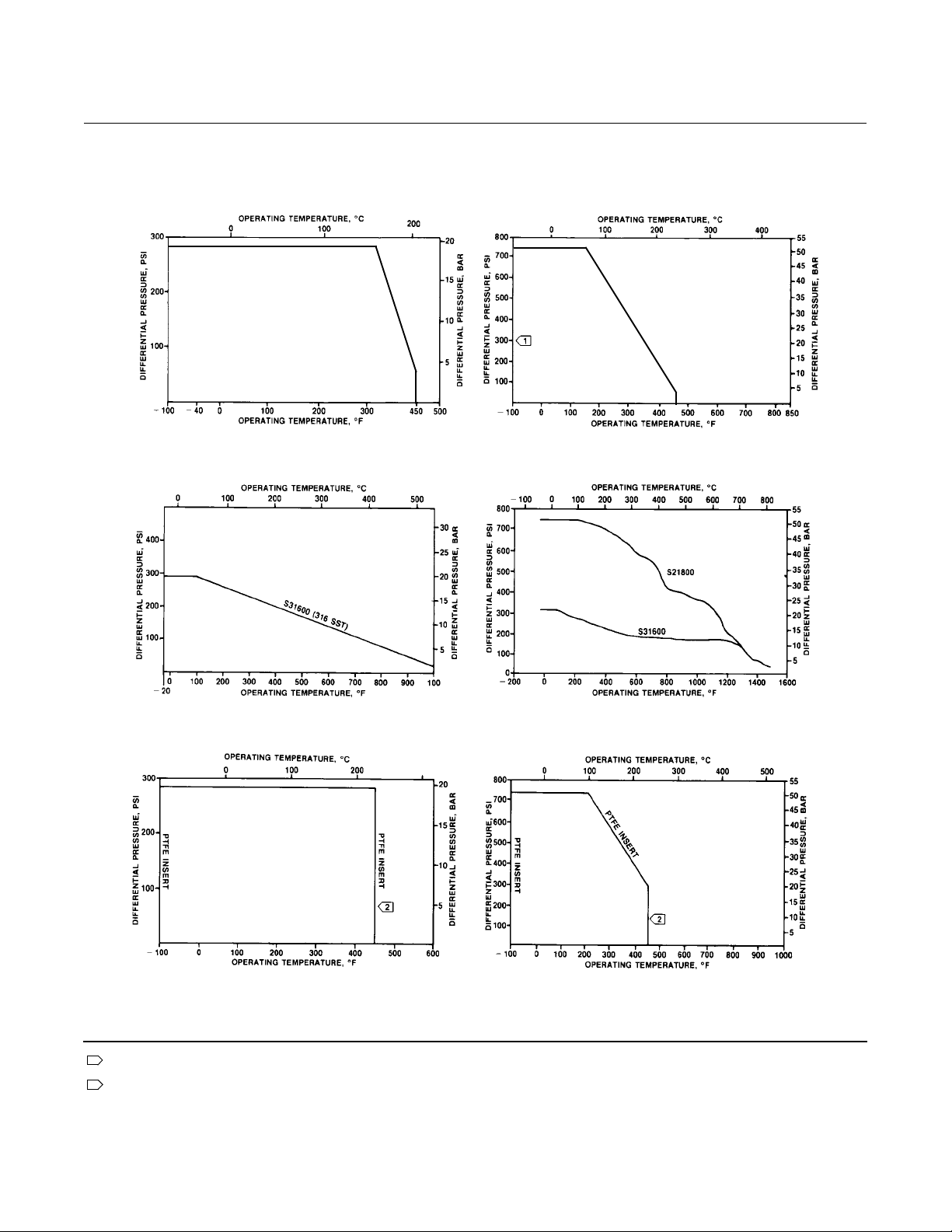
Figure 2. Maximum Pressure/Temperature Ratings for Soft Seal, NOVEX Seal and Phoenix III Seal, CL150 and CL300
8532 Valve
D101552X012
CL150 SOFT SEAL
CL150 NOVEX SEAL
CL300 SOFT SEAL
CL300 NOVEX SEAL
CL150 PHOENIX II SEAL
C0759-1
Note
1
Becauseof potential erosive effects andpremature seal failure thatcan occur, throttling PTFE seals at differential pressures greater than 300 psidat diskangleslessthan
20 degrees open is not recommended.
2
Temperature limitations do not account forthe additional limitations imposed by thebackup O-ring usedwith this seal. Todetermine theeffective temperature limita
tion of the appropriate seal backup O-ring combination, refer to table 1.
4
CL300 PHOENIX II SEAL
Page 5
8532 Valve
D101552X012
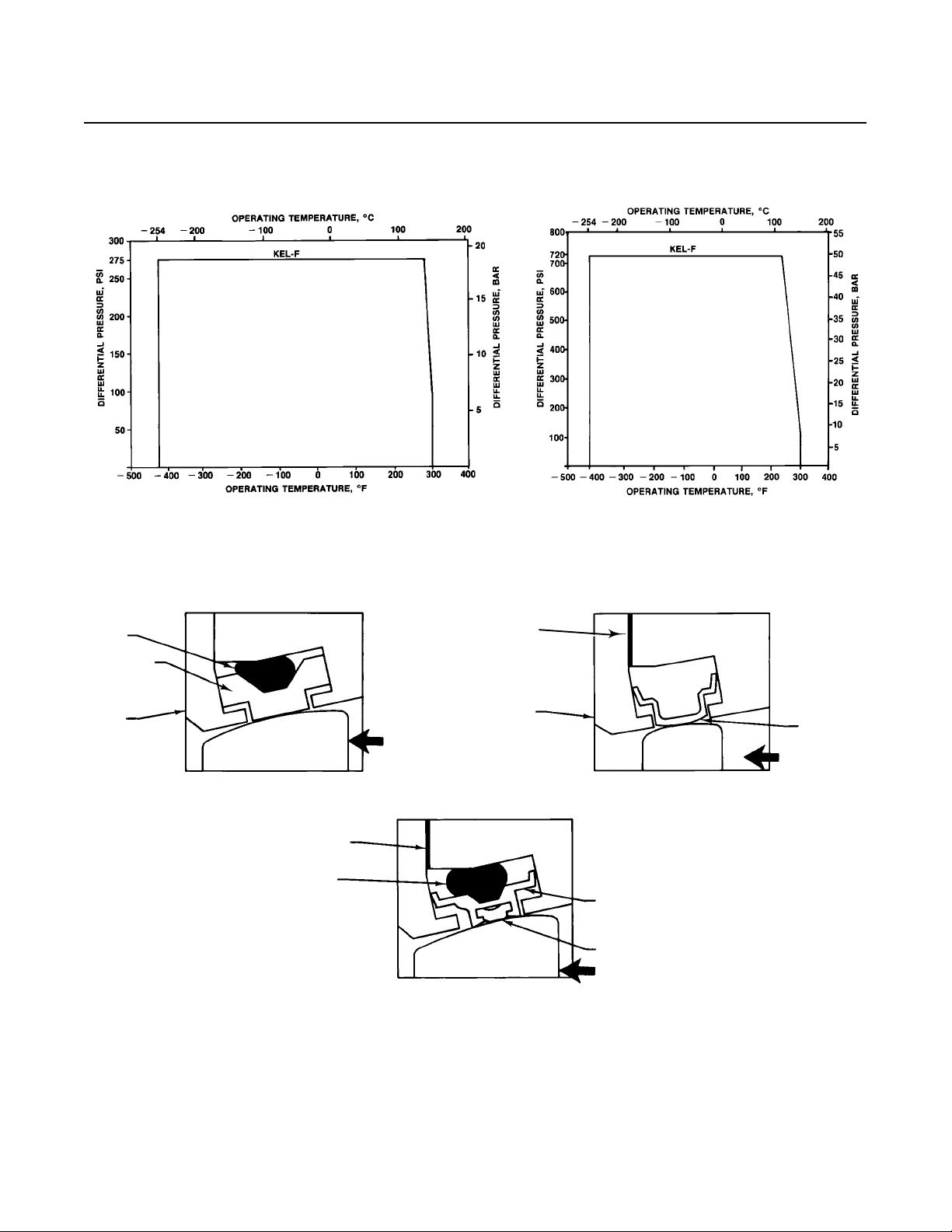
Figure 3. Maximum Pressure/Temperature Ratings for Cryogenic Seal, CL150 and CL300
Product Bulletin
51.6:8532
April 2013
B2336
CL150 CRYOGENIC SEAL
Figure 4. Available Seal Configurations
BACKUP
O-RING
SEAL RING
RETAINING
RING
PTFE OR UHMWPE SOFT
SEAL WITH BACKUP O-RING
B2313-2
BODY
VALVE DISK VALVE DISK
GRAPHITE
GASKET
BACKUP
O-RING
NORMAL
FLOW DIRECTION
(REVERSE FLOW)
VALVE DISK
PHOENIX III
FIRE SAFE SEAL
BODY
GRAPHITE
GASKET
RETAINING
RING
CL300 CRYOGENIC SEAL
BODY
NOVEX METAL SEAL
METAL
SEAL RING
RESILIENT
INSERT
NORMAL
FLOW DIRECTION
(REVERSE FLOW)
METAL
SEAL RING
NORMAL
FLOW
DIRECTION
(REVERSE
FLOW)
5
Page 6

Product Bulletin
51.6:8532
April 2013
8532 Valve
D101552X012
Figure 5. Typical Valve Assembly
SEEFIGURE3
THRUST BEARING
GASKET RETAINER
GASKET
DISC
DISC PINS
UPPER SHAFT
SEAT RETAINING RING
BEARINGS ANTI-BLOWOUT GLAND
THRUST
BEARING
ANTI-BLOWOUT FOLLOWER
PACKING FOLLOWER
A7093
Figure 6. Blowout Protection
PACKING
FLANGE
ANTIBLOWOUT
FLANGE
SHAFT SHOULDER
A7090
STANDARD PACKING ARRANGEMENT ENVIRO-SEAL ARRANGEMENT (PTFE SHOWN)
SHAFT
HEX NUT
STUD
HEX NUT
PACKING
FOLLOWER
TYPICAL PTFE V-RING
PACKING
VALVE BODY
HEX NUT
PACKING
FLANGE
SPRING PACK
ASSEMBLY
SHAFT
SHOULDER
ANTI-EXTRUSION
RING
STUD
LUBRICANT
HEX NUT
ANTIBLOWOUT
FLANGE
PACKING
SET
PACKING
BOX RING
6
Page 7

Product Bulletin
8532 Valve
D101552X012
Table 2. Material Temperature Ratings
COMPONENT AND MATERIAL OF CONSTRUCTION
Valve Body
(2)
Carbon Steel (WCC or SA 516-70)
(3)
FMS 20B16a Fisher material standard (0.04% min carbon) CL300
CF8M
CF8M (316SST) CL150and CL300
(1)
(7)
-198 to538
over 538 to 816
Disc
WCC carbon steel
(3)
FMS 20B16a Fisher material standard (0.04% min carbon) CL300
CF8M
CF8M (316SST)
-198 to538
over 538 to 816
Disc Coating
Chromium Carbide
Chrome Plating
Chromium Coating
Electroless Nickel Coating (ENC)
-198 to916
-254 to316
-254 to593
-254 to343
Shaft
S20910
-198 to538
S17400 (17-4pH 1025)
S17400 (17-4pH H1150M)
N07718
N07750
(6)
Bearings
PEEK (standard)
S31600
(4)
R30006 (Alloy6)
Bronze
-196 to427
-254 to704
over 593 to 816
-198 to816
-198 to816
-254 to302
Packing
PTFE Packing and PTFE ENVIRO-SEAL Packing
Graphite packing
Graphite packing with oxidizing media
Graphite ENVIRO-SEAL Packing
-148 to232
-198 to916
-198 to538
-148 to315
PTFE Seal Ring
Nitrile Backup O-Ring
Chloroprene Backup O-Ring
EPR Backup O-Ring
Fluorocarbon Backup O-Ring
PTFE BackupO-Ring
UHMWPE
Seal Ring and
Backup Ring
(5)
Seal Ring (CL150 Only)
Nitrile Backup O-Ring
Chloroprene Backup O-Ring
EPR Backup O-Ring
Fluorocarbon Backup O-Ring
PTFE BackupO-Ring
Phoenix III and/or Fire Tested Construction
S31600 and PTFE Seal Ring with Nitrile Backup O-Ring
Chloroprene Backup O-Ring
EPR Backup O-Ring
Fluorocarbon Backup O-Ring
(4)
Ring (CL150)
(4)
Ring (CL300)
(4)
Ring (CL300)
Seal Ring
NOVEX S31600Seal
NOVEX S31600Seal
NOVEX S21800Seal
Cryogenic Seal Ring Contact your Emerson Process Management sales office
1. NACE trim constructions areavailable; consult your Emerson Process Management sales office.
2. Special gasket retainer bolts are required for over 482_C(900_F)
3. Special retainingring screws for single flange valves over 538_C (1000_F)
4. For a complete materialdes cription, contact your Emerson Process Management sales office.
5. UHMWPE standsfor ultra high molecular weight polyethylene.
6. Special thrust bearings are required for hightemp. applications over 343_C(650_F) (with 6- and12-inch shaft extensions). Constructions withcarbon steel valves and SST discs may require
special thrust bearings at temperatures less than 343_C (650_F).
7. Cast or wrought /plate grades used interchangeably,depending upon availability - unless requested bycustomer.
TEMPERATURE RANGE
_C _F
-29 to 427
over 1000 to 1500
-29 to 427
over 1000 to 1500
-73 to 427
over 1100 to 1500
-73 to 260
-29 to 93
-43 to 149
-54 to 182
-29 to 204
-73 to 204
-29 to 93
-43 to 93
-54 to 93
-29 to 93
-73 to 93
-40 to 149
-54 to 149
-62 to 204
-40 to 232
-29 to 538
-29 to 816
-29 to 816
51.6:8532
April 2013
-20 to 800
-325 to1000
-20 to 800
-325 to1000
-325 to1500
-425 to600
-425 to1100
-425 to650
-325 to1000
-100 to800
-320 to800
-425 to1300
-100 to500
-325 to1500
-325 to1500
-425 to575
-325 to450
-325 to1500
-325 to1000
-325 to600
-20 to 200
-45 to 300
-65 to 360
-20 to 400
-100 to400
-20 to 200
-45 to 200
-65 to 200
-20 to 200
-40 to 200
-40 to 300
-65 to 300
-80 to 400
-100 to200
-20 to 1000
-20 to 1500
-40 to 1500
7
Page 8
Product Bulletin
51.6:8532
April 2013
Table 3. Dimensions and Weights, Wafer Style Valves, CL150
S
Valve Size,
NPS
14
16
18
20
24
14
16
18
20
24
1. Face-to-face dimensions are in compliance with MSS SP68 and API 609 specifications.
2. M is the minimum pipe or flange I.D. required fordisc swing clearance.
(1)
A
91.9
102
114
127
154
3.62
4.00
4.50
5.00
6.06
D G K M
208
208
356
356
356
8.19
8.19
14
141415.00
295
318
349
381
438
11.62
12.50
13.75
17.25
327
371
400
432
492
12.88
14.62
15.75
17.00
19.38
(2)
331
375
419
464
581
13.04
14.77
16.49
18.27
22.87
422
465
529
584
692
16.62
18.31
20.81
23.00
27.25
Figure 7. Dimensions and Weights, Wafer Style Valves, CL150 (also see table 3)
(Shaft Dia
R
at Yoke
Bearings)
mm kg
31.8
31.8
39.6
44.5
57.2
Inches Pounds
1-1/4
1-1/4
1-9/16
1-3/4
2-1/4
T U W Y
235
235
273
273
337
9.25
9.25
10.75
10.75
13.25
46.0
46.0
50.8
50.8
76.2
1.81
1.81
2.00
2.00
3.00
17.5
17.5
20.1
20.1
23.9
0.69
0.69
0.81
0.81
0.94
8532 Valve
D101552X012
---
28.6 4 holes
31.8 4 holes
31.8 4 holes
34.9 4 holes
---
1-1/8 4 holes
1-1/4 4 holes
1-1/4 4 holes
1-3/8 4 holes
Approx
Weight
72
94
139
167
255
158
207
307
368
563
C0729-1
8
Page 9

8532 Valve
D101552X012
Table 4. Dimensions and Weights, Single Flange Valves, CL150
S
Valve Size,
NPS
14
16
18
20
24
14
16
18
20
24
1. Face-to-face dimensions are in compliance with MSS SP68 and API 609 specifications.
2. M is the minimum pipe or flange I.D. required fordisc swing clearance.
(1)
A
91.9
102
114
127
154
3.62
4.00
4.50
5.00
6.061414
208
208
356
356
356
8.19
8.19
14
D G K M
295
327
318
371
349
400
381
432
438
492
11.62
12.50
13.75
15.00
17.25
12.88
14.62
15.75
17.00
19.38
13.04
14.77
16.49
18.27
22.87
331
375
419
464
581
(2)
531
607
645
696
822
20.88
23.88
25.38
27.38
32.38
Figure 8. Dimensions and Weights, Single Flange Valves, CL150 (also see table 4)
(Shaft Dia
R
at Yoke
Bearings)
mm kg
31.8
31.8
39.7
44.5
57.2
Inches Pounds
1-1/4
1-1/4
1-9/16
1-3/4
2-1/4
T U W Y
235
235
273
273
337
9.25
9.25
10.75
10.75
13.25
46.0
46.0
50.8
50.8
76.2
1.81
1.81
2.00
2.00
3.00
14.2
14.2
20.1
20.1
23.9
0.56
0.56
0.81
0.81
0.94
Product Bulletin
51.6:8532
April 2013
Approx
Weight
---
---
---
---
---
1-812Holes
1-816Holes
1-1/8-816Holes
1-1/8-820Holes
1-1/4-820Holes
95
138
178
224
315
209
304
393
493
773
C0730-1
9
Page 10

Product Bulletin
51.6:8532
April 2013
Table 5. Dimensions and Weights, Wafer Style Valves, CL300
S
Valve Size,
NPS
14
16
18
20
24
14
16
18
20
24
1. Face-to-face dimensions are in compliance with MSS SP68 and API 609 specifications.
2. M is the minimum pipe or flange I.D. required fordisc swing clearance.
(1)
A
117
133
149
159
181
4.62
5.25
5.88
6.25
7.12
D G K M
356
356
356
265
546
14
14
14
10-7/16
21-1/2
319
353
384
416
483
12.56
13.88
15.12
16.38
19.00
364
397
419
483
546
14.31
15.62
16.50
19.00
21.50
304
346
389
442
523
12
13.6
15.3
17.4
20.6
(2)
437
498
556
605
716
17.19
19.62
21.88
23.81
28.19
Figure 9. Dimensions and Weights, Wafer Style Valves, CL300 (also see table 5)
(Shaft Dia
R
at Yoke
Bearings)
mm kg
44.5
44.5
57.2
76
76
Inches Pounds
1-3/4
1-3/4
2-1/4
3
3
T U W Y
273
273
337
337
337
10.75
10.75
13.25
13.25
13.2533
50.8
50.8
76.2
76.2
76.2
2
2
3
20.6
20.6
23.9
23.9
23.9
0.81
0.81
0.94
0.94
0.94
8532 Valve
D101552X012
---
---
---
---
---
1-1/8-84Holes
1-1/4-84Holes
1-1/4-84Holes
1-1/4-84Holes
1-1/2-84Holes
Approx
Weight
121
183
227
364
469
266
403
500
802
1035
10
B2352
Page 11
8532 Valve
D101552X012
Table 6. Dimensions and Weights, Single Flange Valves, CL300
S
Valve Size,
NPS
14
16
18
20
24
14
16
18
20
24
1. Face-to-face dimensions are in compliance with MSS SP68 and API 609 specifications.
2. M is the minimum pipe or flange I.D. required fordisc swing clearance.
(1)
A
117
133
149
159
181
4.62
5.25
5.88
6.25
7.12
D G K M
356
356
356
265
546
14
14
14
10-7/16
21-1/2
319
353
384
416
483
12.56
13.88
15.12
16.38
19.00
364
397
419
483
546
14.31
15.62
16.50
19.00
21.50
304
346
389
442
523
12.0
13.6
15.3
17.4
20.
(2)
594
657
721
784
924
23.38
25.88
28.38
30.88
36.38
Figure 10. Dimensions and Weights, Single Flange Valves, CL300 (also see table 6)
(Shaft Dia
R
at Yoke
Bearings)
mm kg
44.5
44.5
57.2
76
76
Inches Pounds
1-3/4
1-3/4
2-1/4
3
3
T U W Y
273
50.8
273
50.8
337
76.2
337
76.2
337
76.2
10.75
10.75
13.25
13.25
13.2533
Product Bulletin
51.6:8532
April 2013
Approx
Weight
20.6
20.6
23.9
23.9
23.9
2
0.81
2
0.81
3
0.94
0.94
0.94
---
---
---
---
---
1-1/8-816Holes
1-1/4-820Holes
1-1/4-824Holes
1-1/4-824Holes
1-1/2-824Holes
227
294
402
544
821
500
649
886
1200
1810
B2353
11
Page 12

Product Bulletin
51.6:8532
April 2013
8532 Valve
D101552X012
Neither Emerson, Emerson Process Management, nor any of their affiliated entities assumes responsibility for the selection, use or maintenance
of any product. Responsibility forproper selection, use,and maintenanceof any product remains solely with thepurchaser and end user.
Fisher and ENVIRO-SEAL are marks owned by one of the companies in the Emerson Process Management business unitof Emerson Electric Co.Emerson
Process Management, Emerson, and the Emerson logo are trademarks and service marks of Emerson Electric Co. All other marks are the property of their
respective owners.
The contents of this publication are presented for informational purposes only, and while every effort has been made to ensure their accuracy, they arenot
to be construed as warranties or guarantees, express or implied, regarding the products or services described herein or their use or applicability. All sales are
governed by our terms and conditions, which are available upon request.We reservethe right to modify or improve the designs or specifications ofsuch
products at any time without notice.
Emerson Process Management
Marshalltown, Iowa 50158 USA
Sorocaba, 18087 Brazil
Chatham, Kent ME4 4QZ UK
Dubai, United Arab Emirates
Singapore 128461 Singapore
www.Fisher.com
E 1991, 2013 Fisher ControlsInternational LLC. All rights reserved.
12
 Loading...