

Page 1
Instruction Manual
D251400X012
8510B Valve (EMA)
Fisherr 8510B Eccentric Disc Control Valve
November 2011
(EMA
(1)
)
Contents
Introduction 1.................................
Scope of Manual 1.............................
Description 3.................................
Specifications 3...............................
Installation 3..................................
Maintenance 6.................................
Packing Maintenance 7.........................
Stopping Leakage 7........................
Replacing the Packing 8.....................
Replacing the Seal Ring 11......................
Replacing the Disc and Shaft Assembly
or the Bearings 12...........................
Actuator Mounting 17.........................
Parts Ordering 19...............................
Parts Kits 20...................................
ENVIRO-SEAL™ Packing System Retrofit Kits 20.....
ENVIRO-SEAL Packing System Repair Kits 20.......
Parts List 21...................................
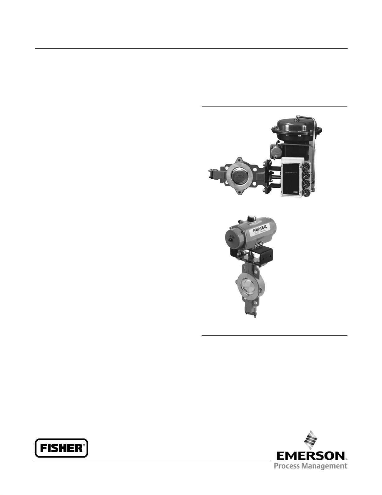
Figure 1. Fisher 8510B Eccentric Disc Control Valve
W4739-2
8510B CONTROL VALVE WITH FISHER 1052 ACTUATOR
AND 3610J POSTIONER
W8326
8510B VALVE WITH ALTERNATE DOUBLE D SHAFT WITH
ANTI-BLOWOUT AND FISHER 1035 ACTUATOR
Introduction
Scope of Manual
This instruction manual includes installation, maintenance, and parts information for NPS 2 through 12 Fisher 8510B
eccentric disc control valves that mate with ASME, EN, or JIS flanges (see figure 1). Refer to separate instruction
manuals for information covering the actuator and accessories.
www.Fisher.com
Page 2
8510B Valve (EMA)
November 2011
Table 1. Specifications
Instruction Manual
D251400X012
Valve Body Sizes and End Connection Style
For flangeless valves that install between ASME and
EN flanges, see table 2
Maximum Inlet Pressure
(2)
contact your Emerson Process Management sales
office with application limits
Disc Rotation
Clockwise to close (when viewed from actuator end
of valve body) through 90 degrees of disc rotation
Consistent with applicable ASME B16.34 or
EN 12516-1 ratings
Maximum Inlet Pressures, Temperatures, and
Pressure Drops
(1,2)
WCC Steel, CF3M Stainless Steel (316L SST), CN7M
(Alloy 20), and M35-1 Valve Bodies: Consistent with
applicable pressure-temperature ratings per table 2
up to the maximum material temperature capabilities
listed in table 3, but do not exceed the pressure,
temperature, and pressure drop conditions of the
valve construction. Also see the Installation section.
Actuator/Valve Action
With diaphragm or piston rotary actuators, they are
field reversible between:
J Push-down-to-open (extending actuator rod
opens the valve) and
J Push-down-to-close (extending actuator rod
closes the valve)
With 1035 Rack and Pinion actuator with spring
return or double acting action, field-reversible
between
J fail-to-open and J fail-to-close
Valve Body Classification
Shutoff Classifications
PTFE Seal Ring: Bidirectional shutoff to Class VI is
standard
All-Metal Seal Ring: 0.001% of maximum valve
capacity (one tenth of Class IV per ANSI/FCI 70-2 and
IEC 60534-4)
J ASME face-to-face dimensions for NPS 3 through 6
CL150 and 300, and face-to-face dimensions for NPS
8 through 12 CL150 meet API 609 standard
J Face-to-face dimensions for all sizes meet
EN 558 Series 25, and
J JIS B2210 standard face-to-face dimensions are
available upon request
Material Temperature Capabilities
See table 3
Flow Characteristic
Approximately linear
(1)
Mating Flange Capabilities
All sizes compatible with welding-neck and slip-on
flanges (schedule 80 or lighter for NPS 2 through 12)
Shaft Diameters
See table 2
Flow Direction
Standard (forward flow) is with seal retainer (key 2,
figure 8) facing upstream; reverse flow is permissible,
1. The pressure/temperature limits in this manual and any applicable standard or code limitation should not be exceeded.
2. The maximum allowable body inlet pressure might exceed the flange joint pressure rating. If so, actual inlet pressure must not exceed the flange joint pressure rating.
Approximate Weights
See table 2
Do not install, operate, or maintain 8510B valves without being fully trained and qualified in valve, actuator, and
accessory installation, operation, and maintenance. To avoid personal injury or property damage, it is important to
carefully read, understand, and follow all the contents of this manual, including all safety cautions and warnings. If you
have any questions about these instructions, contact your Emerson Process Management sales office before
proceeding.
2
Page 3
Instruction Manual
D251400X012
8510B Valve (EMA)
November 2011
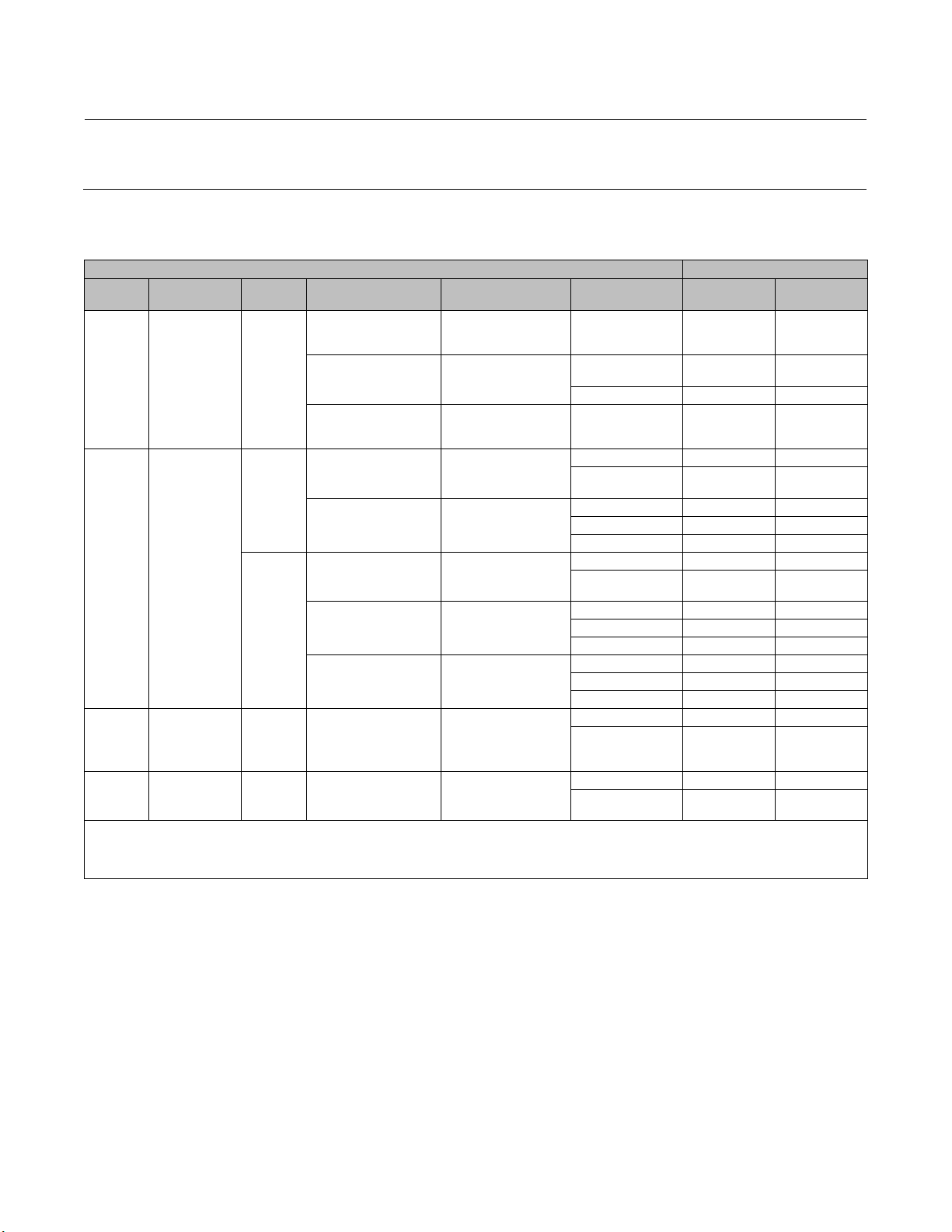
Table 2. Valve Body Size, Shaft Diameter, Approximate Weight, and ASME Rating and Flange Compatibility
VALVE
SIZE,
NPS
2
3
4
6
8
10 31.8 1-1/4 46 102
12 38.1 1-1/2 72 158
1. M35-1 valve materials are notincludedin ASME B16.34 pressure/temperature ratings. See table 3 for pressure/temperature information forM35-1valve bodies. The designations CL150,
CL300, and CL600 for thesevalve bodies are used only to indicate relativepressure-retaining capabilities and are not ASME pressure/temperature rating class designations.
2. The Double D end connection with anti-blowout s haft is only available in CL150.
3. The Double D end connection withanti-blowout shaft is available only in PN10 and PN16.
SHAFT
DIAMETER
mm Inches kg Pounds
12.7
1/2
15.9
5/8
19.1
3/4
25.4
31.8
1-1/4
1
APPROXIMATE
WEIGHT
4.3
5.9
9.1
19
31
9.5
13
20
41
69
ASME RATING
COMPATIBILITY–
STEEL, STAINLESS
STEEL, AND ALLOY 20
VALVE BODIES
CL150, 300, & 600
CL150
CL300
CL150
CL300
(2)
VALVE BODY
DESIGNATION–
(1)(2)
M35-1
CL150, 300, &
600
CL150
CL300
CL150
CL300
ASME FLANGE
COMPATIBILITY
CL150, 300, & 600
CL150
CL300
CL150
CL300
EN FLANGE COMPATIBILITY
(2)
PN10, PN16, & PN25
PN40, PN63, & PN100
PN10 & PN16
PN25 & PN40
PN10 & PN16
PN25 & PN40
(3)
Description
The 8510B flangeless control valve has an eccentrically mounted disc that self-centers in the line during installation.
The valve includes built-in electrical bonding of the shaft to the valve body. This valve has either a splined shaft for use
with power, handwheel, or handlever rotary actuators, or a double D end connection with anti-blowout shaft for use
with 1035 Rack and Pinion actuators and other quarter-turn actuators. It is used for throttling or on/off control of a
wide variety of liquids and gases. The 8510B is a balanced construction available in CL150 through 600. Figure 8
illustrates the various constructions.
Specifications
Specifications for the 8510B valve body are shown in table 1.
Installation
Key numbers in this procedure are shown in figure 8 unless otherwise indicated.
WARNING
Always wear protective gloves, clothing and eyewear when performing any installation operations to avoid personal
injury.
To avoid personal injury or property damage resulting from the bursting of pressure retaining parts, be c ertain the service
conditions do not exceed either the valve body rating or the flange joint rating, or other limits given in table 1 or on the
nameplate. Use pressure-relieving or pressure-limiting devices to prevent the service conditions from exceeding these
limits.
If installing into an existing application, also refer to the WARNING at the beginning of the Maintenance section in this
instruction manual.
CAUTION
The valve configuration and construction materials were selected to meet particular pressure, temperature, pressure drop,
and controlled fluid conditions specified in the customer's order. Because some valve body/trim material combinations are
3
Page 4
8510B Valve (EMA)
November 2011
Instruction Manual
D251400X012
limited in their pressure drop and temperature range capabilities (especially due to differences in thermal expansion rates),
do not apply any other conditions to the valve without first contacting your Emerson Process Management sales office.
Table 3. Material Temperature Capabilities
MATERIAL TEMPERATURE CAPABILITY
Valve
Body
Disc Shaft
WCC steel with
WCC steel
chrome-plated
seating surface,
or S31603
S17400
(17-4PH)
(316L SST)
S17400
S31603 (316L
SST) with
CF3M
(316L
stainless
steel)
M35-1
CN7M
(alloy 20)
1. For hot water or steam service, limit maximum temperature to 207_C (405_F).
2. Reinforced PTFE in phenolic resin. Emerson Process Managementdesignation is FMS 30B4.
3. PTFE with selected fillers. EmersonProcess Management designation is FMS 30B5.
4. For temperature limits of ENVIRO-SEAL packing systems, see the instruction manual Fisher ENVIRO-SEAL Packing System for Rotary Valves (D101643X012).
5. These materials are only available inthesplined shaft version of 8510B, and not in the double D end connection with anti-blowoutshaft.
chrome-plated
S31603 (316L
SST) without
with PTFE seat
(5)
(5)
CN7M (alloy 20)
surface or
plating
only)
S20910
M35-1 N05500
N08020
(alloy 20)
Bearing Lining and
Jacket
(2)
PTFE
/Composition
lined with S31603 (316L
SST) jacket
S44004 (440-C SST) All
metal bearing
(2)
PTFE
/Composition lined
with S31603 (316L SST)
jacket
(2)
PTFE
/Composition lined
with S31603 (316L SST
Filled PTFE
jacket
(3)
(5)
S31603 (316L SST jacket
(2)
PTFE
/Composition
lined with S31603 (316L
SST jacket
Silver plated alloy 6B
(CoCr-A)
Alloy 6B S31600
Filled PTFE
(5)
(5)
N04400 jacket
Filled PTFE
N08020 jacket
lined with
(3)
with
(3)
with
Seal Packing
PTFE Composition or
S31600 (316 SST)
(4)
All —29 to 232
PTFE V-ring or
S31600
PTFE/Combustion
Graphite ribbon —29 to 427 —20 to 800
S31600 All —29 to 232
PTFE V-ring —40 to 232
PTFE Composition
PTFE/Composition
or graphite ribbon
PTFE V-ring —40 to 232 —40 to 450
S31600
PTFE/Composition —46 to 260 —50 to 500
Graphite ribbon —46 to 427 —50 to 800
PTFE V-ring —40 to 232
PTFE Composition
PTFE/Composition
or graphite ribbon
PTFE V-ring —40 to 232
S31600
PTFE/Composition —46 to 232
Graphite ribbon —46 to 232
PTFE V-ring —40 to 232 —40 to 450
PTFE/Composition —46 to 232 —50 to 450
Graphite ribbon —46 to 538 —50 to 1000
PTFE V-ring —40 to 232
PTFE Composition
PTFE/Composition
or
graphite ribbon
PTFE V-ring —40 to 149 —40 to 300
PTFE Composition
PTFE/Composition
or graphite ribbon
_C _F
(1)
—20 to 450
—29 to 232 —20 to 450
(1)
—20 to 450
(1)
—40 to 450
—46 to 232
—46 to 232
—46 to 232
(1)
(1)
(1)
(1)
(1)
(1)
(1)
(1)
—50 to 450
—40 to 450
—50 to 450
—40 to 450
—50 to 450
—50 to 450
—40 to 450
—50 to 450
—46 to 149 —50 to 300
(1)
(1)
(1)
(1)
(1)
(1)
(1)
(1)
(1)
(1)
(1)
The maximum allowable inlet pressures for steel, stainless steel, alloy 20, and M35-1 valve bodies are consistent with
the pressure-temperature ratings shown in table 2, except where further limited by the trim and packing material
temperature capabilities given in table 3.
1. Install a three-valve bypass around the control valve assembly if continuous operation is necessary during
inspection and maintenance of the valve body.
2. Inspect the valve body to be certain that it is free of foreign material.
3. The valve is normally shipped as part of a control valve assembly, with a power or manual actuator mounted on the
valve body.
If the valve body and actuator have been purchased separately or if the actuator has been removed for maintenance,
mount the actuator, and adjust actuator travel before inserting the valve body into the line. This is necessary due to
the measurements that must be made during the actuator adjustment process. Refer to the Actuator Mounting
4
Page 5
Instruction Manual
D251400X012
8510B Valve (EMA)
November 2011
section of this manual and to the separate actuator instruction manual for mounting and adjusting instructions before
proceeding.
4. Be certain that adjacent pipelines are free of any foreign material, such as pipe scale or welding slag, that could
damage the valve body seating surfaces.
CAUTION
Damage to the disc (key 3) will occur if any pipe flanges or piping connected to the valve body interfere with the disc
rotation path. However, the disc can be rotated without interference when the valve body is installed between adjacent
pipe flanges or piping that has an inside diameter equal to or greater than either schedule 80 pipe or compatible DIN or JIS
pipe sizes. If piping with a smaller inner diameter than specified above is connected to the valve, measure carefully to be
certain the disc rotates without interference before putting the valve into operation.
5. Flow is in the standard direction when the seal retainer (key 2) is facing upstream. Standard flow direction is also
indicated by the flow direction arrow cast into the valve body. Flow in the reverse direction is permissible.
CAUTION
Rotating the disc (key 3) past either t he open or closed position could damage the seal and disc sealing surfaces and could
cause the disc to jam in the valve body bore. The disc stop should be zeroed in its flat position as shown in figure 7. Do not
use the disc stop as a travel stop for the actuator. Use the actuator travel stop provisions.
6. With the disc in the closed position, install line flange gaskets, and insert the valve between the pipeline flanges.
Use either flat sheet gaskets or spiral-wound gaskets with compression-controlling centering rings. Spiral-wound
gaskets without compression-controlling centering rings are not recommended for this purpose. Composition
gaskets may be used to 343_C (650_F), and the optional FGM gaskets (key 29, not shown) may be used for —129 to
538_C (—200 to 1000_F) temperatures.
7. There are four flange bolt holes in the valve body (key 1), and each hole engages one corresponding line flange
stud. Insert the valve between the flanges and i nstall the four line flange studs to roughly center the valve body in
the pipeline.
8. After centering the valve body, first lubricate and then install the remaining line flange studs to secure the valve in
the pipeline. Tighten the nuts to the line flange studs in a crisscross sequence to ensure proper alignment of the
valve body with the flanges.
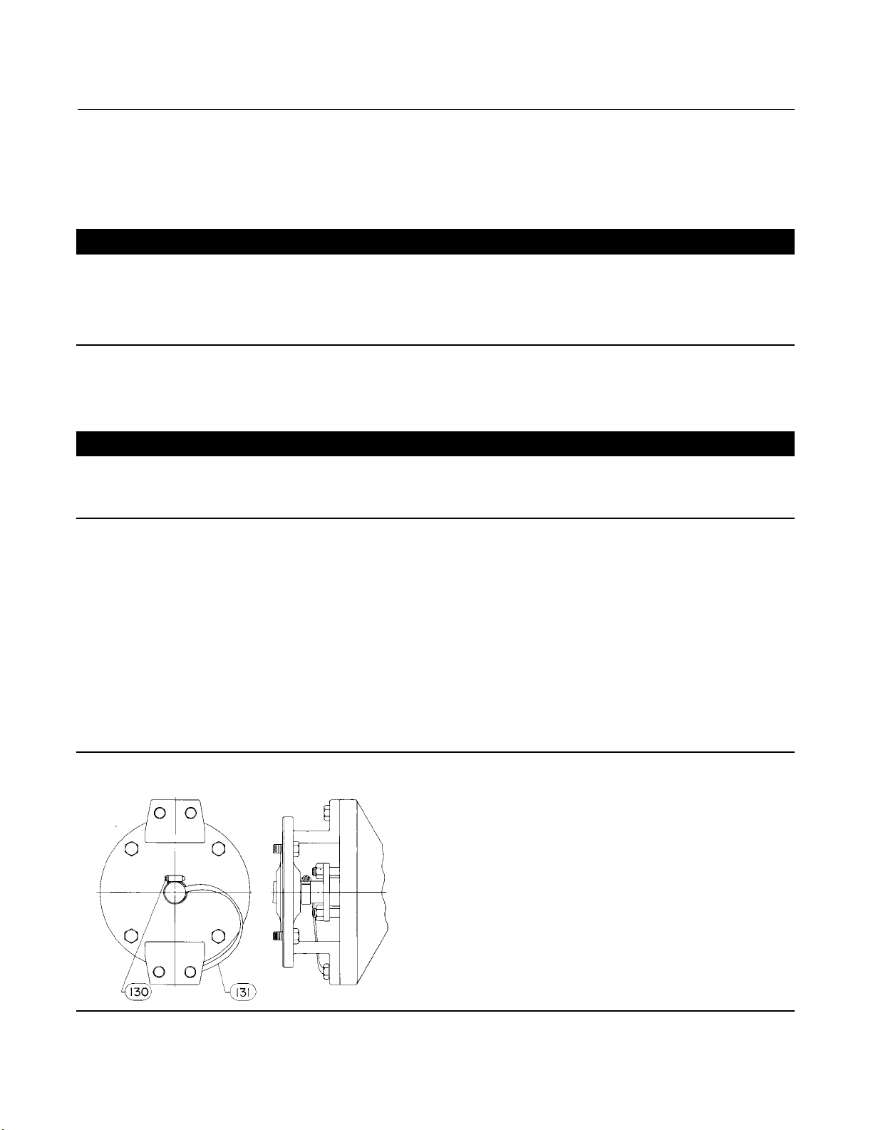
Figure 2. Optional Shaft-to-Valve Body Bonding Strap Assembly
5
Page 6
8510B Valve (EMA)
November 2011
Instruction Manual
D251400X012
WARNING
An 8510B valve body is not necessarily grounded when installed in a pipeline. If the valve is used in a flammable or
hazardous atmosphere or for oxygen service, an explosion could result due to a discharge of static electricity from the valve
components. To avoid personal injury or property damage, always make sure that the valve body is grounded to the
pipeline before putting the control valve assembly into operation in a flammable or hazardous atmosphere.
Note
Standard 8510B packings are composed of all conductive packing rings (graphite ribbon packing) or partially conductive packing
rings (such as a carbon-filled PTFE female adaptor with PTFE V-ring packing or a graphite composition packing ring with
PTFE/composition packing) to electrically bond the shaft to the valve body for hazardous area service. For oxygen service
applications, provide alternate shaft-to-valve body bonding according to the following step.
9. For oxygen service applications, attach the bonding strap assembly (key 131, figure 2) to the shaft with the clamp
(key 130, figure 2), and connect the other end of the bonding strap assembly to the valve body with the cap screw
(key 22). Secure each cap screw with a hex nut (key 30).
WARNING
Personal injury could result from packing leakage. Valve packing was tightened prior to shipment; however, the packing
might require some readjustment to meet specific service conditions.
Valves with ENVIRO-SEAL packing systems will not require this initial re-adjustment. See ENVIRO-SEAL Packing System
for Rotary Valves Instruction Manual (D101643X012) for packing instructions. If you wish to convert your present
packing arrangement to ENVIRO-SEAL packing, refer to the retrofit kits listed in the parts kit sub-section near the end
of this manual.
Maintenance
Valve body parts are subject to normal wear and must be inspected regularly and replaced as necessary. The frequency
of inspection and replacement depends upon the severity of service conditions. Instructions are given in this section
for: replacing packing; replacing disc, shaft, or bearing(s); changing disc rotation or valve action; and mounting and
adjusting the actuator.
As used in these instructions, actuator refers to power actuators (such as pneumatic diaphragm, piston actuators, and
rack and pinion actuators) or manual actuators (such as handwheel or handlever actuators).
WARNING
Avoid personal injury and property damage from sudden release of process pressure or bursting of parts. Before
performing any maintenance operations:
D Do not remove the actuator from the valve while the valve is still pressurized.
D Always wear protective gloves, clothing, and eyewear when performing any maintenance operations.
D Disconnect any operating lines providing air pressure, electric power, or a control signal to the actuator. Be sure the
actuator cannot suddenly open or close the valve.
6
Page 7

Instruction Manual
D251400X012
D Use bypass valves or completely shut off the process to isolate the valve from process pressure. Relieve process pressure
on both sides of the valve. Drain the process media from both sides of the valve.
D Vent the power actuator loading pressure and relieve any spring precompression.
D Uselock-outprocedurestobesurethattheabovemeasures s tay in effect while you work on the equipment.
D The valve packing box may contain process fluids that are pressurized, even when the valve has been removed from the
pipeline. Process fluids may spray out from under pressure when removing the packing hardware or packing rings, or
when loosening the packing box pipe plug.
D Check with your process or safety engineer for any additional measures that must be taken to protect against process
media.
8510B Valve (EMA)
November 2011
Packing Maintenance
Key numbers are referenced in figure 3 unless otherwise indicated. All maintenance operations in this section may be
performed with the valve in the line. Packing may be PTFE V-ring or graphite.
An ENVIRO-SEAL packing system is also available with the 8510B control valve. To install the ENVIRO-SEAL packing
system in an existing valve, follow the instructions in the instruction manual included with the packing system
(D101643X012). To remove packing parts in a valve with the ENVIRO-SEAL packing system, follow the procedures for
valves with the ENVIRO-SEAL packing system in this section. Install the replacement packing following the instructions
in the packing system instruction manual (D101643X012).
Stopping Leakage
For valves with PTFE or graphite packing:
CAUTION
Tighten the packing flange only enough to prevent shaft leakage. Excessive tightening will only accelerate wear of the
packing and could produce higher torques on the valve.
Leakage around the packing followers can be stopped by tightening the packing flange nuts (key 12, figure 8).
If the packing is relatively new and tight on the shaft, and if tightening the packing flange nuts does not stop leakage,
the shaft may be worn or nicked so that a seal cannot be made. If the leakage comes from the outside diameter of the
packing, the leakage may be caused by nicks or scratches around the packing box wall. Inspect the shaft and packing
box wall for nicks and scratches when performing the packing replacement procedures.
For valves with the ENVIRO-SEAL packing system:
Optimum performance of the ENVIRO-SEAL packing system is obtained when the Belleville springs are tightened to
their “target load.” The target load is the point where the springs are compressed to 85% of their maximum deflection,
or nearly flat. Maximum deflection is when the springs are 100% compressed, or completely flat.
Under normal conditions, the packing nuts should not require re-tightening. However, when servicing, if the springs
do not remain at the target load of 85% compression, retighten the packing box nuts according to the following
procedure:
1. Tighten the packing flange nuts alternately and evenly, keeping the packing flange parallel with the valve flange
(see figure 3), until the Belleville springs are compressed 100% (or completely flat).
7
Page 8

8510B Valve (EMA)
November 2011
Instruction Manual
D251400X012
D For PTFE packing, loosen each packing flange nut one half turn (180_ of rotation).
D For Graphite packing, loosen each packing flange nut one quarter turn (90_ of rotation).
The target load of 85% compression has now been reached. If leakage continues, replace the packing components as
described in the following procedures.
Replacing the Packing
For valves with PTFE or graphite packing:
This procedure may be performed without removing the actuator from the valve body if adding split
PTFE/composition packing rings as a temporary measure on the actuator side of the valve body. However, the actuator
must be removed from the valve body if replacing any other kind of packing on the actuator side of the valve body.
Key numbers in this procedure are shown in figure 8 unless otherwise indicated.
1. Isolate the control valve from the line pressure, release pressure from both sides of the valve body, and drain the
process media from both sides of the valve. If using a power actuator, also shutoff all pressure lines to the power
actuator, release all pressure from the actuator. Use lock-out procedures to be sure that the above measures stay in
effect while you work on the equipment.
2. Remove the packing flange nuts (key 12) and packing follower (key 15), plus the packing flange (key 9) if used, from
thesideofthevalvebodyoppositetheactuator.
CAUTION
If removing the actuator in the following step, use a wheel puller to separate the actuator parts from the valve shaft. Do not
drive the actuator parts off the valve shaft because this could move the valve bearings and disc away from the centered
position, thereby damaging the disc and the valve body.
3. If necessary to remove the actuator, remove the cap screws and nuts (keys 22 and 30). Remove the clamp (key 130,
figure 2) if the strap (key 131, figure 2) is used. If necessary, refer to separate actuator instruction manuals for
assistance in removing the actuator.
4. Remove the packing flange nuts and pull out the packing follower (key 16), plus the packing flange (key 10) if used,
fromtheactuatorsideofthevalvebody.
5. Remove the old packing rings (key 13) and, if used, the packing washers (key 27). Carefully avoid scratching the
shaft or packing box wall to avoid damage that could cause leakage around the shaft. Clean all accessible metal
parts and surfaces to remove particles that would prevent the packing from sealing.
8
Page 9

Instruction Manual
D251400X012
Figure 3. Packing Arrangement Details
8510B Valve (EMA)
November 2011
PTFE V-RING
SINGLE PTFE PACKING FOR
ACTUATOR END
PTFE COMPOSITION
STANDARD PACKING
GRAPHITE RIBBON
SINGLE PTFE PACKING FOR
OUTBOARD END
GRAPHITE PACKING FOR
ACTUATOR END
GRAPHITE PACKING FOR
OUTBOARD END
ENVIRO-SEAL PACKING
NOTES:
1
WITH CONDUCTIVE PACKING, THE FEMALE ADAPTORIN PTFE V-RING PACKING IS CARBON-FILLED PTFE AND THE TOP RING IN COMPOSITION PACKING IS GRAPHITE/N06600.
2
APPLY LUBRICANT.
THESE TWO SURFACES SHOULD REMAIN PARALLEL AS YOU ALTERNATELYAND EVENLY TIGHTEN THE PACKING NUTS (KEY 101).
3
9
Page 10

8510B Valve (EMA)
November 2011
Note
Except with oxygen service, lightly lubricate new PTFE V-rings with phenylmethyl silicone lubricant to aid in assembly.
Instruction Manual
D251400X012
WARNING
Do not lubricate parts when used in oxygen service, or where the lubrication is incompatible with the process media. Any
use of lubricant can lead to the sudden explosion of media due to the oil/oxygen mixture, causing personal injury or
property damage.
6. Use the appropriate procedures below for installing packing in either end of the valve.
D Install the packing washers (key 14), and packing rings (key 13). Make sure that PTFE/composition packing rings are
installed so that the ring splits do not line up to form a leak path.
D With graphite ribbon packing, stack the packing rings and packing washers together as shown in figure 3, and slide
the stack into the packing box as far as it will go while carefully avoiding trapping air among the rings.
D Install both packing followers and, if used, the packing flanges.
D Install the packing flange nuts, and tighten them only far enough to stop leakage under normal operating
conditions. For oxygen service applications, perform the next step.
D For oxygen service applications, attach the bonding strap assembly (key 131, figure 2) to the shaft with the clamp
(key 130, figure 2), and connect the other end of the bonding strap assembly to the valve body with a cap screw
(key 22). Secure each cap screw with a hex nut (key 30).
7. Mount the actuator, if it was removed from the valve body, and adjust the actuator travel before returning the valve
to service. This is necessary due to the measurements that must be made during the actuator adjustment process.
Refer to the Actuator Mounting section of this manual or to the separate actuator instruction manual for mounting
and adjusting instructions before proceeding.
8. When placing the control valve into operation, check around the packing follower or leakage; retighten the packing
flange nuts as required according to accepted bolting procedures.
For valves with ENVIRO-SEAL packing systems:
To replace the packing at the actuator side of the valve, the actuator must be removed. Also, the valve should be
removed from the pipeline to allow proper readjustment of the disc position.
CAUTION
If removing the actuator, use a wheel puller to separate the actuator parts from the valve shaft. Do not drive the actuator
parts off the valve shaft because this could move the valve bearings and disc away from the centered position, thereby
damaging the disc and the valve body.
1. Isolate the control valve, and shut off all pressure lines to the power actuator. Release pressure from the valve body
and actuator, and disconnect the pressure lines from the actuator if it will be removed from the valve body.
10
Page 11

Instruction Manual
D251400X012
2. Loosen the two packing hex nuts evenly to remove spring tension, then remove the nuts.
3. Remove the packing flange and spring pack assembly. The spring pack assembly consists of the spring stack and
packing follower. The spring stack is retained on the packing follower by an O-ring. Remove the anti-extrusion
washer, the packing set, and the packing ring.
8510B Valve (EMA)
November 2011
CAUTION
The valve shaft surface condition is critical in making and maintaining a good seal. If the valve shaft surface is scratched,
nicked, dented, or worn, replace the valve shaft before replacing the packing system.
4. Inspect the existing valve shaft. If necessary, replace the valve shaft as described in the procedures in this section.
5. Install the new packing system components as described in the ENVIRO-SEAL Packing System for Rotary Valves
Instruction Manual (D101643X012).
6. Mount the actuator, if it was removed from the valve body, and adjust the actuator travel before returning the valve
to service. This is necessary due to the measurements that must be made during the actuator adjustment process.
Refer to the Actuator Mounting section of this manual or to the separate actuator instruction manual for mounting
and adjusting instructions.
Replacing the Seal Ring
Perform this procedure only if the control valve is not shutting off properly (that is, leaking downstream). This
procedure does not require removing the actuator from the valve body.
Key numbers in this procedure are shown in figure 8 unless otherwise indicated.
1. Isolate the control valve from line pressure, and relieve pressure from the valve body. Shut off and disconnect all
lines from the power actuator.
WARNING
The edges of a rotating disc have a shearing effect that may result in personal injury. To help prevent such injury, stay clear
of the disc edges when rotating the disc (key 3).
CAUTION
Damage to the disc (key 3) may occur if the disc is not closed when the valve is being removed from the pipeline. If
necessary, apply operating pressure to the actuator temporarily to retain the disc in the closed position while removing the
valve from the pipeline.
2. Unscrew the flange bolts, and remove the valve from the pipeline.
3. Unscrew the machine screws (key 8), and remove the seal retainer (key 2) and the retainer clip (key 34).
4. Remove the seal ring or seal ring assembly (key 4). The spring (key 5) is removed with a PTFE seal ring.
5. For metal seal ring assemblies, replace the gaskets (key 4C) if the entire seal ring assembly is not replaced. Scrape
off the old gaskets from both sides of the seal ring and the seal ring sides of the valve body (key 1) and seal retainer.
Clean the gasket surfaces.
11
Page 12

8510B Valve (EMA)
November 2011
6. Reconnect or mount the actuator (if it was removed) before proceeding.
For an actuator with adjustable travel, also adjust the actuator before proceeding. This is necessary due to the
measurements that must be made during the actuator adjustment process.
Refer to the Actuator Mounting section of this manual and to the separate actuator instruction manual for mounting
and adjusting instructions.
7. The valve should be closed during seal ring installation to permit accurate centering of the seal. To install the new
seal ring:
D For a PTFE seal, if the spring (key 5) was disassembled, hook the spring ends together. Work the spring into the
recess in the seal ring (key 4). Install the seal ring and spring assembly into the recess in the valve body as shown in
figure 8.
D For the metal seal ring assembly, install the seal ring assembly (key 4) as shown in figure 8.
Instruction Manual
D251400X012
CAUTION
New seal ring gaskets (key 4C) are very fragile and must be handled very carefully to avoid gasket kinking, cracking, or
breakage that can cause leakage between the seal ring, seal retainer, and valve body. To avoid gasket damage, make sure
that the valve body is lying flat so that the gaskets do not shift before the following step and step 8 are completed.
D For a metal seal ring on which the gaskets will be replaced, lay the following parts down in order so that they are
accurately centered on the valve body: one new gasket; thesealringorientedasshowninfigure8,andthesecond
new gasket.
8. Attach the seal retainer (key 2) and the retainer clips (key 34) to the valve body and secure with the machine screws
(key 8). Tighten the machine screws evenly so as not to crack or break the metal seal gaskets.
9. Be certain the disc is closed before installing the valve according to the Installation section of this instruction
manual.
Replacing the Disc and Shaft Assembly or the Bearings
Perform this procedure to replace the valve disc, shaft, and taper key assembly if the disc does not rotate in response
to rotation of the actuator end of the valve shaft. Key numbers in this procedure are shown in figure 8 unless otherwise
indicated.
Disassembly
1. Remove the seal ring according to steps 1 through 5 of the Replacing Seal Ring section.
CAUTION
Use a wheel puller to separate actuator parts from the valve shaft. Driving the parts off the valve shaft could move the valve
bearings and disc away from the centered position, damaging the disc and valve body.
2. Remove the cap screws (key 22) and hex nuts (key 30). Remove the clamp (key 130, figure 2) if the strap (key 131,
figure 2) is used. Remove the actuator from the valve body (key 1) while referring to the separate actuator
instruction manual for assistance.
12
Page 13

Instruction Manual
D251400X012
8510B Valve (EMA)
November 2011
3. Rotate the disc (key 3) to the fully open position.
4. Refer to figure 8 and determine the location of the smaller end of the taper key (key 21). Drive out the taper key
towards the larger end.
5. Unscrew and remove the packing flange nuts (key 12), packing followers (keys 15 and 16), and packing flanges
(keys 9 and 10) if used, from both sides of the valve body.
WARNING
Once the shaft has been removed in the following step, the disc may fall from the valve body. To avoid personal injury and
disc damage, support the disc to prevent it from falling as the shaft is being removed.
6. Pulltheshaftoutthroughtheactuatorsideofthevalvebody.Iftheshaftcannotbepulledfree,carefullyuseapin
punch to drive the shaft out from the side opposite the actuator. Do not damage the end of the shaft with the
punch.
7. Remove the disc and spacers (key 7) from the valve body.
8. Remove the packing rings (key 13, figure 3), the packing washers (key 27, figure 3) if used, and the packing box
rings (key 14, figure 3) from both sides of the valve body.
9. If either of the bearings (key 6) require maintenance or replacement, press them out, or remove them using a
bearing puller. (See figure 4 for the puller dimensions.) For constructions with a metal bearing, also remove the
bearing stop (key 25) with the bearing.
10. Clean the packing boxes andmetalpackingboxparts.
Assembly
Note
Before performing the following step, lubricate the outer bearing surfaces--except on oxygen service--with dry-film lubricant to
facilitate future removal. Do not lubricate the insides of PTFE-lined bearings.
WARNING
Do not lubricate bearings that will be used for oxygen service, or where the lubrication is incompatible with the process
media. Any
injury or property damage.
1. If new bearings and, if used, bearing stops (key 25) are required, insert them through the packing boxes. Press the
bearings in until the bearing end is flush with the valve body bore at one point and the remainder of the bearing end
protrudes into the valve body bore. Or, use a bearing puller (see figure 4 for puller dimensions) to properly install
and locate the new bearings and the bearing stops.
2. Install spacers (key 7) into the disc (key 3). The spacers fit loosely in the disc.
Note
If contaminating the process fluid with grease is a concern, do not apply grease according to the following step; especially if the
thorough cleaning in step 7 cannot be performed.
use of lubricant can lead to the sudden explosion of media due to the oil/oxygen mixture, causing personal
13
Page 14

8510B Valve (EMA)
November 2011
Figure 4. Bearing Puller Dimensions
Instruction Manual
D251400X012
REFERTOTABLES4,5,AND6
mm
47A8111-C
A2882-3
Table 4. Puller Dimensions for Bearing Stop
VALVE
SIZE, NPS
2
3
4
6
8&10
12 41.76 1.644 38.96 1.534 35.71 1.406 41.28 1.625 60.33 2.375
1. Tolerance for the A&B dimensions are indicated by showing maximum and minimum dimensions.
A B C D E
mm Inch mm Inch mm Inch mm Inch mm Inch
15.49 0.610 13.56 0.534
15.37 0.605 13.44 0.529
18.67 0.735 16.74 0.659
18.54 0.730 16.61 0.654
22.71 0.894 19.91 0.784
22.58 0.889 19.79 0.779
29.06 1.144 26.26 1.034
28.93 1.139 26.14 1.029
35.41 1.394 32.61 1.284
35.28 1.389 32.49 1.279
(INCH)
(1)
10.31 0.406 14.29 0.563 33.34 1.313
13.49 0.531 15.88 0.625 34.93 1.375
16.66 0.656 22.23 0.875 41.28 1.625
23.01 0.906 28.58 1.125 47.63 1.875
29.36 1.156 34.93 1.375 53.98 2.125
14
Page 15
Instruction Manual
D251400X012
8510B Valve (EMA)
November 2011
Table 5. Puller Dimensions for PTFE Bearings
VALVE
SIZE, NPS
2
3
4
6
8&10
12 41.76 1.644 38.05 1.498 34.93 1.375 85.73 3.375 104.8 4.125
1. Tolerance for the A&B dimensions are indicated by showing maximum and minimum dimensions.
A B C D E
mm Inch mm Inch mm Inch mm Inch mm Inch
15.49 0.610 12.65 0.498
15.37 0.605 12.52 0.493
18.67 0.735 15.82 0.623
18.54 0.730 15.70 0.618
22.71 0.894 19.00 0.748
22.58 0.889 18.87 0.743
29.06 1.144 25.35 0.998
28.93 1.139 25.22 0.993
35.41 1.394 31.70 1.248
35.28 1.389 31.57 1.243
Table 6. Puller Dimensions for Metal Bearings
VALVE
SIZE, NPS
2
3
4
6
8&10
12 41.76 1.644 38.10 1.500 34.93 1.375 41.28 1.625 60.33 2.375
1. Tolerance for the A&B dimensions are indicated by showing maximum and minimum dimensions.
A B C D E
mm Inch mm Inch mm Inch mm Inch mm Inch
15.49 0.610 12.70 0.500
15.37 0.605 12.57 0.495
18.67 0.735 15.88 0.625
18.54 0.730 15.72 0.619
22.71 0.894 19.05 0.750
22.58 0.889 18.92 0.745
29.06 1.144 25.40 1.000
28.93 1.139 25.27 .995
35.41 1.394 31.75 1.250
35.28 1.389 31.62 1.245
(1)
9.53 0.375 33.24 1.313 50.80 2.000
12.70 0.500 39.70 1.563 58.74 2.313
15.88 0.625 47.63 1.875 66.68 2.625
22.23 0.875 60.33 2.375 79.38 3.125
28.58 1.125 73.03 2.875 92.08 3.625
(1)
9.53 0.375 15.88 0.625 34.93 1.375
12.70 0.500 20.64 0.813 39.69 1.563
15.88 0.625 22.23 0.875 41.28 1.625
22.23 0.875 28.58 1.125 47.63 1.875
28.58 1.125 34.93 1.375 53.98 2.125
3. Apply a small amount of heavy grease to the spacers. The grease will help to hold the spacers in place during the
subsequent centering procedure.
D Valves with PTFE bearings use one PTFE coated spacer on each side of the disc. Install the spacer with the PTFE side
against the disc.
D Valves with metal bearings use two metal spacers on each side of the disc.
4. Insert the disc into the valve body. Be certain the taper key hole in the disc is on the actuator side of the valve body.
5. Slide the shaft through the valve body and disc.
6. Rotate the disc to the closed position. Measuring carefully, center the disc in the valve body bore. With the disc
centered, use a feeler gauge to measure the clearance between each spacer and bearing. The clearance between
each spacer and bearing should be equal and should be as close as possible to the value given in figure 5. If
necessary, remove the disc and shaft, and reposition the bearings. Reinstall the disc and shaft, and repeat the
centering and measuring process.
7. If the grease used to hold the spacers will contaminate the process fluid, disassemble the shaft and disc, remove the
spacers, and clean the shaft, disc, valve body bore, and spacers thoroughly. Reinstall the disc and spacers into the
valve body. Insert the shaft into the valve body and through the disc.
15
Page 16

8510B Valve (EMA)
November 2011
Figure 5. Spacer-Bearing Clearance (Metal Bearing Assembly Shown)
MEASURE
CLEARANCE
HERE
41B6065-A
SPACER TO BEARING CLEARANCE
VALVE BODY SIZE, NPS
2,3, & 4
6
8
10
12
mm Inches mm Inches
0.102
0.152
0.203
0.254
0.305
Minimum Maximum
0.004
0.006
0.008
0.010
0.012
0.229
0.279
0.330
0.381
0.432
Instruction Manual
D251400X012
0.009
0.011
0.013
0.015
0.017
Table 7. Recommended Bolt Torques for Actuator-Mounting Cap Screws
VALVE SIZE, NPS
2, 3, 4, and 6 87.7 60
8, 10, and 12 135 100
RECOMMENDED TORQUE RECOMMENDED TORQUE
NSm lbfSin.
8. Slide the shaft all the way into the valve body.
9. Temporarily install the packing follower (key 16) or, if used, the packing flange (key 9). With the disc fully open,
rotate the shaft until the hole in the disc (key 3) aligns with the slot in the shaft. Insert the taper key (key 21), small
end first, into the taper key hole. Do not drive in the taper key. Remove the packing follower or flange.
D Current standard construction materials require the taper key (key 21) to be tack welded in place after properly
seating.
Note
Make sure the drive shaft (key 20) is free of oil or grease, otherwise the taper key will not seat properly.
Failure to properly set the taper key could result in it coming loose while in service.
10. Insert a packing box ring (key 14) into each packing box.
11. Install the packing according to the appropriate instructions presented in steps 5 through 8 of the Replacing
Packing section.
16
Page 17

Instruction Manual
D251400X012
8510B Valve (EMA)
November 2011
12. Drive in the taper key until solid contact is felt, then:
a. Drive the taper key in farther as follows:
VALVE BODY SIZE, NPS MINIMUM ALLOWABLE DEPTH TO DRIVE TAPER KEY AFTER INITIAL SOLID CONTACT, mm (INCH)
2
3,4,6
8, 10, 12
3.2 (0.125)
4.8 (0.188)
5.7 (0.219)
b. The disc, shaft and taper key assembly must be inspected to verify that the taper key spans the entire shaft flat
width. If not, the taper key must be driven in farther until this condition i s satisfied. However, the following depth
limits must not be exceeded:
VALVE BODY SIZE, NPS MAXIMUM ALLOWABLE DEPTH TO DRIVE TAPER KEY AFTER INITIAL SOLID CONTACT, mm (INCH)
2
3&4
6
8&10
12
5.6 (0.219)
7.1 (0.281)
7.9 (0.312)
9.5 (0.375)
10.3 (0.406)
13. When the above conditions are met, tack weld the taper key (key 21) to the valve disc (key 3). Use a :
D 1/8inchdiameterweldonNPS2through6valves,
D 3/16 inch diameter weld on NPS 8 through 10 valves, and
D 1/4inchdiameterweldonNPS12valves.
14. Rotate the disc to the closed position.
15. Refer to the Replacing Seal Ring and Packing Maintenance procedures in this section.
Actuator Mounting
With the valve body out of the line, mount the actuator on the valve body in accordance with the instructions in the
actuator instruction manual. Mount the actuator yoke to the valve body, and tighten the actuator-mounting cap
screws and nuts (keys 22 and 30) to the appropriate torque from table 7. The valve body might have an optional disc
stop. Do not use the disc stop as a travel stop; use the actuator travel stop (if necessary, refer to the actuator
instruction manual).
Key numbers in this procedure are shown in figure 8 unless otherwise indicated.
1. If using a power actuator, determine the actuator mounting style and position from figure 6.
If using a manual handwheel or handlever actuator, refer to the appropriate actuator instruction manual for mounting
positions.
CAUTION
Rotating the disc (key 3) in the wrong direction will damage the seal ring (key 4). To avoid such damage, remove the seal
ring according to the following step before mounting the actuator.
2. Mark the orientation of the seal ring with respect to the valve body so that the seal can be reinstalled in its original
position. Remove the seal ring according to the procedure in the Replacing Seal Ring section of this instruction
manual.
17
Page 18

8510B Valve (EMA)
November 2011
Figure 6. Lever/Shaft/Disc Orientation with Valve Closed
TYPICAL ACTUATOR (1052) SECTIONAL THROUGH HOUSING
A3344
ACTUATOR
MOUNTING STYLE
VALVE CLOSED
4
MOUNTING
POSITION 1
5
ACTUATOR ROD
ACTUATOR ROD END BEARING
ACTUATOR LEVEL
LEVER INDEX MARKS (4)
VALVE SHAFT INDEX MARK
MOUNTING
POSITION 2
5
MOUNTING
POSITION 3
Instruction Manual
D251400X012
MOUNTING
5
POSITION 4
5
STYLE A
(PDTO)
RIGHTHAND
1
STYLE B
(PDTC)
3
STYLE C
(PDTC)
3
LEFTHAND
2
STYLE D
(PDTO)
NOTES:
1
WHENONEISFACINGTHEINLET,THEACTUATORISTOTHERIGHTOFTHEVALVEBODY.
2
WHEN ONE IS FACING THE INLET, THEACTUATOR IS TO THE LEFT OF THE VALVE BODY.
3
FOR 60-DEGREEOPERATION WITH PUSH-DOWN-TO-CLOSEACTION(EXTENDING ACTUATORRODCLOSES VALVE), ROTATEACTUATOR LEVER COUNTERCLOCKWISESO THAT
LEVER INDEX MARK IS OFFSET 1 SPLINETOOTHFROM VALVE SHAFT INDEX MARK FOR NPS 2 THROUGH 4 VALVES AND2 SPLINE TEETH FROM VALVE SHAFT INDEX MARK FOR
NPS 6 THROUGH 12 VALVES.
4
CURVED ARROWS IN ”VALVE CLOSED' COLUMN INDICATE ROTATION REQUIRED TO OPEN VALVE (COUNTERCLOCKWISE WHEN VIEWED FROMACTUATOR SIDE OF VALVE).
5
ARROWS IN ”MOUNTING POSITION'' COLUMNSINDICATE DIRECTION OF ACTUATOR ROD TRAVEL REQUIRED TO OPEN VALVE.
6. PDTC–PUSH DOWN TO CLOSE;PDTO–PUSHDOWN TO OPEN.
43A5323-B
B1125-1
FORWARD
FLOW
FORWARD
FLOW
FORWARD
FLOW
FORWARD
FLOW
18
Page 19

Instruction Manual
D251400X012
8510B Valve (EMA)
November 2011
CAUTION
To prevent damage to the valve seal, due to the disc rotating past the fully closed position, use the following procedures:
D For actuators with an adjustable turnbuckle, such as the Fisher 1051, 1052, or 1061 actuator, the turnbuc kle must be
adjusted so that the valve is closed (determined by measuring as shown in figure 7) when the diaphragm plate or piston
is against the actuator travel stop.
D For manually-operated actuators or actuators without adj ustable linkage, such as a Fisher 1066 or 1066SR actuator,
make certain the actuator travel stop prevents the disc from rotating past the fully closed position.
3. For actuators with an adjustable turnbuckle, adjust the turnbuckle to its minimum length to prevent damage. If
necessary, refer to the appropriate actuator instruction manual for assistance with adjustment.
4. For power actuators, refer to figure 6 to locate the view of the mounting style and position to be used. When
adjusting the actuator, be certain that the disc is rotated in the proper direction (clockwise to close when viewed
from the actuator side of the valve) and that the disc is not rotated beyond the limits defined in the Installation
section of this instruction manual.
5. For actuators with turnbuckles, adjust the turnbuckle to bring the disc to the fully closed position at the end of the
actuator stroke. Refer to the appropriate actuator instruction manual for assistance.
6. To determine the fully closed disc position (zero degrees of disc rotation), measure the distances between the disc
face and the retaining ring face (or from a line from the top to the bottom of the valve body) at the top and bottom
of the valve as shown in figure 7. When necessary, adjust the actuator to rotate the disc slightly until the two
measurements are equal.
7. Reinstall the seal ring according to the procedure in the Replacing Seal Ring section.
Figure 7. Sectional of Typical Valve Body
DISC STOP
STANDARD
FLOW
DIRECTION
NOTE:
1
THESE TWO MEASUREMENTS MUST BE EQUALTO ENSURE THAT THE DISC IS FULLY CLOSED
OPEN
Parts Ordering
When corresponding with your Emerson Process Management sales office about this equipment, always mention the
valve serial number. When ordering replacement parts, also specify the complete 11-character part number of each
part required from the following parts list.
19
Page 20

8510B Valve (EMA)
November 2011
Instruction Manual
D251400X012
WARNING
Use only genuine Fisher replacement parts. Components that are not supplied by Emerson Process Management should
not, under any circumstances, be used in any Fisher valve, because they may void your warranty, might adversely affect the
performance of the valve, and could cause personal injury and property damage.
Parts Kits
Retrofit Kits for ENVIRO-SEAL Packing
Retrofit kits are available for replacing the packing in an existing valve with an ENVIRO-SEAL packing system. These kits
are available for single PTFE or graphite packing. All parts required for installation of the ENVIRO-SEAL packing system
into an existing 8510B control valve are included in the kits. Select two kits, one for the actuator end of the valve and
one for the outboard end.
Worn shafts, packing box damage, or other components that do not meet Emerson Process Management finish
specifications, dimensional tolerances, and design specifications, may adversely alter the performance of the retrofit
kit.
ENVIRO-SEAL Packing System Retrofit Kits for Splined Shafts
SHAFT DIAMETER SINGLE PTFE PACKING GRAPHITE PACKING
mm Inches ForActuatorEndPackingBox For Outboard End Packing Box ForActuatorEndPackingBox For Outboard End Packing Box
12.7
15.9
19.1
25.4
31.8
38.1
1/2
5/8
3/4
1
1-1/4
1-1/2
RRTYXRT0012
RRTYXRT0022
RRTYXRT0032
RRTYXRT0052
RRTYXRT0062
RRTYXRT0072
RRTYXRT0082
RRTYXRT0092
RRTYXRT0102
RRTYXRT0112
RRTYXRT0122
RRTYXRT0132
RRTYXRT0312
RRTYXRT0322
RRTYXRT0332
RRTYXRT0352
RRTYXRT0362
RRTYXRT0372
RRTYXRT0382
RRTYXRT0392
RRTYXRT0402
RRTYXRT0412
RRTYXRT0422
RRTYXRT0432
ENVIRO-SEAL Packing System Retrofit Kits for Double D End Connection with Anti-Blowout Shaft
SHAFT DIAMETER SINGLE PTFE PACKING GRAPHITE PACKING
mm Inches ForActuatorEndPackingBox For Outboard End Packing Box ForActuatorEndPackingBox For Outboard End Packing Box
12.7
15.9
19.1
25.4
31.8
38.1
1/2
5/8
3/4
1
1-1/4
1-1/2
RRTYXRT0972
RRTYXRT0982
RRTYXRT0992
RRTYXRT1012
RRTYXRT1022
RRTYXRT1032
RRTYXRT0082
RRTYXRT0092
RRTYXRT0102
RRTYXRT0112
RRTYXRT0122
RRTYXRT0132
RRTYXRT1072
RRTYXRT1082
RRTYXRT1092
RRTYXRT1102
RRTYXRT1112
RRTYXRT1122
RRTYXRT0382
RRTYXRT0392
RRTYXRT0402
RRTYXRT0412
RRTYXRT0422
RRTYXRT0432
Repair Kits for ENVIRO-SEAL Packing
Repair kits for ENVIRO-SEAL PTFE packing include one packing set and two anti-extrusion washers. Repair kits for
ENVIRO-SEAL graphite packing include two packing rings and two anti-extrusion rings. A quantity of two of the
appropriate kit is required to repair both ends of the valve.
Worn shafts, packing box damage, or other components that do not meet Emerson Process Management finish
specifications, dimensional tolerances, and design specifications, may adversely alter the performance of the repair
kit.
20
Page 21

Instruction Manual
D251400X012
ENVIRO-SEAL Packing System Repair Kits
SHAFT DIAMETER
mm Inches
12.7
15.9
19.1
25.4
31.8
38.1
1/2
5/8
3/4
1
1-1/4
1-1/2
FOR PTFE PACKING FOR GRAPHITE PACKING
Parts List
Note
Part numbers are shown for recommended spares only. For part
numbers not shown, contact your Emerson Process Management sales
office.
Except where indicated, sizes shown are v alve body sizes.
Key Description Part Number
1 Valve Body ---
Note
The valve body is available as an assembly only. If valve body
replacement information is necessary, contact your Emerson Process
Management sales office.
2* Seal Retainer See following table
Part numbers are listed for steel and stainless steel only. For alloy
construction part numbers, contact your Emerson Process
Management sales office.
3ValveDisc
4* Seal Ring
4* Seal Ring Assembly, All-metal seal
4C* Gasket, graphite laminate (2 req'd)
5* Spring (PTFE seal ring only)
6* Bearing (2 req'd)
*Recommended spare parts
1. To make certain that a springisavailablewith each seal ring, a new spring (key 5) should
be ordered to be stocked with each ring ordered.
(1)
, PTFE See following table
S31600 (316 SST) & graphite laminate (Assembly
includes gaskets. For gasket only, see key 4C below)
NPS 2 17A7544X022
NPS 3 17A7550X022
NPS 4 17A7556X022
NPS 6 17A8171X022
NPS 8 17A8172X022
NPS 10 18A1129X022
NPS 12 18A1139X022
NPS 8 17A7567X012
NPS 10 18A1128X012
PTFE/composition lining with S31603 (316L SST) jacket
(Reinforced PTFE in phenolic resin. Emerson Process Management
designation is FMS 30B4.)
NPS 2 12A9015X272
NPS 3 12A8904X292
NPS 4 12A8985X332
NPS 6 12A8819X362
(1)
See following table
RRTYX000012
RRTYX000022
RRTYX000032
RRTYX000052
RRTYX000062
RRTYX000072
8510B Valve (EMA)
November 2011
13B8816X012
13B8816X032
13B8816X052
13B8816X092
13B8816X112
13B8816X142
Key Description Part Number
NPS 8 & 10 12A8965X262
NPS 12 12A8928X242
Filled PTFE with S31603 (316L SST) jacket (PTFE with selected
fillers. Emerson Process Management designation is FMS 30B5.)
NPS 2 12A9015X282
NPS 3 12A8904X302
NPS 4 12A8985X322
NPS 6 12A8819X372
NPS 8 & 10 12A8965X272
NPS 12 12A8928X272
S44004 (440C SST)
NPS 2 14A6543X012
NPS 3 12A9300X012
NPS 4 14A5698X012
NPS 6 14A4618X012
NPS 8 & 10 14A5699X012
NPS 12 14A6549X012
Alloy 6B
NPS 2 14A6544X012
NPS 3 14A6545X012
NPS 4 14A6546X012
NPS 6 14A6547X012
NPS 8 & 10 14A6548X012
NPS 12 14A6550X012
Silver-plated alloy 6B
NPS 2 14A6536X012
NPS 3 12A9161X012
NPS 4 14A6537X012
NPS 6 14A2498X012
NPS 8 & 10 14A6538X012
NPS 12 14A6539X012
7* Spacer
For PTFE lined or filled PTFE bearings
PTFE/S31603 (316LSST) (2 req'd)
NPS 2 16A6036X092
NPS 3 16A6045X162
NPS 4 16A6041X152
NPS 6 16A6033X102
NPS 8 & 10 16A6055X062
NPS 12 16A6061X152
For S44004 (440C SST) bearings
S17700 (17-7 PH SST) (4 req'd)
NPS 2 18B9857X022
NPS 3 11B9444X012
NPS 4 11B9608X012
NPS 6 12B1356X012
NPS 8 & 10 12B1997X012
NPS 12 12B3905X012
For alloy 6B or silver-plated alloy 6B bearings
Alloy6B(4req'd)
NPS 2 18B9857X022
NPS 3 11B9444X022
NPS 4 11B9608X022
21
Page 22

8510B Valve (EMA)
November 2011
Key Description Part Number
Instruction Manual
D251400X012
NPS 6 12A1356X022
NPS 8 & 10 12B1997X022
NPS 12 12B3905X022
8 Cap Screw (SST)
NPS2through8(2req'd) NPS10&12(4req'd)
9 Packing Flange
10 Packing Flange
11 Packing Flange Stud (4 req'd)
12 Packing Flange Nut (4 req'd)
13* PackingSet (2 req'd)
PTFE & carbon-filled PTFE V-ring
(standard)
NPS 2 12A9016X022
NPS 3 1R5795X0012
NPS 4 12A8995X022
NPS 6 12A8832X022
NPS 8 & 10 12A8951X022
NPS 12 12A8935X022
PTFE V-ring (nonconductive)
NPS 2 12A9016X012
NPS 3 1R579501012
NPS 4 12A8995X012
NPS 6 12A8832X012
NPS 8 & 10 12A8951X012
NPS 12 12A8935X012
Packing Parts (included in packing set)
Female Adaptor (2 req'd)
Carbon-filled PTFE (standard)
NPS 2 1H7844X0012
NPS 3 1R5794X0012
NPS 4 12A8992X022
NPS 6 12A8831X022
NPS 8 & 10 12A8953X022
NPS 12 12A8932X022
PTFE (nonconductive)
NPS 2 1H784401012
NPS 3 1R579401012
NPS 4 12A8992X012
NPS 6 12A8831X012
PTFE (nonconductive)
NPS 8 & 10 12A8953X012
NPS 12 12A8932X012
Packing Ring, PTFE (6 req'd)
NPS 2 1H784301012
NPS 3 1R579301012
NPS 4 12A8994X012
NPS 6 12A8830X012
NPS 8 & 10 12A8954X012
NPS 12 12A8933X012
Male Adaptor, PTFE (2 req'd)
NPS 2 1H784201012
NPS 3 1R579201012
NPS 4 12A8993X012
NPS 6 12A8829X012
NPS 8 & 10 12A8952X012
NPS 12 12A8934X012
13* Packing Ring (8 req'd) (not req'd for V-ring packing set)
Graphite ribbon
NPS 2 12A9134X012
NPS 3 12A9135X012
NPS 4 12A9136X012
NPS 6 12A9137X012
NPS 8 & 10 12A9138X012
NPS 12 12A9139X012
Note
When ordering a PTFE-composition & graphite composition/N06600
packing ring arrangement, order 6 PTFE-composition packing rings and
2 graphite composition/N06600 packing rings per valve.
Key Description Part Number
PTFE-composition (6 req'd)
NPS 2 1P390501042
NPS 3 1J822501042
NPS 4 14A1937X012
NPS 6 14A0915X012
NPS 8 & 10 14A0916X012
NPS 12 14A1933X012
Graphite composition/N06600 (2 req'd)
NPS 2 1P3905X0172
NPS 3 1J8225X0182
NPS 4 14A1937X042
6-inch 14A0915X042
NPS 8 & 10 14A0916X072
NPS 12 14A1933X022
14* PackingBox Ring
S31600 (316L SST) (2 req'd)
NPS 2 16A6082X052
NPS 3 16A6083X092
NPS 4 16A6084X062
NPS 6 16A6085X062
NPS 8 & 10 16A6086X082
NPS 12 16A6087X072
15 Packing follower, CF8M (316 SST)
16 Packing follower, SST
18 DriveScrew, SST (2 req'd)
20 Valve Shaft
Splined Shaft Connection
S17400 (17-4 PH SST)
NPS 2 31B2526X012
NPS 3 31B6892X012
NPS 4 31B9456X012
NPS 6 32B1347X012
NPS 8 32B1994X012
NPS 10 32B2824X012
NPS 12 32B3901X012
S20190
Do not use with S44004 (440C SST) bearings
NPS 2 31B2526X022
NPS 3 31B6892X022
NPS 4 31B9456X022
NPS 6 32B1347X022
NPS 8 32B1994X022
NPS 10 32B2824X022
NPS 12 32B3887X022
Double D End Connection and Anti-Blowout Shaft
S17400 (17-4 PH SST)
NPS 2 3Q57352F012
NPS 3 3Q57353F012
NPS 4 3Q57354F012
NPS 6 3Q57355F012
NPS 8 3Q57356F012
NPS 10 3Q57357F012
NPS 12 3Q57358F012
22
*Recommended spare parts
Page 23

Instruction Manual
D251400X012
Figure 8. Typical Fisher 8510B Valve Assemblies
INBOARD CONSTRUCTION DETAIL
CONSTRUCTION DETAIL
8510B Valve (EMA)
November 2011
FOR METAL BEARING ASSEMBLY
OUTBOARD ALLOY
41B6065-A
SEE VIEW A IN
FIGURE 9
WITH SPLINED SHAFT CONNECTION
INBOARD ALLOY
CONSTRUCTION DETAIL
41B6065
WITH DOUBLE D CONNECTION AND BLOWOUT SHAFT
23
Page 24

8510B Valve (EMA)
November 2011
Figure 9. Seal Details
METALSEALASSEMBLY
SEAL RETAINER
SCREW
RETAINER CLIP
SPRING
Instruction Manual
SEE VIEW B
NOTE:
KEY NUMBERS 4A AND 4B ARENOT SHOWN
SEAL RETAINER
D251400X012
PTFE SEAL RING
41b6065-A
A5540-1
VIEW A DETAIL OF PTFE SEAL
Key Description Part Number
20 Valve Shaft (continued)
Double D End Connection and Anti-Blowout Shaft
S20190
Do not use with S44004 (440C SST) bearings
NPS 2 3Q57352F022
NPS 3 3Q57353F022
NPS 4 3Q57354F022
NPS 6 3Q57355F022
NPS 8 3Q57356F022
NPS 10 3Q57357F022
21* Taper Key, S20910
22 Cap Screw (2 req'd for 2 & 3-inch;
23 Nameplate, stainless steel 11B9434X0A2
25* Bearing Stop (2 req'd) S31600 (316 SST)
NPS 12 3Q57358F022
NPS 2 11B0654X012
NPS 3 11B0674X012
NPS 4 11B0674X012
NPS 6 11B0695X012
NPS 8 & 10 11B0722X012
NPS 12 11B4684X012
4 req'd on all other sizes)
For use with metal bearings (not shown)
NPS 2 14A6531X022
NPS 3 12A9162X012
NPS 4 14A5697X022
NPS 6 14A2497X012
NPS 8 & 10 14A5700X022
NPS 12 14A6532X022
GASKET
BACKUP RING
METALSEALRING
VIEW B DETAIL OF METAL SEAL
Key Description Part Number
26 Line Flange Stud (not shown)
27 Packing Washer, zinc (6 req'd)
29* LineFlange Gasket, FGM (2 req'd)
(use only when specified) (not shown)
Recommended for temperatures
above 650_F (343_C)
CL150
NPS 2 16A6224X012
NPS 3 16A6226X012
NPS 4 16A6228X012
NPS 6 & 8 16A6231X012
NPS 10 16A6237X012
NPS 12 16A6239X012
CL300
NPS 2 16A6225X012
NPS 3 16A6227X012
NPS 4 16A6229X012
NPS 6 & 8 16A6232X012
NPS 10 16A6238X012
NPS 12 16A6240X012
CL600
NPS 2 16A6225X012
NPS 3 16A6227X012
NPS 4 16A6230X012
NPS 6 & 8 16A6233X012
30 Hex Nut
32 Nameplate, stainless steel
33 Nameplate Wire
34 Retainer Clip, S31600
130 Clamp, stainless steel (req'd w/nonconductive packing)
131 Bonding Strap Assembly (req'd w/nonconductive packing)
24
*Recommended spare parts
Page 25

Instruction Manual
D251400X012
8510B Valve (EMA)
November 2011
ENVIRO-SEAL PACKING
Key Description Part Number
100 Packing Stud (4 required)
101 Packing Nut (4 required)
102 Packing Flange (2 required)
103 Spring Pack Assembly
104 Spring Pack Outboard
105* Packing Set
Single PTFE Packing
NPS 2 12B7053X012
NPS 3 12B7402X012
NPS 4 12B7414X012
NPS 6 12B7438X012
NPS 8 12B7450X012
NPS 10 12B7450X012
NPS 12 12B7643X012
Graphite Packing
NPS 2 13B8816X012
NPS 3 13B8816X032
NPS 3 13B8816X052
Key 2*, Seal Retainer, ASME
VALVE SIZE, NPS
2
3
4
6
8
10
12
FOR COMPOSITION SEAL FOR ALL-METAL SEAL
SA-514-70
Steel
21B4666X012
21B6894X012
21B9458X012
22B1343X012
22B1988X012
28A1124X012
28A1134X012
S31603
(316L SST)
21B4666X062
21B6894X062
21B9458X062
22B1343X032
22B1988X032
28A1124X132
28A1134X172
Key Description Part Number
NPS 6 13B8816X092
NPS 8 13B8816X112
NPS 10 13B8816X112
106* Anti-extrusion Ring
107* Packing Box Ring
111 Tag
112 Cable Tie
NPS 12 13B8816X142
Single PTFE Packing
NPS 2 12B7054X012
NPS 3 12B7406X012
NPS 4 12B7418X012
NPS 6 12B7442X012
NPS 8 12B7454X012
NPS 10 12B7454X012
NPS 12 12B7646X012
NPS 2 16A6082X012
NPS 3 16A6083X012
NPS 4 16A6084X012
NPS 6 16A6085X012
NPS 8 16A6086X012
NPS 10 16A6086X012
NPS 12 16A6086X012
SA-515-70
Steel
21B4667X012
21B6895X012
21B9459X012
22B1344X012
22B1989X012
28A1125X012
28A1135X012
S31603
(316L SST)
21B4667X032
21B6895X032
21B9459X032
22B1344X032
22B1989X032
28A1125X132
28A1135X092
*Recommended spare parts
25
Page 26

8510B Valve (EMA)
November 2011
Key 2* Seal Retainer, DIN
VALVE
SIZE,
NPS
2
3
4
6
8
2
3
4
6
8
10
8
10
12
12
12
12
12
SEAL MATERIAL
PTFE Composition 21B4668X092 21B4668X152 21B4668X162 21B4668X142
All-Metal Seal 21B4669X062 21B4669X092 21B4669X102 21B4669X082
PTFE Composition 21B6896X092 21B6896X152 21B6896X162 21B6896X142
All-Metal Seal 21B6897X062 21B6897X092 21B6897X102 21B6897X082
PTFE Composition 21B9458X212 21B9458X272 21B9458X282 21B9458X262
All-Metal Seal 21B9459X112 21B9459X142 21B9459X152 21B9459X132
PTFE Composition 22B1345X092 22B1345X152 22B1345X162 22B1345X142
All-Metal Seal 22B1346X062 22B1346X092 22B1346X102 22B1346X082
PTFE Composition 22B1992X092 22B1992X152 22B1992X162 22B1992X142
All-Metal Seal 22B1993X062 22B1993X092 22B1993X102 22B1993X082
PTFE Composition 21B4668X012 21B4668X072 21B4668X082 21B4668X062
All-Metal Seal 21B4669X012 21B4669X042 21B4669X052 21B4669X032
PTFE Composition 21B6896X012 21B6896X072 21B6896X082 21B6896X062
All-Metal Seal 21B6897X012 21B6897X042 21B6897X052 21B6897X032
PTFE Composition 21B9458X012 21B9458X192 21B9458X202 21B9458X062
All-Metal Seal 21B9459X012 21B9459X092 21B9459X102 21B9459X032
PTFE Composition 22B1345X012 22B1345X072 22B1345X082 22B1345X062
All-Metal Seal 22B1346X012 22B1346X042 22B1346X052 22B1346X032
PTFE Composition 22B1990X012 22B1990X072 22B1990X082 22B1990X062
All-Metal Seal 22B1991X012 22B1991X042 22B1991X052 22B1991X032
PTFE Composition 22B2826X012 22B2826X072 22B2826X082 22B2826X062
All-Metal Seal 22B2827X012 22B2827X042 22B2827X052 22B2827X032
PTFE Composition 22B1992X012 22B1992X072 22B1992X082 22B1992X062
All-Metal Seal 22B1993X012 22B1993X042 22B1993X052 22B1993X032
PTFE Composition 22B2828X012 22B2828X072 22B2828X082 22B2828X062
All-Metal Seal 22B2829X012 22B2829X042 22B2829X052 22B2829X032
PTFE Composition 22B3889X012 22B3889X072 22B3889X082 22B3889X062
All-Metal Seal 22B3890X012 22B3890X042 22B3890X052 22B3890X032
PTFE Composition 22B3891X012 22B3891X072 22B3891X082 22B3891X062
All-Metal Seal 22B3892X012 22B3892X042 22B3892X052 22B3892X032
PTFE Composition 22B3893X012 22B3893X072 22B3893X082 22B3893X062
All-Metal Seal 22B3894X012 22B3894X042 22B3894X052 22B3894X032
PTFE Composition 22B3895X012 22B3895X072 22B3895X082 22B3895X062
All-Metal Seal 22B3896X012 22B3896X042 22B3896X052 22B3896X032
PTFE Composition 22B3895X092 22B3895X152 22B3895X162 22B3895X142
All-Metal Seal 22B3896X062 22B3896X092 22B3896X102 22B3896X082
SA-515-70
1.0481 Steel
DIN 17155
For PN 63-100
For PN 10-40
For PN 10-16
For PN 25-40
For PN 10
For PN 16
For PN 25
For PN 40
For PN 63
SEAL RETAINER MATERIAL
1.4571 Steel
DIN 17440
Instruction Manual
D251400X012
S31603
(316L SST)
26
*Recommended spare parts
Page 27

Instruction Manual
D251400X012
Key4*SealRingandKey5*SealSpringusedwithPTFECompositionSeals
VALVE
SIZE,
NPS
2
3
4
6
8
10
12
KEY
NUMBER
4
5
4
5
4
5
4
5
4
5
4
5
4
5
S31600
(316 SST)
22A9023X012
12A9022X012
22A8897X012
12A8902X012
22A8986X012
12A8991X012
22A8825X012
12A8818X012
22A8961X012
12A8974X012
22A8946X012
12A8948X012
22A8920X012
12A8922X012
SEAL RING MATERIAL IS PTFE (KEY 4)
Spring Material (Key 5)
N05500
22A9023X012
12A9022X022
22A8897X012
12A8902X022
22A8986X012
12A8991X022
22A8825X012
12A8818X022
22A8961X012
12A8974X022
22A8946X012
12A8948X022
22A8920X012
12A8922X022
N10276
(Alloy 276)
22A9023X012
12A9022X032
22A8897X012
12A8902X032
22A8986X012
12A8991X032
22A8825X012
12A8818X032
22A8961X012
12A8974X032
22A8946X012
12A8948X032
22A8920X012
12A8922X032
8510B Valve (EMA)
November 2011
N08020
(Alloy 20)
22A9023X012
12A9022X042
22A8897X012
12A8902X042
22A8986X012
12A8991X042
22A8825X012
12A8818X042
22A8961X012
12A8974X042
22A8946X012
12A8948X042
22A8920X012
12A8922X042
*Recommended spare parts
27
Page 28

8510B Valve (EMA)
November 2011
Instruction Manual
D251400X012
Neither Emerson, Emerson Process Management, nor any of their affiliated entities assumes responsibility for the selection, use or maintenance
of any product. Responsibility for proper selection, use, and maintenance of any product remains solely with the purchaser and end user.
Fisher and ENVIRO-SEAL are marks owned by one of the companies in the Emerson Process Management business division of Emerson Electric Co. Emerson
Process Management, Emerson, and the Emerson logo are trademarks and service marks of Emerson Electric Co. All other marks are the property of their
respective owners.
The contents of this publication are presented for informational purposes only, and whileevery effort has been made to ensure their accuracy, they arenot
to be construed as warranties or guarantees, express or implied, regarding the products or services described herein or their use or applicability. All sales are
governed by our terms and conditions, which are available upon request. We reserve the right to modify or improve the designs or specifications of such
products at any time without notice.
Emerson Process Management
Marshalltown, Iowa 50158 USA
Sorocaba, 18087 Brazil
Chatham, Kent ME4 4QZ UK
Dubai, United Arab Emirates
Singapore 128461 Singapore
www.Fisher.com
28
EFisher Controls International LLC 1990, 2011; All Rights Reserved
 Loading...