


 Loading...
LOG SPLITTER
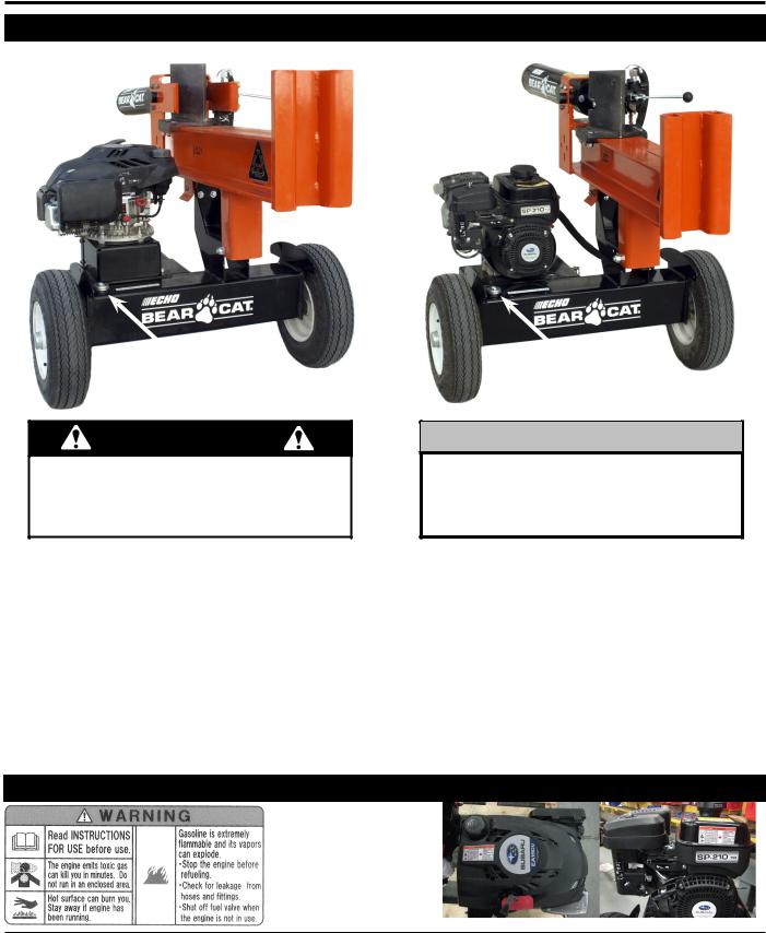
LS21 - 21 TON - 190cc SUBARU
LS27 - 27 TON - 210cc SUBARU
OWNER'S MANUAL
Manual P/N 77201-00
Rev. 010112
Companion to P/N 77241-00
SN Range: C01077C99999
ENGLISHFRANÇAIS SPNAOL
PORTUGUES

Before You Begin
DEAR ECHO BEAR CAT CUSTOMER
Thank you for purchasing a ECHO Bear Cat product. The ECHO Bear Cat line is designed, tested, and manufactured to give years of dependable performance. To keep your machine operating at peak efficiency, it is necessary to adjust it correctly and make regular inspections. The following pages will assist you in the operation and maintenance of your machine. Please read and understand this manual before operating your machine.
If you have any questions or comments about this manual, please call us toll-free at 1-800-247-7335.
If you have any questions or problems with your machine, please call or write your local authorized ECHO Bear Cat Dealer.
This document is based on information available at the time of its publication. ECHO Bear Cat is continually making improvements and developing new equipment. In doing so, we reserve the right to make changes or add improvements to our product without obligation for equipment previously sold.
PLEASE SEND US YOUR WARRANTY CARD
Awarranty card is included in your owner's kit packaged with your machine. Please take the time to fill in the information requested on the card. When you send your completed card to us, we will register your machine and start your coverage under our limited warranty.
FOR MACHINE SERVICE OR PARTS:
For service assistance, contact your nearest authorized ECHO Bear Cat dealer or the factory. For parts, contact your authorized dealer. The parts manual for your machine is available at http://bearcatproducts.com/main/support/ index_html. Your dealer will need to know the identification number of your machine to provide the most efficient service. See below for information on how to identify and record the identification number for your machine.
FOR ENGINE SERVICE OR PARTS:
Forengineserviceorparts,contactyournearestauthorized engine dealer. ECHO Bear Cat does not handle any parts, repairs or warranties for engines.
ORDERING PARTS
Only genuine ECHO Bear Cat replacement parts should be used to repair the machine. Replacement parts manufactured by others could present safety hazards, even though they may fit on this machine. Replacement parts are available from your ECHO Bear Cat dealer.
Provide the following when ordering parts:
The SERIAL NUMBER OR VIN of your machine. The PART NUMBER of the part.
The PART DESCRIPTION. The QUANTITY needed.
IDENTIFICATION NUMBER LOCATION
Your machine will have either a serial number or vehicle identification number (VIN). VINs are located on the left side of the trailer frame near the hitch. They are 17-digit numbers of the format: 5VJAA001XXWXXXXXX. Serial numbers are located on the machine body. They are
6-digit numbers.
Record your identification number in the space provided and on the warranty registration card.
SERIAL NUMBER OR VIN
HOW TO CONTACT ECHO BEAR CAT
ADDRESS |
PHONE |
HOURS |
||
|
|
|
|
|
237 NW 12th Street |
800.247.7335 |
|
Monday - Friday, |
|
P.O. Box 849 |
sales@bearcatproducts.com |
|||
701.282.5520 |
8 am to 5 pm |
|||
West Fargo, ND |
service@bearcatproducts.com |
|||
FAX: 701.282.9522 |
Central Time |
|||
58078 |
|
|||
|
|
|
||
|
|
|
|
*Original Instructions
© 2013, CRARY INDUSTRIES, ALL RIGHTS RESERVED. PRODUCED AND PRINTED IN THE U.S.A.

LIMITED WARRANTY
This warranty applies to all AG and Outdoor Power Equipment manufactured by Crary Industries.
Crary Industries warrants to the original owner each new Crary Industries product to be free from defects in material and workmanship, under normal use and service. The warranty shall extend 1 year from date of delivery for income producing (commercial) applications and 2 years from date of delivery for non-income producing (consumer) use of the product. The product is warranted to the original owner as evidenced by a completed warranty registration on file at Crary Industries. Replacement parts are warranted for (90) days from date of installation.
THE WARRANTY REGISTRATION MUST BE COMPLETED AND RETURNED TO CRARY INDUSTRIES WITHIN 10 DAYS OF DELIVERY OF THE PRODUCT TO THE ORIGINAL OWNER OR THE WARRANTY WILL BE VOID.
In the event of a failure, return the product, at your cost, along with proof of purchase to the selling Crary Industries dealer. Crary Industries will, at its option, repair or replace any parts found to be defective in material or workmanship. Warranty on any repairs will not extend beyond the product warranty. Repair or attempted repair by anyone other than a Crary Industries dealer as well as subsequent failure or damage that may occur as a result of that work will not be paid under this warranty. Crary Industries does not warrant replacement components not manufactured or sold by Crary Industries.
This warranty applies only to parts or components that are defective in material or workmanship.
This warranty does not cover normal wear items including but not limited to bearings, belts, pulleys, filters and chipper knives.
This warranty does not cover normal maintenance, service or adjustments.
This warranty does not cover depreciation or damage due to misuse, negligence, accident or improper maintenance.
This warranty does not cover damage due to improper setup, installation or adjustment. This warranty does not cover damage due to unauthorized modifications of the product.
Engines are warranted by the respective engine manufacturer and are not covered by this warranty.
Crary Industries is not liable for any property damage, personal injury or death resulting from the unauthorized modification or alteration of a Crary product or from the owner’s failure to assemble, install, maintain or operate the product in accordance with the provisions of the Owner’s manual.
Crary Industries is not liable for indirect, incidental or consequential damages or injuries including but not limited to loss of crops, loss of profits, rental of substitute equipment or other commercial loss.
This warranty gives you specific legal rights. You may have other rights that may vary from area to area.
CraryIndustriesmakesnowarranties,representationsorpromises,expressedorimpliedastotheperformance of its products other than those set forth in this warranty. Neither the dealer nor any other person has any authority to make any representations, warranties or promises on behalf of Crary Industries or to modify the terms or limitations of this warranty in any way. Crary Industries, at its discretion, may periodically offer limited, written enhancements to this warranty.
CRARY INDUSTRIES RESERVES THE RIGHT TO CHANGE THE DESIGNAND/OR SPECIFICATIONS OF ITS PRODUCTS AT ANY TIME WITHOUT OBLIGATION TO PREVIOUS PURCHASERS OF ITS PRODUCTS.
ENGLISH

|
TABLE OF CONTENTS |
|
DESCRIPTION |
PAGE |
|
SAFETY................................................................................................................. |
1 |
|
1.1 |
SAFETY ALERT SYMBOL...................................................................................... |
1 |
1.2 |
EMISSION INFORMATION.................................................................................... |
1 |
1.3 |
BEFORE OPERATING........................................................................................... |
1 |
1.4 |
OPERATION SAFETY............................................................................................ |
2 |
1.5 |
MAINTENANCE & STORAGE SAFETY................................................................. |
3 |
1.6 |
TOWING SAFETY.................................................................................................. |
3 |
1.7 |
SAFETY DECAL LOCATIONS................................................................................ |
4 |
ASSEMBLY............................................................................................................ |
5 |
|
2.1 |
FILLING HYDRAULIC FLUID................................................................................. |
5 |
2.2 |
ATTACHING THE HITCH........................................................................................ |
6 |
2.3 |
INSTALLING THE HYDRAULIC CYLINDER.......................................................... |
6 |
FEATURES & CONTROLS................................................................................... |
7 |
|
3.1 |
CONTROLS............................................................................................................ |
7 |
3.2 |
ENGINE CONTROLS............................................................................................. |
8 |
OPERATION.......................................................................................................... |
9 |
|
4.1 |
FILL THE FUEL TANK ........................................................................................... |
9 |
4.2 |
STARTING MACHINE............................................................................................ |
9 |
4.3 |
STOPPING MACHINE ........................................................................................... |
9 |
4.4 |
OPERATING THE LOG SPLITTER...................................................................... |
10 |
4.5 |
VERTICAL OPERATION....................................................................................... |
11 |
4.6 |
STORAGE MODE................................................................................................. |
12 |
4.7 |
TOWING THE LOG SPLITTER............................................................................ |
12 |
SERVICE & MAINTENANCE.............................................................................. |
13 |
|
5.1 |
MAINTENANCE SCHEDULE............................................................................... |
13 |
5.2 |
TRAILER SERVICE TIPS..................................................................................... |
13 |
5.3 |
FILLING HYDRAULIC FLUID............................................................................... |
14 |
5.4 |
CHANGING HYDRAULIC OIL FILTER................................................................. |
14 |
5.5 |
LUBRICATION...................................................................................................... |
14 |
TROUBLESHOOTING......................................................................................... |
15 |
|
SPECIFICATIONS............................................................................................... |
16 |
|
BOLT TORQUE............................................................................................................ |
17 |
|
OPTIONS............................................................................................................. |
18 |
|
iv |
LOG SPLITTER |
1 SAFETY
Section
1.1 SAFETY ALERT SYMBOL
The Owner/Operator’s manual uses this symbol to alert you of potential hazards. Whenever you see this symbol, read and obey the safety message that follows it. Failure to obey the safety message could result in personal injury, death or property damage.
DANGER
Indicates an imminently hazardous situation that, if not avoided, will result in death or serious injury.
The engine on your power equipment, like most outdoor power equipment, is an internal combustion engine that burns gasoline or diesel fuel (hydrocarbons). Therefore, your power equipment must be equipped with a spark arrester muffler in continuous effective working order. The spark arrester must be attached to the engine exhaust system in such a manner that flames or heat from the system will not ignite flammable material.
Failure of the owner/operator of the equipment to comply with this regulation is a misdemeanor under California law and may also be a violation of other state and/or federal regulations, laws, ordinances, or codes. Contact your local fire marshal or forest service for specific information about which regulations apply in your area.
Thestandardmufflerinstalledontheengineisnotequipped with a spark arrester. One must be added before using this machine in an area where a spark arrester is required by law. Contact the local authorities if these laws apply to you. See your authorized engine dealer for spark arrester options.
1.3 BEFORE OPERATING
WARNING
Indicates a potentially hazardous situation that, if not avoided, could result in death or serious injury.
CAUTION
Indicates a potentially hazardous situation that, if not avoided, may result in minor or moderate injury.
1.2 EMISSION INFORMATION
Under California
Law and the laws of
several |
other |
states, |
|
you |
are |
not |
permitted |
to |
operate an internal |
||
combustion engine using hydrocarbon fuels on any forest covered, brush covered or grass covered
land or on land covered with grain, hay or other flammable agricultural crops, without an engine spark arrester in continuous effective working order.
1.Read and understand this owner’s manual. Be completely familiar with the controls and the proper use of this equipment. Restrict the use of this power machine to persons who read, understand, and follow the warnings and instructions in this manual and on the machine.
2.Familiarize yourself with all of the safety and operating decals on this equipment and on any of its attachments or accessories.
3.Keep safety decals clean and legible. Replace missing or illegible safety decals.
4.Obtain and wear safety glasses and use hearing protection at all times when operating this machine.
5.Avoid wearing loose fitted clothing. Never operate this machine while wearing clothing with drawstrings that could wrap around or get caught in the machine.
6.Do not operate this machine if you are under the influence of alcohol, medications, or substances that can affect your vision, balance or judgement. Do not operate if tired or ill. You must be in good health to operate this machine safely.
ENGLISH
LOG SPLITTER |
1 |

SAFETY
7.Do not operate this equipment in the vicinity of bystanders. Keep the area of operation clear of all persons, particularly small children. It is recommended that bystanders keep at least 50 feet (15 meters) away from the area of operation.
8.Do not allow children to operate this equipment. Allow only adults to operate the log splitter. No one under the age of 18 should be allowed to operate the log splitter.
9.Use only in daylight or good artificial light.
10.Do not run this equipment in an enclosed area. Engine exhaust contains carbon monoxide gas, a deadly poison that is odorless, colorless and tasteless. Do not operate this equipment in or near buildings, windows or air conditioners.
11.Always use an approved fuel container. Do not remove gas cap or add fuel when engine is running. Add fuel to a cool engine only.
12.Do not fill fuel tank indoors. Keep open flames, sparks, smoking materials and other sources of combustion away from fuel.
13.Do not operate machine without shields in place. Failure to do so may cause serious injury or death.
14.Keep all guards, deflectors, and shields in good working condition.
15.Before inspecting or servicing any part of this machine, shut off the machine and make sure all moving parts have come to a complete stop. Disconnect the spark plug.
16.Check that all screws, nuts, bolts, and other fasteners are secured, tightened and in proper working condition before starting the machine.
17.Do not transport or move machine while it is operating or running.
7.Never operate the machine on slippery, wet, muddy, or icy surfaces. The location you choose should be solid, level, dry, and free from any tall grass, brush, or other interferences.
8.Always block machine wheels to prevent unintended movement and lock in either horizontal or vertical position.
9.Ensure the control lever is in the neutral detent position before starting the machine.
10.Keep the machine clear of debris and other accumulations. Immediately remove split wood from around the machine so you do not stumble over it.
11.During operation, hydraulic log splitters develop high fluid pressures. Fluid escaping through a pin hole opening can penetrate your skin and cause blood poisoning, gangrene, or death. Keep in mind the following instructions at all times:
a.Do not check for leaks with your hand.
b.Do not operate machine with frayed, kinked, cracked, or damaged hoses, fittings, or tubing.
c.Stop the engine and relieve hydraulic system. pressure before changing or adjusting fittings, hoses, tubing, or other system components.
d.Do not adjust the pressure settings of the pump or valve.
12.Leaks can be detected by passing cardboard or wood, while wearing protective gloves and safety glasses, over the suspected area. Look for discoloration of the cardboard or wood.
13.If injured by escaping fluid, see a doctor immediately. Serious infection or reaction can develop if proper medical treatment is not administered immediately.
1.4OPERATION SAFETY
1.This machine should be used for splitting wood only, do not use it for any other purpose.
2.Allow only one (1) person to load and operate the log splitter. If a helper is assisting in loading logs, never activate the control until the helper is a minimum of 10 feet away from the machine.
3.Always operate the log splitter from the operator zones specified in Section 4.4.
4.Do not use any body part, other than your hand, to operate the controls.
5.Keep hands and feet out of splitting area while machine is operating to avoid serious personal injury. Stop and allow machine to come to a complete stop before clearing obstructions.
6.Set up your work site so you are not endangering traffic and the public. Take great care to provide adequate warnings.
14.Do not attempt to split two logs with one positioned on top of the other.
15.Check the logs before splitting. Ensure there are no foreign materials, such as nails, present in the wood.
16.Do not attempt to split wood across the grain.
17.Always make sure that both ends of the log you are splitting are cut as square as possible.This will prevent the log from sliding out of position while under pressure. Logs should be 24 inches or shorter in length.
18.Do not load the log splitter while the splitting wedge is moving.
19.Hold the log by the sides when you are positioning it into the log splitter. Do not hold the log by the ends.
20.Always keep your fingers away from any cracks that open in the log during the splitting operation.
2 |
LOG SPLITTER |
SAFETY
21.When the ram of the log splitter is in the return mode, keep your hands off the machine—the log splitter is designed to automatically stop the ram when the cylinder is fully retracted.
22.Do not step across the log splitter while the engine is running.
23.Do not straddle or reach across the splitting area when operating the machine.
24.When splitting logs in the vertical position, stablize the log before engaging the control. Split as follows:
a.Place log on the end plate and turn until it leans against the beam and is stable.
b.When splitting extra large or uneven logs, the log must be stablized with wooden shims or split wood between the log and end plate or ground.
25.When at all possible, keep log splitter attached to a towing vehicle. If you are unable to do this, secure the hitch.
1.6TOWING SAFETY
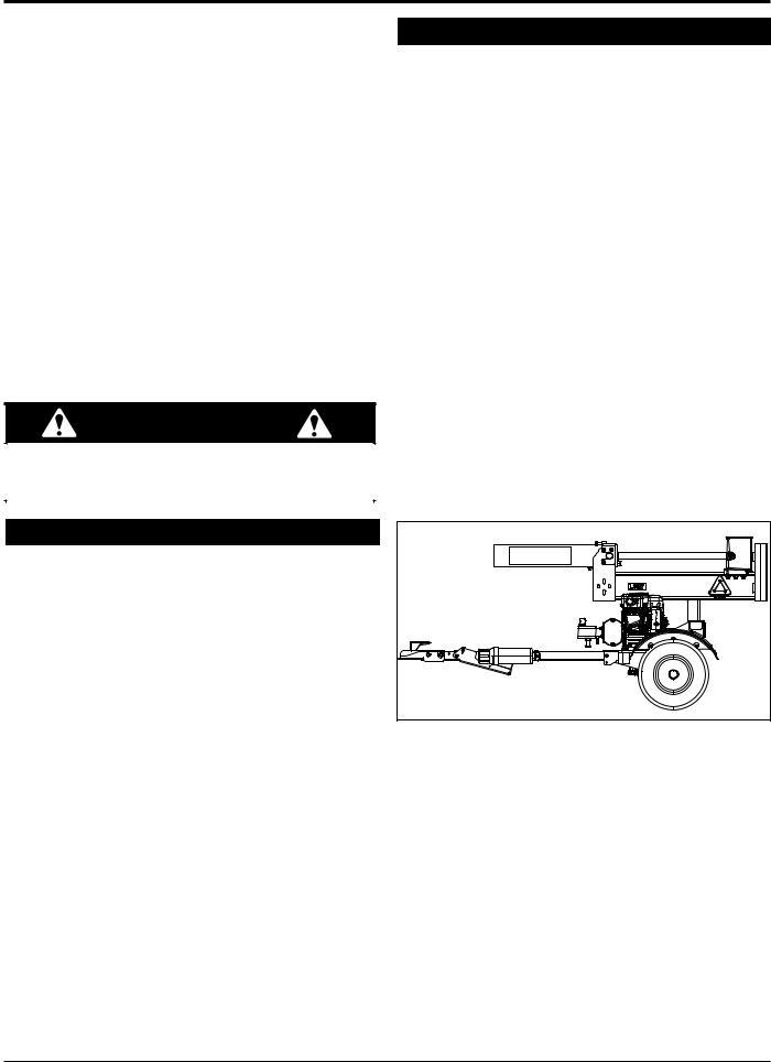
1.Ensure the log splitter is locked in the horizontal position before towing.
2.Extend log splitter ram all the way before towing to help maintain stability (see picture below).
3.Connect hitch safety chains. Tighten trailer hitch bolts. Do not attempt to tow the trailer if the vehicle is not equipped with a 2 inch ball.
4.Inflate tires to manufacturer’s specifications as stated on the tire sidewall.
5.Do not tow machine faster than 45 mph (72 kph).
6.Optimum towing performance can be achieved by maintaining a horizontal trailer hitch.
7.Make sure the jack stand is in the UP position during towing. Place the jack stand on a level surface and secure it in the DOWN position before using.
8.Never allow passengers to ride on the machine.
9.Shut off fuel supply when towing.
WARNING |
10. Towing laws may vary in different countries/regions/ |
|
|
|
states. It is recommended that you contact your local |
When splitting large and heavy material it is possible for |
motor vehicle department for any special regulations |
the log splitter to tip. Secure the stand before operating. |
that pertain to towing and know the laws of any country/ |
|
region/state you travel through. |
1.5MAINTENANCE & STORAGE SAFETY
1.Before inspecting, servicing, storing or changing an accessory, shut off the machine and make sure all moving parts have come to a complete stop. Disconnect the spark plug.
2.Replace any missing or unreadable safety decals. Refer to the safety decal section for part numbers.
3.Allow machine to cool before storing in an enclosure.
4.Store the machine out of reach of children and where fuel vapors will not reach an open flame or spark.
5.Never store this machine with fuel in the fuel tank inside a building where fumes may be ignited by an open flame or spark. Ignition sources can be hot water and space heaters, furnaces, clothes dryers, stoves, electric motors, etc.
6.Drain the fuel and dispose of it in a safe manner for storage periods of three months or more.
7.Replace any worn, cut, abraded, flattened or crimped hydraulic hoses.
8.Wear proper hand and eye protection when searching for a hydraulic leak. Instead of using your hands, use a piece of wood or cardboard as a backstop to identify a leak.
Correct towing configuration with ram extended and jack stand up. *Shown with optional fenders and trailer lights kit, PN 77200-00.
ENGLISH
LOG SPLITTER |
3 |

SAFETY
1.7 SAFETY DECAL LOCATIONS
Familiarize yourself with all of the safety and operational decals on the machine and the associated hazards. See the engine owner’s manual or contact the engine manufacturer for engine safety instructions and decals. Make certain that all safety and operating decals on this machine are kept clean and in good condition. Decals that need replacement must be applied to their original locations.
1 |
PN 12174 |
DO NOT OPERATE MACHINE WITHOUT |
|
SHIELDS IN PLACE. FAILURE TO DO SO MAY |
|
CAUSE SERIOUS INJURY OR DEATH. |
|
|
PN 12174 |
2 PN 14942-00
3 PN 18983-00
FEED ROLLER SUPPORT MUST BE SECURED IN THE UP POSITION PRIOR
TO SERVICING CHIPPER FEED AREA.
THE FEED ROLLER CAN FALL AND
CAUSE SEVERE BODILY HARM. CONSULT OWNERS MANUAL FOR
PROPER METHOD OF SECURING FEED ROLLER SUPPORT. LOWER FEED ROLLER BEFORE OPERATING CHIPPER.
4 PN 32158-00
265 |
585 |
READ AND UNDERSTAND YOU OWNERS MANUAL BEFORE OPERATING. IF OWNERS MANUAL WAS NOT INCLUDED OR YOU HAVE ANY QUESTIONS, PLEASE CALL 800.247.7335 OR 701.282.5520 (U.S.A.)
|
|
|
|
|
|
|
|
|
|
|
|
|
|
|
|
|
|
|
|
|
|
|
|
|
|
|
|
|
4.80-8 |
|
|
|
|
410 kPa, 60 psi |
|
|
|||||||||||||||
|
|
|
|
|
|
|
|
|
|
|
|
|
|
|
|
|
|
|
|
|
|
|
|
|
|
|
|
|
|
|
|
|
|
|
|
|
|
|
|
|
|
|
|
|
|
|
|
|
|
|
|
|
|
|
|
|
|
|
|
|
|
|
|
|
|
|
|
|
|
|
|
|
|
|
|
|
|
|
|
|
|
|
|
|
|
|
|
|
|
|
|
|
|
|
|
|
|
|
|
|
|
|
|
|
|
5 |
PN 36090-00 |
||
|
|
TURN |
ENGINE |
OFF |
BEFORE |
|
|
SERVICINGMACHINE.KEEPALLBODY |
|||
5 |
3 |
PARTS CLEAR OF THE SPLITTING |
|||
AREA WHILE SPLITTING WEDGE IS IN |
|||||
MOTION. THE HYDRAULIC CYLINDER |
|||||
|
|
AND SPLITTING WEDGE CAN CAUSE SEVERE BODILY HARM. |
|||
|
|
BEFORE OPERATING LOG SPLITTER, CONSULT OWNERS MANUAL |
|||
|
|
FOR PROPER OPERATION AND MAINTENANCE TECHNIQUE. |
|||
4 |
1 |
2 |
Model LS21 Shown
4 |
LOG SPLITTER |
2 ASSEMBLY
Section
2.1 FILLING HYDRAULIC FLUID
ENGLISH
LS21 Hydraulic Fluid Fill Location
ATTENTION
LOG SPLITTERS ARE NOT SHIPPED WITH HYDRAULIC FLUID IN THE SYSTEM. FILLING THE MACHINE WITH THE CORRECT AMOUNT OF HYDRAULIC FLUID IS NECESSARY BEFORE USE.
LS27 Hydraulic Fluid Fill Location
NOTE
AN IN-DEPTH SET OFASSEMBLY INSTRUCTIONS IS AVAILABLE AT THE END OF THIS MANUAL.
Your log splitter will need to be filled with hydraulic fluid before in can be operated. The entire hydraulic system needs to be filled for the hydraulic ram to function correctly.
The amount of fluid for proper hydraulic ram operation is as follows:
LS21: 4 gallons (15.1 liters) LS27: 4.25 gallons (16.1 liters)
The hydraulic tank is located in the back of the machine.
See hydraulic fluid fill location photos above.
Check the fluid level with the dipstick before each use.
SUBARU WARNING LABEL
Check the fluid on level ground with the jack stand in the down position. The hydraulic pump requires premium hydraulic fluids containing high quality rust, oxidation, and foam inhibitors. These include premium turbine oils, API CD engine oils per SAE J183, M2C33F or G automatic transmission fluids meeting Allison C-3 or Caterpillar TO- 2, and certain specialty agricultural tractor fluids.
DO NOT OVERFILL.
FILL THE HYDRAULIC FLUID TANK WITH THE RAM RETRACTED.
For use in the U.S. and Canada. Affix the warning label suited to the region from among the enclosed warning labels. Affix in the locations shown on the right.
LS21 LS27
LOG SPLITTER |
5 |
2.2 ATTACHING THE HITCH
3 |
5 |
|
9 |
8 |
2 |
10 |
|
6 |
7 |
5 |
3 |
1 |
4 |
1.Place coupler(8) on end of hitch pole(9), insert two 1/2 x 3" bolts(6) through the coupler holes and Secure with 1/2 centerlock nuts.
2.Position a safety chain(2) on each side of the hitch in the hole behind the coupler(8). Insert 3/8 x 3-1/4" bolt(7) with washers and nylock nuts through the top link of the safety chains and hole behind the coupler.
3.Attach lanyard(1) to jack stand with 1/4 x 3/4" bolt(4), washer, and nut. Then attach lanyard to hitch pin(3).
4.Attach the jack stand(10) to the hitch pole(9) using 3/8 x 3" bolt(5) and nylock nut. Swing jack stand up into the stored position and secure by using the hitch pin(3) and cotter pin from step 3.
5.Place hitch pole in position at the front of the machine and mount using 3/8 x 3" bolt(5), nylock nut, hitch pin(3) and cotter pin as shown above.
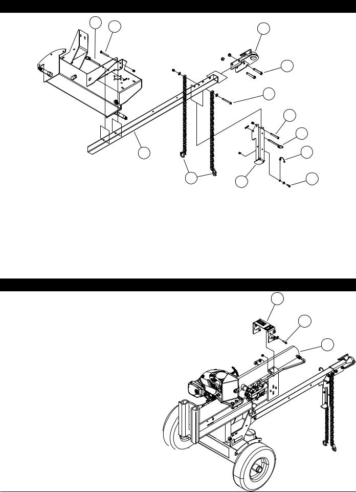
2.3INSTALLING THE HYDRAULIC CYLINDER
The log splitter is shipped with the hydraulic cylinder moved forward on the main beam. To install the hydraulic cylinder:
1. Remove the two 5/16 x 1" bolts(1) that connect the cylinder cradle (2) to the main beam and discard.
2. Slide the hydraulic cylinder(3) and valve assembly back until the ports at the ram end of the cylinder rest in the notches of the main beam.
3. Secure the hydraulic cylinder by reinstalling the 

 cylinder cradle(2) from step 1. Use six 5/16 x 1"


 bolts(1), washers, and nuts from the owners kit.


2 |
1 |
3 |
6 |
LOG SPLITTER |
3FEATURES & CONTROLS
Section
3.1 CONTROLS
Understanding how your machine works will help you achieve the best results when using your machine. The following descriptions define the features and controls of your machine.
1.Hitch safety chains: Safety chains are used during towing to prevent the machine from completely separating from the tow vehicle in the event the coupler detaches from the tow vehicle. Cross the safety chains under the hitch and connect to the towing vehicle.
2.Hitch jack: Always have in UP position and clear from the ground when machine is moving. When machine is in use, place in DOWN position on a level surface.
3.Hydraulic pump: The pump provides hydraulic power to the system.
4.Hydraulic fluid tank: The hydraulic pump requires premium hydraulic fluids containing high quality rust, oxidation, and foam inhibitors. These include premium turbine oils,API CD engine oils per SAE J183, M2C33F or G automatic transmission fluids meetingAllison C-3 or Caterpillar TO-2, and certain specialty agricultural tractor fluids.
5.Splitting area: Place logs to be cut in the splitting area.
Keep all body parts clear of the splitting area when the splitting wedge is in motion.
6.Splitting wedge: The splitting wedge is connected to the ram of the hydraulic cylinder.
7.Log splitter control lever: Push the lever toward the splitting area to extend the ram of the hydraulic cylinder. Pull the lever away from the splitting area to retract the ram. The lever will automatically return to the neutral position when the ram is fully retracted.
8.Hydraulic cylinder: Extend and retract the ram of the hydraulic cylinder with the log splitter control lever.
7 |
6 |
5 |
|
8 |
4 |
3 |
ENGLISH
2
1 |
LOG SPLITTER |
7 |
FEATURES & CONTROLS
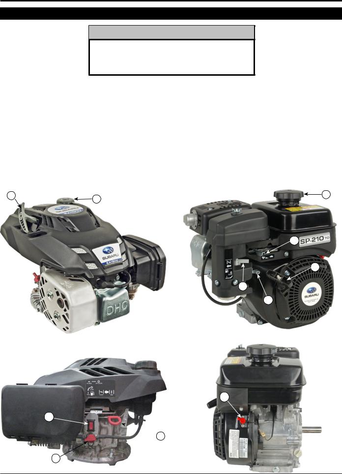
3.2 ENGINE CONTROLS
NOTE
FOR THE SPECIFIC STARTING, OPERATING AND
SERVICE INFORMATION PERTAINING TO YOUR
EXACT ENGINE MODEL, ALWAYS CONSULT THE
ENGINE OWNER'S MANUAL FIRST.
1.Engine choke: Use when starting a cold engine. To use, push the lever to the left. Gradually turn off as the engine warms. Full choke may not be necessary when starting a warm engine. In this case, partial or no choke may work best.
2.Fuel cut-off switch: Push lever to the ON position to start and run engine. Push lever to OFF position when engine is not in use and during transport.
3.Engine throttle (LS27 only): This changes engine speed. Push lever all the way to the fast position for full throttle operation. Push the opposite way for engine idle. Push all the way to the slow position to shut engine off. Refer to engine manual for further engine operating instructions.
4.Engine switch (if equipped): Turn to ON position to start and run engine. To stop, turn to OFF position.
5.Starter cord: To start, pull the cord until light resistance is felt and then pull briskly.
6.Fuel tank: Fill only with fuel types specified in your engine owner's manual.
5 |
6 |
6 |
|
|
3
5
1
2
LS27 - 211cc Subaru
LS21 - 189cc Subaru
4
4
 1
1
2
8 |
LOG SPLITTER |
Loading...