

Page 1

Service Manual
Fuller Medium Heavy Transmissions
TRSM0201
October 2007
Page 2

For parts or service call us
Pro Gear & Transmission, Inc.
1 (877) 776-4600
(407) 872-1901
parts@eprogear.com
906 W. Gore St.
Orlando, FL 32805
Page 3

Page 4

Model Designations...........................................................................................................................2
Description........................................................................................................................................3
Specifications....................................................................................................................................4
Lubrication.........................................................................................................................................5
Conversion to Overdrive.....................................................................................................................6
Clutch Shaft Replacement..................................................................................................................6
General Precautions for Disassembly.................................................................................................6
Detailed Disassembly Instructions......................................................................................................7
Exploded Views
Drive Gear............................................................................................................................................8
Countershafts.....................................................................................................................................11
Reverse Idler Shaft............................................................................................................................11
Reverse Idler Gear and Shaft.............................................................................................................14
Mainshaft...........................................................................................................................................14
Tailshaft.............................................................................................................................................14
Tailshaft and Rear Bearing Cover.......................................................................................................17
Shifting Bar Housing.........................................................................................................................17
Inspection..........................................................................................................................................17
Torque Ratings...................................................................................................................................21
Gasket Location.................................................................................................................................21
Preventative Maintenance Check Chart..............................................................................................25
General Precautions for Reassembly.................................................................................................25
Detailed Reassembly Instructions......................................................................................................25
Tool Reference...................................................................................................................................25
Gear Chart for Part Numbers.............................................................................................................26
Page 5

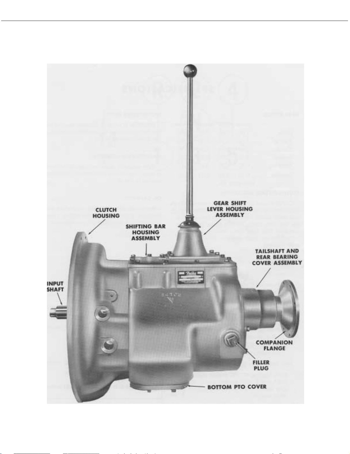
DESCRIPTION
CUTAWAY OF FIVE SPEED
TWIN-COUNTERSHAFT TRANSMISSION
2
Page 6

MODEL DESIGNATIONS
MODEL DESIGNATIONS
= Twin Countershaft Type
T
= Used as a letter, denotes overdrive model
O
= 900 lbs. ft. capacity rating
09
= Five speeds
05
“A”, “B”. etc.
= Following numbers indicates a specific set of ratios
Since the models in the T-905 series are identical in construction, references in this manual apply to all models unless
stated otherwise. This includes models not listed above which may have other ration combinations, designated by letters following the numerals.
PART NUMBERS SHOWN IN THIS MANUAL ARE SUBJECT TO CHANGE AND APPLY ONLY AT TIME OF PRINTING.
3
Page 7
DESCRIPTION
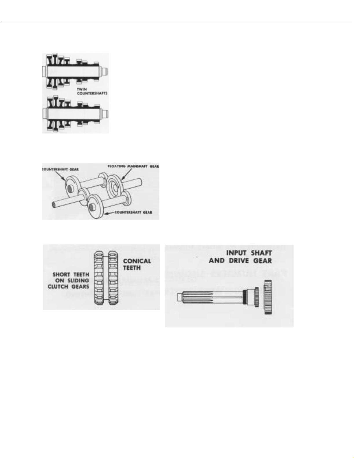
The T-905 model transmissions have five forward speeds and one reverse speed, and
are designed for heavy duty vehicles. These models are of twin countershaft design
which divides the torque equally between shafts and gears, providing a high capacity to
weight ratio.
The countershafts, identical except for the PTO gears, are short and bearings are of a
relative low capacity due to the split torque principle. All gears have spur type teeth.
The mainshaft floats free, receiving only minor radial loads. Mainshaft vertical displacement to conform to clutched gear position is allowed by rod-like springs which resist
float to right or left.
The mainshaft gears are not jounalled to the mainshaft, but are
located axially by washers and held in position by rotation of the
countershaft gears; this eliminates the need for bushings and
sleeves. Because of equal tooth loading on each side of gear,
pressure is reduced and gear face width can be narrowed. Gears
are clutched by internal splines in hubs of gears. The sliding
clutch gears with short, conical clutching teeth provide shorter
and easier shifts.
The input shaft and drive gear are not integral, thus they can be
changed individually.
4
Page 8
DESCRIPTION
5
Page 9

SPECIFICATIONS
SPECIFICATIONS
SPEEDOMETER DRIVE
GEAR RATIOS
T-905A T-905B TO-905A TO-905B
Fifth
Fourth
Third
Second
First
Reverse
1.00 1.00 0.65 0.86
1.54 1.16 1.00 1.00
2.38 2.04 1.54 1.76
3.75 3.75 2.44 3.23
6.35 6.35 4.12 5.47
6.48 6.48 4.21 5.58
SEE PAGE 68
Clutch Release Mechanism
Clutch release bearing carrier, release bearing, extended
front bearing cover, release yoke and pedal shafts furnished with transmission for use with single or two plate,
push type clutches. Flat type front bearing cover furnished for use with single or two plate, pull type clutches.
Power Take-Off
Openings
Bottom: SAE standard heavy-duty type, short length.
Right Side: SAE standard regular-duty type, short
length.
Provision is made in the rear bearing cover for the installation of speedometer gears and the attachment of cable.
MAGNETIC OIL CLEANERS
Two magnetic discs are installed in bottom of case to
catch and hold metallic particles deposited in the oil.
OIL CAPACITY
Approximately 22 pints, depending on inclination of
transmission and engine. Twenty-two pints is a zero
degree measurement.
Nominal torque rating
Clutch housing size
Weight, with grey iron case
Length
From face of clutch housing to rear shoulder
of mainshaft 27-19/32 inches
From face of clutch housing to front of
companion flange hub
900 foot-pounds
SAE No. 1 or 2
478 pounds
24-23/32 inches
PTO Drive Gear
Bottom: A 47-Tooth, 6/8 pitch gear on the left counterhshaft.
Right Side: A 45-Tooth, 6/8 pitch gear on the right
countershaft.
PTO Drive Gear Speeds
Both turning at .533 engine speed on T-905A and T905B models; and at .820 engine speed on TO-905A,
and .619 on TO-905B models.
6
Page 10

SPECIFICATIONS (SHIFTING DIAGRAMS)
Shifting Diagram for T-905 Model Transmissions
Shifting Diagram for TO-905 Model Transmissions
7
Page 11

LUBRICATION
Proper lubrication procedures are the key to a good allround maintenance program. If the oil is not doing its
job, or if the oil level is ignored, all the maintenance procedures in the world are not going to keep the transmission running or assure long transmission life.
Oil is important, because here are some of the things it
must do:
• Provide a protective film - to protect surface of
heavily loaded parts such as gear teeth and bearings,
thus preventing metal to metal contact which causes
scoring, scuffing and seizure.
• Act as a coolant - to dissipate heat.
LUBRICATION CHANGE AND INSPECTION
HIGHWAY USE
First 3,000-5,000 miles
(4827 - 8045 Km)
Every 5,000 miles
(8045 Km)
Every 50,000 miles
(80,450 Km)
First 30 hours Change transmission oil on new units.
First 40 hours Inspect oil level. Check for leaks.
Change transmission oil on new units.
Inspect oil level. Check for leaks.
Change transmission oil.
OFF-HIGHWAY
• Have sufficient fluidity - to follow, coat and cushion
all loaded surfaces.
• Be chemically stable - to withstand heat and agitation without separation, gumming-up, oxidizing or
corroding.
• Be non-foaming - to prevent excessive foam and
increased volume under severe conditions.
• Be free of sediment and water - to prevent sludge
and rust.
Fuller Transmissions are designed so that the internal
parts operate in a bath of oil circulated by the motion of
gears and shafts. Grey iron parts have built-in channels
where needed, to help lubricate bearings and shafts.
Thus, all parts will be amply lubricated if these procedures are closely followed:
1. Maintain oil level. Inspect regularly.
2. Change oil regularly.
3. Use the correct grade and type of oil.
Every 500 hours Change transmission oil where severe
Every 1,000 hours Change transmission oil (Normal off-
Change Oil Filter Element, If So Equipped, At Each Oil Change.
RECOMMENDED LUBRICANTS
TYPE GRADE TEMPERATURE
Heavy Duty Engine Oil MIL-L2104C, or MIL-L-46152, or
API-SE, or API-CC
Mineral Gear Oil SAE 90
Heavy Duty Engine Oil MIL-L2104C, or MIL-L-46152, or
API-SE, or API-CC
Special Recommendation - For extreme cold weather where
temperature is consistently below 0°F.
Heavy Duty Engine Oil MIL-L2104C, or MIL-L-46152, or
API-SE, or API-CC
dirt conditions exist.
highway use).
ON-HIGHWAY VEHICLES
SAE 50 or
SAE 40
SAE 30
SAE 80W
OFF-HIGHWAY
SAE 50 or
SAE 40
SAE 30
SAE 20W Below 0°F.
Above + 10°F.
(-12.5°C.)
Below + 10°F.
Above + 10°F.
Below + 10°F.
Above + 10°F.
Below + 10°F.
(-18°C.)
4. Buy from a reputable dealer.
Miscellaneous Lubricants
O-Rings and Surfaces - Dowing Corning #200 Silicone,
30,000 Centistokes. Union Carbide L-45 Silicone, 30,000
Centistokes.
8
Page 12
Lubrication
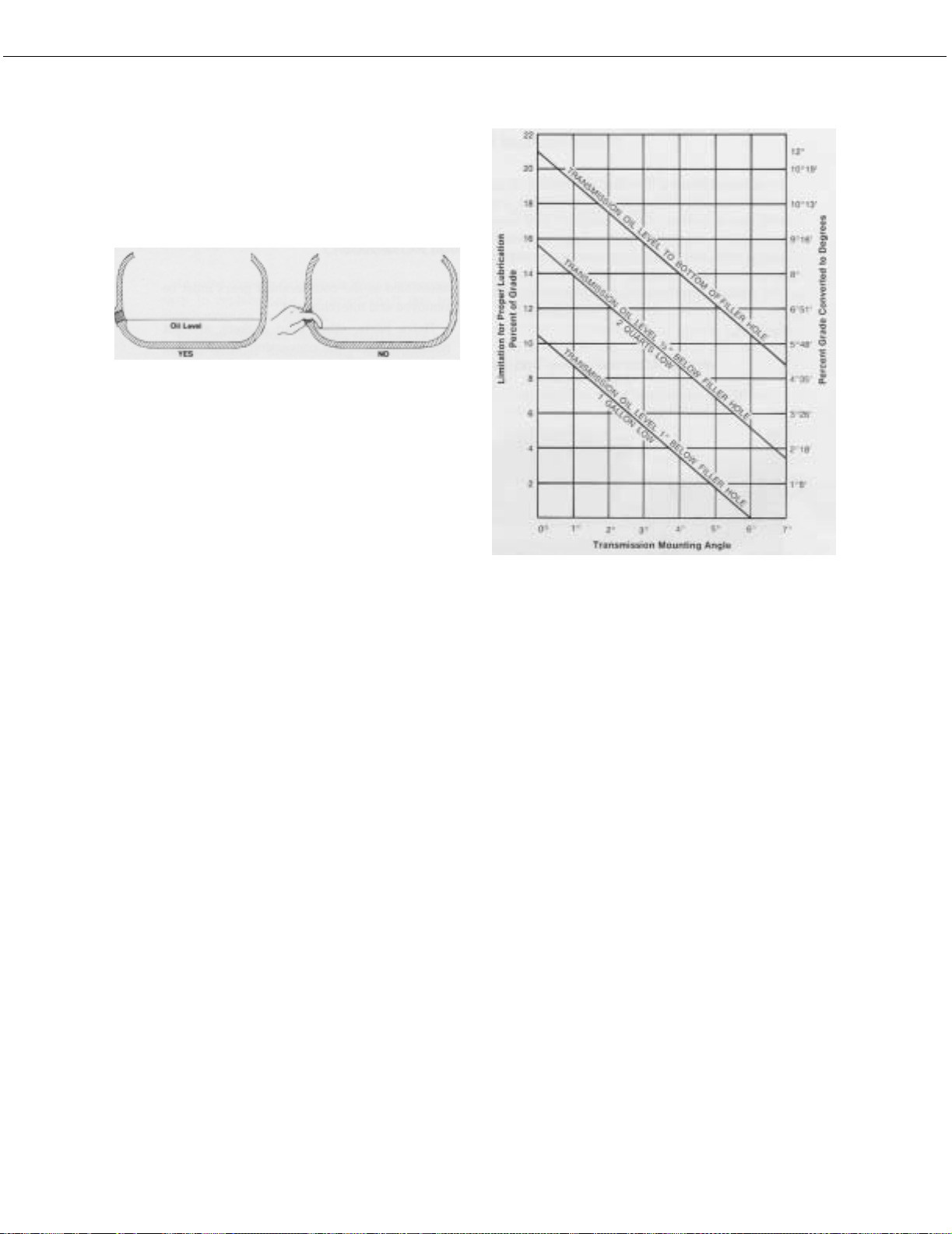
Proper Oil Level
Make sure oil is level with filler opening. Because you can
reach oil with your finger does not mean oil is at proper
level.
Draining Oil
Drain transmission while oil is warm. To drain oil, remove
the drain plug at bottom of case. Clean the drain plug
before re-installing.
Refilling
Clean area around filler plug and remove plug from side
of case. Fill transmission to the level of the filler opening.
If transmission has two filler openings, fill to level of rear
opening on single countershaft models; fell to level of
both openings on twin countershaft models.
The exact amount of oil will depend on the transmission
inclination and model. In every instance, fill to the level of
the filler opening.
Do not over fill. This will cause oil to be forced out of the
case through mainshaft openings.
External cooler kits are available to keep the transmission
operating temperature under 250°F. when the conditions
described above are encountered.
If the transmission operating angle is more than 12
degrees, improper lubrication can occur. The operating
angle is the transmission mounting angle in the chassis
plus the percent of upgrade (expressed in degrees).
Adding Oil
It is recommended that types and brands of oil should
not be intermixed because of possible incompatibility.
Operating Temperature
It is important that the transmission operating temperature does not exceed 250°F. (120°C.) for an extended
period of time. Operating temperatures above 250°F. will
cause breakdown of the oil and shorten transmission life.
The following conditions in any combination can cause
operating temperatures of over 250°F: (1) Operating consistently at roadspeeds under 20 MPH, (2) High engine
RPM, (3) High ambient temperature, (4) Restricted air
flow around transmission, (5) Exhaust system too close
to transmission, (6) high horsepower, over-drive operation. High operating temperatures may require more frequent oil changes.
The above chart illustrates the safe percent of upgrade on
which the transmission can be used with various chassis
mounting angles. For example: If you have a 4 degree
transmission mounting angel, then 8 degrees (or 14 percent of grade) is equal to the limit of 12 degrees. If you
have a 0 degree mounting angle, the transmission can be
operated on a 12 degree (21 percent) grade.
Anytime the transmission operating angle of 12 degrees
is exceeded for an extended period of time the transmission should be equipped with an oil pump or cooler kit to
insure proper lubrication.
Note on the chart the effect low oil levels can have on
safe operating angles. Allowing the oil level to fall ½”
below the filler plug hole reduces the degree of grade by
approximately 3 degrees (5.5)
PROPER LUBRICATION LEVELS ARE IMPORTANT!
9
Page 13
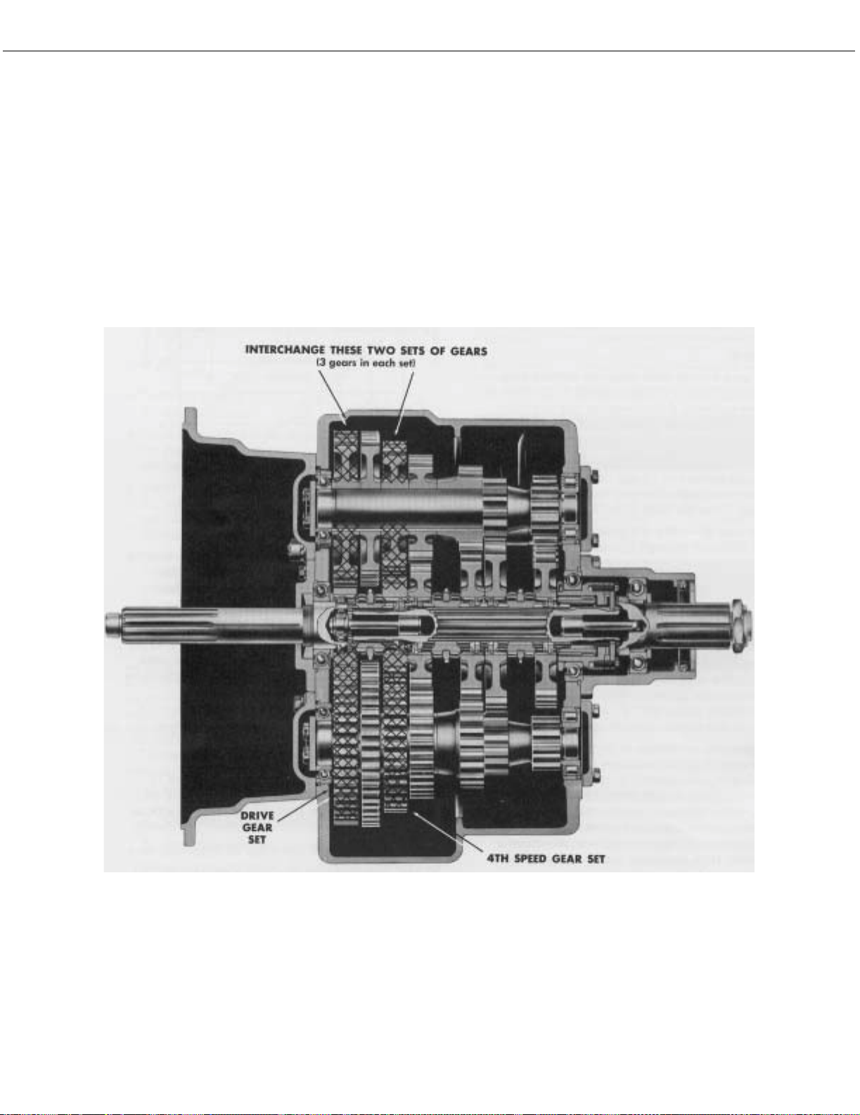
CONVERSION TO OVERDRIVE
TO CONVERT FROM T-905A To
TO-905A, or T-905B to TO-905B
To convert from a T-905A or T-905B to an overdrive
model TO-905A or TO-905B the 4th speed gear on the
mainshaft and mating gears, one on each countershaft,
are interchanged with the main drive gear and mating
countershaft drive gears.
The transmission must be completely disassembled as
the countershaft gears must be removed and interchanged.
Extra parts, other than gaskets are not needed to make
the conversion. A new drive gear bearing nut may be
needed as this part may be damaged during removal.
10
Page 14

SPECIAL PROCEDURE FOR CHANGING THE CLUTCH (INPUT) SHAFT
In some case it may be necessary to remove only the
input shaft due to clutch wear on the splines. In these
cases, the input shaft can be removed without disassembling the transmission other than removing the shift bar
housing. Removal of the clutch housing is optional. The
following is the detailed procedure:
Disassembly
1. Remove the gear shift lever housing and shift bar
housing from transmission.
2. Remove the front bearing cover.
3. Remove the drive gear bearing nut.
4. Move the drive gear assembly as far forward as possible and remove the drive gear bearing.
5. Remove the spacer from input shaft.
6. From the front, remove the snap ring from ID of
drive gear.
7. Peen nut into milled slot in shaft.
8. Re-install front bearing cover, shifting bar housing
and gear shift lever housing.
NOTE: The above instructions are for changing the
input shaft only. To change the drive gear,
removal of the mainshaft and countershaft
bearings is necessary.
7. Pull the input shaft forward and from splines of drive
gear.
Reassembly
1. Install new input shaft into splines of drive gear just
far enough to expose snap ring groove in ID of drive
gear.
2. Install snap ring in ID of drive gear.
3. Install spacer on shaft.
4. IMPORTANT - To prevent damaging the front quill
when installing bearing, move the 4th & 5th speed
sliding clutch gear forward to contact end of input
shaft in hub of drive gear. Block between rear of sliding clutch and front of the 4th speed gear. When
installing bearing this will hold input shaft away from
quill.
5. Install drive gear bearing on shaft and into case bore,
making sure blocking remains in place.
6. Remove blocking from mainshaft and install the
drive gear bearing nut, left-hand thread. Use Loctite
sealant on threads of nut and shaft.
11
Page 15

DISASSEMBLY PRECAUTIONS
GENERAL PRECAUTIONS FOR DISASSEMBLY
Important: Read this section before starting the detailed disassembly procedures.
It is assumed in the detailed disassembly instructions
that the transmission lubricant has been drained and the
transmission has been removed from the chassis.
Removal of the gear shift lever housing assembly is
included in the detailed instructions; however, this
assembly must also be removed from transmission
before removing unit from vehicle.
Follow each procedure closely in each section, making
use of both the text and pictures.
1. BEARINGS - Carefully wash and relubricate all bearings as removed and protectively wrap until ready
for use. Remove bearings with pullers designed for
this purpose.
2. SNAP RINGS - Remove snap rings with pliers
designed for this purpose. Rings removed in this
manner can be reused.
3. INPUT SHAFT - The clutch or input shaft can be
removed without removing the countershafts or
mainshaft (Refer to Page 11).
4. CLEANLINESS - Provide a clean place to work. It is
important that no dirt or foreign material enters the
unit during repairs. The outside of the unit should be
carefully cleaned before starting the disassembly.
Dirt is abrasive and can damage bearings.
5. WHEN DRIVING - Apply force to shafts, housings,
etc., with restraint. Movement of some parts is
restricted. Do not apply force after the part being
driven stops solidly. Use soft hammers and bars for
all disassembly work.
12
Page 16

DETAILED DISASSEMBLY INSTRUCTIONS
DETAILED DISASSEMBLY INSTRUCTIONS
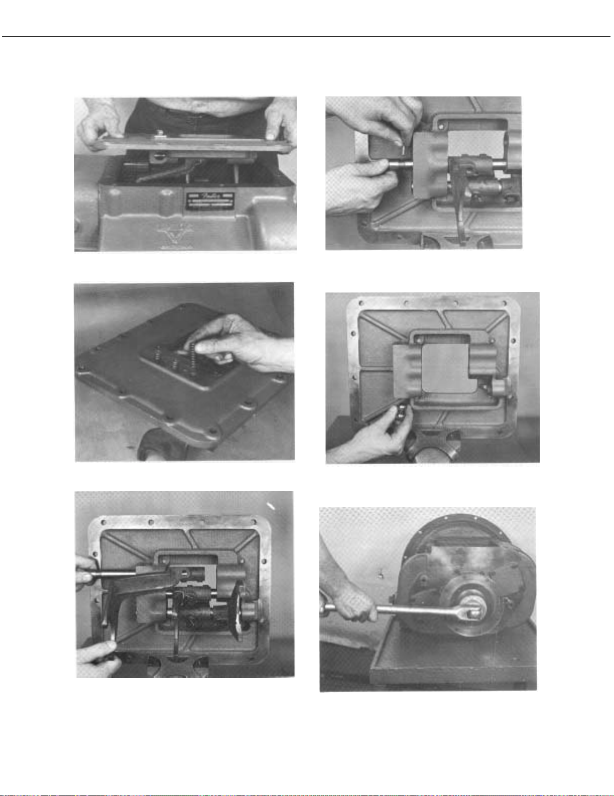
A. To Remove and Disassemble the Gear Shift Lever
Housing Assembly
1. Turn out the four capscrews and lift the gear
shift lever housing, or remote control housing,
from the shifting bar housing (See Illustration
1).
2. Remove the ball grip and rubber dust cover
from the gear shift lever.’
3. Mount the assembly in a vise with the large bottom opening upwards.
4. Free the tension spring by twisting a heavy
screwdriver between spring and housing, forcing spring from its seat in housing (See Illustration 2).
#1 - Lifting gear shift lever housing from shifting bar
housing.
5. Remove the tension spring from housing.
6. Withdraw the tension spring washer and gear
shift lever out through bottom housing (See
Illustration 3).
7. Remove nut and lockwasher from pivot pin.
8. Remove pivot pin by forcing it inward and
through wall of housing.
#2 - Removing the gear shift lever tension spring from
under lugs cast in housing.
#3 - Removing washer and gear shift lever from housing.
13
Page 17
DISASSEMBLY
#4 - Lifting the shifting bar housing from transmission.
#5 - Removing shifting bar tension springs.
#7 - Removing interlock pin from neutral notch in the 2nd
& 3rd speed shifting bar.
#8 - Two interlock balls are located in front boss, one
between each bar.
I#6 - Pulling the 4th-5th speed shifting bar from housing.
#9 - Turning companion flange nut from output shaft.
14
Page 18

DISASSEMBLY
B. To Remove the Shifting Bar Housing Assembly
1. Turn out the attaching capscrews.
2. Jar to break the gasket seal and lift the shifting
bar housing from transmission (See Illustration
#4).
C. To Disassemble the Shifting Bar Housing Assembly
NOTE: Lay all parts on a clean bench in the order in
which they are removed to facilitate reassembly. Keep bars not being removed in the neutral position or interlock parts will lock bars.
1. Turn out the two capscrews and remove the tension spring cover from top of housing.
2. Remove the three tension springs from bores in
housing (See Illustration #5).
3. Tilt housing and remove the tension balls
installed under the springs.
4. Place the housing in a vise with the left side up;
the long bar will be at the bottom.
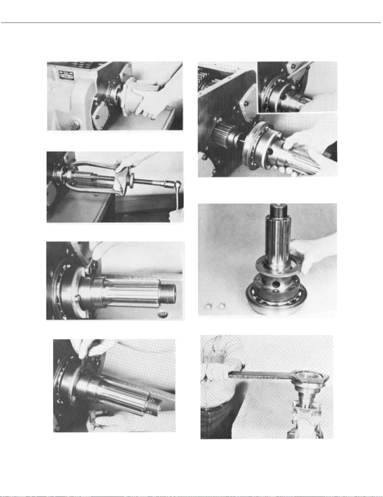
D. To Remove the Companion Flange or Yoke
1. Lock the mainshaft by engaging two speeds
with the mainshaft sliding clutch gears.
2. Turn the elastic stop nut from the output shaft
(See Illustration #9).
3. Pull the flange or yoke from splines of the
tailshaft.
E. To Remove and Disassemble the Rear Bearing
Cover Assembly
1. Turn out the attaching capscrews from the rear
bearing cover.
2. Pry the bearing cover evenly to the rear to
unseat from tailshaft bearing (See Illustration
#10).
5. Cut lockwire and remove lockscrews from each
bar just prior to its removal.
6. Move the top, 4th-5th speed shifting bar to the
front and out of housing, removing shifting yoke
from bar (See Illustration #6).
7. Move the center, 2nd-3rd speed shifting bar to
the front and out of housing, removing the shifting yoke from bar. As the neutral notch in bar
clears housing boss, remove the small interlock
pin from bore in neutral notch (See Illustration
#7).
8. Move the bottom, 1st-Reverse speed shifting
bar to the front and out of housing, removing
the shifting yoke and block from bar.
9. Two interlock balls will fall from interlock ball
opening in front boss as the last bar is removed
(See Illustration #8).
#10 - Prying rear bearing cover evenly to rear.
3. Remove the bearing cover from tailshaft (See
Illustration #11).
4. Remove the speedometer gear, or replacement
spacer, and the bearing washer from tailshaft or
from cover.
5. Pull the outer bearing from tailshaft. (This bearing may remain in cover; in this case, move the
bearing evenly forward and from cover) See
Illustration #12.
6. Remove the oil seal from cover if necessary.
15
Page 19
DISASSEMBLY
#11 - Removing rear bearing cover from tailshaft.
#12 - Pulling the tailshaft outer bearing.
#15 - Removing tailshaft from case bore. Start assembly
to the rear by prying evenly against bearing snap ring.
#13 - Removing capscrews from flat keys.
#14 - Removing flat keys from tailshaft. These keys maintain relative position of mainshaft to tailshaft.
#16 - Removing key spacer ring from tailshaft.
#17 - Turning bearing nut from tailshaft, left-hand thread.
16
Page 20
DISASSEMBLY
F. To Remove and Disassemble the Tailshaft Assem-
bly
1. Cut lockwire and turn out the two 5/16” capscrews from the two flat keys (See Illustration
#13).
2. Remove the two flat keys from bores in tailshaft.
These keys maintain the position of the mainshaft in relation to tailshaft (See Illustration
#14).
3. Move the tailshaft evenly to the rear and from
case bore. Moving the mainshaft assembly to
the rear will start moving tailshaft from bore
(See Illustration #15).
4. Remove the splined coupling gear from mainshaft, or from pocket in tailshaft.
5. Turn out the 5/16” capscrews and remove the
key spacer ring from tailshaft (See Illustration
#16).
6. Remove the bearing nut from tailshaft, left-hand
thread (Illustration #17).
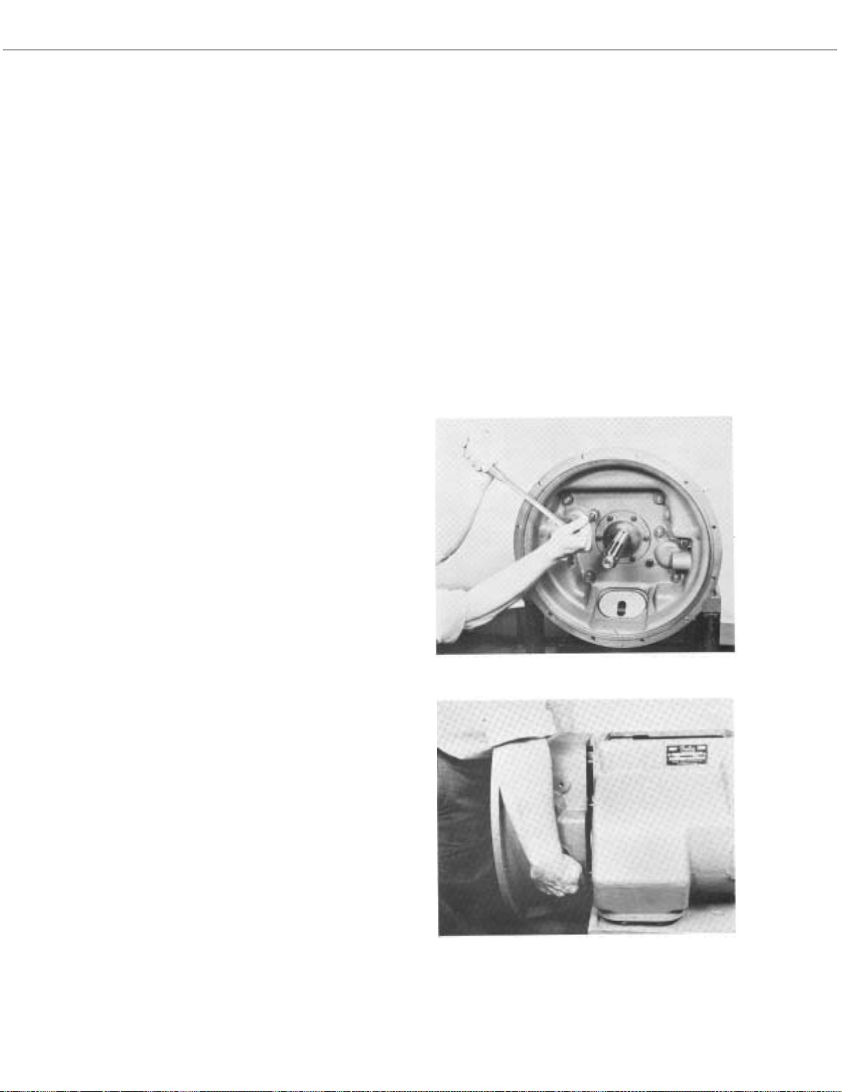
G. To Remove the Clutch Housing
NOTE: The clutch housing can be removed at any
time during transmission disassembly. However, it must be removed BEFORE the two
countershafts can be removed.
1. Remove the clutch release mechanism if the
transmission is so equipped.
2. Turn out the four bolts and remove the six nuts
and lockwashers from studs at front of case
(See Illustration #18).
3. Break gasket seal and pull clutch housing from
case (See Illustration #19).
7. Press the front bearing from tailshaft.
#18 - Turning attaching bolts from clutch housing.
#19 - Removing clutch housing from case.
17
Page 21
DISASSEMBLY
#20 - Removing snap ring from ID of the mainshaft
reverse gear.
#21 - Removing lockplate from left reverse idler shaft.
#23 - Removing left reverse idler gear and the two thrust
washers from case.
#24 - Removing rear bearing cover from right countershaft.
#22 - Removing left reverse idler shaft with impact puller.
#25 - Removing bearing retainer plat from front of right
countershaft.
18
Page 22

DISASSEMBLY
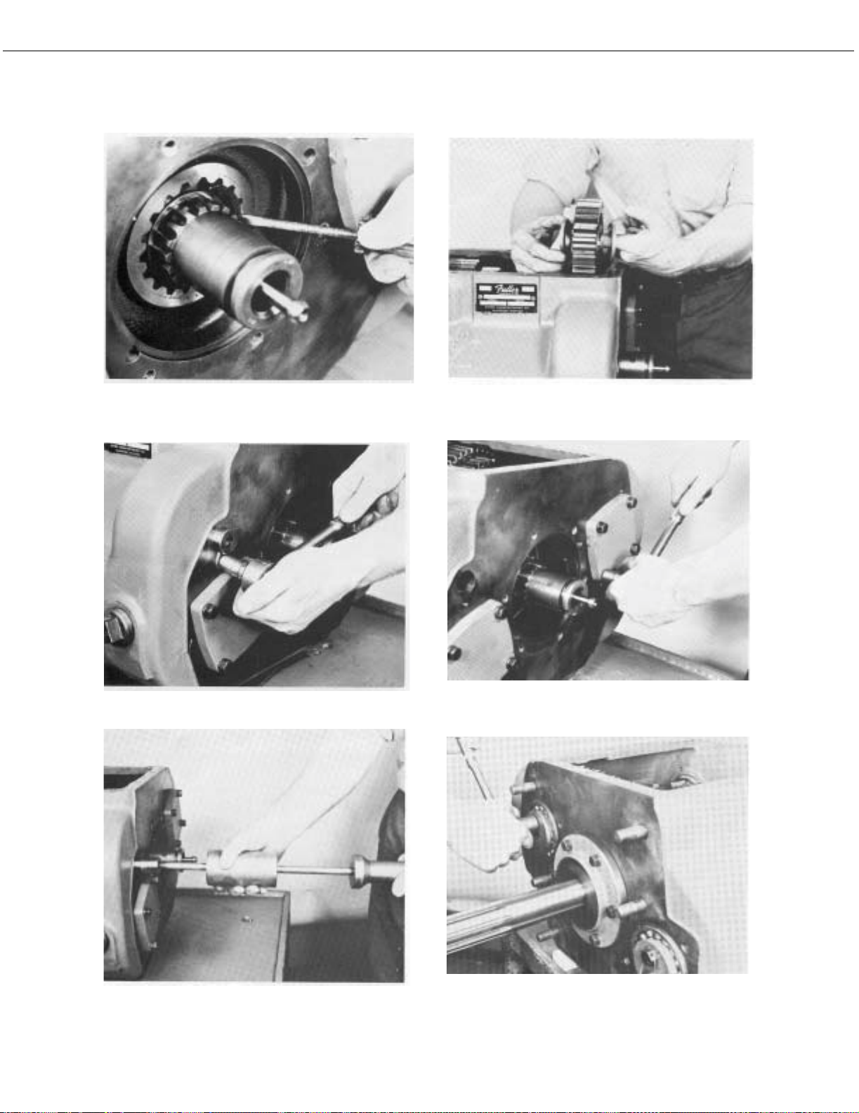
H. To Remove the Left Reverse Idler Gear
NOTE: The left reverse idler gear must be removed in
order to remove the mainshaft assembly.
1. Move the mainshaft assembly forward as far as
possible and the mainshaft reverse gear to the
rear against case.
2. Remove the snap ring from ID of the mainshaft
reverse gear (See Illustration #20).
3. Move the 1st-Reverse sliding clutch gear and
the reverse gear as far forward as possible on
the mainshaft.
4. Turn out capscrew at rear of transmission and
remove the lock plate from slot in the idler shaft
(See Illustration #21).
5. Use impact puller to withdraw the idler shaft
from case (See Illustration #22).
6. Remove the reverse idler gear and the two
thrust washers from case (See Illustration #23).
7. Remove inner race of bearing from gear bore.
8. Press needle bearing from gear bore.
4. Use puller to remove rear bearing from shaft. A
snap ring can be installed in rear bearing groove
to facilitate pulling if groove type puller is not
available (See Illustration #27).
5. Use soft bar and mall to move right countershaft
forward to partially unseat front bearing (See
Illustration #28).
6. Remove front bearing from countershaft (See
Illustration #29).
9. Remove plug from idler shaft if necessary.
I. To Remove Bearings from Right Countershaft
NOTE: In order to remove the mainshaft assembly it
will be necessary to move the right countershaft by removing bearings.
1. Turn out capscrews and remove rear bearing
cover from right countershaft (See Illustration
#24).
2. Cut lockwire, turn out the two capscrews and
remove bearing retainer plate from front of right
countershaft (See Illustration #25).
3. Use soft bar and mall to move the right countershaft to the rear until snap ring groove in rear
bearing is exposed. Do not unseat shaft from
front bearing (See Illustration #26).
#26 - Moving right countershaft to the rear to expose rear
bearing. DO NOT UNSEAT FRONT BEARING FROM
SHAFT.
#27 - Pulling rear bearing from right countershaft.
19
Page 23

DISASSEMBLY
#28 - Moving right countershaft forward to expose front
bearing.
#31 - Removing short key from keyway in mainshaft.
#29 - Pulling from bearing from right countershaft.
#30 - Removing mainshaft assembly from case.
#32 - Turning the 4th-speed gear washer to align with
mainshaft splines.
#33 - Removing 4th-speed gear, spacer and washer from
shaft.
20
Page 24

DISASSEMBLY
J. To Remove the Mainshaft Assembly
11. Remove the 1st and 2nd speed gears wi
w
ashers and spacers from mainshaft (See Illus-
tration #37).
th
1. With right countershaft moved toward wall of
case, pull the mainshaft to the rear, life fron
sh
aft and remove assembly from
llustration #30).
I
K. To Disassemble the Mainshaft Assembly
NOTE: When removing washers, spacers and gears,
note their location to facilitate reassembly.
Keep washers and spacers with the gear from
which they were removed; there is one spacer
and one washer for each gear. The spacers
have external splines to engage gear splines;
the washers have internal splines to engage
mainshaft splines.
1. Remove the Reverse gear from mainshaft.
2. Remove the 4th-5th speed sliding clutch from
front of shaft.
3. Remove the short key from keyway near front
sh
aft. This key locks the 4th speed gear w
n position (See Illustration #31).
i
case (See
t of
asher
12. Remove the quill bearing snap ring.
13. Pull the quill bearing from quill. Do not move
quill as relative position of quill and mainshaft
must be retained (See Illustration #38).
#34 - Removing key-retaining snap ring from mainshaft.
of
4. Turn the 4th speed gear washer, located in hub
of 4th speed gear, to align with splines in mainshaft (See Illustration #32).
5. Pull gear forward to remove the washer, spacer
and gear from shaft (See Illustration #33).
6. Remove the 3rd speed gear, washer and spacer
from shaft.
7. Remove the 2nd-3rd speed sliding clutch gear
from shaft.
8. Remove the key retaining snap ring from sl
n
ear rear of mainshaft (See Illustration #34).
9. Pull the long key from mainshaft (See Illustration #35).
10. Remove the Reverse gear spacer, washer an
the 1st-Rever
(See Il
se sliding clutch gear from sh
lustration #36).
ot
d
aft
#35 - Pulling the long key from mainshaft.
21
Page 25

DISASSEMBLY
#36 - Removing spacer, washer and sliding clutch from
mainshaft.
#39 - Lifting the right countershaft from case.
#37 - Removing remaining gears, spacers, and washers
from mainshaft.
#38 - Pulling the quill bearing.
#40 - Removing the right reverse idler shaft with impact
puller.
#41 - Removing the right reverse idler gear and two
thrust washers from case.
22
Page 26

DISASSEMBLY
L. To Remove the Right Countershaft Assembly
1. Move the countershaft to the rear, move front
sh
aft toward center of case and lift the assembl
fro
m case (See Illustration #39)
M. To Remove the Right Reverse Idler Gear
1. Turn out capscrews at rear of transmission
ove the lock plate from slot in the idler shaft.
rem
2. Use impact puller to withdraw the idler
fro
m case (See Illustration #40).
3. Remove the reverse idler gear and the tw
ust washers from case (See Illustration #41).
thr
4. Remove inner race of bearing from gear bore.
5. Press the needle bearing from gear bore.
N. To Remove the Left Countershaft Assembly
1. Turn out capscrews and remove the rear bearing
cover from left countershaft (See Illustration
#42).
of
y
and
shaft
o
#42 - Removing rear bearing cover from left countershaft.
2. Cut lockwire, turn out the two capscrews and
remove the bearing retaining plate from fron
countershaft (See Illustration #43).
left
3. Use soft bar and mall to move the counters
far
enough to the rear to expose the snap ring
groove in rear bearing.
4. Use puller to remove rear bearing from
ap ring can be installed in rear bearing groo
sn
facilitate pulling if groove type puller is no
to
lable (See Illustration #44).
avai
5. Use soft bar and mall to move countershaft forward to partially unseat front bearing. Keep r
o
f shaft centered in bore with block (See Illus-
tration #45).
6. Remove front bearing from countershaft and
case bore.
7. Move the countershaft to the rear, lift front of
shaft to the center and up to remove from
lustration #46).
(See Il
t of
haft
shaft. A
ve
t
ear
case
#43 - Removing bearing retainer plate from front of left
countershaft.
23
Page 27

DISASSEMBLY
#44 - Pulling rear bearing from left countershaft.
#45 - Moving left countershaft forward to unseat from
bearing.
#47 - Pressing drive gear, PTO gear, 4th speed gear and
3rd speed gear from countershaft.
#48 - Pressing 2nd speed gear from countershaft.
#46 - Removing left countershaft from case.
#49 - Turning capscrews from front bearing cover.
24
Page 28

DISASSEMBLY
O. To Disassemble the Countershaft Assemblies
NOTE: Both countershafts are disassembled in the
same manner.
1. Press the drive gear, PTO gear, 4th speed gear
and 3rd speed gear from countershaft. Use caution when pressing gears as it is necessary to
press these gears off in a cluster of four (See
Illustration #47).
2. Press the 2nd speed gear from countershaft
(See Illustration #48).
3. Remove the two keys from countershaft if necessary.
4. Remove the roll pin from countershaft if necessary.
P. To Remove the Drive Gear Assembly
#50 - Removing snap ring from drive gear bearing.
1. Turn out capscrews from the front bearing cover
(See Illustration #49).
2. Use soft bar and mall from inside case to move
the drive gear assembly forward as far as possible and remove the bearing cover.
3. Remove the snap ring from bearing (See Illustration #50).
4. Move the assembly to the inside of case and lift
through top of case (See Illustration #51).
#51 - Lifting gear assembly out through top of case.
25
Page 29

DISASSEMBLY
Q. To Disassemble the Drive Gear Assembly
1. Place the assembly in a vise, pilot end up.
#52 - Relieving bearing nut where peened into shaft.
2. Relieve the bearing nut where peened in
(See Il
lustration #52).
3. Turn the bearing nut from shaft, left-hand thr
(See Il
lustration #53).
4. Using the rear face of the drive gear as a b
unt the assembly in a press, and pr
mo
aft through the gear to unseat bearing from
sh
shaft. This will free the bearing, spacer and g
rm shaft (See Illustration #54).
fo
5. Remove snap ring from ID of drive gear if necessary.
to shaft
ead
ase,
ess the
ear
#53 - Turning drive gear bearing nut from shaft, left-hand
thread.
#54 - Pressing shaft through drive gear and bearing.
26
Page 30

DRIVE GEAR ASSEMBLY
27
Page 31

COUNTERSHAFT ASSEMBLY
28
Page 32

REVERSE IDLER SHAFT AND GEAR ASSEMBLY GRAPH-
ICS
29
Page 33

REVERSE IDLER GEAR AS ASSEMBLED IN CASE
30
Page 34

MAINSHAFT ASSEMBLY
31
Page 35

TAILSHAFT ASSEMBLY
32
Page 36

TAILSHAFT AND REAR BEARING COVER ASSEMBLY
33
Page 37

SHIFTING BAR HOUSING ASSEMBLY 35Inspection
34
Page 38

Before reassembling the transmission, the individual
parts should be carefully checked to eliminate those
damaged from previous service. This inspection procedure should be carefully followed to insure the maximum
of wear life from the rebuilt unit.
The cost of a new part is generally a small fraction of the
total cost of downtime and labor, should the use of a
questionable part make additional repairs necessary
before the next regularly scheduled overhaul.
Recommended inspection procedures are set forth in the
following checklist:
A. Bearings
1. Wash all bearings in clean solvent. Check balls,
rollers and races for pits and spalled areas.
Replace bearings which are pitted or spalled.
2. Lubricate bearings
which are not spalled
or pitted and check
for axial and radial
clearances. Replace
bearings with excessive clearances.
3. Check fits of bear-
ings in case bores. If
outer races turn
freely in the bores,
the case should be
replaced.
B. Gears
1. Check operating gear teeth for pitting on the
tooth faces. Gears with pitted teeth should be
replaced.
2. Check all engaging gear teeth. Gears with teeth
worn, tapered or reduced in length from clashing in shifting should be replaced.
3. Check axial clearances of gears. Where excessive clearance is found, check gear snap ring,
washer, spacer and gear hub for excessive wear.
Maintain .005 - .012 axial clearance of mainshaft forward speed gears, .005 minimum on
reverse gear.
C. Splines
1. Check splines on all shafts for wear. If sliding
clutch gears, companion flange or clutch hubs
have worn into the sides of the splines, the
shafts in this condition should be replaced.
D. Thrust Washers
1. Check surfaces of all
thrust washers. Washers
scored or reduced in
thickness should be
replaced.
E. Reverse Gear and Shaft
1. Check bearing sleeve for wear from action of
roller bearings.
F. G ray I ron P a rt s
1. Check all gray iron parts for cracks and breaks.
Replace or repair
parts found to be
damaged. Heavy
casting may be
welded or brazed
providing the cracks
do not extend into
bearing bores or
bolting surfaces.
G. Clutch Release Parts
1. Check clutch release parts. Replace yokes worn
at cam surfaces
and bearing carrier worn at contact pads.
2. Check pedal
shafts. Replace
those worn at
bearing surfaces.
H. Shifting Bar Housing Assembly
1. Check yokes and blocks for wear at pads and
lever slot. Replace worn parts.
2. Check yokes for alignment.
3. Check yokes for
excessive wear;
replace worn
yokes.
4. Check lockscrews in yokes
and blocks.
Tighten and
rewire those
found loose
Page 39

TORQUE RATINGS
Recommended torque ratings, location and thread sizes
of capscrews and nuts are listed below. Capscrew length
are given for reference purposes as a guide to installation
at proper locations.
CAPSCREWS
Correct torque application is extremely important to
assure long transmission life and dependable performance. Over-tightening or under-tightening can result in
a loose installation and, in many instances, eventually
causing damage to transmission gear, shafts or bearings.
Do not torque capscrews dry.
Location
P.T.O. Cover, Small
Tailshaft Key Spacer Ring
Tailshaft Key
Reverse Idler Shaft Lock
Poppet Spring Cover
Front Bearing Cover
Shifting Bar Housing
Gear Shift Lever Housing
Mainshaft Rear Bearing Cover
Countershaft Rear Bearing Cover
P.T.O. Cover, Large
Clutch Housing to Case
Countershaft Front Bearing Retainer
Clutch Housing to Case
Drive Gear
Tailshaft Front Bearing
Companion Flange or Yoke
NUTS
Thread Size
and Length
3/8-16 x ¾
5/16-24 x 5/8
5/16-24 x 1
3/8 -16 x 1
3/8-16 x1-¼
3/8-16 x1-¼
3/8-16 x1-¼
3/8-16 x1-¼
3/8-16 x1-¼
½-13 x 1-¼
½-13 x 3-¼
5/8-18
2-1/8-16
3-17/32-16
1-½-18
Qty.
6
2
2
2 5/16-18 x ¾ 25-35
2
6
13
4
6
8
8 7/16-14 x 1-¼ 50-65
2
2
4 ½-20 x1 100-115
6
1
1
1
Torque Rating
Foot-Pound
20-25
35-45
90-100
(70-75)*
180-190 (170-175)*
250-300
250-300
400-450
LOCATION OF GASKETS
Seat gaskets with shellac on part to be installed. Use new
gaskets throughout when reassembling transmission.
Gaskets are located on the following parts:
• P.T.O. Cover, Small
• P.T.O. Cover, Large
• Gear Shift Lever Housing
•Clutch Housing
• Front Bearing Cover
• Countershaft Rear Bearing Covers
• Shifting Bar Housing
• Mainshaft Rear Bearing Cover
37
Page 40

PREVENTATIVE MAINTENANCE CHECK CHART
38
Page 41

PREVENTATIVE MAINTENANCE CHECK CHART
CHECKS WITHOUT PARTIAL
DISASSEMBLY OF CHASSIS OR CAB
1. Clutch Housing Mounting
a. Check all capscrews in bolt circle of clutch hous-
ing for looseness.
2. Clutch Pedal Shaft and Bores
a. Pry upward on shaft to check wear.
b. If excessive movement is found, remove clutch
release mechanism and check bushings in bores
and wear on shafts.
3. Clutch Release Bearing
a. Remove hand hole cover and check radial and
axial clearance in release bearing.
b. Check relative position of thrust surface of
release bearing with thrust sleeve on push type
clutches.
4. Capscrews and Gaskets
a. Check all capscrews, especially those on PTO
covers and rear bearing covers for looseness
which would cause oil leakage.
b. Check PTO opening and rear bearing covers for
oil leakage due to faulty gasket.
5. Gear Lubricant
a. Change at specified service intervals.
b. Use only gear oils as recommended (See Lubrica-
tion Section).
6. Filler and Drain Plugs
8. Gear Shift Lever Housing Assembly
a. Remove the gear shift lever housing assembly
from transmission.
b. Check tension spring and washer for set and
wear.
c. Check the gear shift lever pivot pin and pivot pin
slot for wear.
d. Check bottom end of gear shift lever for wear and
check slot of yokes and blocks in shift bar housing for wear at contact points with shift lever.
CHECKS WITH DRIVE LINE DROPPED
9. Universal Joint Companion Flange Nut
a. Check for tightness. Tighten to recommended
torque.
CHECKS WITH UNIVERSAL JOINT COMPANION FLANGE
REMOVED
10. Splines on Output Shaft
a. Check for wear from movement and chucking
action of the universal join companion flange.
11. Mainshaft Rear Bearing Cover
a. Check oil seal for wear.
12. Output Shaft
a. Pry upward against output shaft to check radial
clearance in mainshaft rear bearing.
a. Remove filler plug and check level of lubricant at
specified intervals. Tighten filler and drain plugs
securely.
7. Gear Shift Lever
a. Check for looseness and free play in housing. If
lever is loose in housing, proceed with Check #8.
39
Page 42

GENERAL PRECAUTIONS FOR REASSEMBLY
IMPORTANT: Read this section before starting the
detailed reassembly procedures.
Make sure that interiors of case and housings are clean.
It is important that dirt be kept out of transmission during
reassembly. Dirt is abrasive and can damage polished
surfaces of bearings and washers. Use certain precautions, as listed below, during reassembly.
1.GASKETS - Use new gaskets
throughout the transmission as it
is being rebuilt. Make sure all gaskets are installed, as omission of
gasket can result in oil leakage or
misalignment of bearing covers
(See “Location of Gaskets” heading).
2. CAPSCREWS - To prevent oil leakage, use shellac on
all capscrews. See torque rating chart for recommended torque.
3. ASSEMBLY - Refer to the assembly illustration,
pages 27-34, as a guide to reassembly.
4. INITIAL LUBRICATION - Coat all thrust washers and
splines of shafts with Lubriplate during installation
to provide initial lubrication, preventing scoring and
galling.
5. AXIAL CLEARANCES - Maintain the following axial
clearances:
6.BEARINGS - Use of flangedend bearing drivers is recommended for the installation of
bearings. These drivers apply
equal force to both races of
bearing, preventing damage to
balls and races and maintaining
correct bearing alignment with shaft and bore. If
tubular or sleeve type driver is used, apply force only
to inner race.
7. UNIVERSAL JOINT COMPANION FLANGE - Pull the
companion flange tightly into place with the mainshaft nut, using 450-500 ft. lbs. of torque. Make sure
the speedometer gear is not used, a replacement
spacer of the same width must be used. Failure to
pull the yoke or flange tightly into place will permit
the shaft to move axially with resultant damage to
rear bearing.
Mainshaft Forward Speed Gears ...............................005”-.011
Mainshaft Reverse Speed Gear ..................................005-.023
Reverse Idler Gear ..................................................... .011-.032
Mainshaft................................................................... .002-.008
40
Page 43

DETAILED REASSEMBLY INSTRUCTIONS
A. To Reassemble the Drive Gear Assembly
1. Install snap ring in ID of drive gear (See Illustration #55).
2. Install the drive gear on shaft, engaging internal
splines of gear with teeth on shaft, snap ring of
gear towards the front (See Illustration #56).
3. Install drive gear spacer on shaft and against
gear (See Illustration #57).
4. Press the drive gear bearing on shaft, shield to
the front (See Illustration #58).
5. Clean threads of drive gear and nut and apply grade
AVV Loctite (See Illustration #59).
6. Install the bearing nut on shaft, left-hand thread,
with 250-300 ft. lbs of torque (See Illustration #60).
NOTE: If torque wrench is not available, torque can
be approximated by multiplying the pounds of
pull time the length of wrench handle. For
example: If there are 150 pounds of pull on a
wrench with a two-foot handle, multiply 150 x
2, which equals 300 ft. lbs. of torque. Ordinary pull scales can be used to measure
pounds of pull.
#55 - Installing snap ring in ID of drive gear.
#56 - Installing drive gear on input shaft, engaging gear
splines with shaft splines.
#57 - Installing spacer on shaft.
#58 - Drive gear bearing installed on shaft.
41
Page 44

REASSEMBLY
#59 - Applying Loctite sealant to threads of drive gear
nut.
#60 - Installing drive gear bearing nut, left-hand thread.
#62 - Drive gear teeth marked for timing, two adjacent
teeth plus two adjacent teeth directly opposite.
#63 - Installing the drive gear assembly through top of
case.
#61 - Peening nut into the two milled slots of shaft.
#64 - Installing snap ring on drive gear bearing.
42
Page 45

1. Clean threads of drive gear and nut and apply grade
A
VV Loctite (See Illustration #59).
2. Install the bearing nut on shaft, left-hand thread
w
ith 250-300 ft. lbs of torque (See Illustration #60).
NOTE: If torque wrench is not available, torque can
be approximated by multiplying the pounds of
pull time the length of wrench handle. For
example: If there are 150 pounds of pull on a
wrench with a two-foot handle, multiply 150 x
2, which equals 300 ft. lbs. of torque. Ordinary pull scales can be used to measure
pounds of pull.
,
B. To Reassemble the Countershaft Assemblies
NOTE: Except for the power take-off gears, the coun-
tershafts are identical.
1. Install roll pin in bore located in keyway of countershaft (See Illustration #66).
3. Peen the nut into the two milled slots of
llustration #61).
I
4. IMPORTANT: Mark the drive gear for timing. Ma
y two adjacent teeth on the drive gear, then
an
tw
o adjacent teeth which are directly opposite
fi
rst set marked (See Illustration #62).
A. To Install the Drive Gear Assembly
1. Remove the snap ring from drive gear bearing.
2. Insert the drive shaft from inside case through
front bore. Seat the drive gear bearing in
ore and move assembly forward until sn
b
ng groove in bearing is exposed (See Illustra-
ri
tion #63).
3. Install snap ring in bearing groove (See Illustration #64).
4. Seat bearing in case bore.
5. Install the drive gear bearing cover, aligning oil
return slot in cover with oil return bore in
ighten capscrews securely (See Illustration
T
#65).
shaft (See
mark
case
rk
the
#65 - Installing the drive gear bearing cover.
ap
case.
#66 - Installing roll pin in countershaft.
43
Page 46

REASSEMBLY
#67 - Installing keys in countershaft.
#70 - Pressing the power take-off gear on countershaft.
#68 - Pressing the 2nd speed gear on countershaft.
#69 - Pressing the 3rd speed gear on countershaft
#71 - Pressing the drive gear on countershaft.
#72 - Marking timing tooth on countershaft drive gear.
Tooth is aligned with keyway and is stamped with an “O”.
44
Page 47

REASSEMBLY
2. Install the short key in countershaft, tapered end
against roll pin.
3. Install the long key in keyway in countershaft
(See Illustration #67).
4. Align keyway in gear with keys in shaft and
press the 2nd speed gear on shaft, long hub
towards front of shaft (See Illustration #68).
5. Press the 3rd speed gear on countershaft, long
hub towards 2nd speed gear (See Illustration
#69).
6. Press the 4th speed gear on countershaft.
7. Press the power take-off gear on countershaft,
bullet nose teeth towards rear of shaft (See
Illustration #70).
NOTE: The left countershaft assembly has a 47-tooth
PTO gear; the right assembly has a 45-tooth
gear. Mark each assembly as “right” and
“left”.
8. Press the drive gear on countershaft (See Illustration #71).
9. IMPORTANT: Mark countershaft drive gears for
timing. On the drive gear of each countershaft,
mark tooth that is aligned with keyway in gear;
this tooth will be stamped with an “O” (See
Illustration #72).
C. To Time and Install the Left Countershaft Assembly
1. Place the left countershaft assembly with the
47-foot PTO gear into position in case (See
Illustration #73).
2. Center front of left countershaft in bore (See
Illustration #74).
Illustration #73 - Placing left countershaft into position in
case.
Illustration #74 - Centering left countershaft in front bore
with wood block.
45
Page 48

REASSEMBLY
#75 - Timing tooth on countershaft meshed with timing
teeth on drive gear.
#78 - Installing bearing retainer plate on front of left
countershaft.
#76 - Installing rear bearing on left countershaft.
#77 - Installing front bearing on left countershaft.
#79 - Installing rear bearing cover.
#80 - Installing plug in reverse idler shaft.
46
Page 49

REASSEMBLY
3. Mesh the marked tooth on countershaft drive
g
ear with two teeth marked on the main dri
g
ear (See Illustration #75).
4. Center countershaft in rear bore and install
r bearing on shaft and into case bore. Bear-
rea
ing can be started by installing partially on shaft
before seating in bore (See Illustration #76).
5. Install front bearing on countershaft and into
case bore (See Illustration #77).
6. Install the bearing retainer plate on fron
co
untershaft, tighten and wire capscrew
secu
rely (See Illustration #78).
7. Install the rear bearing cover, tighten capscrew
rely (Illustration #79).
secu
D. To Install the Right Reverse Idler Gear
1. Install plug in oil channel in idler
I
llustration #80).
2. Press needle bearing into bore of reverse g
ler gear.
id
shaft (See
t of
s
ve
the
ear
E. To Place Right Countershaft in Position
1. Lower the countershaft assembly through top
case,
small end through the rear countershaft
bore in case (See Illustration #82).
2. Move countershaft forward and into corr
osition, aligning timing tooth on countersha
p
ith those on main drive gear. Do not install
w
bearings.
s
of
ect
ft
3. Place inner race of bearing in gear.
4. Place a thrust washer on each side of gear, oil
slots to gear.
5. Place the reverse gear and the two thrust washers into position in case.
6. Thread the idler shaft through bore in rear of
case, washers and gear. Make sure slot in idle
aft is aligned with lockplate capscrew bore in
sh
case (See Illustration #81).
7. Install the lockplate in slot in idler shaft. Tigh
cap
screw securely.
ten
#81 - Threading the right reverse idler shaft through
reverse idler gear and the two thrust washers.
r
#82 - Placing the right countershaft into position in case.
Do not install bearings.
47
Page 50

REASSEMBLY
#83 - Drawing showing correct dimensions for mainshaft
quills.
#84 - Installing quill bearing snap ring.
#86 - Installing reverse gear washer on shaft and inserting key through keyway and washer.
#85 - Installing snap ring in ID of mainshaft gear.
#87 - Installing the 1st-Reverse sliding clutch gear on
shaft.
48
Page 51

REASSEMBLE
F. To Reassemble the Mainshaft Assembly
NOTE: Mainshaft should have quills assembled, one
in each end. In case it is necessary to install
quills, exact dimensions must be held
between end of shaft and end of quill (See
Illustration #83)
1. Place the mainshaft in a vise, pilot end up, so
that keyway in shaft is exposed for insertion of
key.
2. Install quill bearing on front quill. Do not move
quill.
3. Install bearing snap ring on quill (See Illustration #84).
4. Install snap rings in ID of all mainshaft gears
except the reverse gear (See Illustration #85).
5. Install the reverse gear washer in the lowest
radial groove in mainshaft, aligning keyway in
washer with keyway in shaft. Flat side of washer
is down.
NOTE: Gear WASHERS are internally splined and
contain a square keyway which locks washers
to mainshaft. Gear SPACERS are externally
splined to engage splines in gear hubs. There
is one washer and one spacer for each gear.
6. Install the long key from the bottom in mainshaft keyway and through keyway in washer,
snap ring groove in key to the rear and outside
(See Illustration #86).
NOTE: The long key is moved upward to engage each
washer as it is placed on mainshaft.
7. Install the 1st-Reverse sliding clutching gear on
mainshaft, aligning large keyway in gear with
key in shaft (See Illustration #87).
8. Install the 1st speed gear washer, flat side up, in
the third radial groove from top of shaft, aligning keyway in washer with keyway in shaft (See
Illustration #88).
9. Move the long key up to engage the 1st speed
gear washer.
#88 - Installing the 1st speed gear washer, flat side up,
engaging keyway with key.
49
Page 52

REASSEMBLY
#89 - Installing the 1st speed gear spacer, flat side to
washer.
#91 - Installing the 2nd speed gear.
#90 - Installing the 1st speed gear on shaft and splines of
spacer.
#92 - Installing the 2nd speed gear spacer into hub of
gear, flat side up.
50
Page 53

REASSEMBLY
10. Install the 1st speed gear spacer on shaft, flat
side to washer (See Illustration #89).
11. Install the 1st speed gear, snap ring up, on
shaft, engaging splines of gear with splines
acer (See Illustration #90)
sp
of
12. Install the 2nd speed gear, snap ring down,
aft and against the 1st speed gear (See Illus-
sh
tration #91).
13. Install the 2nd speed gear spacer on shaft and
into hub of gear, flat side up, engaging spli
o
f gear with splines of spacer (See Illustration
#92).
14. Install the 2nd speed gear washer, flat side
against spacer, aligning keyway in washer wi
ay in shaft (See Illustration #93).
keyw
15. Move key upward to engage the 2nd sp
w
asher.
16. Install the 2nd-3rd speed sliding clutch gear on
mainshaft, aligning large keyway in gear wi
n shaft (See Illustration #94).
key i
on
nes
th
eed gear
th
#93 - Installing the 2nd speed gear washer, engaging
keyway with key.
#94 - Installing the 2nd-3rd speed sliding clutch on shaft.
51
Page 54

REASSEMBLY
#95 - Installing the 3rd speed gear washer, flat side up,
engaging keyway with key.
#97 - Installing the 3rd speed gear on shaft and splines of
spacer.
#96 - Installing the 3rd speed gear spacer, flat side next
to washer.
Illustration #98 - Installing the 4th speed gear on shaft.
52
Page 55

REASSEMBLY
17. Install the 3rd speed gear washer, flat side up,
on mainshaft, aligning keyway in washer in
shaft (See Illustration #95).
18. Move the key upwards to engage the 3rd speed
gear washer. Align snap ring slot at rear of key
with snap ring groove in mainshaft.
19. Install the 3rd speed gear spacer, flat side
against washer (See Illustration #96).
20. Install the 3rd speed gear on shaft, snap ring up,
engaging gear splines with splines of spacer
(See Illustration #97).
21. Install the 4th speed gear on shaft, snap ring
down (See Illustration #98).
22. Install the 4th speed gear spacer, flat side up
(See Illustration #99).
23. Install the 4th speed gear washer on shaft, flat
side against spacer, aligning keyway in washer
with keyway in shaft (See Illustration #100).
24. Make sure pin is installed in the short 4th speed
gear mainshaft key.
#99 - Installing the 4th speed gear spacer, flat side up.
#100 - Installing the 4th speed gear washer on shaft and
aligning keyway in washer with keyway in shaft.
53
Page 56

REASSEMBLY
#103 - Installing the reverse gear on mainshaft.
#101 - Installing the short key in keyway in mainshaft to
lock the 4th speed gear washer.
#104 - Installing the reverse gear spacer on shaft.
#105 - Installing key retaining snap ring on mainshaft.
#102 - Installing the 4th-5th speed sliding clutch gear.
#106 - The right countershaft moved towards case wall.
54
Page 57

REASSEMBLY
25. Install the short key in keyway in mainshaft to
lock the 4th speed gear washer in position (See
Illustration #101).
26. Install the 4th-5th speed sliding clutch gear on
shaft, aligning large keyway in gear with key in
shaft (See Illustration #102).
27. Remove the assembly from vise and install the
reverse gear on rear of shaft, snap ring groove
in ID to the rear (See Illustration #103).
28. Move the reverse gear as far forward on shaft as
possible, against the first speed gear.
29. Install the reverse gear spacer on shaft, flat side
against washer (See Illustration #104).
30. Lock the long key in position by installing snap
ring in mainshaft groove and key slot (See Illustration #105).
G. To Install the Mainshaft Assembly
#107 - Lowering mainshaft in position in case; mesh corresponding gears on left countershaft with those on
mainshaft.
1. Move the right countershaft assembly as far as
possible towards case wall (See Illustration
#106).
2. With the reverse gear as far forward as possible,
install the mainshaft into position in case,
meshing corresponding gears on left countershaft with those on mainshaft (See Illustration
#107).
3. Block under rear of mainshaft to exactly center
shaft in rear bore. Front quill bearing should be
seated in pocket of drive gear (See Illustration
#108).
#108 - Mainshaft assembly in correct position in case.
55
Page 58

REASSEMBLY
#109 right countershaft moved into position to mesh
with gears of mainshaft. Timing tooth on drive gear must
mesh with tining teeth on main drive gear.
#110 Installing rear bearing on right countershaft.
#113 Installing rear bearing cover on right countershaft.
#114 Installing plug in left rererse idler gear shaft.
#111 Installing front bearing on right countershaft.
#112 Installing bearing retainer plate on front of right
countershaft.
#115 Place the two thust washers and reverse idler gear
into position in case.
56
Page 59

REASSEMBLY
H. To Time Right Countershaft and Complete Installa-
tion
1. Center front of right countershaft in front bore
with wood block and move the right countershaft into mesh with the mainshaft gears. At the
same time engage timing tooth on countershaft
drive gear with timing teeth on main drive gear.
2. Center countershaft in rear bore and install the
rear bearing on shaft and in case bore. Bearing
can be started by installing partially on shaft
before seating in bore (See Illustration #110).
3. Install front bearing on countershaft and into
case bore (See Illustration #111).
4. Install the bearing retainer plate on front of
countershaft. Tighten and wire capscrews
securely (See Illustration #112).
5. Install rear bearing cover on countershaft (See
Illustration #113).
#116 - Threading reverse idler shaft through reverse idler
gear and the two thrust washers.
I. To Install the Left Reverse Idler Gear
1. Install plug in oil channel in idler shaft (See
Illustration #114).
2. Press needle bearing into bore of reverse idler
gear.
3. Place inner race of bearing in gear.
4. Place a thrust washer on each side of gear, oil
slots to gear (See Illustration #115).
5. Place the reverse gear and the two thrust washers into position in case.
6. Thread the idler shaft through bore in rear of
case, washers and gear. Make sure slot in idler
shaft is aligned with lockplate capscrew bore in
case (See Illustration #116).
7. Install the lockplate in slot in idler shaft. Tighten
capscrew securely (See Illustration #117).
#117 - Installing lockplate in reverse idler shaft.
57
Page 60

REASSEMBLY
#118 - The mainshaft reverse gear moved to the rear to
mesh with the two reverse idler gears.
#121 - Installing nuts on case studs with 180-190 ft.lbs
of torque.
#119 - Installing snap ring in ID of mainshaft reverse
gear.
#120 - Installing clutch housing on front of transmission.
#122 - Installing bolts in clutch housing with 90-100
ft.lbs. of torque
Illustration #123 - Pressing bearing on tailshaft.
58
Page 61

REASSEMBLY
J. To Complete Installation of Mainshaft Assembly
1. Move the reverse gear to the rear on mainshaft
as far as possible, meshing teeth of gear with
teeth of the two reverse idler gears (See Illustration #118).
2. With mainshaft forward and reverse gear to the
rear, seat the reverse gear spacer previously
installed on shaft in hub of gear, and install the
snap ring in ID of reverse gear (See Illustration
#119).
K. To Install Clutch Housing
1. Place clutch housing in position on the six studs
in front case, piloting on drive gear cover (See
Illustration #120).
2. Install the six nuts with 180-190 ft.lbs. of torque
(See Illustration #121).
3. Install the four bolts in clutch housing with 90100 ft. lbs. of torque (See Illustration #122).
4. Install the clutch release mechanism if transmission is so equipped.
L. To Reassemble the Tailshaft Assembly
1. Press the front bearing on tailshaft, snap ring to
the rear (See Illustration #123).
2. Clean threads of tailshaft and bearing nut and
apply grade AVV Loctite (See Illustration #124).
3. Install the bearing nut on tailshaft with 250-300
ft.lbs. of torque (See Illustration #125).
#124 - Applying Loctite to threads of bearing nut.
#125 - Installing bearing nut, left hand thread, with 250300 ft.lbs. of torque.
#126 - Installing key-spacer ring on tailshaft.
59
Page 62

REASSEMBLY
#127 - Installing coupling gear on mainshaft, counterbore towards the front.
#128 - Installing tailshaft assembly over mainshaft and in
case bore.
#130 - Flat keys secured to spacer ring and properly
wired.
#131 - Installing outer bearing on tailshaft.
#129 - Installing flat keys in tailshaft to engage slot in
mainshaft.
#132 - Installing bearing washer on tailshaft.
60
Page 63

REASSEMBLY
M. To Install the Tailshaft Assembly
1. Install the coupling gear on splines of mainshaft
with the counterbore towards the front and keyway aligned with key in shaft (See Illustration
#127).
2. Install the tailshaft assembly over mainshaft,
seating bearing in case bore. MAKE SURE
SPLINES IN TAILSHAFT ENGAGE SPLINES OF
COUPLING GEAR (See Illustration #128).
3. Install the flat keys in bores in tailshaft to
engage slot in mainshaft (See Illustration #129)
4. Secure flat keys with 5/16” x 1” capscrews and
tighten all capscrews in spacer ring evenly and
securely. Install safety wire (See Illustration
#130).
5. Install outer bearing on tailshaft, seating against
shaft shoulder (See Illustration #131).
N. To Reassemble and Install the Rear Bearing Cover
Assembly
1. Install the tailshaft bearing washer on shaft and
against bearing, chamfered ID to bearing (See
Illustration #132).
2. Install the speedometer drive gear or replacement spacer on shaft and against washer (See
Illustration #133).
3. Install speedometer bushing in rear bearing
cover if required.
4. Install oil seal in rear bearing cover (See Illustration #134).
#133 - Installing speedometer drive gear on tailshaft.
#134 - Installing oil seal in rear bearing cover.
5. Install rear bearing cover evenly on tailshaft to
seat tailshaft bearing in cover, aligning oil slot in
cover with slot in case (See Illustration #135).
#135 - Installing rear bearing cover on tailshaft. Install
evenly to properly seat outer bearing.
61
Page 64

REASSEMBLY
#136 - Securing rear bearing cover to transmission case.
#137 - Installing companion flange nut with 400-500
ft.lbs. of torque.
#139 - Installing interlock ball in front boss.
#140 - Installing interlock pin in bore in neutral notch of
2nd-3rd speed shifting bar
#138 - Installing the 1st-Reverse speed shift bar and
shifting yoke and block.
#141 - Installing interlock ball in front boss.
62
Page 65

REASSEMBLY
6. Install attaching capscrews, tighten evenly and
securely (See Illustration #136).
O. To Install the Companion Flange or Yoke
1. Lock the mainshaft by engaging two speed
ith the sliding clutch gears.
w
2. Install Flange or yoke on tailshaft splines an
secu
re with tailshaft nut, using 400-450 ft. lb
o
f torque (See Illustration #137).
P. To Reassemble the Shifting Bar Housing
1. Install the housing in a vise with the left side up.
NOTE: Shift bars should be installed from the front
with neutral and shift notches to the front.
Keep bars in the neutral position when
installed.
2. Install the long 1st-Reverse shift bar in low
b
ore in housing, installing the shifting yoke and
block on bar, long hub of each to the front (See
Illustration #139).
3. Install lockscrew in yoke and block, tighten and
wire securely.
4. Install ¾” interlock ball in bore in front
(See Il
lustration #139).
s
d
est
boss
s.
#142 - Installing the 4th-5th speed shifting bar and shifting yoke.
5. Install the 2nd-3rd speed shifting bar in center
bore in housing and install shift yoke, long hu
to
the rear. At the same time install interlock pin
bore in neutral notch of bar as notch enters
front boss (See Illustration #140).
6. Install yoke lockscrew, tighten and wi
rely.
secu
7. Install ¾” interlock ball in bore in front
(See Il
lustration #141).
8. Install the 4th-5th speed shifting bar in upper
bore in housing installing shift yoke on bar, fo
the front (See Illustration #142).
to
9. Install yoke lockscrew, tighten and wire securely
(See Illustration #143).
10. Remove housing from vise.
re
boss
b
#143 - Shifting bar housing with yokes, blocks and bars
correctly installed.
rk
63
Page 66

REASSEMBLY
#144 - Installing tension balls in bores on top of housing.
#145 - Installing the three tension springs in bores.
#147 - Installing the shifting bar housing on transmission, fitting yokes in yoke slots of sliding gears.
#148 - Installing nut on gear shift lever pivot pin.
#146 - Shifting bars in the neutral position.
#149 - Installing the gear shift lever in housing.
64
Page 67

REASSEMBLY
11. Install the three shift bar tension balls in bores
in top of housing (See Illustration #144).
12. Install three tension springs in bores (See Illus-
tration #145).
13. Install tension spring cover, tighten capscrews
securely.
Q. To Install the Shifting Bar Housing Assembly
1. Place the sliding clutch gears in transmission in
the neutral position.
2. Make sure shifting bars in housing are in the
neutral position (See Illustration #146).
3. Install the shifting bar housing on transmission,
fitting yokes into corresponding yoke slots of
sliding gears, tighten capscrews securely (See
Illustration #147).
R. To Reassemble and Install the Gear Shift Lever
Housing Assembly
#150 - Installing the tension spring washer in housing.
1. Install the pivot pin in bore in housing, thread
end outward.
2. Install lockwasher and nut on pivot pin (See
Illustration #148).
3. Mount the housing in a vise with the large bot-
tom opening upwards.
4. Insert the gear shifts lever in housing, fitting
slot in pivot ball of shift lever on pivot pin (See
Illustration #149).
5. Install the tension spring washer in housing
(See Illustration #150).
65
Page 68

REASSEMBLY
6. Install the tension spring in housing, seating
spring under lugs cast inside the housing (See
Illustration #151).
7. Remove assembly from vise and install the rub-
ber protector over the gear shift lever and
against neck of housing.
8. Install ball grip on shift lever
9. Make sure the shifting notches in the shifting
bar housing are aligned in the neutral position.
10. Install the gear shift lever housing, fitting lever
into notches in block and yokes; tighten capscrews securely (See Illustration #152).
#151 - Installing tension spring in housing, fitting spring
under lugs cast inside the housing.
#152 - Installing the gear shift lever housing on shifting
bar housing.
66
Page 69

TOOL REFERENCE
Some illustrations in this manual show the use of specialized tools. These tools are recommended for transmission repair as they make repair easier, faster and
prevent costly damage to critical parts.
Prints are available for tools which have a Fuller tool
number; send request to:
Service Department, Fuller Transmission Division,
EATON YALE & TOWNE, Inc., Kalamazoo, Michigan.
Some of these tools can be obtained from a regular tool
supplier, while others can be made either from prints or
from dimensions as required by the individual user.
Listed below are illustrations which show these specialized tools, the tool name and how it can be obtained.
Illustration
12
17-125
22-40
27-44
29
34-84-105
38
53-60
76-110
77-11-131-
134-135
Jaw pullers, large Tool Supplier
Hexagonal wrench Make from 3/8” steel stock for 4 ½” hex. nut
Impact puller Make from 18” steel rod, threaded ½”-13 one end, attach end block and
Bearing puller, ring type Make from Fuller tool print T-22552
Jaw pullers, medium Tool Supplier
Snap ring pliers, medium Tool Supplier
Jaw puller, small Tool Supplier
Special slotted plate and tool Make from Fuller tool print T-15765, weld used sliding clutch to 3/8”
Flanged-end bearing driver Make from Fuller tool print T-18042-50
Flanged-end bearing driver Make from Fuller tool print T-10324
Tool How Obtained
Also available upon request is a tool booklet which gives
in detail the use and description of suggested specialized
tools for rebuilding Fuller Transmissions.
sliding block
steel lever
121-137
122
151
Torque wrench, 1,000 ft. lb. cap. Tool Supplier
Torque wrench, 150 ft. lb. cap. Tool Supplier
Tension spring driver Make from Fuller tool print T-11938
67
Page 70

GEAR CHART FOR T-905 SERIES TRANSMISSIONS
MODEL
T-905A
T-905B
T-905C
T905F
TO-905A
TO-905B
TO-905C
TO-905F
T-905H
T-905J
T-905M
Drive
Gear
24-T
14745
24-T
14745
24-T
15473
24-T
15473
32-T
14725
26-T
14892
26-T
15474
26-T
15585
24-T
14745
24-T
15473
26-T
14892
C.S.
Drive
Gear
45-T
14747
45-T
14747
47-T
15478
47-T
15478
39-T
14746
42-T
14891
43-T
15479
35-T
15584
45-T
14747
47-T
15478
42-T
14891
M.S.
4th
32-T
14725
26-T
14892
26-T
15474
26-T
15585
24-T
14745
24-T
14745
24-T
15473
24-T
15473
32-T
14725
32-T
14725
32-T
14725
C.S.
4th
39-T
14746
42-T
14891
43-T
15479
35-T
15584
45-T
14747
45-T
14747
47-T
15478
47-T
15478
39-T
14746
39-T
14746
39-T
14746
M.S.
3rd
38-T
14737
36-T
14890
32-T
15472
32-T
15472
38-T
14737
36-T
14890
32-T
15472
32-T
15472
38-T
14737
34-T
15464
36-T
14890
C.S.
3rd
30-T
14741
33-T
14889
29-T
15477
29-T
15477
30-T
14741
33-T
14889
29-T
15477
29-T
15477
30-T
14741
26-T
15465
33-T
14889
M.S.
2nd
40-T
14835
40-T
14835
38-T
15471
38-T
15471
40-T
14835
40-T
14835
38-T
15471
38-T
15471
40-T
14835
46-T
15466
38-
16373
M.S.
2nd
20-T
14836
20-T
14836
19-T
15476
19-T
15476
20-T
14836
20-T
14836
19-T
15476
19-T
15476
20-T
14836
22-T
15467
23-T
16372
M.S.
44-T
14734 14720
44-T
14734
48-T
15470
48-T
15470
44-T
14734
44-T
14734
48-T
15470
48-T
15470
48-T
15470
48-T
15470
44-T
14734
1st
C.S. with
1st & Rev.
14720 38-T
15475 40-T
15475 40-T
14720 38-T
14720 38-T
15475 40-T
15475 40-T
15475 38-T
15475 40-T
14720 38-T
Rev,
M.S.
38-T
14748
14748
15480
15480
14748
14748
15480
15480
14748
15480
14748
M.S. = Mainshaft
C.S. = Countershaft
T-905A T-905B T-905C T-905F T-905H T-905J T-905M TO-905A TO-905B TO-905C TO-905F
FIFTH
FOURTH
THIRD
SECOND
FIRST
REVERSE
1.00 1.00 1.00 1.00 1.00 1.00 1.00 .65 .86 .84 .69
1.54 1.16 1.18 1.45 1.54 1.61 1.32 1.00 1.00 1.00 1.00
2.38 2.04 2.16 2.16 2.37 2.56 1.76 1.54 1.76 1.82 1.48
3.75 3.75 3.92 3.92 3.75 4.09 2.67 2.44 3.23 3.31 2.69
6.35 6.35 7.23 7.23 6.92 7.23 5.47 4.12 5.47 6.11 4.97
6.48 6.48 7.12 7.12 6.48 7.12 5.58 4.21 5.58 6.01 4.90
RATIOS
68
Page 71

Copyright Eaton Corporation, 2012.
Eaton hereby grant their customers,
vendors, or distributors permission
to freely copy, reproduce and/or
distribute this document in printed
format. It may be copied only in
its entirety without any changes or
modifications. THIS INFORMATION
IS NOT INTENDED FOR SALE OR
RESALE, AND THIS NOTICE MUST
REMAIN ON ALL COPIES.
Note: Features and specifications
listed in this document are subject to
change without notice and represent
the maximum capabilities of the
software and products with all options
installed. Although every attempt has
been made to ensure the accuracy of
information contained within, Eaton
makes no representation about the
completeness, correctness or accuracy
and assumes no responsibility for
any errors or omissions. Features and
functionality may vary depending on
selected options.
For spec’ing or se
call 1-800-826-HELP (4357) or visit
www.eaton.com/roadranger.
In Mexico, call 001-800-826-4357.
Roadranger: Eaton and trusted partners
providing the best products and services in the
industry, ensuring more time on the road.
Eaton Corporation
Vehicle Group
P.O. Box 4013
Kalamazoo, MI 49003 USA
800-826-HELP (4357)
www.eaton.com/roadranger
Printed in USA
rvice assistance,
Page 72

For parts or service call us
Pro Gear & Transmission, Inc.
1 (877) 776-4600
(407) 872-1901
parts@eprogear.com
906 W. Gore St.
Orlando, FL 32805
 Loading...