

Page 1

Service Manual
Fuller Heavy Duty Transmissions
TRSM0250
October 2007
Page 2

For parts or service call us
Pro Gear & Transmission, Inc.
1 (877) 776-4600
(407) 872-1901
parts@eprogear.com
906 W. Gore St.
Orlando, FL 32805
Page 3

Page 4

TABLE OF CONTENTS
FOREWORD . . . . . . . . . . . . . . . . . . . . . . . . . . . . . . . . . . . . . . . .
MODEL DESIGNATIONS AND SPECIFICATIONS . . . . . . . . . .
LUBRICATION . . . . . . . . . . . . . . . . . . . . . . . . . . . . . . . . . . . . . .
OPERATION . . . . . . . . . . . . . . . . . . . . . . . . . . . . . . . . . . . . . . . .
POWER FLOW . . . . . . . . . . . . . . . . . . . . . . . . . . . . . . . . . . . . . .
TIMING . . . . . . . . . . . . . . . . . . . . . . . . . . . . . . . . . . . . . . . . . . .
TORQUE RECOMMENDATIONS . . . . . . . . . . . . . . . . . . . . . . . .
TOOL REFERENCE . . . . . . . . . . . . . . . . . . . . . . . . . . . . . . . . . .
PREVENTIVE MAINTENANCE . . . . . . . . . . . . . . . . . . . . . . . . . .
PRECAUTIONS
DISASSEMBLY . . . . . . . . . . . . . . . . . . . . . . . . . . . . . . . . . .
INSPECTION . . . . . . . . . . . . . . . . . . . . . . . . . . . . . . . . . . . .
REASSEMBLY
CHANGING INPUT SHAFT . . . . . . . . . . . . . . . . . . . . . . . . . . . .
DISASSEMBLY AND REASSEMBLY - SHIFTING CONTROLS
GEAR SHIFT LEVER HOUSING ASSEMBLY .
SHIFT BAR HOUSING ASSEMBLY
REMOVAL - COMPANION FLANGE AND CLUTCH
REMOVAL - REAR HOUSING . . . . . . . . . . . . . . . . .
DISASSEMBLY - REAR HOUSING . . . . . . . . . . . . .
DISASSEMBLY - FRONT SECTION. . . . . . . . . . . . .
REASSEMBLY - FRONT SECTION . . . . . . . . . . . . .
REASSEMBLY & INSTALLATION REAR HOUSING
INSTALLATION - COMPANION FLANGE AND CLUTCH HOUSING . . . . . . . . . . . . . . . . . . . . . . ..75
INSTALLATION - SHIFTING CONTROLS
SHIFT BAR HOUSING ASSEMBLY . . . . . . . . . . . . . . . . . . . . . . . . . . . . . . . . . . . . . . . . . . . ...76
GEAR SHIFT LEVER HOUSING ASSEMBLY . . . . . . . . . . . . . . . . . . . . . . . . . . . . . . . . . . . ...77
. . . . . . . . . . . . . . . . . . . . . . . . . . . . . . . . . . . . . . . . . . . . . . . . . . . . . . . . . . . . . . . . . . . . ...78
. . . . . . . . . . . . . . . . . . . . . . . . . . . . . . . . . . .
. . . . . . . . .
Page 5

FOREWORD
This manual is designed to provide detailed infor-
mation necessary to service and repair the Fuller
Transmissions listed on the cover.
As outlined in the Table of Contents, the manual
is divided into 3 main sections:
a. Technical information and reference
b. Removal, disassembly, reassembly and
installation
c. Options
The format of the manual is designed to be
followed in its entirety if complete disassembly and
reassembly of the transmission is necessary. But if
only one component of the transmission needs to
be repaired, refer to the Table of Contents for the
page numbers showing that component. For exam-
ple, if you need to work on the Shift Bar Housing,
you will find instructions for removal, disassembly
and reassembly on page 21. Instructions for installation are on page 76. Service Manuals, Illustrated
Parts Lists, Drivers Instructions, Driver Training
Every effort has been made to ensure the accuracy of all information in this brochure. How-
ever, Eaton Transmission Division makes no
expressed or implied warranty or representation
based on the enclosed information. Any errors or
omissions may be reported to Marketing Communications, Eaton Transmission Division, P.O.
Box 4013, Kalamazoo, Ml 49003.
¨
Programs and other forms of product service information for these and other Fuller Transmissions are
available upon request. A Technical Literature Order
Form may be found in the back of this manual*. You
may also obtain Service Bulletins, detailing information on product improvements, repair procedures
and other service-related subjects by writing to the
following address:
EATON CORPORATION
TRANSMISSION DIVISION
Technical Service Department
P.O. Box 4013
Kalamazoo, Michigan 49003
(61 6) 342-3344
Page 6
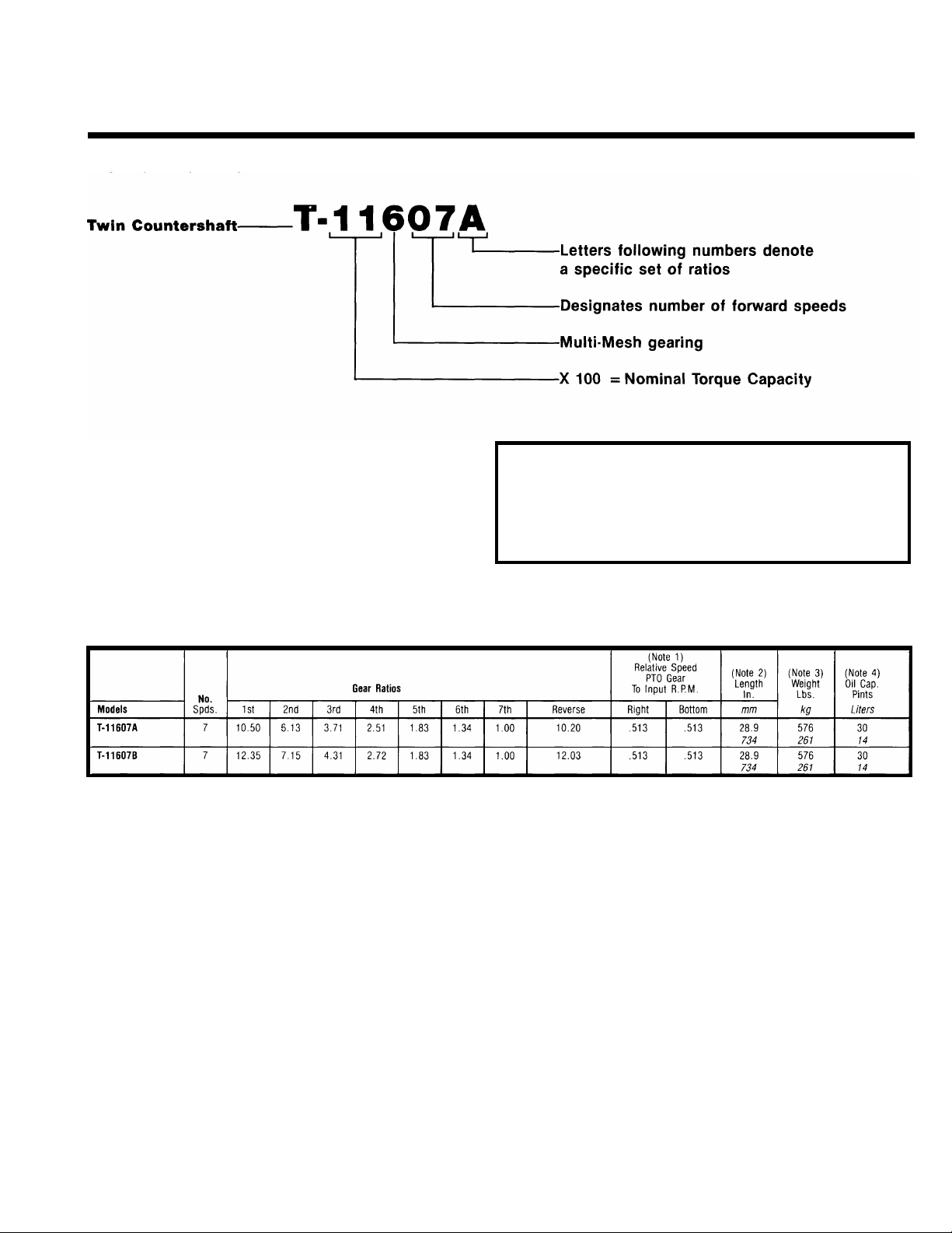
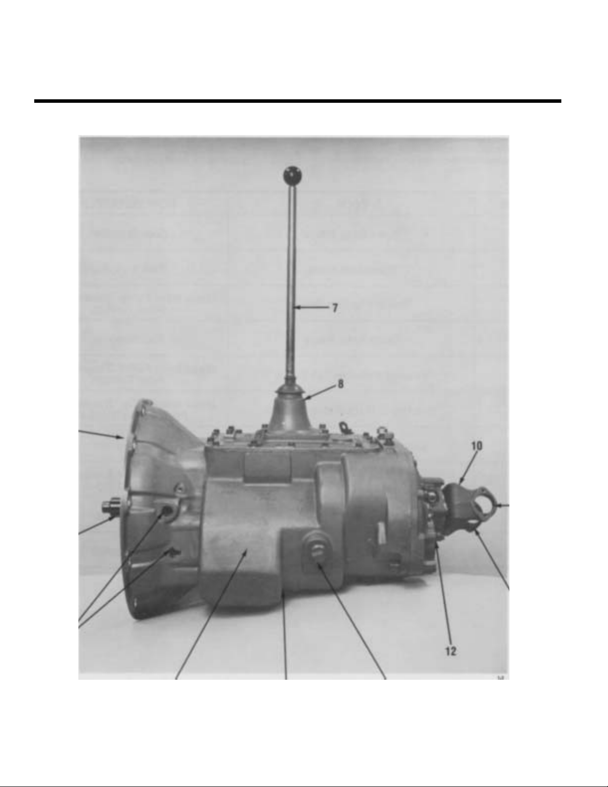
MODEL DESIGNATIONS
AND SPECIFICATIONS
Nomenclature:
IMPORTANT: All Fuller Transmissions are identified by model and serial number. This information
is stamped on the transmission identification tag
and affixed to the case.
DO NOT REMOVE OR DESTROY THE TRANSMISSION IDENTIFICATION TAG.
7 Speed Series Transmissions
See Chart Notes.
CHART NOTES:
1
Lengths measured from face of clutch housing to front bottoming surface of companion flange or yoke.
2
Weights include SAE No. 1 cast iron clutch housing and standard controls (gear shift lever and housing
assembly), less clutch release parts. For information on available clutch housings, refer to Publication
FUL-140 - ”Clutch Housing Chart.” All weights are approximate.
3
Oil Capacities are approximate, depending on inclination of engine and transmission. Always fill transmission with proper grade and type of lubricant to level of filler opening. See LUBRICATION.
Page 7
LUBRICATION
Proper
Lubrication...
the Key to long
transmission life
Proper lubrication procedures are the key to a
good all-around maintenance program. If the
oil is not doing its job, or if the oil level is
ignored, all the maintenance procedures in the
world are not going to keep the transmission
running or assure long transmission life.
so that the internal parts operate in a bath of
oil circulated by the motion of gears and shafts.
these procedures are closely followed:
Eaton
First 3,000 to 5,000 miles
(4827 to 8045 Km)
Every 10,000 miles
(16090 Km)
Every 250,000 miles
(402336 Km)
Every 100,000 miles (160,000 Km)
or every 3 years whichever occurs first fluid.
I
First 30 hours Factory fill Initial drain,
Every 40 hours Inspect fluid level Check for leaks
Every 500 hours Change transmission fluid where
I
Every 1,000 hours
I
I
First 3,000 to 5,000 miles Factory fill
(4827 to 8045 Km)
I
Every 10,000 miles
(16090 Km)
I
Every 50,000 miles
(80450 Km)
I
I
First 30 hours Change transmission lubricant on new units
Every 40 hours
Every 500 hours Change transmission Iubricant where
Every 1,000 hours Change transmission Iubricant
Change the oil filter when fluid or lubricant is changed.
®
Eaton
Fuller®Transmissions are designed
Thus, ail parts will be amply lubricated if
1. Maintain oil level. Inspect regularly.
2. Change oil regularly.
3. Use the correct grade and type of oil.
4. Buy from a reputable dealer.
Lubrication Change and Inspection
®
Roadranger®CD50 Transmission Fluid
HIGHWAY USE—Heavy Duty and Mid-Range
Factory fill
Inltlal drain
Check fluid level
Check for leaks
Heavy Duty Highway Change Interval
Change transmission
Mid-Range Highway Change Interval
Change transmission
OFF-HIGHWAY USE
severe dirt conditions exist.
Change transmission fluid
(Normal off-highway use),
Heavy Duty Engine Lubricant or
Mineral Gear Lubricant
HIGHWAY USE
Initial drain.
Inspect Iubricant level,
Check for leaks,
Change transmission
OFF-HIGHWAY USE
Inspect Iubricant level Check for leaks
severe dirt conditions exist.
(Normal off-highway use),
lubricant,
fluid,
Recommended Lubricants
Fahrenheit
(Celsius)
Ambient
Temperature
All
Above 10oF(-12oC.)
Above 10oF(-12oC.)
Below 10oF(-12oC.)
Above 10oF(-12oC.)
Below 10oF(-12oC.)
®
Grade
(SAE)
50
50
40
90
80W
Type
Eaton®Roadranger
CD50 Transmission
Fluid
Heavy Duty Engine 011
MI L-L-2104B C or D or
API-SF or API-CD
(Previous API designations 30
acceptable)
Mineral Gear 011 with rust
and oxidation Inhibitor
API-GL-1
The use of mild EP gear oil or multi-purpose gear oil is not recommended, but if
these gear oils are used, be sure to adhere to
the following limitations:
Do not use mild EP gear oil or multi-purpose gear oil when operating temperatures are
above 230°F (110
o
C). Many of these gear oils,
particularly 85W140, break down above 230°F
and coat seals, bearings and gears with deposits that may cause premature failures. If
these deposits are observed (especially a coating on seal areas causing oil leakage), change
to Eaton Roadranger CD50 transmission fluid,
heavy duty engine oil or mineral gear oil to
assure maximum component life and to maintain your warranty with Eaton. (Also see
“Operating Temperatures”.)
Additives and friction modifiers are not recom-
mended for use in Eaton Fuller transmissions.
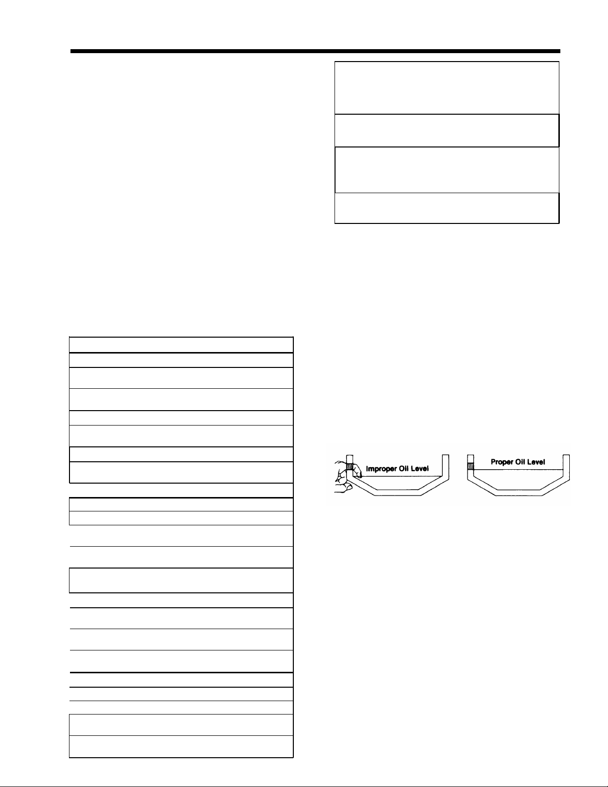
Proper Oil Level
Make sure oil is level with filler opening. Because you can reach oil with your finger does
not mean oil is at proper level. One inch of oil
level is about one gallon of oil.
Draining Oil
Drain transmission while oil is warm. To drain
oil remove the drain plug at bottom of case.
Clean the drain plug before re-installing.
Refilling
Clean case around filler plug and remove plug
from side of case. Fill transmission to the
level of the filler opening. If transmission has
two filler openings, fill to level of both openings.
The exact amount of oil will depend on the
transmission inclination and model. Do not
over fill—this will cause oil to be forced out
of the transmission.
When adding oil, types and brands of oil
should not be mixed because of possible incompatibility.
4
.
....
,.
Page 8
LUBRICATION
Operating Temperatures
—With Eaton
®
Roadranger
®
CD50 Transmission Fluid
Heavy Duty Engine Oil
and Mineral Oil
The transmission should not be operated consistently at temperatures above 250
However, intermittent operating temperatures
o
to 300
F (149oC) will not harm the transmission. Operating temperatures above 250
increase the lubricant’s rate of oxidation and
shorten its effective life. When the average
operating temperature is above 250
transmission may require more frequent oil
changes or external cooling.
The following conditions in any combina-
tion can cause operating temperatures of over
o
F: (1) operating consistently at slow
250
speeds, (2) high ambient temperatures, (3) restricted air flow around transmission, (4) exhaust system too close to transmission, (5)
high horsepower, overdrive operation.
External oil coolers are available to reduce
operating temperatures when the above conditions are encountered.
o
F (120oC).
o
F
o
F, the
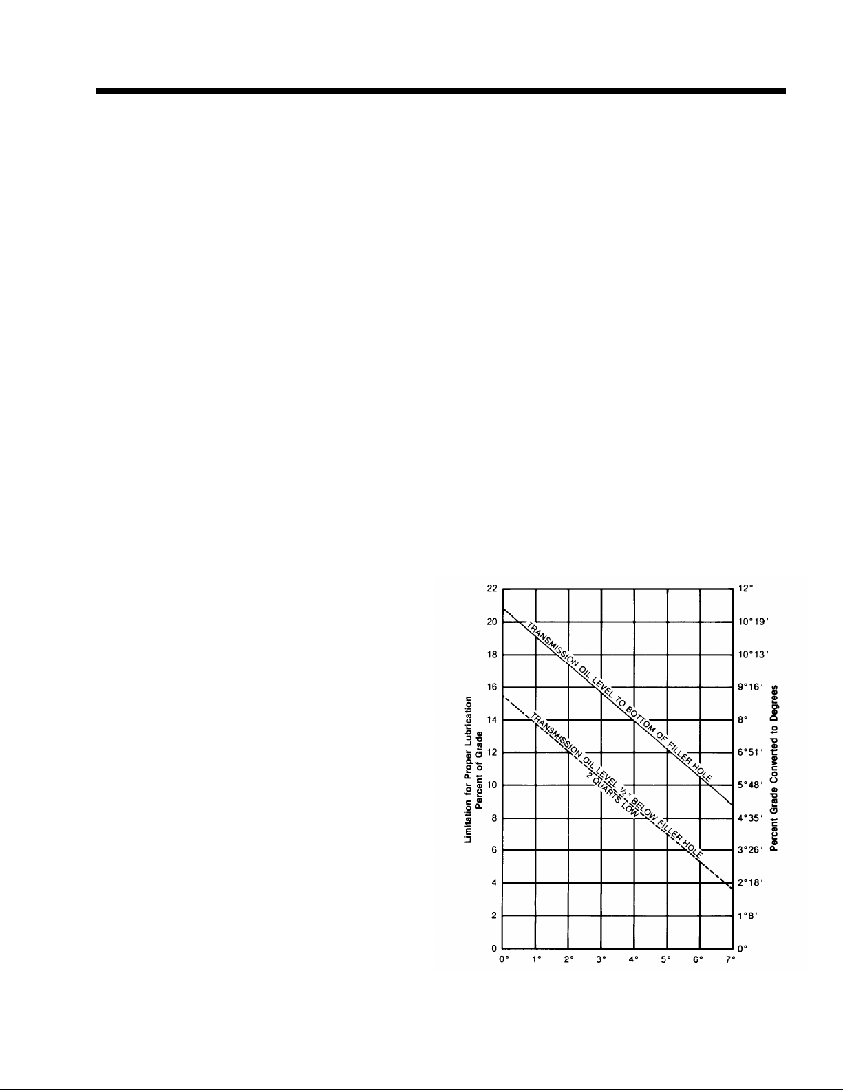
Proper Lubrication Levels
as Related to Transmission
Installation Angles
If the transmission operating angle is more
than 12 degrees, improper lubrication can occur. The operating angle is the transmission
mounting angle in the chassis plus the percent of upgrade (expressed in degrees).
The chart below illustrates the safe percent
of upgrade on which the transmission can be
used with various chassis mounting angles.
For example: if you have a 4 degree transmission mounting angle, then 8 degrees (or 14
percent of grade) is equal to the limit of 12
degrees. If you have a O degree mounting
angle, the transmission can be operated on a
12 degree (21 percent) grade.
Anytime the transmission operating angle of
12 degrees is exceeded for an extended
period of time the transmission should be
equipped with an oil pump or cooler kit to
insure proper lubrication.
Note on the chart the effect low oil levels
can have on safe operating angles. Allowing
the oil level to fall 1/2” below the filler plug
hole reduces the degree of grade by approximately 3 degrees (5.5 percent).
Proper Lubrication Levels are Essential!
Transmission Oil Coolers are:
Recommended
— With engines of 350 H.P. and above
with overdrive transmissions
Required
— With engines 399 H.P. and above with
overdrive transmissions and GCW’S
over 90,000 lbs.
— With engines 399 H.P. and above and
1400 Lbs.-Ft. or greater torque
— With engines 450 H.P. and above
— With EP or Multipurpose Gear Oil
Mild EP gear oil and multipurpose gear oil are
not recommended when lubricant operating
temperatures are above 230°F (110). In addition, transmission oil coolers are not recom-
mended with these gear oils since the oil
cooler materials may be attacked by these
gear oils. The lower temperature limit and oil
cooler restriction with these gear oils generally limit their success to milder applications.
Transmission Mounting Angle
Dotted line showing “2 Quarts Low” is for
reference only. Not recommended.
Page 9
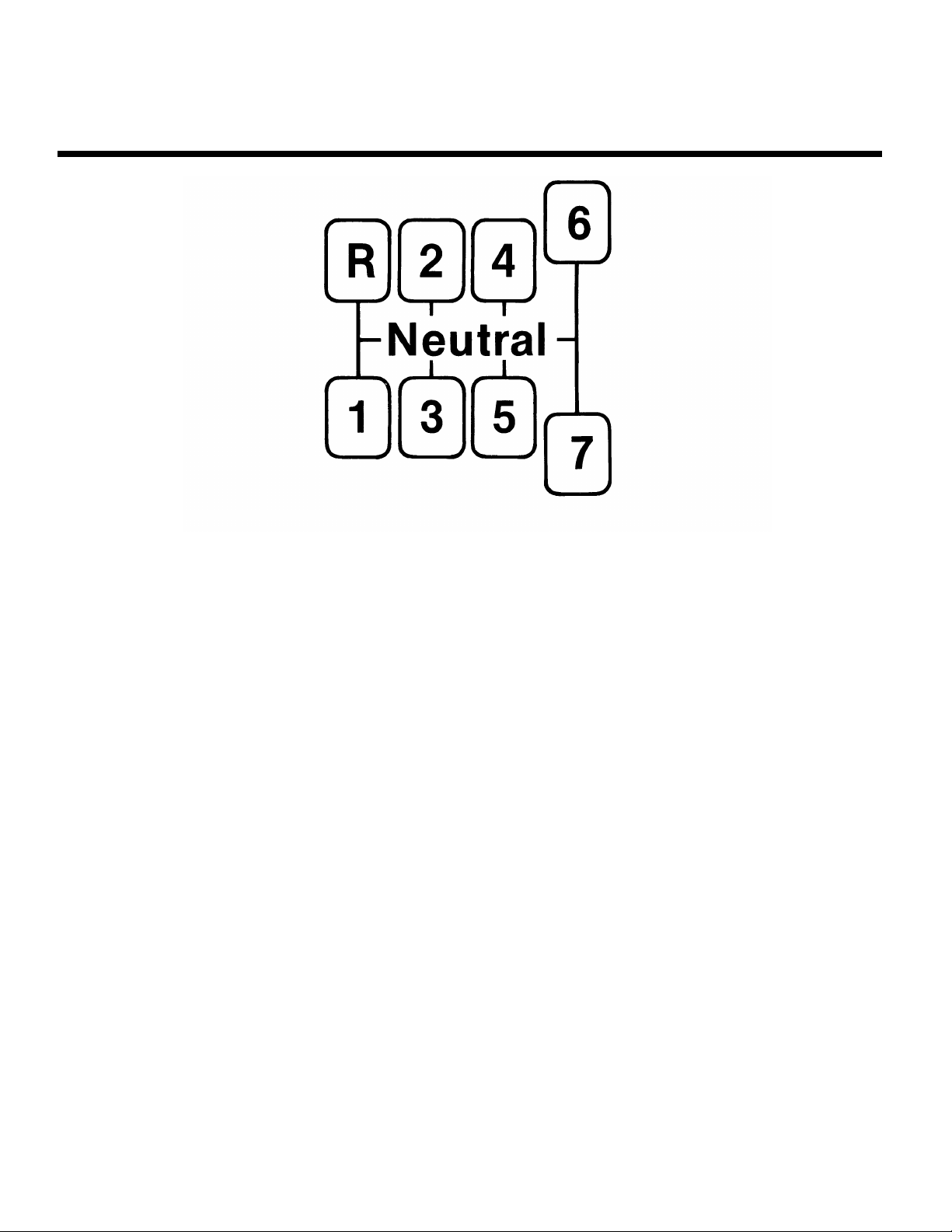
OPERATION
Shift Lever Patterns
The T-11607 transmissions have seven forward
speeds and one reverse. All models are shifted as
you would shift any non-synchronized manual trans-
mission, following the simple 7-speed shift pattern.
Always double-clutch when making lever shifts.
The longer lever throw in 6th and 7th gear posi-
tions provide greater clutching tooth contact.
Page 10

POWER FLOW
The transmission must transfer the engine's power in terms of torque to the vehicle's rear wheels. Knowledge
of what takes place in the transmission during torque transfer is essential when trouble-shooting and making
repairs become necessary.
1.
Torque from the engine is transferred to the
transmission's input shaft.
2.
Splines of input shaft engage internal splines in
hub of main drive gear.
Torque is split between the two countershaft
3.
drive gears.
Torque is delivered along both countershaft to
4.
countershaft gears of "engaged" mainshaft gear.
The cross section view illustrates 1st speed gear
engagement.
Internal clutching teeth in hub of engaged main-
5.
shaft gear transfers torque to mainshaft through
sliding clutch.
Mainshaft transfers torque directly to output
6.
shaft.
1.
2.
3.
4.
5.
1st SPEED POWER FLOW
Page 11
TIMING
All Fuller Twin countershaft transmissions are “timed” at assembly. It is important that proper timing
procedures are followed when reassembling the
transmission. Timing assures that the countershaft
gears will contact the mating mainshaft gears at exactly the same time, allowing mainshaft gears to cen-
ter on the mainshaft and equally divide the load.
Timing is a simple procedure of making the appropriate teeth of a gear set prior to installation and
placing them in proper mesh while in the transmis-
sion.
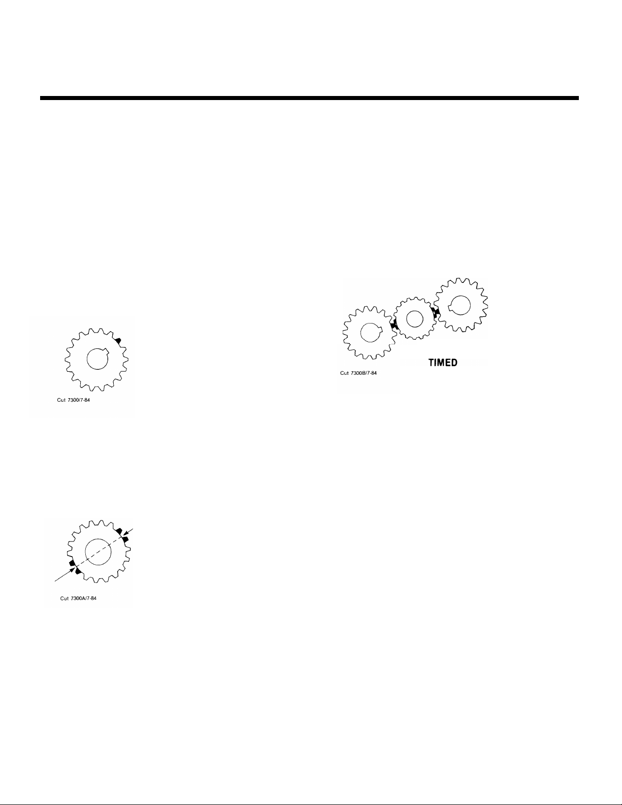
A. Marking Countershaft Drive Gear Teeth
1. Prior to placing each countershaft assembly
into case, mark the tooth located directly
over the keyway of drive gear as shown. This
tooth is stamped with an “O” to aid identification.
A. TOOTH MARKED ON EACH
COUNTERSHAFT DRIVE GEAR
FOR TIMING PURPOSES
C. Meshing Marked Countershaft Drive Gear Teeth
with Marked Main Drive Gear Teeth.
1. When installing the bearings on left countershaft, mesh the marked tooth of countershaft drive gear with either set or two
marked teeth on the main drive gear.
2. Repeat the procedure when installing the
bearings on right countershaft (after installing mainshaft assembly), using the remaining set of two marked teeth on the main
drive gear to time assembly.
C. DRIVE GEAR SET PROPERLY
B. Marking Main Drive Gear Teeth.
1. Mark any two adjacent teeth on the main
drive gear.
2. Mark the two adjacent teeth located directly
opposite the first set marked on the main
drive gear. As shown below, there should be
an equal number of unmarked gear teeth on
each side between the marked sets.
B. TEETH MARKED ON MAIN
DRIVE GEAR FOR TIMING
PURPOSES
Page 12

TORQUE RECOMMENDATIONS
Correct torque application is extremely important to assure long transmission life and dependable performance.
Over-tightening or under-tightening can result in a loose installation and, in many instances, eventually cause
damage to transmission gears, shafts, and/or bearings. Use a torque wrench whenever possible to attain recom-
mended lbs./ft. ratings. Do not torque capscrews dry.
Page 13

TORQUE RECOMMENDATIONS
Page 14

TOOL REFERENCE
Some repair procedures pictured in this manual show
the use of specialized tools. Their actual use
ommended as they make
faster, and prevent costly
But for the most part,
such as socket wrenches, screwdrivers, etc., and
other standard shop items such as a press, mauls and
soft bars are all that is needed to successfully disassemble and reassemble any Fuller Transmission.
PAGE
25
transmission repair easier, quired by the individual user. Detailed Fuller Transmisdamage to critical parts.
ordinary mechanic’s tools
TOOL HOW OBTAINED
Snap Ring Pliers
is rec-
3 9 Mainshaft Hook
20
49
Tension Spring Driver
Snap Ring Pliers
The specialized tools listed below can be obtained
from a tool supplier or made from dimensions as re-
sion Tool Prints are availabe upon request by writing.
Eaton Corporation
Transmission Division
Technical Service Dept.
P.O. Box 4013
Kalamazoo, Michigan 49003
Tool Supplier
Tool Supplier
Made from Fuller Transmission
Print T-11938
Tool Supplier
38
50
50
52
74
Torque Wrench, 1000 Lbs./Ft. Capacity
Bearing Puller w/Set Screw
Bearing Drivers (Flanged-End)
Countershaft Support Tool
Input Shaft Nut Installer
5 1 Input Shaft Bearing Driver
*Dimensions necessary to determine specific tool number required.
Made from Fuller Transmission
Print T-10325
Made from Fuller Transmission
Print Series T-10842*
Tool Supplier
Made from Fuller Transmission
Print T-22553-A
Tool Supplier
Tool Supplier
Page 15
PREVENTIVE MAINTENANCE
Page 16

PREVENTIVE MAINTENANCE
PREVENTIVE MAINTENANCE CHECK CHART
CHECKS WITHOUT PARTIAL
DISASSEMBLY OF CHASSIS OR CAB
1.
Clutch Housing Mounting
a. Check all capscrews in bolt circle of clutch
housing for looseness.
2.
Clutch Release Bearing (Not Shown)
Remove hand hole cover and check radial
a.
and axial clearance in release bearing.
b. Check relative position of thrust surface of
release bearing with thrust sleeve on pushtype clutches.
Clutch Pedal Shaft and Bores
3.
Pry upward on shafts to check wear.
a.
b. If excessive movement is found, remove
clutch release mechanism and check bushings in bores and wear on shafts.
Lubricant
4.
a.
Change at specified service intervals.
b. Use only the types and grades as recom-
mended. See LUBRICATION.
Filler and Drain Plugs
5.
Remove filler plugs and check level of lubri-
a.
cant at specified intervals. Tighten filler and
drain plugs securely.
Capscrews and Gaskets
6.
a. Check all capscrews, especially those on
PTO covers and rear bearing covers for
looseness which would cause oil leakage.
See TORQUE RECOMMENDATIONS.
b. Check PTO opening and rear bearing covers
for oil leakage due to faulty gasket.
Gear Shift Lever
7.
a. Check for looseness and free play in hous-
ing. If lever is loose in housing, proceed
with Check No. 9.
8. Gear Shift Lever Housing Assembly
Remove the gear shift lever housing as-
a.
sembly from transmission.
b. Check tension spring and washer for set
and wear.
c.
Check the gear shift lever spade pin and
spade in slot for wear.
d. Check bottom end of gear shift lever for
wear and check slot of yokes and blocks in
shift bar housing for wear at contact points
with shift lever.
CHECKS WITH DRIVE LINE DROPPED
9.
Universal Joint Companion Flange
or Yoke Nut
a. Check for tightness. Tighten to recom-
mended torque.
10. Output Shaft (Not Shown)
a.
Pry upward against output shaft to check
radial clearance in mainshaft rear bearing.
CHECKS WITH UNIVERSAL JOINT
COMPANION FLANGE OR YOKE
REMOVED
NOTE: If necessary, use solvent and shop rag to
clean sealing surface of companion flange or
yoke. DO NOT USE CROCUS CLOTH, EMERY
PAPER OR OTHER ABRASIVE MATERIALS
THAT WILL MAR SURFACE FINISH.
11.
Splines on Output Shaft
(Not Shown)
a. Check for wear from movement and chuck-
ing action of the universal joint companion
flange or yoke.
12.
Mainshaft Rear Bearing Cover
a.
Check oil seal for wear.
Page 17

PRECAUTIONS
Disassembly
It is assumed in the detailed disassembly instructions that the lubricant has been drained from transmission,
the necessary linkage and air lines disconnected and the transmission has been removed from vehicle chassis.
Removal of the gear shift lever housing assembly (or remote control assembly) is included in the detailed in-
structions (Disassembly and Reassembly—Shifting Controls); however, this assembly MUST be detached from
shift bar housing before transmission can be removed.
FOLLOW CLOSELY EACH PROCEDURE IN THE DETAILED INSTRUCTIONS. MAKING USE OF THE TEXT. ILLUSTRATIONS AND PHOTOGRAPHS PROVIDED.
1
BEARINGS — Carefully wash and relubricate all
reusable bearings as removed and protectively
wrap until ready for use. Remove bearings planned
to be reused with pullers designed for this pur-
pose.
2. ASSEMBLIES — When disassembling the various
assemblies, such as the mainshaft, countershaft,
and shift bar housing, lay all parts on a clean
bench in the same sequence as removed. This procedure will simplify reassembly and reduce the
possibility of losing parts.
3. SNAP RINGS — Remove snap rings with Pliers de-
signed for this purpose. Snap rings removed in this
manner can be reused, if they are not sprung or
loose.
4
INPUT SHAFT — The input shaft can be removed
from transmission without removing the coun-
tershafts, mainshaft, or main drive gear. Special
procedures are required and provided in this manual.
5.
CLEANLINESS — Provide a clean place to work. It
is important that no dirt or foreign material enters
the unit during repairs, Dirt is an abrasive and can
damage bearings. It is always good practice to
clean the outside of the unit before starting the
planned disassembly.
6. WHEN USING TOOLS TO MOVE PARTS — Always
apply force to shafts, housings, etc, with restraint.
Movement of some parts is restricted. Never apply
force to the part being driven after it stops solidly.
The use of soft hammers, bars and mauls for all
disassembly work is recommended.
Inspection
Before reassembling the transmission, check each part carefully for abnormal or excessive wear and damage to
determine reuse or replacement. When replacement is necessary, use only genuine Fuller Transmission parts to
assure continued performance and extended life from your unit.
Since the cost of a new part is generally a small fraction of the total cost of downtime and labor, avoid reusing a questionable part which could lead to additional repairs and expense soon after initial reassembly. To aid
in determining the reuse or replacement of any transmission part, consideration should also be given to the
unit’s history, mileage, application, etc.
Recommended inspection procedures are provided in the following checklist.
A. BEARINGS
1.
Wash all bearings in clean solvent. Check
balls, rollers and raceways for pitting, discoloration, and spalled areas. Replace bearings
that are pitted, discolored, or spalled.
2.
Lubricate bearings that are not pitted, discolored, or spalled and check for axial and radial
clearances.
3.
Replace bearings with excessive clearances.
4.
Check bearing fits. Bearing inner races
should be tight to shaft; outer races slightly
tight to slightly loose in case bore. If bearing
spins freely in bore, however, case should be
replaced.
B. GEARS
1. Check gear teeth for frosting and pitting.
Frosting of gear tooth faces present no threat
of transmission failure. Often in continued
operation of the unit, frosted gears will “heal”
and not progress to the pitting stage. And in
most cases, gears with light to moderate pitted teeth have considerable gear life remain-
ing and can be reused. But gears with
advanced stage pitting should be replaced.
2. Check for gears with clutching teeth abnormally worn, tapered, or reduced in length
from clashing in shifting. Replace gears
found in any of these conditions.
Page 18

PRECAUTIONS
Inspection (cont’d.)
3. Check axial clearance of gears. Where excessive clearance is found, check gear snap ring,
washer, spacer, and gear hub for excessive
wear. Maintain .005” to .012” axial clearance
between mainshaft gears.
C. SPLINES
1. Check splines on all shafts for abnormal wear.
If sliding clutch gears, companion flange, or
clutch hub have worn into the sides of the
splines, replace the specific shaft affected.
D. TOLERANCE/LIMIT WASHERS
1. Check surfaces of all limit washers. Washers
scored or reduced in thickness should be
replaced.
E. REVERSE IDLER GEAR ASSEMBLIES
1. Check for excessive wear from action of roller
bearings.
F. GRAY IRON PARTS
1. Check all gray iron parts for cracks and breaks.
Replace or repair parts found to be damaged.
Heavy castings may be welded or brazed provided the cracks do not extend into bearing
bores or bolting surfaces. When welding, however, never place the ground so as to allow current to pass through the transmission.
G. CLUTCH RELEASE PARTS
Check clutch release parts. Replace yokes
1.
worn at cam surfaces and bearing carrier
worn at contact pads.
2. Check pedal shafts. Replace those worn at
bearing surfaces.
I.
GEAR SHIFT LEVER HOUSING
ASSEMBLY
1. Check spring tension on shift lever. Replace
tension spring and washer if lever moves too
freely.
2. If housing is disassembled, check spade pin
and corresponding slot in lever for wear. Re-
place both parts if excessively worn.
BEARING COVERS
J.
1. Check covers for wear from thrust of adjacent
bearing. Replace covers damaged from thrust
of bearing outer race.
2. Check bores of covers for wear. Replace
those worn oversize.
K.
OIL RETURN THREADS
AND SEALS
1.
Check oil return threads in front bearing
cover. If sealing action of threads has been
destroyed by contact with input shaft, replace
bearing cover.
2.
Check oil seal in mainshaft rear bearing cover.
If sealing action of lip has been destroyed, re-
place seal.
L.
SLIDING CLUTCHES
1. Check all shift yokes and yoke slots in sliding
clutches for extreme wear or discoloration
from heat.
2. Check engaging teeth of sliding clutches for
partial engagement pattern.
H. SHIFT BAR HOUSING ASSEMBLY
1. Check for wear on shift yokes and blocks at
pads and lever slot. Replace excessively worn
parts.
2. Check yokes for correct alignment. Replace
sprung yokes.
3. Check Iockscrews in yokes and blocks.
Tighten and rewire those found loose.
4. If housing has been disassembled, check
neutral notches of shift bars for wear from interlock balls.
Page 19

PRECAUTIONS
Reassembly
Make sure that interiors of case and housings are clean. It is important that dirt and other foreign materials be
kept out of the transmission during reassembly. Dirt is an abrasive and can damage polished surfaces of
bearings and washers. Use certain precautions, as listed below, during reassembly,
AXIAL CLEARANCES - Maintain original axial
1.
GASKETS - Use new gaskets throughout the
transmission as it is being rebuilt. Make sure all
gaskets are installed. An omission of any gasket
can result in oil leakage or misalignment of
bearing covers.
2.
CAPSCREWS - To prevent oil leakage, use Loctite
242 thread sealant on all capscrews. For torque
ratings, see TORQUE RECOMMENDATIONS.
3.
O-RINGS - Lubricate all O-rings with silicon lubri-
cant.
4.
ASSEMBLY - Refer to the illustrations provided in
the detailed disassembly instructions as a guide
to reassembly.
5.
INITIAL LUBRICATION - Coat all limit washers
and splines of shafts with Lubriplate during reassembly to prevent scoring and galling of such
parts.
6.
clearances of .005” to .012” for mainshaft gears.
BEARINGS - Use of flanged-end bearing drivers is
7.
recommended for the installation of bearings.
These special drivers apply equal force to both
bearing races, preventing damage to balls/rollers
and races while maintaining correct bearing alignment with bore and shaft. Avoid using a tubular or
sleeve-type driver, whenever possible, as force is
applied to only one of the bearing races. See
TOOL REFERENCE.
UNIVERSAL JOINT COMPANION FLANGE OR
8.
YOKE - Pull the companion flange or yoke tightly
into place with the output shaft nut, using 450-500
foot-pounds of torque. Make sure the speedometer drive gear or a replacement spacer of the same
width has been installed. Failure to pull the com-
panion flange or yoke tightly into place will permit
the output shaft to move axially with resultant
damage to the rear bearing.
IMPORTANT: REFER TO THE APPROPRIATE ILLUSTRATED PARTS LIST (SPECI-
FIED BY MODEL SERIES) TO ENSURE THAT PROPER PARTS ARE
USED DURING REASSEMBLY OF THE TRANSMISSION.
Page 20

CHANGING INPUT SHAFT
Special Procedure
In some cases, it may become necessary to remove only the input shaft due to clutch wear on the splines. In
these cases the input shaft can be removed without disassembling the transmission other than removing the
shift bar housing. Removal of the clutch housing is optional.
Disassembly Reassembly
1.
Remove the gear shift lever housing and shift bar 1.
housing.
2.
Remove the front bearing cover capscrews.
3.
Engage two of the mainshaft sliding clutches so
that the mainshaft is locked up.
4.
Use paint to mark one tooth on each side of the
drive gear where it meshes with the countershaft
gears. Mark the countershaft tooth on each side of
the marked drive gear tooth. It is advisable to use
different colored paint on each countershaft to
avoid the possibility of re-installing the drive gear
incorrectly.
Drive against the back face of the drive gear to
5.
move the assembly forward and from the case
bore.
CAUTION:
DO NOT allow the mainshaft gearing to turn while
the drive gear is removed.
6. Proceed with normal disassembly of the drive gear
assembly.
Insert the reassembled drive gear assembly into
the case bore, returning the marked tooth on
each side of the drive gear to its original position
between the two marked teeth on each counter-
shaft. It may be necessary to lift the front of the
mainshaft slightly so that the mainshaft pilot enters the pocket in the input shaft. Drive against
the front of the input shaft to fully seat the
bearing in the case bore.
Re-install the front bearing cover, shift bar hous-
2.
ing and gear shift lever housing.
Page 21
DISASSEMBLY AND REASSEMBLY
SHIFTING CONTROLS
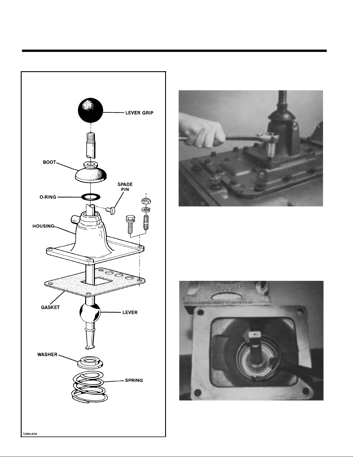
GEAR SHIFT LEVER HOUSING ASSEMBLY
A. Removal and Disassembly
1. Turn out retaining capscrews, jar lightly to break
gasket seal and remove gear shift lever housing
and gasket from shift bar housing.
NOTE: Remote control housings are removed
from shift bar housing in the same manner. For
disassembly and reassembly of LRC Assemblies,
see Illustrated Parts List No. P-541. For disassembly and reassembly of SRC Assemblies, see
Illustrated Parts List No. P-515.
2. Remove boot from gear shift lever and secure assembly in vise with bottom of housing up. Use a
large screwdriver to twist between the spring and
housing, forcing spring from under lugs in housing. Do one coil at a time.
Page 22

DISASSEMBLY AND REASSEMBLY
SHIFTING CONTROLS
B. Reassembly of Gear Shift Lever
3. Remove tension spring, washer and gear shift
lever from housing.
4. Remove spade pin from bore in housing tower. If
necessary, remove the O-ring from groove inside
tower.
1. With gear shift lever housing secured in vise as
during disassembly, install spade pin in bore of
housing tower. If previously removed, install Oring in tower groove.
2. Position the gear shift lever in housing with
spade pin in lever ball slot and install the tension
spring washer over ball, dished-side up.
Page 23
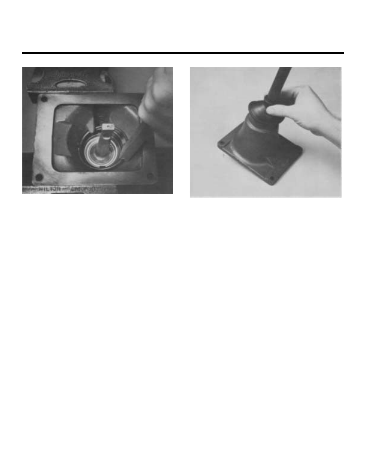
DISASSEMBLY AND REASSEMBLY
SHIFTING CONTROLS
3. Install tension spring under lugs in housing, seating one coil at a time. Use of a spring driving tool
is recommended.
4. Remove assembly from vise and install rubber
boot over gear shift lever and against housing.
Page 24

DISASSEMBLY AND REASSEMBLY
SHIFTING CONTROLS
SHIFT BAR HOUSING ASSEMBLY
Page 25

DISASSEMBLY AND REASSEMBLY
SHIFTING CONTROLS
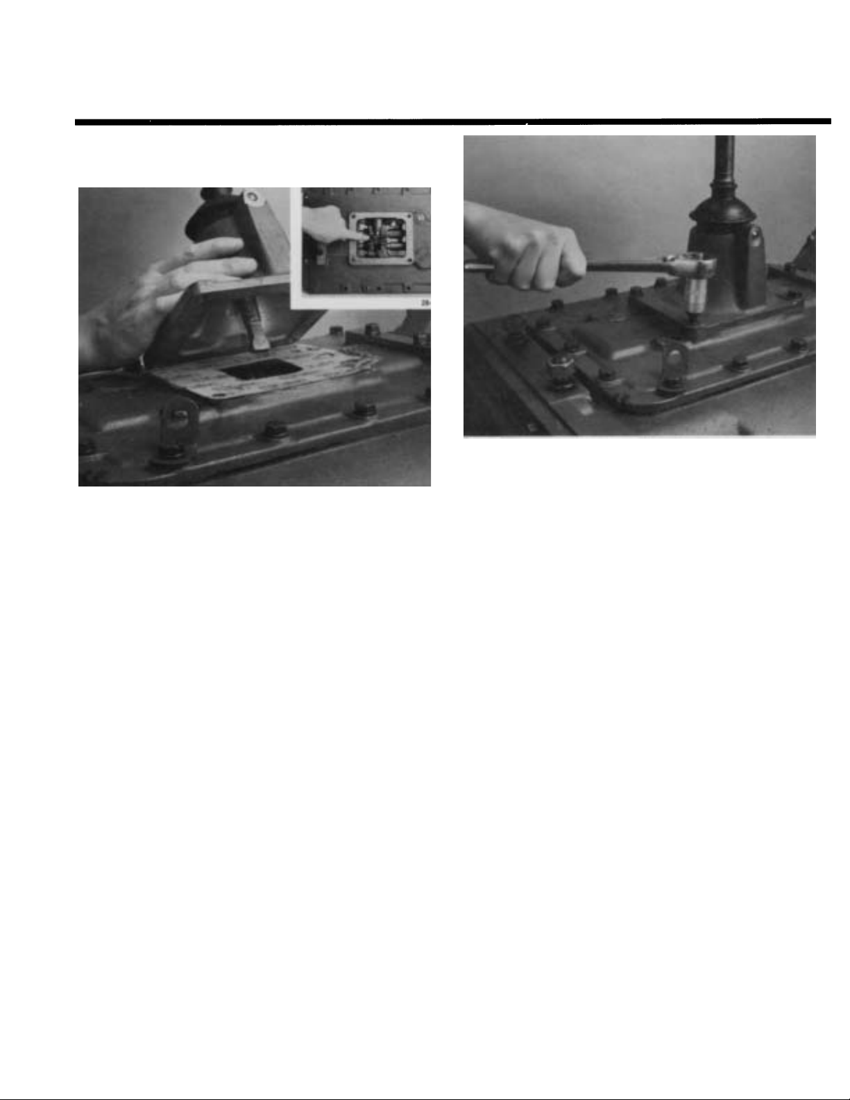
A. Removal and Disassembly
1. Turn out the retaining capscrews.
2. Turn out two capscrews and remove tension
spring cover.
3. Remove four tension springs.
4. Jar housing lightly to break gasket seal and lift
housing from transmission. Tip housing over to
remove four balls in tension spring bores (inset).
Page 26

DISASSEMBLY AND REASSEMBLY
SHIFTING CONTROLS
5. Cut lockwire and remove machined capscrew
from 1st and reverse shift block.
6. Mount housing in a vise as indicated using caution to avoid marring machined surface. Cut lockwire, turn out Iockscrews and remove direct yoke,
bar, and block from housing.
NOTE: When removing bars, remaining bars must
be kept in neutral position or interlock parts will
prevent removal.
7. Cut lockwire, turn out Iockscrew and remove the
4-5th speed yoke, bar, and spacer. As the bar is
pulled out of housing, remove interlock pin from
the bar (inset).
8.
Cut Iockwires, turn out Iockscrews and remove
2nd & 3rd speed yoke and block. Remove interlock pin from bar as it clears housing boss (inset).
Page 27

DISASSEMBLY AND REASSEMBLY
SHIFTING CONTROLS
9. Cut lockwires, turn out lockscrews and remove
the 1st-reverse finger, bar, and block from hous-
ing.
10. Remove three interlock balls from housing.
11. If necessary, remove snap ring, retainer, spring,
and plunger from 1st and reverse block (inset).
Use caution as the plug is spring loaded.
12. If necessary, turn out plug from 6th & 7th block
(inset). Remove spring and plunger.
Page 28

DISASSEMBLY AND REASSEMBLY
SHIFTING CONTROLS
B. Reassembly of Shift Bar
Housing Assembly
NOTE: When installing Iockscrews, make sure
that the end of the Iockscrew seats in the bore in
the bar. Torque Iockscrews to 35-45 lbs/ft. Excessive torque can result in distortion of the bars.
Use lockwire on all Iockscrews.
3. Secure housing in vise as shown. Install 1st-re-
verse finger, bar, and block.
1. If previously removed, install plunger and spring
in block (insert), and secure with plug. Apply
pressure against plug to compress spring fully.
Tighten plug and then back off 1/4 - 1/2 turns. Stake
the threads in hole on side of block.
4. Install capscrews and wire securely.
NOTE:
1st-reverse finger.
make sure the short capscrew is used in
2. If previously removed, install plunger, springs, retainer (inset), and snap ring, in direct block mak-
ing sure snap ring is seated in groove in block.
Page 29

DISASSEMBLY AND REASSEMBLY
SHIFTING CONTROLS
5. Install an interlock ball in housing bore against
the bar.
6. Install 2nd & 3rd speed block, and yoke on bar. install interlock pin in bar as it enters housing (inset).
7. Install an interlock ball in housing bore against
the bar.
8. Install 4th & 5th speed yoke, spacer, and bar. Install interlock pin in bar as it enters the housing
(inset).
Ñ
Page 30
DISASSEMBLY AND REASSEMBLY
SHIFTING CONTROLS
9. Install the remaining interlock ball in the housing
bore against the bar.
10. Install direct yoke, block and bar in housing. Torque capscrews and wire securely.
11. Install four balls in tension spring bores and install four tension springs (inset).
12.
Install gasket and tension spring cover.
Page 31

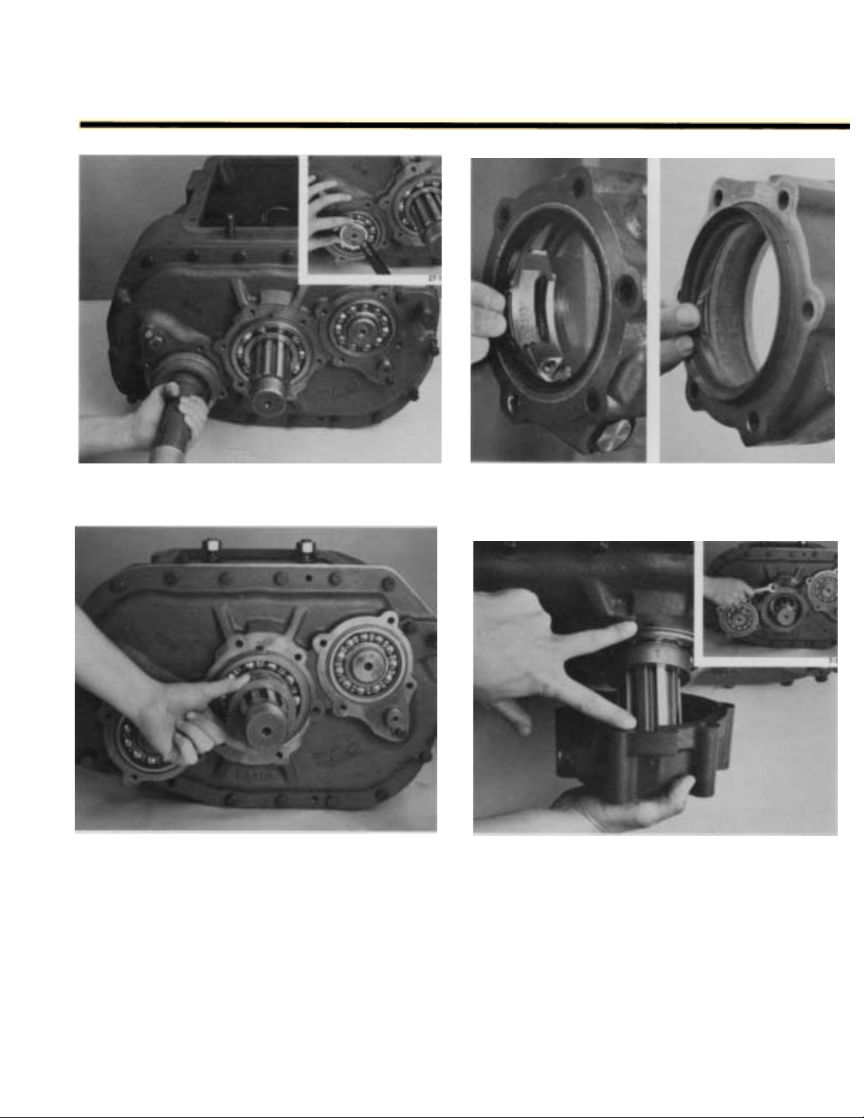
REMOVAL - COMPANION FLANGE AND
CLUTCH HOUSING
COMPANION FLANGE AND CLUTCH HOUSING
A. Removal of Companion Flange or Yoke
1. Lock the transmission by engaging two mainshaft gears with sliding clutches (inset). Use a
large braker bar to turn the nut from output shaft.
2. Pull yoke and speedo gear or spacer from output
shaft.
Page 32

REMOVAL - COMPANION FLANGE AND
CLUTCH HOUSING
B. Removal of Clutch Housing
1. For models so equipped, remove clutch release
mechanism and/or clutch brake assembly. See
OPTIONS.
2. Remove four capscrews and six nuts from studs
(left). Jar clutch housing with a rubber mallet to
break gasket seal and pull from transmission
case (right).
Page 33

REMOVAL AND DISASSEMBLY OF
REAR HOUSING
A. Removal of Rear Housing
1. Turn out capscrews and remove both countershaft rear bearing covers.
2. Turn out capscrews and remove output shaft rear
bearing cover. If necessary, remove the oil seal
from cover (inset).
Page 34
REMOVAL AND DISASSEMBLY OF
REAR HOUSING
3. Remove spacer from output shaft.
4. Turn out rear plate retaining capscrews.
5. Install three 4-inch capscrews in the three tapped
holes in rear plate and tighten evenly to move
plate to the rear. Remove capscrews.
Page 35

REMOVAL AND DISASSEMBLY OF
REAR HOUSING
B. Disassembly of Rear Housing
1. Position rear plate in vise as shown.
2. Use a soft bar to drive output shaft bearing from
bore.
Page 36

REMOVAL AND DISASSEMBLY OF
REAR HOUSING
3. Remove snap rings from rear countershafts.
4. Remove rear countershaft and bearings from
rear plate by driving shafts to the rear.
5. Block the countershaft bearings and press them
from shaft, remove inner snap ring (inset) if so
equipped.
6. Remove capscrews and retainer plates from idler
shafts.
Page 37

REMOVAL AND DISASSEMBLY OF
REAR HOUSING
7. Remove idler shafts and reverse idler gears from
rear housing.
8. If necessary, remove O-rings from idler shafts
(left) and two sets of roller bearings from idler
gears (right).
Page 38

DISASSEMBLY - FRONT SECTION
A. Mainshaft Removal
3. Cut lockwire, remove capscrew and 1st/reverse
block.
1. Remove spacer (left) and reverse gear from mainshaft (right).
Ñ
2. Remove washer from hub of reverse gear and
snap ring from reverse gear if necessary (inset).
4. Remove rear mainshaft key.
Page 39

DISASSEMBLY - FRONT SECTION
5. Turn tolerance washer to align splines and remove from mainshaft.
6. Remove shift fork, clutch, and shift bar. Cut lockwire and remove capscrew and shift fork if necessary (inset).
7. Rotate tolerance washer inside 1st speed gear
(inset), remove gear, washer, and spacer.
8. Remove 1st & 2nd gear spacer from mainshaft.
Page 40

DISASSEMBLY - FRONT SECTION
9. Using a small screwdriver, remove snap ring from
inside 2nd speed gear.
10.
Move 2nd speed gear forward engaging it into its
clutch and against 3rd speed gear. Remove external splined spacer (inset).
11. Cut lockwire, remove bearing retainer capscrews
and retainers from rear of countershaft.
12. From inside case, use a long punch and maul to
drive right countershaft rear bearing to the rear
and from case bore. Use caution to avoid marring
case bore.
NOTE: Remove procedures will damage bearing.
Removal should not be attempted unless replacement of bearing is planned.
Page 41

DISASSEMBLY - FRONT SECTION
13. Remove snap rings from the front of both countershaft.
14. With soft bar and maul drive right countershaft to
rear until front of countershaft is even with front
of bearing.
15. Drive against rear of right countershaft to move it
as far forward as possible. This will expose front
bearing snap ring (inset).
16. Use a bearing puller to remove front countershaft
bearing.
Page 42
DISASSEMBLY - FRONT SECTION
17. Turn out retaining capscrews, jar to break
gasket seal and remove front bearing cover.
18. From inside case, tap lightly against back face
of drive gear until input shaft assembly can be
pulled by hand from case (inset).
19. Block right countershaft against the wall of the
case (inset). Hold 2nd speed gear against 3rd
speed gear, using a mainshaft hook on front of
shaft. Tilt assembly up and lift it from case. Use
caution as 2nd speed gear is free to fall off main
shaft.
Page 43

DISASSEMBLY - FRONT SECTION
B. Mainshaft Disassembly
1. Remove 2nd speed gear from rear of mainshaft
and place mainshaft assembly in vise, pilot end
up. Use brass jaws or wood blocks in vise to protect mainshaft.
2. Remove 6th and 7th speed clutch from mainshaft.
Page 44

DISASSEMBLY - FRONT SECTION
3. Remove short key and rotate tolerance washer
with screwdriver to align splines with those of
mainshaft (inset).
4. Remove 6th speed gear, tolerance washer, and
spacer from mainshaft.
5. Remove 5th speed gear and spacer from mainshaft.
6. Remove 4th and 5th speed clutch from mainshaft.
Page 45

DISASSEMBLY - FRONT SECTION
7. Remove mainshaft assembly from vise. Reinstall
mainshaft in vise with pilot of mainshaft facing
down.
8. Remove key from rear of mainshaft, rotate tolerance washer and remove washer.
9. Remove 2nd and 3rd speed clutch from rear of
mainshaft.
10. Rotate 3rd speed gear tolerance washer with
small screwdriver (inset) and remove gear, spacer,
and tolerance washer.
Page 46
DISASSEMBLY - FRONT SECTION
11. Remove 4th speed gear and spacer from
mainshaft.
12. Rotate tolerance washer and remove from
mainshaft.
Page 47
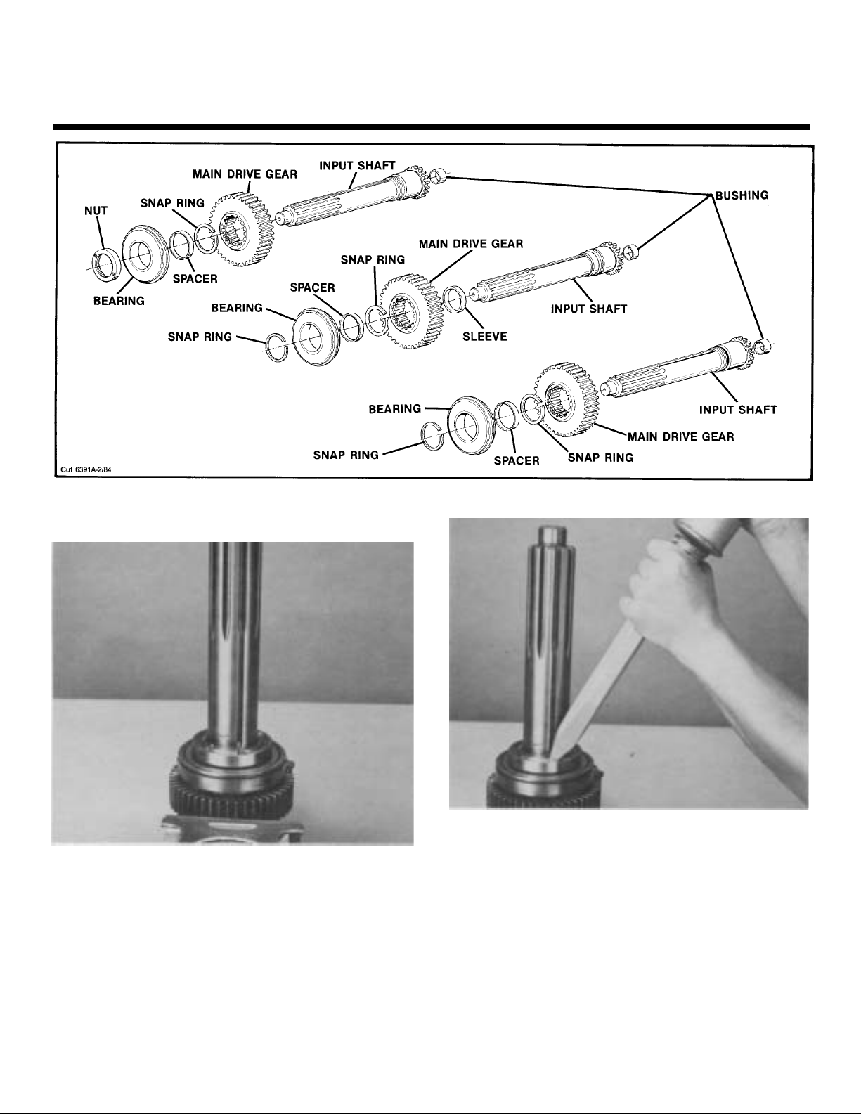
DISASSEMBLY - FRONT SECTION
C. Drive Gear Assembly-Disassembly
1. Mount assembly in a vise, pilot-end up, and recure on drive gear O.D. Vise used should be
equipped with brass jaws or wood blocks to prevent damage to the gear teeth.
2. Use a punch and maul to relieve drive gear
bearing nut from input shaft. For models
equipped with a snap ring to retain bearing, re-
move snap ring from groove of input shaft.
NOTE: A wear sleeve is pressed on input shaft of
models equipped with an oil seal in drive gear
bearing cover. DO NOT DAMAGE OR ATTEMPT
TO REMOVE WEAR SLEEVE FROM INPUT
SHAFT.
Page 48

DISASSEMBLY - FRONT SECTION
5. If necessary, remove snap ring from drive gear (inset). Check bushing in pocket of input shaft and
replace if worn or damaged.
3. Use a drive gear bearing nut remover to turn nut
from shaft, left-hand threads.
4. Remove assembly from vise. Using rear face of
drive gear as a base, press input shaft through
the bearing, spacer, and gear.
Page 49

DISASSEMBLY - FRONT SECTION
D. Countershaft Removal and Disassembly
NOTE: If not previously done, remove front and
rear bearings from lower countershaft using
same procedure as was used for upper countershaft bearing removal.
2.
Remove snap ring from front of countershaft.
1. Move upper countershaft to rear, move front of
shaft to center of case and remove through top of
case. Repeat same procedure to remove lower
countershaft assembly.
NOTE: Left and right countershaft assemblies are
identical. Disassembly if each is performed in the
same manner.
Page 50
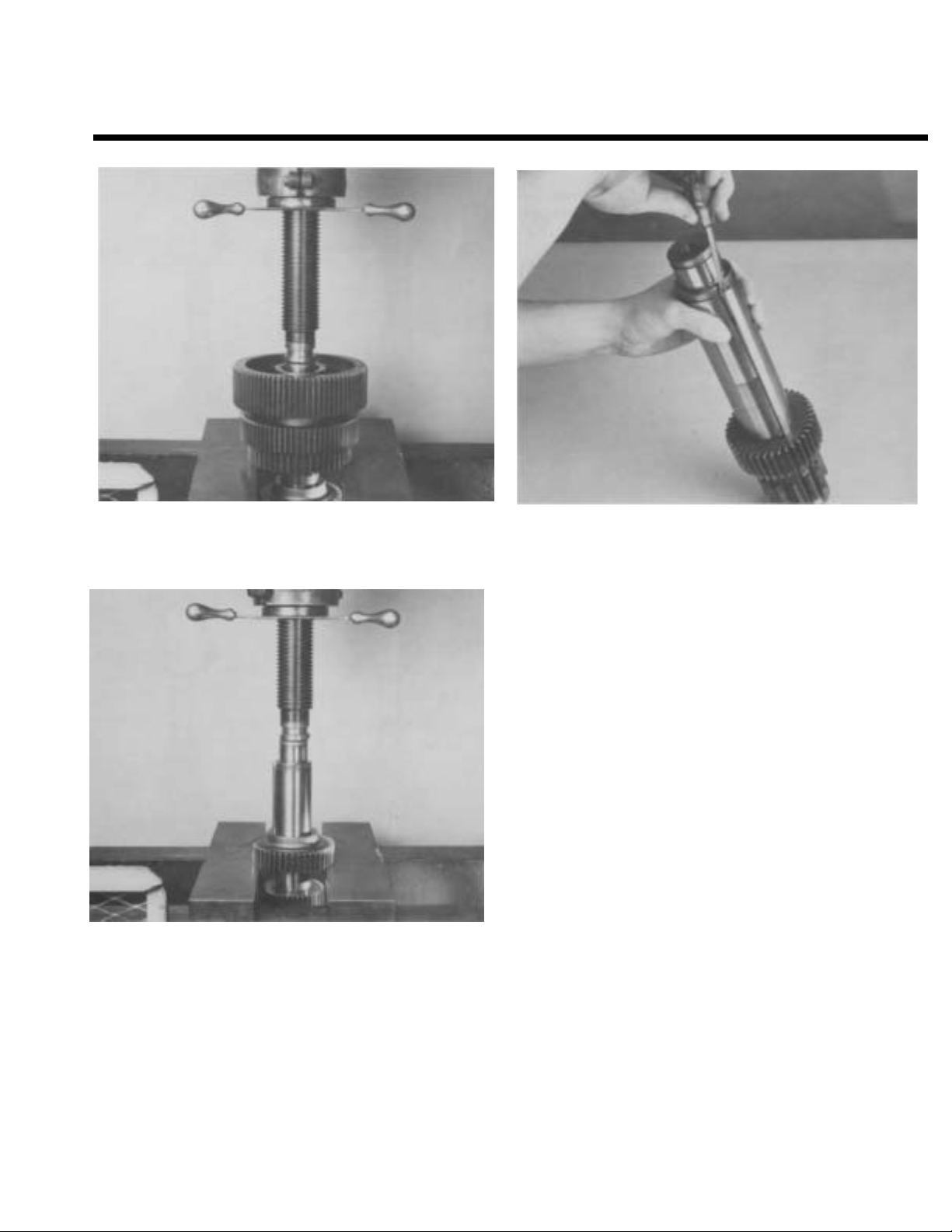
DISASSEMBLY - FRONT SECTION
3.
Press drive gear, 6th speed gear and 5th speed
gear from countershaft.
5. If necessary, remove key from countershaft.
4. Press 4th speed gear from countershaft.
Page 51

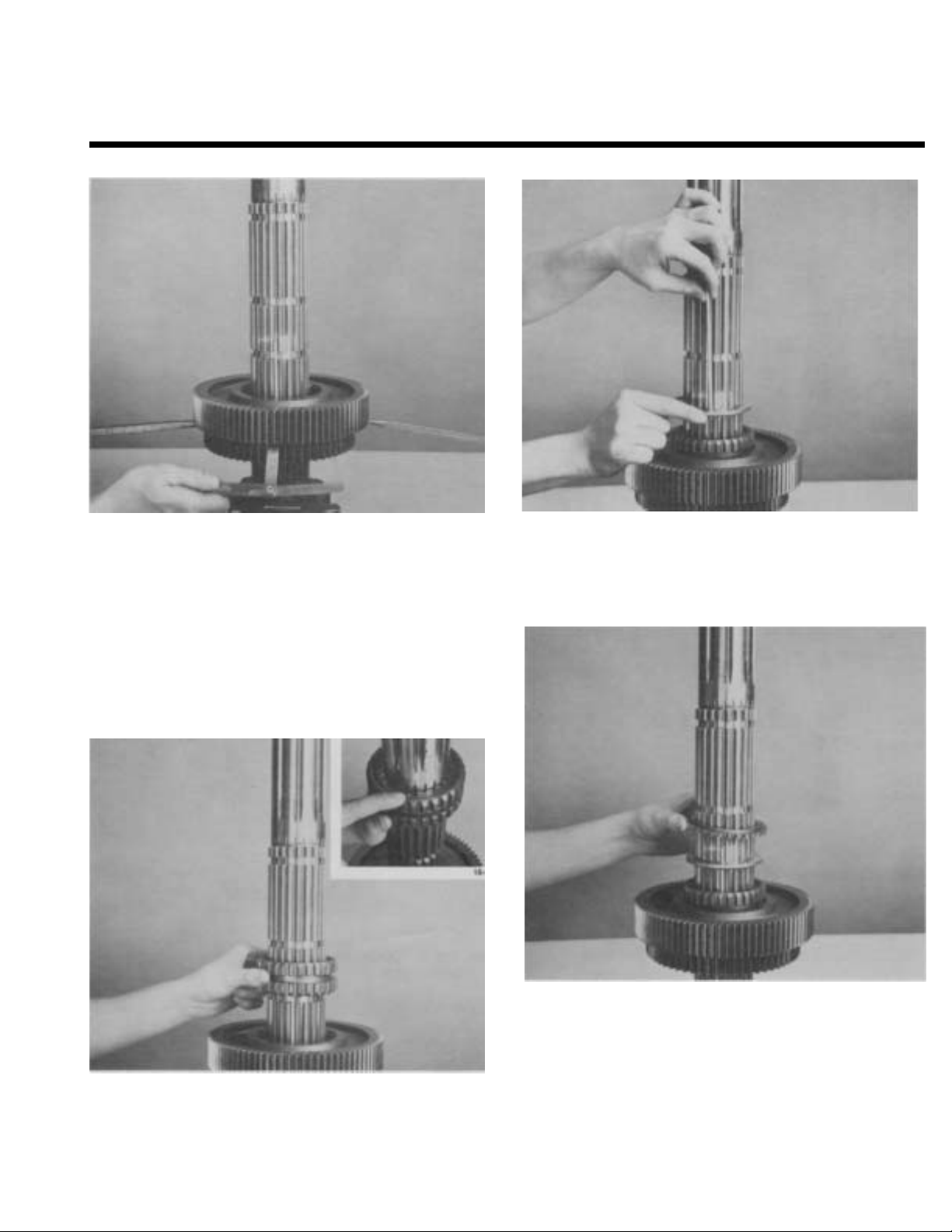
REASSEMBLY - FRONT SECTION
A. Countershaft Reassembly
NOTE: Since left and right countershaft assemblies are identical, reassembly of each is performed in the same manner.
3. Press the 5th speed gear on countershaft against
4th speed gear.
1. If previously removed, install key in keyway of
2. Align keyway of gear with key in countershaft and
press the 4th speed gear into position on shaft,
long hub of gear toward the front of countershaft.
4. Press the 6th speed gear on countershaft, long
hub of gear toward front of countershaft.
Page 52

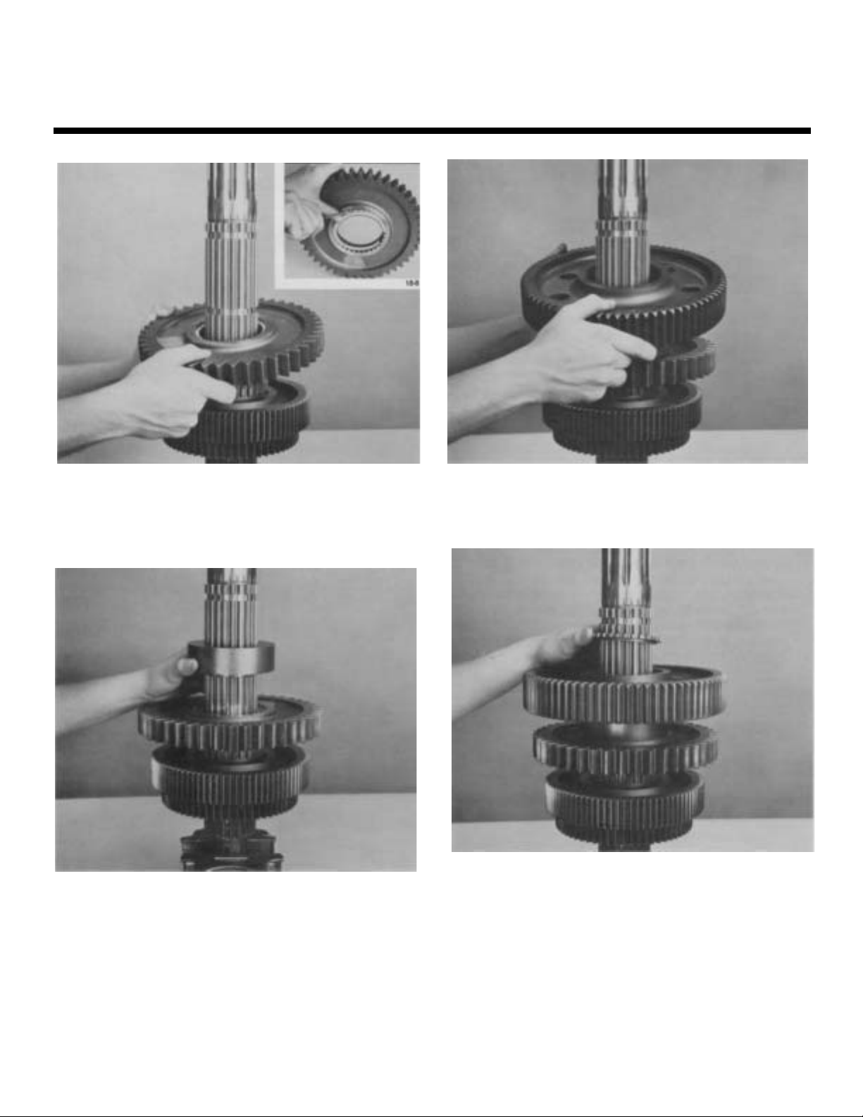
REASSEMBLY - FRONT SECTION
5. Press drive gear on countershaft, long hub of
gear toward 6th speed gear.
6. Install snap ring in groove nearest drive gear.
7. Mark countershaft drive gear for timing. On the
drive gear of each countershaft assembly, mark
Page 53

REASSEMBLY - FRONT SECTION
B. Countershaft Installation
3. Install rear countershaft capscrews and retainers
1. Install both countershaft assemblies back into
maincase.
NOTE: Both assemblies are identical.
and wire securely.
2. Use a centering tool in front bearing bore and install lower rear countershaft bearing with a
flanged bearing driver (inset).
4. Remove centering tool and install front countershaft bearing with a flanged bearing driver. Install
retaining snap ring (inset).
NOTE: Do not install upper countershaft bearings
at this time.
Page 54

REASSEMBLY - FRONT SECTION
C. Reassembly, Installation, and Timing
of Main Drive Gear Assembly
3.
Install drive gear spacer on input shaft and against
gear.
1. If previously removed, install snap ring in I.D. of
main drive gear and bushing in pocket of input
shaft (inset).
2. Install drive gear on input shaft, engaging internal
splines of gear with teeth on shaft, snap ring of
gear to front of shaft.
4. Press drive gear bearing on input shaft, bearing
shield to front of shaft, or use a flanged bearing
driver (inset).
Page 55

REASSEMBLY - FRONT SECTION
5. Apply Loctite grade 277 sealant to cleaned
threads of new drive gear bearing nut. DO NOT
REUSE OLD NUT.
NOTE: Models otherwise equipped with a snap
ring to retain bearing, install snap ring in groove
of input shaft and proceed to No. 8.
7. Use a punch and maul to peen nut into the two
milled slots of input shaft.
Mount assembly in a vise, pilot-end
6.
cure on drive gear O.D. Vise used should be
equipped with brass jaws or wood blocks to prevent damage to gear teeth. Clean threads of input
shaft and install drive gear bearing nut on shaft
(left). Using a drive gear bearing nut installer,
tighten nut on input shaft, lefthand threads, with
250-300 lbs./ft. of torque (right).
up, and se-
8. IMPORTANT: Remove assembly from vise to mark
main drive gear for timing purposes. Mark any
two adjacent teeth on drive gear and repeat procedure for the two adjacent teeth directly opposite first set marked. A highly visible color of
toolmakers' dye is recommended for making timing marks.
Page 56

REASSEMBLY - FRONT SECTION
9. Install main drive gear assembly approximately1/2
inch into maincase aligning either two marked
timing teeth of drive gear with marked tooth of
left countershaft (inset).
Page 57

REASSEMBLY—FRONT SECTION
SETTING CORRECT AXIAL
CLEARANCES FOR
MAINSHAFT GEARS
Axial Clearance (End-Play) Limits Are:
.005’’-,012” for all mainshaft gears
Washers are used to obtain the correct limits; six
thicknesses are available as follows:
LIMITS (INCH)
.248-.250
.253 -.255
.258-.260
.263-.265
.268-.270
.273 -.275
*
*NOTE: New style limit washers come in a full range
of tolerances as corresponding colors listed above
“plus red.” (Example: “Orange plus red” limit
washer has an inch limit thickness of .258 -.260.)
Refer to Illustrated Parts Lists for washer part numbers.
Always use the .248-.250” low limit washer (“White”
or “white plus red”) in the 4th and 2nd speed gear positions as shown at right.
COLOR CODE
WHITE
GREEN
ORANGE
PURPLE
YELLOW
BLACK
“PLUS RED”
Page 58

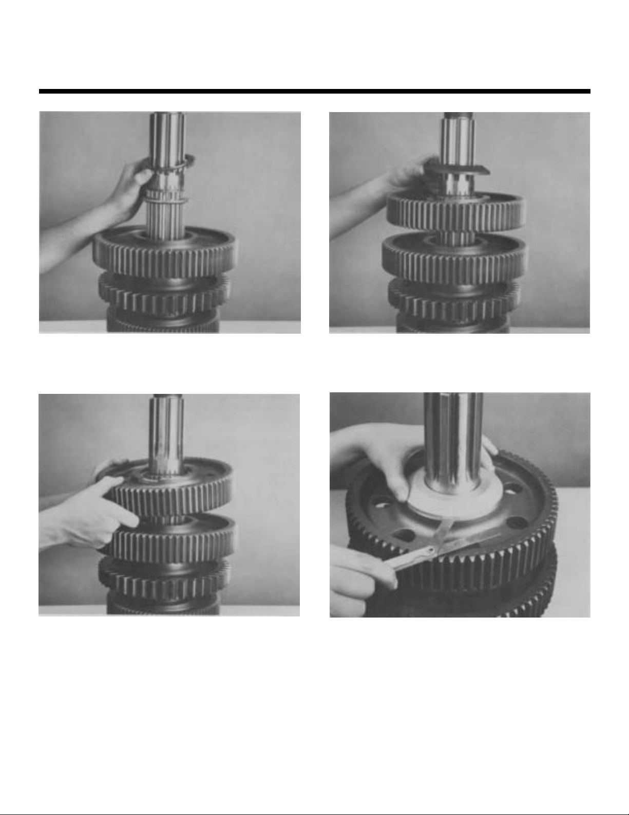
REASSEMBLY - FRONT SECTION
D. Mainshaft Reassembly and Installation
3. Install spacer, with shoulder of spacer facing up,
1. Install mainshaft in vise, front of shaft down. Use
brass jaws or wood blocks in vise to protect mainshaft. Make sure that roll pin is in place. If previously removed, install snap rings in hubs of
mainshaft gears.
against tolerance washer.
2. Install white color coded tolerance washer on mainshaft in 4th speed position, flat side of washer facing up. Rotate washer to align splines and install
key to lock washer in position.
NOTE: Key must be installed in keyway with roll
pin. Roll pin acts as forward slot) for key.
.
4. Install 4th speed gear on spacer with clutching
teeth facing down.
Page 59

REASSEMBLY - FRONT SECTION
5. install 3rd speed gear on 4th speed gear with
clutching teeth facing up.
6. Install spacer, shoulder facing down, into 3rd speed
gear.
7. Remove, key. Install tolerance washer with flat side
against spacer.
8. Rotate tolerance washer 1/2 spline and reinstall key
(inset).
Page 60
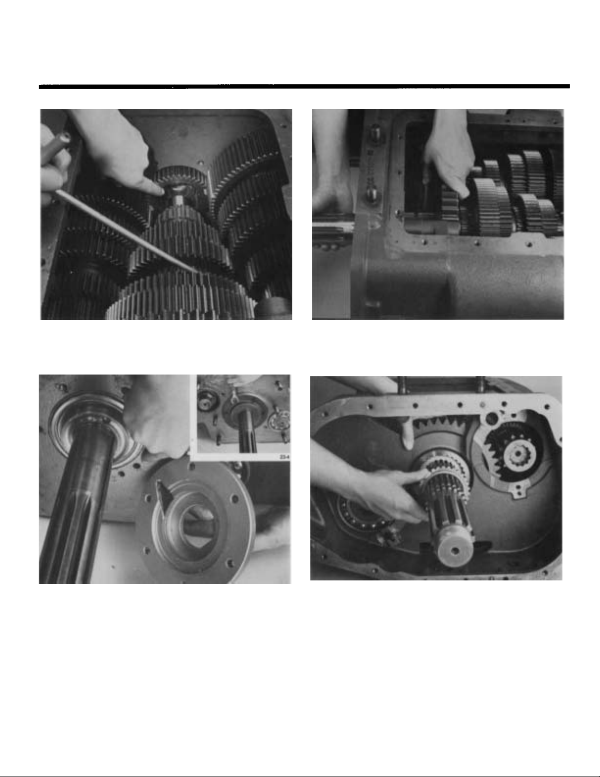
REASSEMBLY-FRONT SECTION
9. Insert two large screwdrivers between 3rd and 4th
speed gears. Apply slight downward pressure on
screwdriver handles to spread gears evenly. Making
certain gear hubs are parallel, insert feeler gage between gear hubs. Correct axial clearance is .005" to
.012". If clearance is less than the minimum .005"
tolerance, the tolerance washer in 3rd speed gear
should be replaced by a thinner washer. If clearance checked is larger than the maximum .012" tolerance, a thicker tolerance washer should be
installed in 3rd speed gear.
11. Remove key and install white color coded tolerance
washer in 2nd speed position with flat side of
washer facing up. Rotate washer 1/2 spline and reinstalI key.
10. Install 2nd and 3rd speed sliding clutch, aligning
missing internal spline of sliding clutch with key
(inset).
12. Install spacer with shoulder side up, against tolerante washer.
Page 61
REASSEMBLY-FRONT SECTION
13. Temporarily install snap ring in 2nd speed of gear
(inset). Install gear, clutching teeth facing down.
Engage clutching teeth of gear with external
splines of spacer.
14. Install spacer against back of 2nd speed gear.
15. Install 1st speed gear with clutching teeth facing
16. Install spacer, shoulder side facing down into 1st
speed gear.
Page 62

REASSEMBLY-FRONT SECTION
17. Install tolerance washer with flat side toward spacer.
18. Rotate washer 1/2 spline, and reinstall key (inset).
19.
Using two wood blocks and two large screwdrivers
to evenly spread 1st and 2nd speed gear check
clearance with feeler gage between spacer and 1st
speed gear. Correct clearance is .005" to .012". If it
is necessary to adjust clearance, change tolerance
washer in 1st gear.
20. Remove key and install white color coded tolerance
washer, flat side facing up, in reverse speed position. Reinstall key.
Page 63
REASSEMBLY - FRONT SECTION
21. Install spacer, shoulder side facing up, against tolerance washer.
Install reverse gear, clutching teeth facing down.
22.
Engage clutching teeth of gear with external
splines of spacer.
23. Install washer, with tapered side facing up, against
reverse gear.
24.
Apply downward pressure against spacer and
check clearance between spacer and reverse gear
with feeler gage. Correct clearance is .005" to
.012". If it is necessary to adjust clearance, change
tolerance washer in reverse gear.
Page 64

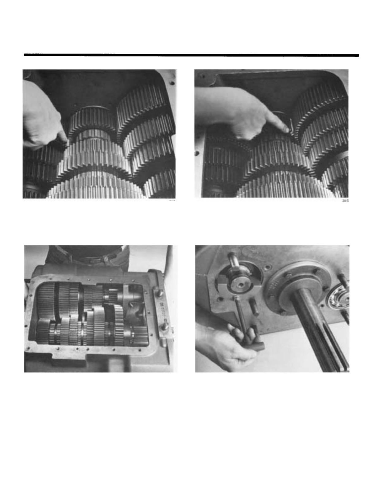
REASSEMBLY - FRONT SECTION
25. Remove spacer, reverse gear externally splined spacer, key, tolerance washer, 1st speed gear tolerance
washer, 1st speed gear spacer, 1st speed gear, 1st
and 2nd gear spacer, 2nd speed gear and its externally splined spacer from mainshaft. Keep re-
lated spacers and tolerance washers with gears. Do
not mix these parts after you have set axial clear-
ance between the gears.
27. Install 5th gear spacer, flat side facing up.
28. Install 5th speed gear with clutching teeth facing
down. Engage clutching teeth of gear with external
splines of spacer.
26. Remove mainshaft assembly from vise. Reinstall in
vise with front of mainshaft facing up. Install 4th5th speed sliding clutch, aligning missing internal
spline of sliding clutch with key in mainshaft.
Page 65

REASSEMBLY-FRONT SECTION
29. Install 6th speed gear with clutching teeth facing
up, against 5th speed gear.
30. Install spacer in 6th speed gear.
31. Install tolerance washer with flat side facing down,
against spacer. Rotate washer to align square notch
in washer with keyway in mainshaft and install
short key (inset).
32. Check clearance and make adjustments if necessary, between 5th and 6th speed gears. (In the same
manner as performed in step #9).
Page 66

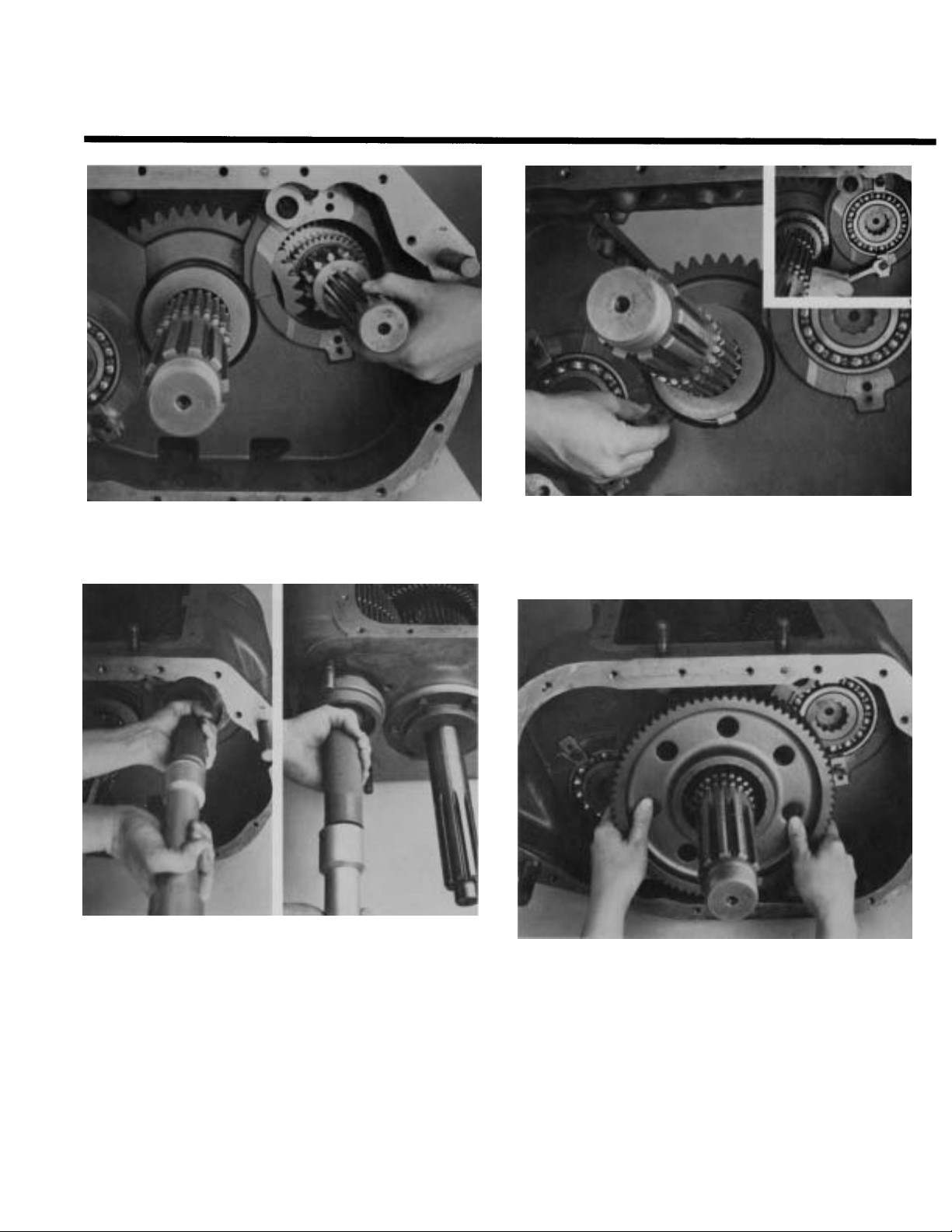
REASSEMBLY - FRONT SECTION
33. Install 6th and 7th speed sliding clutch, aligning
missing internal spline of clutch with key in mainshaft.
Place mainshaft assembly on bench. Remove snap
34.
ring from rear of 2nd speed gear. Install 2nd speed
gear on rear of mainshaft engaging 2nd and 3rd
speed clutch.
23. Install washer, with tapered side facing up, against
reverse gear.
36.
Lower mainshaft assembly into position with 2nd
gear next to 3rd gear. Use a mainshaft hook if
available to ease assembly.
Page 67
REASSEMBLY - FRONT SECTION
37. Lower pilot end of mainshaft into position with
pocket bushing of input shaft.
38. Drive input shaft assembly into case. Install a
gasket, bearing cover, capscrews, making sure oil
return holes are aligned (inset).
39. Move 2nd speed gear to the rear.
NOTE: Pick up on mainshaft to aid in centering 2nd
gear.
40. Install spacer into 2nd speed gear, step to the rear.
Page 68

REASSEMBLY - FRONT SECTION
41. Using a small screwdriver, install snap ring into 2nd
speed gear.
42. Install large spacer on mainshaft and against rear
of 2nd speed gear.
43. NOTE: To center rear of mainshaft, place the two
rear countershaft bearing retainer tabs between
bore in case wall and 1st-2nd gear spacer.
44. Temporarily install rear countershaft into maincase
countershaft to aid in centering maincase countershaft in bearing bore.
Page 69
REASSEMBLY - FRONT SECTION
45. Check to make sure that the timing tooth on left
countershaft drive gear remained in mesh with
marked timing teeth of main drive gear.
46. Remove blocking from front of right countershaft
assembly and place it parallel to mainshaft assembly.
47. Mesh the marked tooth of right countershaft drive
gear with remaining set of two marked teeth on
main drive gear.
48. Install countershaft support tool in front bearing
bore.
Page 70
REASSEMBLY - FRONT SECTION
24-1
49. Remove rear countershaft.
50. Install rear and front countershaft bearings with
flanged bearing driver.
51. Remove retainer tabls from under 1st and 2nd gear
52. Install 1st gear on mainshaft, clutching teeth of
gear to the rear.
Page 71

REASSEMBLY-FRONT SECTION
53.
Pick up on 1st gear and install spacer, step towards
front of the transmission.
NOTE: Make sure you install all mainshaft spacers
and washers in same position that was used pre-
viously in setting mainshaft tolerances.
54. Install tolerance washer, flat side towards spacer.
Rotate washer to align splines with screwdriver (in-
set).
55. Install mainshaft key in keyway of mainshaft
marked with "O" (inset).
Install 1st/reverse clutch, shift fork, and rail.
56.
NOTE: Missing tooth in clutch must be aligned
with key.
Page 72

REASSEMBLY - FRONT SECTION
57. Install 1st reverse shift blosk and capscrew, lock
wire securely.
NOTE: Machined surface of shift block should be
installed towards mainshaft.
58. Remove mainshaft key and install reverse gear tolerance washer, flat side to rear of transmission.
Reinstall key (inset).
59. Install spacer, stepped side to the rear of transmission.
60. Install reverse gear, clutching teeth toward the
clutch.
Page 73

REASSEMBLY - FRONT SECTION
61. Install chamfer spacer, flat side toward reverse gear.
Page 74

REASSEMBLY AND INSTALLATION -
REAR HOUSING
A. Reassembly - Rear Housing
1. Install bearings into reverse idler gears.
2. If previously removed, install O-ring on reverse
idler shafts.
3. Position reverse idler gears in rear housing and
install reverse idler shafts aligning slot in shafts
with retainer capscrew holes.
4. Place reverse idler retainers in slot of idler shafts
and install capscrews.
Page 75

REASSEMBLY AND INSTALLATION REAR HOUSING
B. Installation - Rear Housing
1. Position rear housing on dowel pins and install
capscrews (inset).
2. Using a flanged driver, install output shaft
bearing.
NOTE: Pick up on output shaft to help start rear
bearing into bore.
3. Install rear countershaft.
NOTE: When installing upper countershaft, pick
up on first speed gear. This will aid in aligning the
shaft (inset).
4. In models so equipped, install snap rings in
groove of rear countershaft.
Page 76
REASSEMBLY AND INSTALLATION -
REAR HOUSING
5. Using a flanged driver, install rear countershaft
bearings and retaining snap rings (inset).
6. Install output shaft spacer.
7. If previously removed, instll the oil seal in rear
bearing cover. Seal should be installed so the
spring is to the front of the cover.
8. Align rear bearing cover oil return hole with the
hole in rear housing. Install rear cover capscrews
(inset).
Page 77

REASSEMBLY AND INSTALLATION REAR HOUSING
9. Install countershaft rear bearing covers.
Page 78

INSTALLATION - COMPANION FLANGE AND
CLUTCH HOUSING
A. Installation - Companion Flange B. Installation - Clutch Housing
1. Install the speedometer drive gear or spacer and
yoke.
2. Lock the transmission by engaging two mainshaft gears with sliding clutches (inset). Install
output shaft stop nut and torque to 450-500 lbs./
ft.
1. Position housing on the six studs and drive gear
bearing cover (right). Install six nuts and lockwashers and four capscrews to recommended
torque.
Page 79

INSTALLATION - SHIFTING CONTROLS
A. Installation - Shaft Bar Housing
3. Install retaining capscrews to recommended tor-
1. Place mainshaft sliding clutches in neutral.
que. Use the two longer capscrews at lifting eye
locations.
2. With shift bars in neutral position (inset), install
shift bar housing on case, fitting shift yokes into
slots of sliding clutches.
29.1
Page 80
INSTALLATION - SHIFTING CONTROLS
B. Installation - Gear Shift Lever Housing
2. Install retaining capscrews in housing flange.
1. Check the shift bar housing assembly to make sure
shift block notches are in the neutral position (inset). Install gear shift lever housing on shift bar
housing fitting the lever tip into shift block
notches.
Page 81

Page 82

Page 83

Copyright Eaton Corporation, 2012.
Eaton hereby grant their customers,
vendors, or distributors permission
to freely copy, reproduce and/or
distribute this document in printed
format. It may be copied only in
its entirety without any changes or
modifications. THIS INFORMATION
IS NOT INTENDED FOR SALE OR
RESALE, AND THIS NOTICE MUST
REMAIN ON ALL COPIES.
Note: Features and specifications
listed in this document are subject to
change without notice and represent
the maximum capabilities of the
software and products with all options
installed. Although every attempt has
been made to ensure the accuracy of
information contained within, Eaton
makes no representation about the
completeness, correctness or accuracy
and assumes no responsibility for
any errors or omissions. Features and
functionality may vary depending on
selected options.
For spec’ing or service assistance,
call 1-800-826-HELP (4357) or visit
www.eaton.com/roadranger.
In Mexico, call 001-800-826-4357.
Roadranger: Eaton and trusted partners
providing the best products and services in the
industry, ensuring more time on the road.
Eaton Corporation
Vehicle Group
P.O. Box 4013
Kalamazoo, MI 49003 USA
800-826-HELP (4357)
www.eaton.com/roadranger
Printed in USA
Page 84

For parts or service call us
Pro Gear & Transmission, Inc.
1 (877) 776-4600
(407) 872-1901
parts@eprogear.com
906 W. Gore St.
Orlando, FL 32805
 Loading...