

Page 1

Service Manual
Fuller Medium Heavy Transmissions
TRSM0200
October 2007
Page 2

For parts or service call us
Pro Gear & Transmission, Inc.
1 (877) 776-4600
(407) 872-1901
parts@eprogear.com
906 W. Gore St.
Orlando, FL 32805
Page 3

TABLE OF CONTENTS
Model Designations
Description
Specifications
Lubrication
Preventive Maintenance
Torque Recommendations
Timing
Precautions
Shifting Controls
Removal and Disassembly
Changing input Shaft
Reassembly and installation
Tool Reference
Page 4

MODEL DESIGNATIONS
“T” = Twin Countershaft
“O” = Used as a letter, denotes Overdrive model
“11” x 100 = 1100 Ibs.-ft. torque capacity rating
“6” = Denotes “multi-mesh” gearing
“05” = Five forward speeds
“A”, “B”, etc. = Following numbers indicates a specific set
of ratios
Since the models in the T-11605 series are identical in construction,
references in this manual apply to all models unless stated otherwise. This includes models not listed above which may have other ratio combinations,
designated by letters following the numerals.
ADDITIONAL LITERATURE
The following additional literature is available for the transmissions covered
in this manual. Write: Marketing Communications, Eaton Corporation,
Transmission Division, North American Headquarters, P.O. Box 4013,
Kalamazoo, Michigan 49003. Phone: (616) 342-3344.
P-533 Illustrated Parts List
102 Trouble Shooting Guide
121
Lubrication Recommendations
16848 Shift Label T-1 1605
16849 Shift Label TO-1 1605
Page 5
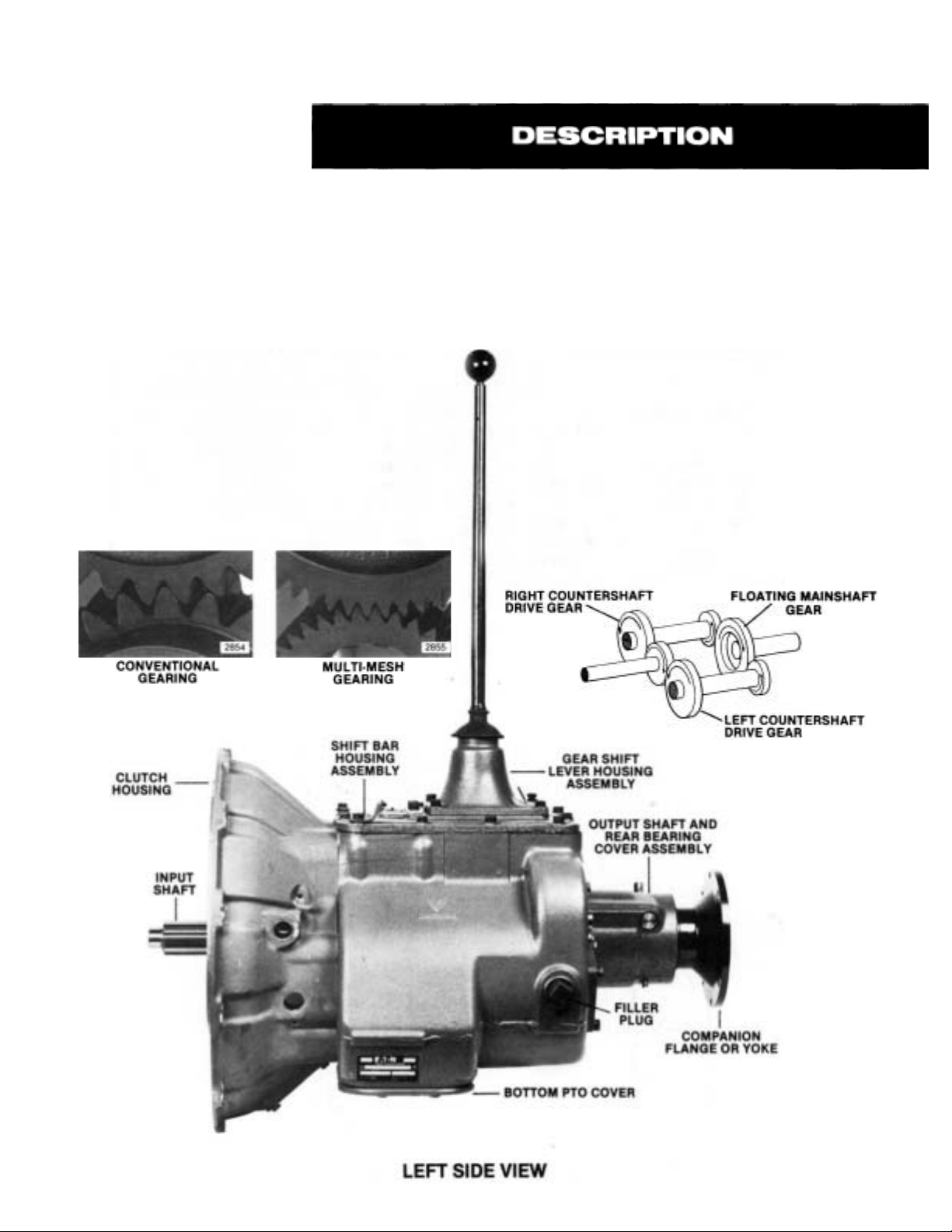
THE T-11605 SERIES TRANSMISSIONS
The New Generation T-11605 series transmissions,
like the proven T-905 series they supersede, are
designed with five forward speeds and one reverse
for medium to heavy duty on-highway vehicles. The
significant difference, however, is that most of the
coarse pitch conventional gearing of the T-905
series has been replaced by the fine pitch "multimesh" gearing of the New Generation Series.
Multi-mesh gearing means there are two or three
teeth per gear always in contact during torque
transfer, instead of just one or two as with conventional gearing. With reduced stress on individual
gear teeth, this multiple contact insures better
distribution of engine torque through a smoother,
less-nosier power flow that ultimately extends
gear and bearing life.
The twin countershaft design, which splits
torque equally between the two shafts to provide a
high torque capacity to weight ratio, remains unchanged. Because of torque splitting, each gear
set carries only half the load, greatly reducing the
face width of each gear. Only the countershaft
gears which mate with multi-mesh mainshaft
gears have been changed to the new gearing concept.
Another unique design feature, also unchanged
from the T-905 series, is the floating gear principle.
The mainshaft gears, when not engaged, "float"
between the countershaft gears, eliminating the
need for gear sleeves and bushings. Only the 1stspeed and reverse gears are of the conventional
gearing type. The remaining forward speed gears
of the mainshaft have been changed to the new
multi-mesh gearing concept.
2865
2857
Page 6

Speed
5th
4th
3rd
2nd
1
St
Reverse
T-11605A
1.00
3.75
6.35
6.48
TO-11605A
.66
2.46 3.75
4.16
4.25
T-11605B
1.00 .86
1.16
2.04
6.35
6.48
TO-11605B
GEAR RATIOS
MODELS
TO-11605C
.85
1.00
1.80
3.32
6.12
6.03
1.00
1.75
3.23
5.46
5.57
T-11605C
1.00
1.18
2.12
3.90
7.20
7.09
GEAR CHART
T-11605D
1.00
1.31
2.05
3.23
5.46
5.57
TO-11605Dl T-11605M T-11605F
2.46 2.66 3.90
4.16
4.25 5.57
5.46
7.20
7.09
MODEL
T-11605A
TO-11605A
TO-11605B
TO-11605B
T-11605C
TO-11605C
T-11605D
TO-11605D
T-11605M
T-11605F
M.S. = MAINSHAFT
C.S. = COUNTERSHAFT
DRIVE
GEAR
40-T
19646
52-T
19168
40-T
19646
44-T
19166
40-T
19191
44-T
19636
44-T
19166
52-T
19168
44-T
19166
40-T
19191
C.S.
DRIVE
GEAR
75-T
19647
64-T
19167
75-T
19647
71-T
19164
78-T
19190
73-T
19637
71-T
19164
64-T
19167
71-T
19164
78-T
19190
M.S.
4TH
52-T
19171
40-T
19648
44-T
19182
40-T
19648
44-T
19634
40-T
19194
52-T
19171
44-T
19182
52-T
19171
50-T
19984
C.S.
4TH
64-T
19175
75-T
19649
71-T
19181
75-T
19649
73-T
19635
78-T
19186
64-T
19175
71-T
19181
64-T
19175
67-T
19985
M.S.
3RD
56-T
19612
56-T
19612
50-T
19620
50-T
19620
50-T
19620
50-T
19620
56-T
19612
56-T
19612
50-T
19620
50-T
19620
C.S.
3RD
44-T
19613
44-T
19613
46-T
19621
46-T
19621
46-T
19621
46-T
19621
44-T
19613
44-T
19613
46-T
19621
46-T
19621
M.S.
2ND
66-T
19177
66-T
19177
66-T
19177
66-T
19177
66-T
19177
66-T
19177
66-T
19177
66-T
19177
56-T
19624
66-T
19177
GEAR SHIFT PATTERN
C.S.
2ND
33-T
19178
33-T
19178
33-T
19178
33-T
19178
33-T
19178
33-T
19178
33-T
19178
33-T
19178
34-T
19625
33-T
19178
M.S.
1ST
44-T
19082
44-T
19082
44-T
19082
44-T
19082
48-T
15470
48-T
15470
44-T
19082
44-T
19082
44-T
19082
48-T
15470
C.S.
WITH
1ST
13-T
14720
13-T
14720
13-T
14720
13-T
14720
13-T
15475
13-T
15475
13-T
14720
13-T
14720
13-T
14720
13-T
15475
C.S.
WITH
REV.
11-T
14720
11-T
14720
11-T
14720
11-T
14720
11-T
15475
11-T
15475
11-T
14720
11-T
14720
11-T
14720
11-T
15475
2858
Shifting Diagram for
T-1 1605 Model Transmissions
2859
Shifting Diagram for
TO-1 1605 Model Transmissions
Page 7

Clutch Release Mechanism—
Push-type clutches-single and
2-Plate – Clutch release bearing car-
rier, release bearing, extended front
bearing cover, release yoke, pedal
shafts and pedal adjusting arm furnished.
Pull-Type 2-Plate Clutches —
ing cover machined for clutch brake
furnished. Secure release yoke, pedal
shafts, and pedal adjusting arm from
clutch manufacturer.
Flat bear-
Torque Capacity—
Diesel engines up to 370 hp, 1150
Ibs.-ft. torque (1559 N.m).
Torque rating is to be used as a guide
and not as an approval. For an approval, submit complete vehicle specifications as outlined on Specification
Form No. 62-14.
Speedometer Drive—
Provision is made in the rear bearing
cover for the installation of speedometer gears and attachment of cable.
Power Take-Off–
Openings—SAE Standard.
Right Side—Regular duty type, 6-bolt,
short length.
Bottom—Heavy duty type, 8-bolt.
PTO Gears—
Right Side—45-tooth, 6/8 pitch gear.
Bottom—47-tooth, 6/8 pitch gear.
PTO Drive Gear Speeds—
Both openings, turning at engine
speed:
T-11605A, T-11605 B . . . . . . . . . . ...533
TO-11605A, TO-11605D . . . . . . . ...813
TO-11605B, T-11605D,
T-11605 M . . . . . . . . . . . . . . . . ...619
T-11605C, T-11605 F . . . . . . . . . . . ..513
TO-11605C . . . . . . . . . . . . . . . . . . ..603
Constant mesh type PTO required on
all overdrive models, both openings;
on T-11605C models, both openings;
and on T-11605B right side. (PTO gears
are conventional mesh, not multimesh.)
Reverse Light Switch—
Provision is made in the shift bar housing for the installation of a reverse light
switch.
Weight—
With Standard Controls, SAE No. 1
aluminum clutch housing, less clutch
release parts—
429 lbs. (195 Kg).
Oil Capacity–
Approximately 22 pints (10 Liters),
depending upon inclination of engine
and transmission.
Note: Fill to level of case filler opening.
Magnetic Oil Cleaners—
Two magnetic discs are installed in
bottom of case to catch and hold
metallic particles deposited in the oil.
Page 8
PROPER LUBRICATION . . .
THE KEY TO LONG
TRANSMISSION LIFE
Proper lubrication procedures are the key to a good
all-round maintenance program. If the oil is not doing its job, or if the oil level is ignored, all the
maintenance procedures in the world are not going
to keep the transmission running or assure long
transmission life.
Oil is important, because here are some of the
things it must do:
■ Provide a protective film —To
protect surface of heavily loaded
parts such as gear teeth and
bearings, thus preventing metal
to metal contact which causes
scoring, scuffing and seizure.
Act as a coolant—To dissipate
heat.
Have sufficient fluidity—To
follow, coat and cushion all
loaded surfaces.
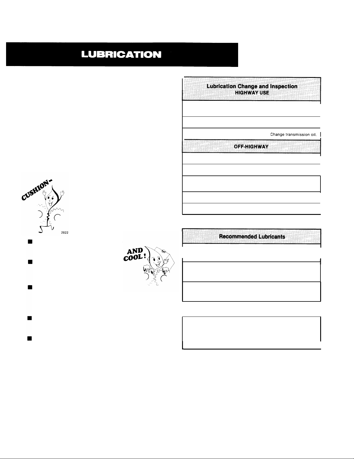
First 3,000 to
5,000 miles (4827 to 8045 Km)
Every 10,000 miles (16090 Km)
Every 50,000 miles (80450 Km)
First 30 hours Change transmission oil on new units.
Every 40 hours
Every 500 hours
Every 1,000 hours
Change oil filter element, if so equipped, at each oil change,
I
Heavy Duty Engine Oil
MIL-L-2104C or MIL-L-46152
Type
or API-SF or API-CD
Change transmission oil on new units.
Inspect Oil Level. Check for leaks.
Inspect oil level. Check for leaks.
Change transmission oil where severe dirt
Grade
(SAE)
50
40
30
conditions exist.
Change transmission oil
(Normal of off-highwav use).
Ambient
Temperature
Above 10°F.
Above 10°F.
Below 10°F.
I
I
I
I
I
I
I
Be chemically stable—To with-
stand heat and agitation with-
2823
out separation, gumming-up,
oxidizing or corroding.
Be non-foaming—To prevent excessive foam
and increased volume under severe conditions.
Be free of sediment and water—To prevent
sludge and rust.
Fuller Transmissions are designed so that the internal parts operate in a bath of oil circulated by the
motion of gears and shafts. Grey iron parts have
built-in channels where needed, to help lubricate
bearings and shafts.
Thus, all parts will be amply lubricated if these
procedures are closely followed:
1.
Maintain oil level. Inspect regularly.
2.
Change oil regularly.
3.
Use the correct grade and type of oil.
Buy from a reputable dealer.
4.
Mineral Gear Oil with rust
and oxidation inhibitor
API-GL-1
Mild EP Gear Oil*
MI L-L-2105 or API-G L-4
I
Multipurpose Gear Oil*
MIL-L-2105B or MIL-L-2105C
or API-G L-5
*Mild EP gear oil or multi-purpose gear oil are not recommended when
lubricant operating temperatures are above 230°F (110°C).
Do not use oil additives, friction modifiers or synthetic lubricants.
Fahrenheit to Celsius: — 40°F = — 40°C
— 15°F = — 26°C
10°F = 12°C
70°F = 21°C
100°F = 38°C
90
80W
90
80W
85W140
80W140
90
80W90
80W
75W
Above 10°F.
Below 10°F.
10” F. to 100°F.
-15” F. to 70°F.
Above 10°F.
Above — 15°F.
10°F. to 100°F.
— 15° F. to 100°F.
— 15°F. to 70°F.
— 40°F.to —150°F.
I
I
2824
Page 9

Proper Oil Level
Make sure oil is level with filler opening. Because
you can reach oil with your finger does not mean
oil is at proper level.
2825
Draining Oil
Drain transmission while oil is warm. To drain oil
remove the drain plug at bottom of case. Clean the
drain plug before re-installing.
Refilling
Clean area around filler plug and remove plug from
side of case. Fill transmission to the level of the
filler opening. If transmission has two filler openings, fill to level of rear opening on single countershaft models; fill to level of both openings on twin
countershaft models.
The exact amount of oil will depend on the
transmission inclination and model. In every in-
stance, fill to the level of the filler opening.
Do not over fill—this will cause oil to be forced
out of the case through mainshaft openings.
Proper Lubrication Levels
Transmission Mounting Angle
Adding Oil
It is recommended that types and brands of oil not
be intermixed because of possible incompatibility.
Operating Temperatures
The Transmission should not be operated consistently at temperatures above 250° F (120°C).
However, intermittent operating temperatures to
300” F (149°C) will not harm the transmission.
Operating temperatures above 250°F increase the
lubricant’s rate of oxidation and shortens its effective life. When the transmission is operated inter-
mittently above 250” F, heavy duty engine oil pro-
vides the best oxidation resistance. When the
average operating temperature is above 250°F, the
transmission may require more frequent oil
changes or external cooling.
The following conditions in any combination
can cause operating temperatures of over 250°F:
(1) operating consistently at slow speeds, (2) high
ambient temperatures, (3) restricted air flow
around transmission, (4) exhaust system too close
to transmission, (5) high horsepower, overdrive
operation.
External oil coolers are available to reduce
operating temperatures when the above conditions are encountered.
2826
If the transmission operating angle is more than
12 degrees, improper lubrication can occur. The
operating angle is the transmission mounting
angle in the chassis plus the percent of upgrade
(expressed in degrees).
The above chart illustrates the safe percent of
upgrade on which the transmission can be used
with various chassis mounting angles. For example: If you have a 4 degree transmission mounting
angle, then 8 degrees (or 14 percent of grade) is
equal to the limit of 12 degrees. If you have a O
degree mounting angle, the transmission can be
operated on a 12 degree (21 percent) grade.
Anytime the transmission operating angle of 12
degrees is exceeded for an extended period of time
the transmission should be equipped with an oil
pump or cooler kit to insure proper lubrication.
Note on the chart the effect low oil levels can
have on safe operating angles. Allowing the oil
level to fall 1/2“ below the filler plug hole reduces
the degree of grade by approximately 3 degrees
(5.5 percent).
Proper Lubrication Levels are Important!
Page 10

PREVENTIVE
MAINTENANCE
Page 11

PREVENTIVE MAINTENANCE CHECK CHART
CHECKS WITHOUT PARTIAL
DISASSEMBLY OF CHASSIS OR CAB
1. Clutch Housing Mounting
a. Check all capscrews in bolt circle of clutch
housing for looseness.
2. Clutch Pedal Shaft and Bores
a. Pry upward on shafts to check wear.
b. If excessive movement is found, remove
clutch release mechanism and check bush-
ings in bores and wear on shafts.
3. Clutch Release Bearing
a. Remove hand hole cover and check radial and
axial clearance in release bearing.
b. Check relative position of thrust surface of
release bearing with thrust sleeve on push
type clutches.
4. Capscrews and Gaskets
a. Check all capscrews, especially those on
PTO covers and rear bearing covers for
looseness which would cause oil leakage.
See Torque Recommendations Section.
b. Check PTO opening and rear bearing covers
for oil leakage due to faulty gasket.
5. Gear Lubricant
a. Change at specified service intervals.
b. Use only gear oils as recommended. See
Lubrication Section.
6. Filler and Drain Plugs
a. Remove filler plug and check level of lubri-
cant at specified intervals. Tighten filler and
drain plugs securely.
8. Gear Shift Lever Housing
Assembly
Remove the gear shift lever housing
a.
assembly from transmission.
b.
Check tension spring and washer for set and
wear.
Check the gear shift lever pivot or spade pin
c.
and pin slot for wear.
Check bottom end of gear shift Iever for wear
d.
and check slot of yokes and blocks in shift
bar housing for wear at contact points with
shift lever.
CHECKS WITH DRIVE LINE DROPPED
9.
Universal Joint Companion Flange or
Yoke Nut
a. Check for tightness. Tighten to recom-
mended torque.
CHECKS WITH UNIVERSAL JOINT
COMPANION FLANGE OR YOKE REMOVED
10. Splines on Output Shaft
a. Check for wear from movement and chuck-
ing action of the universal joint companion
flange or yoke.
11. Mainshaft Rear Bearing Cover
a. Check oil seal for wear.
12. Output Shaft
a. Pry upward against output shaft to check
radial clearance in mainshaft rear bearing.
7. Gear Shift Lever
a. Check for looseness and free play in housing.
If lever is loose in housing, proceed with
Check No. 8.
Page 12
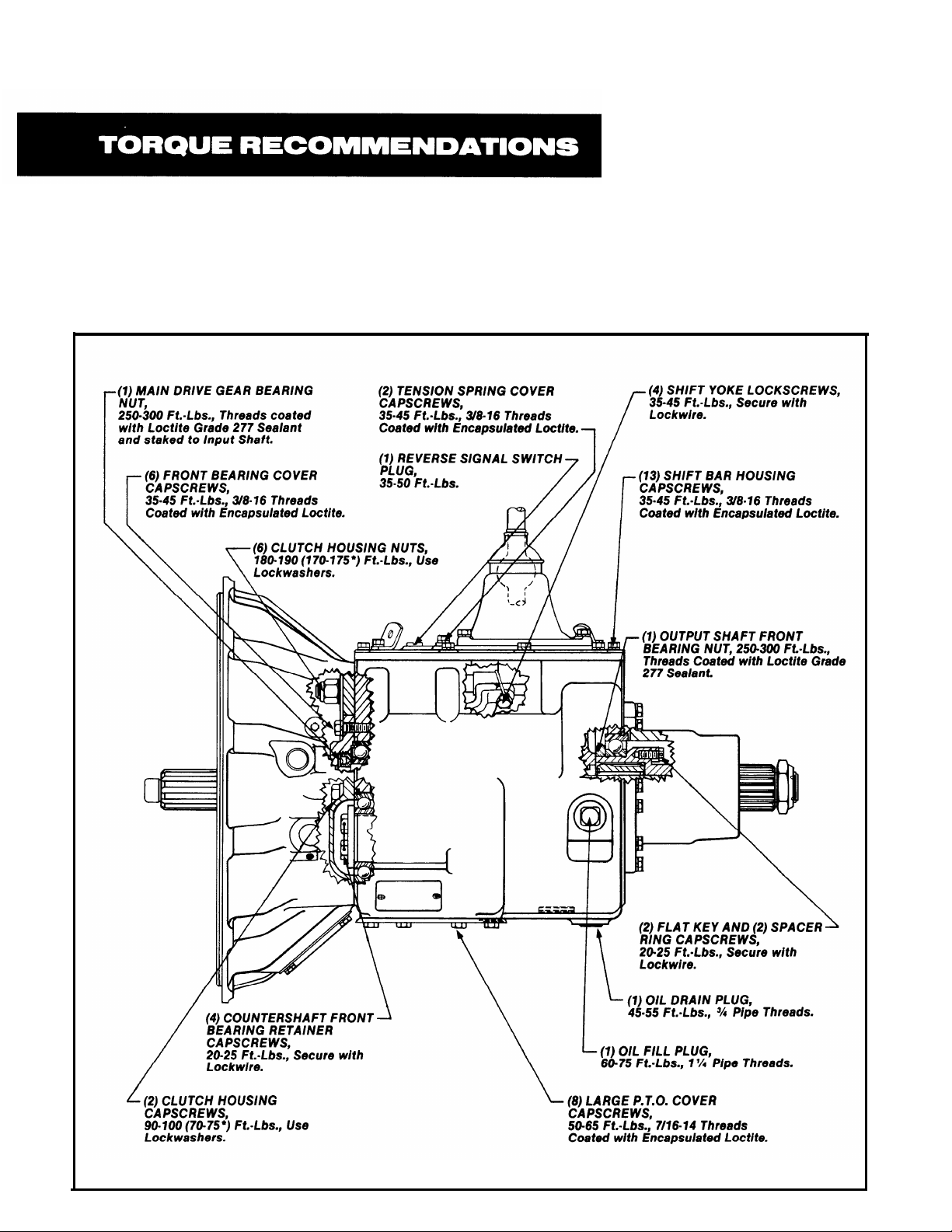
Correct torque application is extremely important to assure long transmission life and dependable perfor-
mance. Over-tightening or under-tightening can result in a loose installation and, in many instances, eventually cause damage to transmission gears, shafts, and/or bearings. Use a torque wrench whenever possible
to ensure proper ft.-lbs. ratings. Do not torque capscrews dry.
Recommended torque ratings, location, and thread sizes of capscrews and nuts incorporated into these
transmissions are provided on the following illustrations.
*With Aluminum Clutch Housing.
2861
Page 13

I
TORQUE
--
(1)
OUTPUT
or
Yoke),
400-450 Ft.·Lbs., Oiled
RECOMMENDATIONS
SHAFT
NUT
(For
Companion Flange
at
Vehicle
Installation.
(4)
GEAR SHIFT LEVER HOUSING CAPSCREWS,
35·45 Ft.·Lbs.,
Encapsulated
318·16
Loctite.
Threads
Coated
with
1
COUNTERSHAFT REAR BEARING
(8)
CAPSCREWS, 1 1 35-45 Ft.-Lbs.,
(
35-45 Ft.·Lbs.,
\
318-16
Threads. \ /
~
A!l
I//?-!
\ft!_ . J
b::1
1'
l\
COVE~'
o
O
~
=====
~rt\\.
®
(~
~~
',
\LJ
l
~
~
~
\ I
·~1
\ R I
rl~'-
r.A~!~$_H_AfT
I
CAPSCREWS,
~
rilant.
~
II
~~
_j
REAR BEARING COVER
318-16
Threads.
(1) SPEEDOMETER HOUSING
PLUG,
35-75
Threeds, Use Hydraulic
Fl.·Lbs.,
13116-20
'
~\
§ \
(4) CLUTCH HOUSING
CAPSCREWS,
20-25 Ft.-Lbs.,
5116-18
(2)
REVERSE IDLER
25-35 Ft.-Lbs., Use Lockwashers.
HAND
HOLE COVER J
Threads.
SHAFT
LOCK
CAPSCREWS,J
I
(6)
SMALL
20-25
Encapsulated
P.
T.O.
Ft.-Lbs., 3i8-16 Threads Coated
COVER
Loctite.
I
l1)
THERMOCOUPLE PLUG,
40-50 Ft.-Lbs., % Pipe Threads.
CAPSCREWS,~
with
2862
Page 14

PROPER TIMING PROCEDURES
FOR TIMING
FOR PROPER TIMING
Like other Fuller twin countershaft models, the
T-11605 series transmissions are “timed” at
assembly. Consequently, when the rebuilding of
these units is called for, it is essential that proper
timing procedures are carried out during reassembly and installation. Proper timing assures that the
countershaft gear teeth will come into contact with
the mating mainshaft gear teeth at the same time,
allowing the mainshaft gears to center on the mainshaft and split the load between the countershaft
gear assemblies. If improperly timed, however, the
mainshaft gears would climb out of equilibrium,
resulting in unequal tooth contact between
meshing gears that would lead to more serious
damage occurring to the transmission later.
By design, the timing of only one set of gears is
necessary—the drive gear set. It is a rather simple
procedure, consisting of marking the proper teeth
of the main and countershaft drive gears prior to installation of the complete assemblies in the case
and meshing those marked gear teeth during
assembly.
Carefully following the step-by-step procedures
given here should enable even the most inexperienced persons in transmission rebuilding to
successfully and properly time these units.
A. Marking countershaft drive gear teeth.
1. Prior to placing each countershaft assembly
into case, clearly mark on each drive gear the
gear tooth which is directly over the keyway
in gear. (See illustration A.) This tooth is
stamped with an “O” to aid identification.
B.c.Marking main drive gear teeth.
Mark any two adjacent teeth on the main
1.
drive gear.
2.
Mark the two adjacent teeth on the main
drive gear which are directly opposite the
first set marked. There should be an equal
number of teeth between the markings on
each side of gear. (See Illustration B.)
B. MAIN DRIVE GEAR TEETH
CORRECTLY MARKED
FOR TIMING
Meshing marked countershaft drive
gear teeth with marked main drive
gear teeth. (After installing main drive
gear and mainshaft assemblies, the
countershaft bearings are installed to
complete countershaft installation.)
1. When installing bearings on the left counter-
shaft, mesh the marked countershaft drive
gear tooth between two marked teeth on the
main drive gear. Repeat the procedure when
installing the right countershaft bearings.
(See Illustration C.)
COUNTERSHAFT DRIVE GEAR
A. TOOTH ON
DIRECTLY OVER
KEYWAY MARKED
C. COUNTERSHAFT DRIVE GEAR TEETH
MESHED WITH MAIN DRIVE GEAR TEETH
Page 15

REMOVAL AND DISASSEMBLY
It is assumed in the detailed Removal and Disassembly instructions that the lubricant has been
drained from the transmission and the unit has
been removed from the chassis. Although the
removal of the gear shift lever housing assembly is
included in the Shifting Controls Section, this
assembly must first be removed from the transmission before removing unit from the vehicle.
FOLLOW EACH PROCEDURE CLOSELY IN EACH
SECTION, MAKING USE OF BOTH THE TEXT AND
PICTURES.
1. BEARINGS — Carefully wash and relubricate all
reusable bearings as removed and protectively
wrap until ready for use. Remove bearings planned
to be reused with pullers designed for this purpose.
2. ASSEMBLIES — When disassembling the various
assemblies, such as the mainshaft, countershafts,
and shift bar housing, lay all parts on a clean bench
in the same sequence as removed. This procedure
will simplify reassembly and reduce the possibility
of losing parts.
INSPECTION
3. SNAP RINGS — Remove snap rings with pliers
designed for this purpose. Snap rings removed in
this manner can be reused.
4. INPUT SHAFT — The input shaft can be removed
from transmission without removing the countershafts, mainshaft, or drive gear. Special procedures
are required and provided in the Changing Input
Shaft Section of this manual.
5. CLEANLINESS — Provide yourself with a clean
place to work. It is important that no dirt or foreign
material enters the unit during repairs. Dirt is an
abrasive and can damage bearings. It is always
good practice to clean the outside of the unit before
starting the planned disassembly.
6. WHEN DRIVING — Always apply force to shafts,
housings, etc., with restraint. Movement of some
parts is restricted. Never apply force to the part being driven after it stops solidly. The use of soft hammers, bars and mauls for all disassembly work is
recommended.
Before reassembling the transmission, the individ-
ual parts should be carefully checked to eliminate
those which should not be reused due to abnormal
or excessive wear or damage. This inspection procedure should be carefully followed to insure the
continued performance and renewed life of the
rebuilt unit with the genuine Fuller parts used.
Since the cost of a new part is generally a small
fraction of the total cost of downtime and labor, the
reuse of a questionable part which could lead to ad-
ditional repairs at a later date is not advisable. With
consideration also given to the unit’s history,
mileage, application, etc., good judgment stemming from product knowledge and experience can
be used in determining the reuse or replacement of
any transmission part.
The recommended inspection procedures are
provided in the following check list:
A. BEARINGS
1. Wash all bearings in clean solvent. Check balls,
rollers and raceways for pitting, discoloration, and
spalled areas. Replace bearings that are pitted,
discolored, or spalIed.
2. Lubricate bearings that are not pitted, discolored,
or spalled and check for axial and radial clearances.
Replace bearings with excessive clearances.
3. Check bearing fits for damaged case bores. If
bearing outer races spin freely in the bores, the case
should be replaced.
B. GEARS
1. Check gear teeth for frosting and pitting. Frosting
of gear tooth faces present little or no threat of
transmission failure. Often in continued operation
of the unit, frosted gears will “heal” themselves and
not progress to the pitting stage. And in most cases,
gears with light to moderate pitted teeth have considerable gear life remaining and can be reused. But
gears with advanced stage pitting are destructive
and should be replaced.
2. Check for gears with clutching teeth abnormally
worn, tapered, or reduced in length from clashing in
shifting. Replace gears found in any of these condi-
tions.
3. Check axial clearance of gears. Where excessive
clearance is found, check gear snap ring, washer,
spacer, and gear hub for excessive wear. Maintain
.005” to .012” axial clearance on mainshaft forward
speed gears, .005” minimum on reverse gear.
Page 16

INSPECTION (Cent’d.)
C. SPLINES
1. Check splines on all shafts for wear. If sliding
clutch gears, companion flange, or clutch hub have
worn into the sides of the splines, replace the
specific shaft affected.
D. TOLERANCE/LIMIT WASHERS
1. Check surfaces of all limit washers. Washers
scored or reduced in thickness should be replaced.
E. REVERSE IDLER GEAR ASSEMBLIES
1. Check bearing sleeves for wear from action of
roller bearings.
F. GRAY IRON PARTS
1. Check all gray iron parts for cracks and breaks.
Replace or repair parts found to be damaged. Heavy
castings may be welded or brazed provided the
cracks do not extend into bearing bores or bolting
surfaces. When doing either A.C. or D.C. welding,
however, never place the ground so as to allow current to pass through the transmission.
G. CLUTCH RELEASE PARTS
1. Check clutch release parts. Replace yokes worn
at cam surfaces and bearing carrier worn at contact
pads.
2. Check pedal shafts. Replace those worn at bearing surfaces.
L GEAR SHIFT LEVER HOUSING
ASSEMBLY
1. Check spring tension on shift lever. Replace ten-
sion spring and washer if lever moves too freely.
2. If housing is disassembled, check pivot or spade
pin and corresponding slot in lever for wear.
Replace both parts if excessively worn.
J. BEARING COVERS
1. Check covers for wear from thrust of adjacent
bearing. Replace covers damaged from thrust of
bearing outer race.
2. Check bores of covers for wear. Replace those
worn oversize.
K. OIL RETURN THREADS AND SEALS
1. Check oil return threads in front bearing cover. If
sealing action of threads has been destroyed by
contact with input shaft, replace bearing cover.
2. Check oil seal in mainshaft rear bearing cover. If
sealing action of lip has been destroyed, replace
seal.
L. SLIDING CLUTCHES
1. Check all shift yokes and yoke slots in sliding
clutches for extreme wear or discoloration from
heat.
2. Check engaging teeth of sliding clutches for partial engagement pattern.
H. SHIFT BAR HOUSING ASSEMBLY
1. Check for wear on shift yokes and blocks at pads
and lever slot. Replace excessively worn parts.
2. Check yokes for correct alignment. Replace
sprung yokes.
3. Check Iockscrews in yokes and blocks. Tighten
and re-wire those found loose.
4. If housing has been disassembled, check neutral
notches of shift bars for wear from interlock balls.
Bars indented at points adjacent to the neutral
notch should be replaced.
M. FRONT BEARING COVER
1. Check inside hub of front bearing cover for wear
caused by backing off of drive gear bearing nut.
N. O= RINGS
1. Check all O-rings for cracks or distortion.
Replace if worn.
Page 17

REASSEMBLY AND INSTALLATION
Since it is important that dirt and other foreign
materials be kept out of the unit during reassembly,
make sure the interiors of the case and housing are
thoroughly cleaned before rebuilding begins. Dirt is
an abrasive and can damage polished surfaces of
bearings and washers.
Use the following precautions during reassembly
and installation:
1. GASKETS — Use new gaskets throughout the
transmission as it is being rebuilt. Make sure all
gaskets are installed, as omission of any gasket
can result in oil Ieakage or misalignment of bearing
covers.
2. CAPSCREWS — TO prevent oil leakage, use
thread sealant on all capscrews. For recommended
torque ratings, see Torque Recommendations
Section.
3. O-RINGS — Lubricate all O-rings with silicone
lubricant.
4. ASSEMBLY — Refer to the illustrations provided
in the Removal and Disassembly Section as a guide
to reassembly.
5. INITIAL LUBRICATION — Coat all limit washers
and splines of shafts with Lubriplate during
reassembly to prevent scoring and galling of such
parts.
6. AXIAL CLEARANCES — Maintain original axial
clearances of .005” to .012” for mainshaft forward
speed gears; .005” minimum for mainshaft reverse
gear.
7. BEARINGS — Use of flange-end bearing drivers
are recommended for the installation of bearings.
See Tool Reference Section for specific tool recom-
mendations. These special drivers apply equal
force to both bearing races, preventing damage to
balls and races while maintaining correct bearing
alignment with bore and shaft.
8. UNIVERSAL JOINT COMPANION FLANGE OR
YOKE — Pull the companion flange or yoke tightly
into place with the mainshaft nut, using 450-500
foot-pounds of torque. Make sure the speedometer
gear has been installed on yoke. If a speedometer
gear is not used, a replacement spacer of the same
width must be installed. Failure to pull the compan-
ion flange or yoke tightly into place will permit the
output shaft to move axially with resultant damage
to the rear bearing.
Page 18
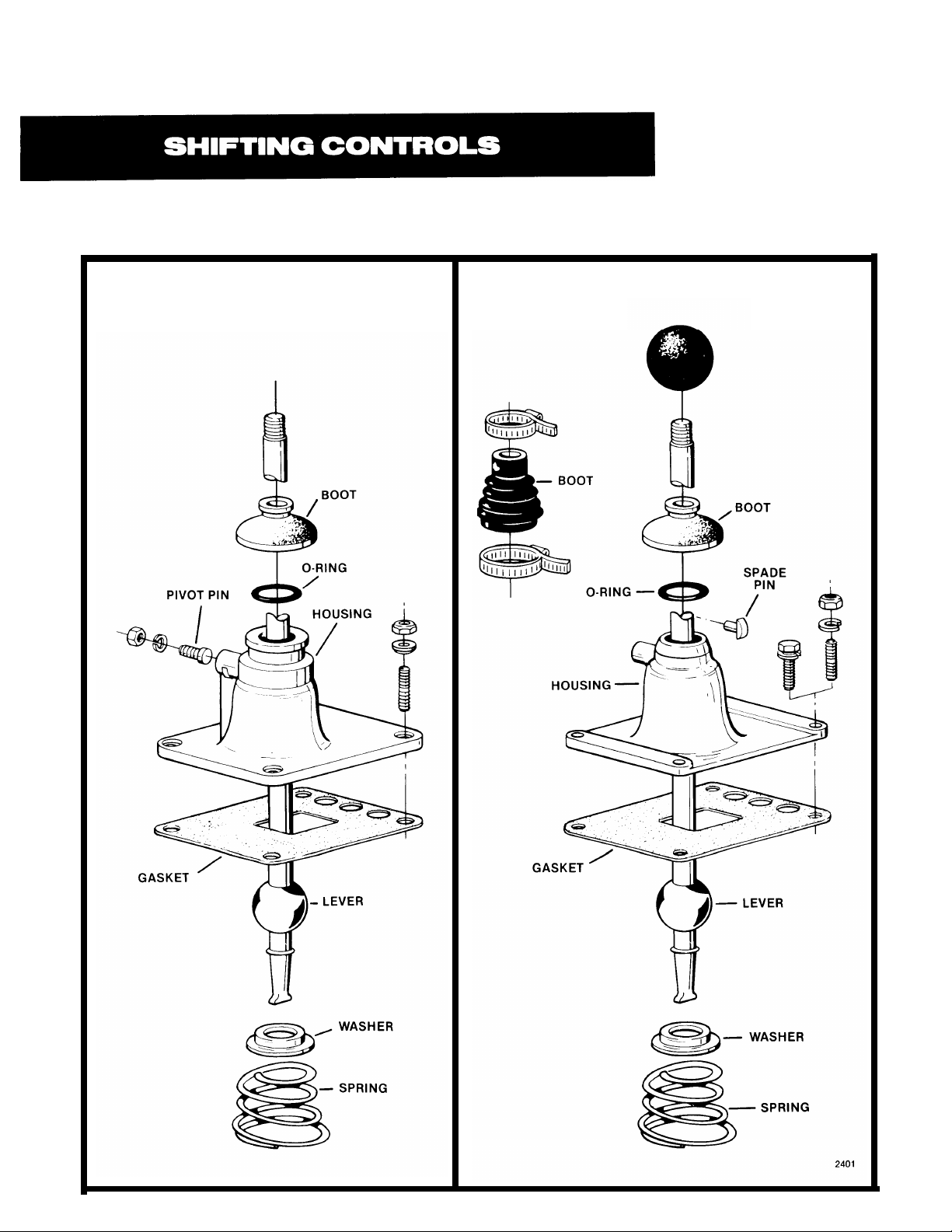
I. GEAR SHlFT LEVER HOUSING ASSEMBLY
OLD STYLE
NEW STYLE
Page 19

1. Install the spade pin or pivot pin, nut and washer
in the bore in the housing. If previously removed,
install the O-ring in the groove.
2.
Secure the housing in a vise and use a large
screwdriver to twist between the spring and side
of the housing, forcing the spring from under the
three lugs. Do one coil at a time. Remove the
spring.
3.
Remove the washer and gear shift lever from
housing once the rubber boot and ball grip have
been removed from lever.
4.
Remove the spade pin or pivot pin, nut and
washer from the bore in the housing. If
necessary, remove the O-ring from the housing.
Page 20

B. Reassembly
1.
Install the spade pin or pivot pin, nut and
in the bore in the housing. If previously re
install the O-ring in the groove.
washer
moved,
4. Remove assembly from vise
rubber boot over the gear
against neck of housing.
and install the
shift lever and
2.
With the gear shift lever positioned in housing
by spade or pivot pin in lever ball slot. install
the tension spring washer over
with dished-side up.
3.
Seat the tension spring under the lugs in the
housing, seating one coil at a time. Use of a
spring driving tool is recommended.
the lever ball
5. Install ball grip on shift lever.
NOTE: For detailed installation instructions of gear
shift lever housing assembly on shift bar housing
assembly, see Reassembly and Installation Sec-
tion, Part III-B, of this manual.
Page 21

Il. SHIFT BAR HOUSING ASSEMBLY
A. Removal and Disassembly
1. Turn out the attaching capscrews.
2. Jar to break the gasket seal and lift the shift
bar housing from transmission.
NOTE: During disassembly, lay all parts on a clean
bench in the order in which they are removed to
facilitate reassembly. Keep bars not being removed
in the neutral position or interlock parts will lock
bars.
Page 22

3. Turn out the two capscrews and remove the
tension spring cover from top of housing.
5. Tilt housing and remove the tension balls installed under springs.
4. Remove the three tension springs from bores in
housing and the gasket for tension spring
cover.
6. Place the housing in a vise with the left side
up; the long 1st-reverse speed shift bar will be
at the bottom.
7. Cut lockwire and remove Iockscrews from
each bar just prior to its removal.
Page 23

SHIFTING CONTROLS
8. Move the top, 4th-5th speed shift bar to the
front and out of housing, removing shift yoke
from bar.
Move the 2nd-3rd speed shift bar to the front
9.
and out of housing, removing the shift yoke
from bar. As tile neutral notch in bar clears
housing boss, remove the small interlock pin
from bore in neutral notch.
10. Move the bottom, 1st-reverse speed shift bar to
the front and out of housing, removing the shift
yoke and block from bar.
11. Two interlock balls will fall from interlock bail
opening in front boss as the last bar is removed.
Page 24

SHIFTING CONTROLS
B. Reassembly
1. Install the housing in a vise with the left side
up.
NOTE: Shift bars should be installed from the
front with neutral and shift notches to the front.
Keep bars in the neutral position when installed.
4. Install 3/4" interlock ball in bore in front boss.
2. Install the 1st-reverse shift bar in bottom bore
in housing, installing the shift yoke and block
on bar, long hub of each to the front.
3. Install Iockscrew in yoke and block, tighten
and lockwire securely.
Install the 2nd-3rd speed shift bar in center
5.
bore in housing and install shift yoke, long
hub to the rear. At the same time install interlock pin in bore in neutral notch of bar as
notch enters front boss.
Install yoke Iockscrew, tighten and lockwire
6.
securely.
Page 25

7. Install 3/4" interlock ball in bore in front boss.
SHIFTING CONTROLS
10. Remove housing from vise and install the
three shift bar tension balls in bores in top of
housing.
8. Install the 4th-5th speed shift bar in upper
bore in housing installing shift yoke on bar,
fork to the front.
9. Install yoke Iockscrew, tighten and lockwire
securely.
11. Install three tension springs in bores.
12. Place a new tension spring cover gasket into
position on shift bar housing and install
cover. Tighten capscrews to secure.
NOTE: For detailed installation instructions of
shift bar housing assembly on case, see Re-
assembly and Installation Section, Part III-A, of
this manual.
Page 26

from the output shaft.
REMOVAL AND DISASSEMBLY
Ill. COMPANION FLANGE OR YOKE, REAR BEARING COVER
ASSEMBLY, AND CLUTCH HOUSING
A. Removal of Companion Flange or Yoke
1.
Lock the mainshaft by engaging two mainshaft 2. Pull flange or yoke from splines of the output
sliding clutches and turn the elastic stop nut
Page 27

REMOVAL AND DISASSEMBLY
B. Removal and Disassembly of Rear
Bearing Cover Assembly
1. Turn out the attaching caps crews from the rear
bearing cover.
3. Remove the bearing cover and gasket from output shaft.
2. Pry the bearing cover evenly to the rear to unseat
from output shaft bearing.
4. Remove oil seal from cover if necessary.
Page 28

REMOVAL AND DISASSEMBLY
C. Removal of Clutch Housing
NOTE: For models otherwise equipped with Amid-
ship Assembly, refer to illustration provided in Op-
tions Section of this manual.
1. Remove the clutch release mechanism if the
transmission is so equipped.
3. Break gasket seal and pull clutch housing from
case.
Turn out the four capscrews and remove the six
2.
nuts and lockwashers from studs at front of
case.
Page 29

REMOVAL AND DISASSEMBLY
IV. CASE-INNER ASSEMBLIES
A. Removal and Disassembly of
Output Shaft Assembly
1. Remove the speedometer gear, or replacement
spacer, and the bearing washer from output
shaft or from cover.
3. Cut lockwire and turn out the two 5/16-24
capscrews from the two flat retainers or keys.
x 1"
2. Pull the outer bearing from output shaft. (This
wearing may remain in cover. In this case, move
the bearing evenly forward and from cover.)
4. Remove the two flat retainers from bores in output shaft. These retainers maintain the position
of the mainshaft in relation to output shaft.
Page 30

REMOVAL AND DISASSEMBLY
5. Remove output shaft from case bore. Start
assembly to the rear with screwdriver, prying
evenly against bearing snap ring.
8. Place output shaft in vise and remove the bearing nut, left-hand thread.
6. Remove the splined coupler from mains haft, or
from pocket in output shaft.
7. Turn out the two 5/16-24 x 5/8" capscrews and
remove the key spacer ring from output shaft.
9. Press bearing from output shaft.
Page 31

REMOVAL AND DISASSEMBLY
2213
B. Removal and Disassembly of Left
Reverse Idler Gear Assembly
NOTE: The left reverse idler gear must be removed
in order to remove the mainshaft assembly.
1. Move the mainshaft assembly forward as far as
possible and the mainshaft reverse gear to the
rear against case.
3. Engage reverse gear with the 1st-reverse sliding
clutch and move the reverse gear forward
against the 1st speed gear.
2. Remove the snap ring from ID of the mainshaft
reverse gear.
4. Turn out capscrew at rear of transmission and
remove the lock plate from slot in the idler shaft.
Page 32

REMOVAL AND DISASSEMBLY
7.c.If necessary, remove the inner race from idler
gear needle bearing, the needle bearing from
idler gear, and the pipe plug from idler shaft.
5. Use impact puller to withdraw the idler shaft
from case.
Removal of Countershaft
Bearings
NOTE: Although the bearings of both countershafts
are removed in the same manner, it is necessary to
remove the bearings from only the right countershaft to remove the mainshaft assembly from case.
.
.
6. Remove the reverse idler gear and the two thrust
washers from case.
1. Turn out capscrews and remove the rear bearing
cover and gasket from each countershaft.
Page 33

REMOVAL AND DISASSEMBLY
2.
Use a soft punch and maul from inside case to
drive the rear countershaft bearings to the rear
and from case bores. (NOTE: This removal procedure will damage the bearings and should not
be attempted unless replacement of the bear-
ings is planned.)
5. With the same soft bar and maul on the rear of
each countershaft, drive the countershafts forward to expose the front bearing snap rings.
3. Cut lockwire and remove the two capscrews
and retainer plate from the front of each
countershaft. For models so equipped with
bearing retaining snap rings in groove of
countershafts, remove snap ring from groove
in both countershafts.
4. Use a soft bar and maul to drive each countershaft to the rear approximately 1/2".
,.
.
6. Use a bearing puller to remove the front bearing
from each countershaft.
Page 34

REMOVAL AND DISASSEMBLY
D. Removal and Disassembly of
Mainshaft Assembly
2. Holding 3rd and 4th speed gears, tilt the front of
the mainshaft up and lift assembly from case.
Use caution as the reverse gear is free and can
fall off the shaft.
NOTE: When removing limit washers, spacers and
gears, note their location to facilitate reassembly.
Keep limit washers and spacers with the gear from
1.
With the right countershaft moved toward wall of
case, pull the mainshaft to the rear to free pilot spacer and one limit washer for each gear in the
from pocket of input shaft.
which they were removed. There should be only one
mainshaft assembly.
Page 35

REMOVAL AND DISASSEMBLY
3. Remove the reverse gear from rear of mainshaft.
4.
Remove the 4th-5th
front of mainshaft.
speed sliding clutch from
6. With a small screwdriver, rotate the 4th speed
gear limit washer, recessed within the gear hub,
to align its splines with those of the mainshaft.
7.
Pull the 4th speed gear from front of mainshaft to
remove limit washer, spacer, and gear.
Remove the short key from keyway near front of
5.
mainshaft. This key locks the 4th speed gear
limit washer in position.
Remove the 3rd speed gear and spacer from
8.
front of mainshaft. The 3rd speed gear limit
washer cannot be removed at this time as it is
keyed in groove of mainshaft.
Page 36

REMOVAL AND DISASSEMBLY
Rotate reverse gear limit washer to align its
9. Remove the long key retaining snap ring from
slot near rear of mainshaft.
12.
splines with those of the mainshaft and remove
washer.
10. Remove the reverse gear spacer.
11. From rear of mainshaft, pull the long key from
mainshaft keyway.
13. Remove 1st-reverse sliding clutch from mainshaft.
14. With a small screwdriver, rotate the 1st speed
gear limit washer, recessed within the gear hub,
to align its splines with those of the mainshaft.
Page 37

REMOVAL AND DISASSEMBLY
Pull the 1st speed gear from rear of mainshaft to
15.
remove limit washer, spacer, and gear.
16. Remove 2nd speed gear and spacer from mainshaft.
18. Remove the 2nd-3rd speed sliding clutch from
mainshaft.
19. Rotate 3rd speed gear limit washer to align its
splines with those of mainshaft and remove
washer.
17. Rotate 2nd speed gear limit washer to align its
splines with those of the mainshaft and remove
washer.
Page 38

REMOVAL AND DISASSEMBLY
E. Removal and Disassemble of Main
Drive Gear Assembly
NOTE: For models equipped with an Amidship
Assembly in place of a Drive Gear Assembly, refer
to Options Section of this manual.
1. Remove front bearing cover and gasket by turning out capscrews.
2. Use a soft bar and maul from inside case to move
drive gear assembly forward as far as possible to
expose front bearing snap ring from case bore.
Page 39

3. Remove snap ring from front bearing.
REMOVAL AND DISASSEMBLY
5.
Remove drive gear assembly from transmission
by lifting it out through top of case.
4. Use a soft maul, rubber or rawhide mallet to
move input shaft into case, being careful as
not to damage pilot-end.
6. Secure assembly in a vise, pilot end up, on drive
gear O. D. The vise used should be equipped with
either brass jaws or wood blocks to prevent
damage to the teeth of drive gear.
Page 40

REMOVAL AND DISASSEMBLY
7. Use a punch and maul to relieve bearing nut from
shaft, left hand thread.
Remove assembly from vise to press input shaft
9.
through bearing and gear. If necessary, remove
snap ring from drive gear I.D. Check the bushing
in pocket of input shaft and replace if damaged
or worn.
8. Use a drive gear bearing nut remover to turn the
bearing nut from shaft, left hand thread.
Page 41

REMOVAL AND DISASSEMBLY
F. Removal and Disassembly of
Countershaft Assemblies
1. If not previously done so, remove front and rear
bearings of left countershaft as described in Part
C of this section.
2. Move either countershaft assembly to the rear,
lift front of shaft to the center of case by the drive
and PTO gears and remove through top of case.
Repeat same process for other countershaft
assembly.
NOTE: Except for the PTO gears, the left and right
countershaft assemblies are identical, Disassembly of each should be performed in the same manner.
3. For models so equipped with a countershaft
gear retaining snap ring in groove nearest to
drive gear, remove snap ring from countershaft.
4. Press the drive gear, PTO gear, 4th speed gear,
and 3rd speed gear from countershaft. Use caution when pressing ears as it is necessary to
press these gears of in a cluster of four.
?
Page 42

REMOVAL AND DISASSEMBLY
If necessary, remove the key and roll pin from
5. Press the 2nd speed gear from countershaft.
6.
countershaft.
G.
Removal and Disassembly of
Right Reverse Idler Gear Assembly
NOTE: Since the left and right reverse idler gear
assemblies are identical, removal and disassembly
of the Right Reverse Idler Gear Assembly should be
performed in the same manner as described in Part
B of this section.
Page 43

CHANGING INPUT SHAFT
SPECIAL PROCEDURE
In some cases, it may be necessary to replace only
the input shaft due to clutch wear on the splines.
In these instances, the input shaft can be removed without disassembling the transmission for
other than removing the shifting bar housing
assembly. Removal of the clutch housing is optional. Following is the special procedure.
REMOVAL AND DISASSEMBLY
1. Remove gear shift lever housing and shift bar
housing assemblies from transmission.
2. Remove the front bearing cover.
3. Engage the mainshaft sliding clutches in two
gears and remove the drive gear bearing nut.
4. Move the drive gear assembly as far forward as
possible and remove the drive gear bearing.
5. Remove the spacer from input shaft.
6. From the front, remove the snap ring from ID of
drive gear.
7. Pull the input shaft forward and from splines of
drive gear.
REASSEMBLY AND INSTALLATION
1. Install new input shaft into splines of drive gear
just far enough to expose snap ring groove in ID of
drive gear.
2. Install snap ring in ID of drive gear.
3. Install spacer on shaft against drive gear.
4. Install drive gear bearing on shaft and into case
bore.
5. Install a new drive gear bearing nut, left-hand
thread. Clean threads of nut and input shaft before
applying Loctite sealant to threads of both parts.
Use 250-300 ft.-lbs. of torque to tighten nut.
6. Peen nut into milled slots of input shaft.
7. Re-install front bearing cover, shift bar housing
and gear shift lever housing assemblies.
NOTE: The above instructions are for changing the
input shaft only. To change the drive gear, removal
of the mainshaft assembly and the countershaft
bearings is necessary.
Page 44

REASSEMBLY AND INSTALLATION
1. CASE-INNER ASSEMBLIES
A. Reassembly and Installation of
Right Reverse Idler Gear Assembly
1. If previouslv removed, install pipe plug in thread-
ed end of idler shaft.
4. With the two thrust washers in position on each
side of reverse idler gear, slide the idler shaft
through bore in rear of case, gear, washers, and
bore of idler shaft support boss inside case. To
make certain the slot in rear of idler shaft is properly located to secure lock plate with capscrew
in case, align oil channel hole of idler shaft with
that in top of idler shaft support boss.
2. Press need
gear.
3. Insert inner race
e bearing into bore of reverse idler
5. Insert lock plate into slot of idler shaft and
secure with capscrew.
of needle bearing of gear.
Page 45

REASSEMBLY AND INSTALLATION
B. Reassembly of Countershaft
Assemblies
NOTE: Since the left and right countershaft
assemblies are identical, except for the PTO gears,
reassembly of each should be performed in the
same manner.
3. Press the 3rd speed gear on countershaft, long
hub of gear against 2nd speed gear hub.
1. If previously removed, install roll pin and long
key in keyway of countershaft.
2. Align keyway in gear with key in countershaft
and press the 2nd speed gear into position on
shaft, long hub of gear toward front of countershaft.
4. Press the 4th speed gear on countershaft
against 3rd speed gear.
Page 46

REASSEMBLY AND INSTALLATION
For models so equipped with two snap ring
7.
grooves in front of each countershaft, install
countershaft gear retaining snap ring in
groove nearest to drive gear. Do not install
snap ring in other groove of countershaft at
this time, as it is intended for the front bearing
retaining snap ring.
5. Press the power take-off gear on countershaft,
bullet nose teeth against 4th speed gear. (The
left counteshaft assembly has a 47-tooth PTO
gear the right countershaft assembly has a
45-tooth PTO gear. To eliminate confusion dur-
ing installation, mark the appropriate assembly
as "right" and "left".)
6. Press the drive gear on countershaft against
PTO gear.
IMPORTANT: Mark countershaft drive gears for
8.
timing. On the drive gear of each countershaft
assembly, mark the gear tooth stamped with an
"O" that is aligned with the keyway of gear. Use
of toolmakers dye of a highly visible color is
recommended.
Page 47

REASSEMBLY AND INSTALLATION
IMPORTANT: Remove assembly from vise and
8.
mark the drive gear for timing. Mark any two adja-
cent teeth on the drive gear and repeat the same
process for the two adjacent teeth directly opposite the first set marked. Use of toolmakers
dye of a highly visible color is recommended.
11. Install snap ring in drive gear bearing groove.
Remove the snap ring from drive gear bearing.
9.
10.
Spread the partially installed countershaft
assemblies and insert the drive gear assembly
through front bore from inside case. Seat the
drive gear bearing in case bore and move
assembly forward until snap ring groove in
bearing is exposed.
12. Seat bearing in case bore and install the drive
gear bearing cover with new gasket, aligning
the oil return slot in cover with oil return hole in
case. Secure with capscrews.
Page 48

REASSEMBLY AND INSTALLATION
E. Completed Installation of Left
1. Insert countershaft support tool in rear bearing
bore.
Install retainer plate, secure with capscrews,
4.
and lockwire. For models so equipped with
groove in countershaft for front bearing retaining snap ring, install snap ring in groove.
. .
.
2. Mesh the marked tooth of left countershaft drive
gear with either set of two marked timing teeth of
main drive gear.
3. With timing teeth still in mesh, install countershaft front bearing. Center countershaft in case
bore using a small screwdriver inserted through
bearing I.D. and in bell center or either threaded
hole in-end of shaft.
5. Remove countershaft support tool from rear
case bore and install countershaft rear bearing
with the larger I.D. lead chamfer toward front of
transmission. (Note: If damage to original bearing resulted from punch and
replace with new rear bearing.)
maul removal,
Page 49

C. Partial Installation of Countershaft
Assemblies
1. Place the left countershaft assembly with the
47-tooth PTO gear into position in case, small
end through the left rear countershaft bore. Do
not install bearings at this time,
D. Reassembly and Installation of
Main Drive Gear Assembly
1. If previously removed, install the snap ring in I.D.
of main drive gear.
2. Place the right countershaft assembly with the
45-tooth PTO gear into position in case, small
end through right rear countershaft bore. Do not
install bearings at this time.
2. Install the main drive gear on input shaft, engaging internal splines of gear with teeth on shaft,
snap ring of gear toward the front.
3. Install the drive gear spacer on input shaft
against gear.
Page 50

4.
Press the drive gear bearing on input shaft, bearing shield to the front.
Secure assembly in vise, pilot end up, on drive
6.
gear O.D. The vise used should be equipped with
either brass jaws or wood blocks to prevent
damage to the teeth of drive gear. Using a drive
gear bearing nut installer, install the nut on input
shaft, left hand threads, with 250-300 ft. lbs. of
torque.
Clean threads of input shaft and apply Ioctite
5.
grade 277 sealant to threads of new drive gear
bearing nut. Do not reuse old nut.
With a punch and maul, peen the nut into the two
7.
milled slots of input shaft.
Page 51

REASSEMBLY AND INSTALLATION
F. Partial Reassembly of
Output Shaft Assembly
1. Press the front bearing on output shaft, snap ring
to the rear.
3. Install the bearing nut on threads of output shaft
and torque to 250-300 ft. lbs.
2. Clean threads of output shaft and bearing nut.
Apply Ioctite grade 277 sealant to threads of nut.
4. Position the key spacer ring on output shaft
using the two 5/16-24 x 5/8" capscrews, but do not
tighten.
Page 52

REASSEMBLY AND INSTALLATION
G. Reassembly of Mainshaft Assembly
Place mainshaft in vise equipped with brass
1.
jaws or wood blocks, pilot end down. (Note: If
previously removed, install all corresponding
snap rings in mainshaft gears with the exception
of reverse gear.)
3. Install 2nd-3rd speed sliding clutch, aligning
missing internal spline of sliding clutch with key.
Install 3rd speed gear limit washer with flat side
2.
down in 4th groove of mainshaft. Rotate washer
to align splines of washer with those of the mainshaft and install the long key in mainshaft
keyway.
4. Remove key and install 2nd speed gear limit
washer, flat side up, in next groove of mainshaft.
Rotate washer to align splines of washer with
those of mainshaft and reinsert key.
NOTE: The long key is moved downward to engage
each limit washer as they are positioned on mainshaft.
Page 53

REASSEMBLY AND INSTALLATION
5. Install spacer against 2nd speed limit washer.
NOTE: Gear limit washers are internally splined and
locked to mainshaft by key. Gear spacers are exter-
nally splined to engage with splines in gear hubs.
There is one limit washer and one spacer for each
gear in mainshaft assembly.
7.
Install it speed gear, clutching teeth up.
8. Install spacer in 1st speed gear, engaging external splines of spacer with clutching teeth of
gear.
6. Install 2nd speed gear, clutching teeth down.
Engage clutching teeth of gear with external
splines of spacer.
.
Page 54

REASSEMBLY AND INSTALLATION
11.
Insert two large screwdrivers between 1st and
2nd speed gears. Apply slight downward
pressure on screwdriver handles to spread
9. Remove key and install 1st speed limit washer,
flat side against spacer.
gears evenly. Making certain gear hubs are
parallel, insert feeler gage between hubs. Correct axial clearance should be from .005" to
.012". If the clearance is less than the minimum
.005" tolerance, the limit washer in the 1st
speed gear should be replaced by a lower limit
washer. This will increase the axial clearance
between the gears. If the clearance checked is
greater than the maximum .012" tolerance, a
higher limit washer should be installed in the
1st speed gear. This would decrease the axial
clearance between the gears.
10. Rotate washer to align splines of was
those of mainshaft and reinsert key.
her with
Page 55

SETTING CORRECT AXIAL
CLEARANCES FOR
MAINSHAFT GEARS
Axial Clearance (End Play) Limits Are:
Reverse speed gear — Minimum of .005"
Forward speed gears — .005" to .012"
Washers are used to obtain the correct limits; six
thicknesses are available as follows:
LIMITS (INCH)
.248-.250
.253-.255
.258-.260
.263-.265
.268-.270
.273-.275
*
* Note: New style limit washers come in full range
of tolerances and corresponding colors listed
above “plus red”. (Example: “Orange plus red”
limit washer has an inch limit thickness of
.258-.260.)
Refer to Illustrated Parts Lists for washer part
numbers.
Always use the .248-.250” low limit washer (“white”
or “white plus red”) in the 1st and 3rd speed gear
positions as shown at right.
** On overdrive models, the (4th) speed gear
becomes (5th) speed gear.
COLOR CODE
WHITE
GREEN
ORANGE
PURPLE
YELLOW
BLACK
PLUS RED
Page 56

REASSEMBLY AND INSTALLATION
Install 1st-reverse speed sliding clutch, align-
12.
ing missing internal spline of sliding clutch
with key in mainshaft.
14. Install spacer against reverse gear limit washer.
15. Install snap ring in snap ring
mainshaft.
groove at rear of
Remove key and install reverse gear limit
13.
washer, flat side up, in last groove of mainshaft.
Rotate washer to align splines of washer with
those of mainshaft and reinsert key.
Page 57

REASSEMBLY AND INSTALLATION
16. Reposition mainshaft assembly in vise, pilot
end up.
17. Install spacer against flat side of 3rd speed gear
limit washer.
Install 3rd speed gear, clutching teeth down.
18.
Engage clutching teeth of gear with external
splines of spacer.
19. Install 4th speed gear, clutching teeth up,
against 3rd speed gear.
Page 58

REASSEMBLY AND INSTALLATION
20.
Install spacer in 4th speed gear, engaging external splines of spacer with clutching teeth of
gear.
22.
Check axial clearances and make adjustments,
if necessary, between the 3rd and 4th speed
gears in the same manner as performed between the 1st and 2nd speed gears (step #n).
Install 4th speed gear limit washer, flat side
21.
against spacer, in 4th speed gear. Rotate
washer to align splines of washer with those of
mainshaft and install short key in mainshaft
keyway.
Install 4th-5th speed sliding clutch, aligning
23.
missing internal spline of sliding clutch with
key in mainshaft.
Page 59

REASSEMBLY AND INSTALLATION
Remove mainshaft assembly from vise. Install
24.
reverse gear on mainshaft over snap ring in rear,
clutching teeth toward front, and move it
against 1st speed gear, engaging clutching
teeth of gear with external splines of spacer.
H. Partial Installation of Mainshaft
1. Move the right countershaft assembly as far as
possible toward case wall.
2. With the reverse gear as far forward as possible,
install the mainshaft assembly into position in
case, meshing corresponding gears on left
countershaft with those on mainshaft.
Temporarily install the coupler, counterbore
3.
toward front of transmission, and partially
reassembled output shaft assembly, engaging
splines of output shaft with those of coupler, to
center the rear of mainshaft assembly.
Page 60

REASSEMBLY AND INSTALLATION
I. Completed Installation of Right
Countershaft Assembly
NOTE: Left countershaft assembly must remain in
time with main drive gear when timing right counter-
shaft assembly.
With timing teeth still in mesh. install counter-
3.
shaft front-bearing. Center countershaft in case
bore using a small screwdriver inserted through
bearing I.D. and in bell center or either threaded
hole in end of shaft.
1. With the right counteshaft parallel with main-
shaft, mesh the marked tooth of right countershaft drive gear with the remaining two marked
timing teeth of main drive gear.
2. Insert countershaft support tool in rear bearing
bore.
4.
Install retainer plate, secure with capscrews,
and lockwire. For models otherwise equipped
with front bearing retaining snap ring in groove
of countershaft, install snap ring.
Page 61

REASSEMBLY AND INSTALLATION
5.
Remove countershaft support tool from rear
case bore and install countershaft rear bearing
with the larger I.D. lead chamfer toward front of
transmission. (NOTE: If damage to original bearing resulted from punch and maul removal, replace with new rear bearing.)
7.
If properly timed, install both countershaft rear
bearing covers with new gaskets and secure-to
case with capscrews.
J.
Reassembly and Installation of Left
Reverse Idler Gear Assembly
NOTE: Since the left and right reverse idler gear
assemblies are identical, reassembly and installation of the Left Reverse Idler Gear Assembly should
be performed in the same manner as described in
Part I-A of this section.
6.
Shift the mainshaft sliding clutches into all gear
positions with a screwdriver. A sliding clutch
that cannot be shifted into gear indicates that
the drive gear set is out of time. The right
countershaft bearings would then need to be
removed and the countershaft retimed with the
mainshaft. The transmission is properly timed if
the sliding clutches can be shifted into all mainshaft gears. (NOTE: Do not shift the transmission into two gears at the same time. This will
prevent the mainshaft and countershaft assemblies from rotating.)
K. Completed Installation of Mainshaft
Assembly
1.
Remove temporarily installed output shaft
assembly from case bore and coupler from rear
of mainshaft.
Page 62

REASSEMBLY AND INSTALLATION
2. Move the reverse gear to the rear on mainshaft as
far as possible, meshing teeth of gear with teeth
of the two reverse idler gears.
3. With mainshaft forward and reverse gear to the
rear, seat the reverse gear spacer previously installed on shaft in hub of gear, and install the
snap ring in ID of reverse gear.
L. Completed Reassembly and Installation
of Output Shaft Assembly
2. Reinstall output shaft assembly over mainshaft,
seating bearing in case bore. Make sure splines
in output shaft engage splines of coupler.
3. Install two flat retainers in bores of output shaft
to key in slot of m ainshaft.
1. Reinstall coupler on splines of mainshaft with
the counterbore toward the front of transmission.
Page 63

REASSEMBLY AND INSTALLATION
4.
Secure retainers with 5/16-24 x 1" capscrews and
tighten all capscrews in spacer ring evenly. install lockwire to include all four tightened
capscrews in spacer ring.
6. Install bearing washer on output shaft against
outer bearing, chambered I.D. toward bearing.
5. Install outer bearing on output shaft seating it
against shoulder of shaft.
7.
Install the speedometer drive gear or replacement spacer on output shaft against
bearing washer.
Page 64

REASSEMBLY AND INSTALLATION
Il. CLUTCH HOUSING, REAR BEARING COVER ASSEMBLY,
AND COMPANION FLANGE OR YOKE
A. Installation of Clutch Housing
NOTE: For models otherwise equipped with Amid-
ship Assembly, refer to illustration provided in
Options Section of this manual.
Apply white grease to new clutch housing
1.
gasket and install in position on case.
3. Install the six nuts with washers or lockwashers
on studs and tighten. See Torque Recommendations Section.
-
4.5.Install the four capscrews with lockwashers and
tighten. See Torque Recommendations Section.
Install the clutch release mechanism if transmission is so equipped.
2. Place clutch housing in position on the six studs
in front of case, piloting on drive gear cover.
Page 65

REASSEMBLY AND INSTALLATION
B. Reassembly and Installation of Rear
Bearing Cover Assembly
1. Install new oil seal in rear bearing cover if
original seal was previously removed. A spring is
visible on one side of seal. Install this side with
spring toward front of transmission.
C. Installation of Companion Flange
or Yoke
1. Lock
the mainshaft by engaging any two main-
shaft
gears with the sliding clutches.
2. Install rear bearing cover with new gasket evenly
on output shaft to seat outer bearing in cover,
aligning oil slot
case.
3. Install attaching capscrews and tighten t o
secure rear bearing cover to case.
in cover and gasket with hole in
2.
Install companion flange or yoke on output shaft
splines and secure with output shaft nut, using
400-450 ft. lbs. of torque.
Page 66

REASSEMBLY AND INSTALLATION
Ill. SHIFTING CONTROLS
A. Installation of Shift Bar Housing
Assembly
NOTE: For detailed reassembly instructions of shift
bar housing assembly, see Shifting Controls Sec-
tion, Part II-B, of this manual.
3. Make certain that all three shift bars of assembly
are in the neutral position.
1. Place all three mainshaft sliding clutches in the
neutral position.
2. Apply white grease to new shift bar housing
gasket and install in position on case.
4. Install the shift bar housing assembly on
transmission, fitting shift yokes into corresponding yoke grooves of mainshaft sliding clutches.
5. Install the thirteen capscrews in flange holes of
housing and tighten, remembering to include the
two lifting eyes in position on housing corners
opposite each other.
Page 67

REASSEMBLY AND INSTALLATION
B. Installation of Gear Shift Lever Housing
Assembly.
NOTE: For detailed reassembly instructions of
gear shift lever housing assembly, see Shifting
Controls Section, Part l-B, of this manual.
Install gear shift lever housing assembly, fitting
3.
tang of-gear lever into notches of shift bar hous-
ing assembly blocks and yokes.
4. Install the four capscrews in flange holes of
housing and tighten.
1. Make certain that the shift block notches in
the shift bar housing assembly are aligned in
the neutral position.
2. Apply white grease to new gear shift lever
housing gasket and install in position on
shift bar housing assembly.
Page 68

TOOL REFERENCE
Some repair procedures pictured in this manual obtained from a regular tool supplier or made
show the use of specialized tools. Their actual
use is recommended as they make transmission
repair easier, faster, and prevent costly damage
to critical parts.
But for the most part, ordinary mechanic's
tools such as socket wrenches, screwdrivers,
etc., and other standard shop items such as a
press, mauls and soft bars are all that is needed Technical Service Dept.
to successfully disassemble and reassemble any
Fuller Transmission.
The specialized tools listed below can be
from dimensions as required by the individual
user. Detailed Fuller prints and a booklet which
gives the use and description of these tools are
available upon request by writing:
Eaton Corporation
Transmission Division
P.O. Box 4013
Kalamazoo, Michigan 49003
PAGE
20
29
32
33
36, 39, 49, 56
40, 48
50,60 Countershaft Support Tool
Impact Puller (%-13 Threaded End)
Drive Gear Bearing Nut Remover/lnstaller
Tension Spring Driver
Bearing Puller, Large
Countershaft Bearing Puller
Snap Ring Pliers, Large
TOOL
(Jaw Type)
HOW OBTAINED
Made from Fuller
Print T-1 1938
Tool Supplier
Tool Supplier
Made from Fuller
Print T-9824
Tool Supplier
Made from Fuller Print
T-22553-D or T-22553-C
Made from Fuller
Print T-22247
50,60,61,63,65
65
65
*Dimensions necessary to determine specific tool number required.
Bearing Drivers (Flange-End Type)
Oil Seal Driver
Torque Wrench, 1000 Ft.-Lb. Capacity
Made from Fuller Print
Print Series T-18042*
Made from Fuller Print
T-1 8088-20 or T-18088-34
Tool Supplier
Page 69

Copyright Eaton Corporation, 2012.
Eaton hereby grant their customers,
vendors, or distributors permission
to freely copy, reproduce and/or
distribute this document in printed
format. It may be copied only in
its entirety without any changes or
modifications. THIS INFORMATION
IS NOT INTENDED FOR SALE OR
RESALE, AND THIS NOTICE MUST
REMAIN ON ALL COPIES.
Note: Features and specifications
listed in this document are subject to
change without notice and represent
the maximum capabilities of the
software and products with all options
installed. Although every attempt has
been made to ensure the accuracy of
information contained within, Eaton
makes no representation about the
completeness, correctness or accuracy
and assumes no responsibility for
any errors or omissions. Features and
functionality may vary depending on
selected options.
For spec’ing or service assistance,
call 1-800-826-HELP (4357) or visit
www.eaton.com/roadranger.
In Mexico, call 001-800-826-4357.
Roadranger: Eaton and trusted partners
providing the best products and services in the
industry, ensuring more time on the road.
Eaton Corporation
Vehicle Group
P.O. Box 4013
Kalamazoo, MI 49003 USA
800-826-HELP (4357)
www.eaton.com/roadranger
Printed in USA
Page 70

For parts or service call us
Pro Gear & Transmission, Inc.
1 (877) 776-4600
(407) 872-1901
parts@eprogear.com
906 W. Gore St.
Orlando, FL 32805
 Loading...