

Drager Caleo User manual
D
MEDICAL
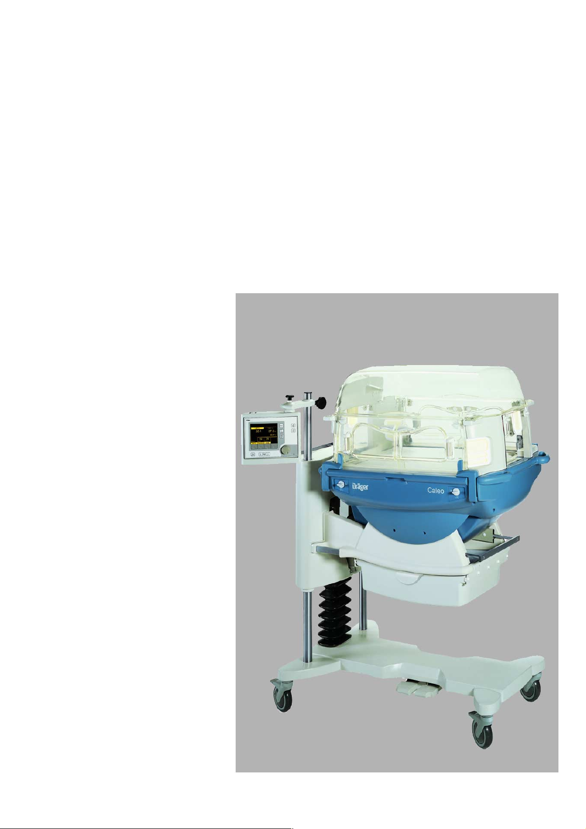
Caleo
Neonatal incubator
Instructions for Use
Software 1.n
®
255 29 515
1
How to use the Instructions for Use
The headline ...
specifies the subject of the main chapter
to help you find your way around rapidly.
The page ...
contains instructions for use of the unit
in a combination of text and illustrations. The information is
translated directly into practical actions showing the user
how to use the unit.
The left-hand column ...
contains text
explaining the unit and guiding the user clearly to its uses
through concise instructions in ergonomic sequence.
Dots refer to actions,
●
Numbers refer to the illustration next to the text and to the
sequence of actions in the case of operations consisting of
several steps.
The right-hand column ...
contains illustrations
as a reference to the text and to guide the user in handling the
unit itself. The elements mentioned in the text are highlighted,
and unnecessary details are omitted. The user is guided by
screens confirming the various steps required for each action.
Preparation
Before using for the first time
Preparation
Before using for the first time
● Check that all packaging materials have been completely
removed (see packing slip in the pack).
● Check that the mains power supply voltage matches the
voltage rating specified on the nameplate (see page 123).
● Check that the altitude above sea level is correctly set
(see page 73).
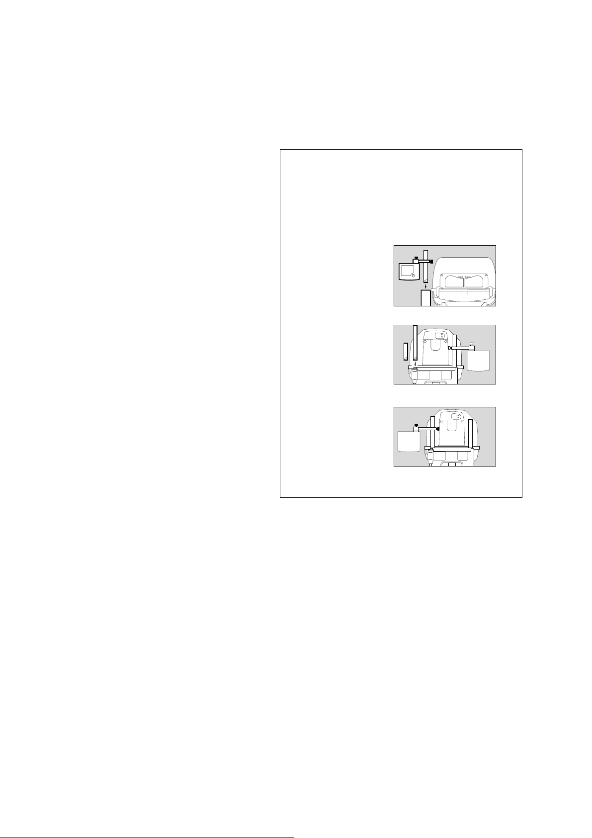
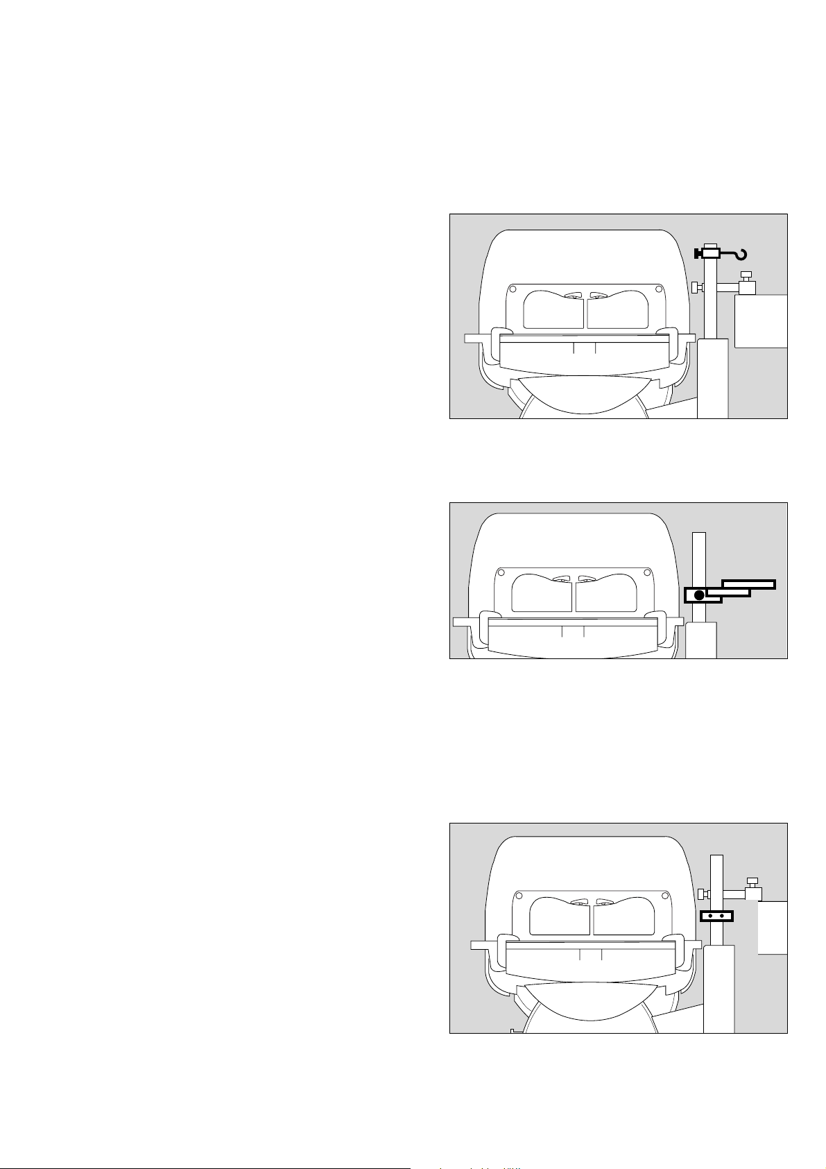
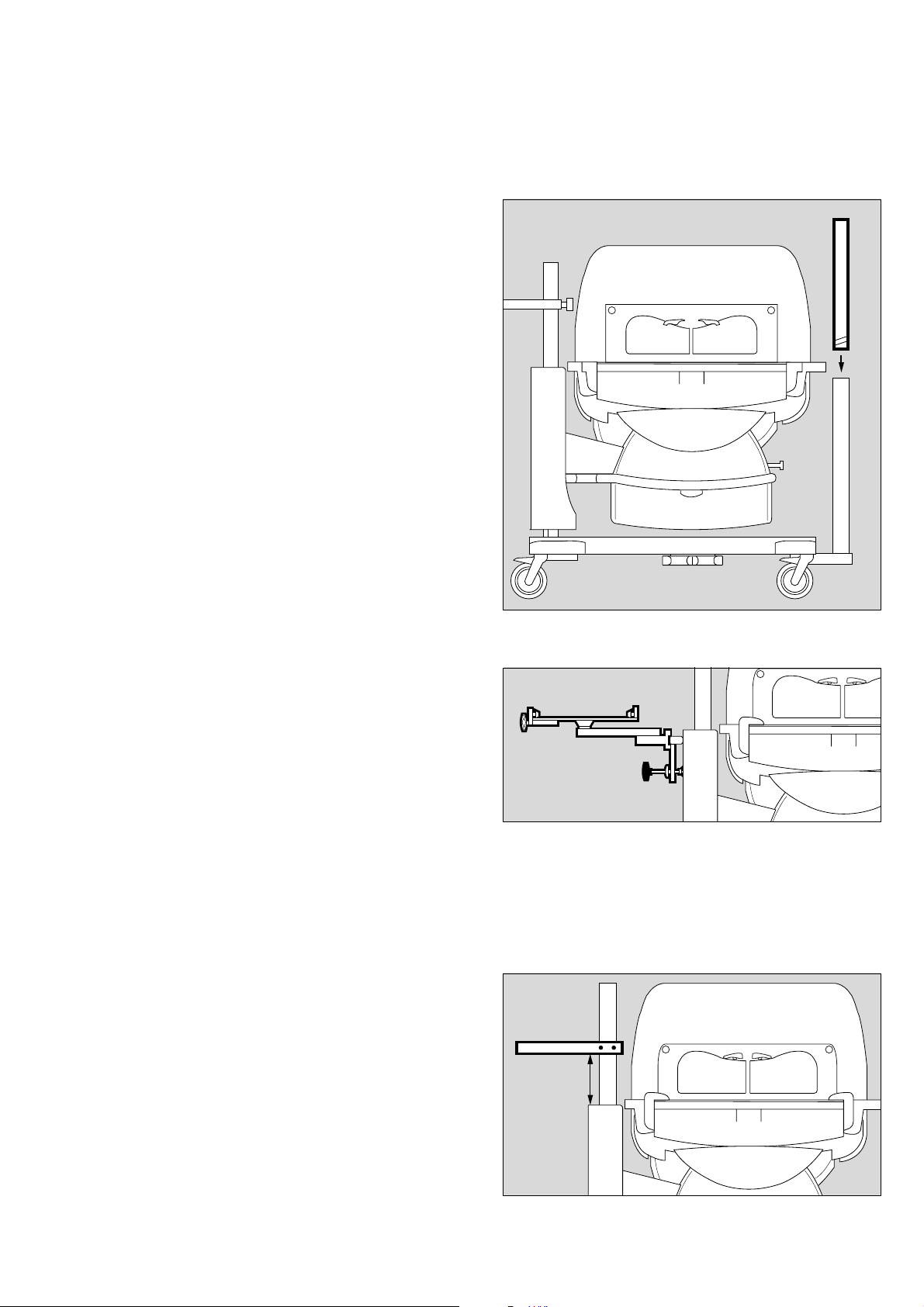
1 Screw the extension pole fully into the base frame and
tighten firmly. Check that it is securely held in place.
2 Slide the holder over the pole and secure it at the required
working height with the clamping screw.
3 Set the control unit to the desired working position and
clamp it securely to the holder with the locking screw.
Make sure that there is sufficient space to swivel and tilt
the control unit!
Fitting accessories
Screw in:
Pole 38 mm/600 (2M 50 691) or alternatively
Pole 38 mm/310 (2M 50 688)
● Remove the cover plate from the base frame.
● Screw the pole fully into the base frame and tighten firmly.
Check that it is securely held in position.
Moving the control unit to the opposite side
4 Remove the control unit = loosen the clamping screw.
5 Remove the holder = loosen the clamping screw.
● Move the holder to the other pole and set to the desired
working height.
5 Fix the holder in position = tighten the clamping screw.
4 Secure the control unit to the holder = tighten the clamping
screw.
12
3
2
1
116 2 9 51 5
228 29 515024 29 515
4
5
14737054
2

Contents
Contents
For Your Safety and that of Your Patients 4
Intended use 5
What's what 7
Operating concept 9
Preparation 11
Checking readiness for operation 26
Operation 33
Care 83
Maintenance intervals 94
Troubleshooting – Error Messages 97
Troubleshooting – Faults 102
Technical Data 103
Description 109
Order list 125
Parts List 128
Index 129
3

For Your Safety and that of Your Patients
For Your Safety and that of Your
Patients
Strictly follow the Instructions for Use
Any use of the apparatus requires full understanding and strict
observation of these instructions. The apparatus is only to be
used for purposes specified here.
Maintenance
The apparatus must be inspected and serviced regularly by
trained service personnel at six monthly intervals.
Repair and general overhaul of the apparatus may only be
carried out by trained service personnel. We recommend that
a service contract be obtained with DrägerService and that all
repairs also be carried out by them.
Only authentic Dräger spare parts may be used for
maintenance.
Observe chapter "Maintenance Intervals".
Accessories
Do not use accessory parts other than those in the order list.
Not for use in areas of explosion hazard
This apparatus is neither approved nor certified for use in
areas where combustible or explosive gas mixtures are likely to
occur.
Safe connection with other electrical equipment
Electrical connections to equipment which is not listed in
these Instructions for Use should only be made following
consultations with the respective manufacturers or an expert.
Liability for proper function or damage
The liability for the proper function of the apparatus is
irrevocably transferred to the owner or operator to the extent
that the apparatus is serviced or repaired by personnel not
employed or authorized by DrägerService or if the apparatus is
used in a manner not conforming to its intended use.
Dräger cannot be held responsible for damage caused by
non-compliance with the recommendations given above.
The warranty and liability provisions of the terms of sale and
delivery of Dräger are likewise not modified by the
recommendations given above.
Dräger Medical AG & Co. KGaA
4

Intended use
Therapy system providing a controlled supply of warmth,
humidity* and O
premature babies and sick neonates up to a body weight of
5 kg or a body length of 55 cm (when treating twins, the total
body weight is limited to 5 kg).
Used in
clinical environment, where premature babies or neonates
need controlled climate parameters.
The unit may only be used by properly trained personnel under
the supervision of qualified medical staff familiar with the
currently known risks and benefits of using an incubator.
2
enrichment* in the patient capsule for
Intended use
Possibilities for nursing and therapy
— Heat therapy through control of air temperature or skin
temperature
— Humidification
—O
2
therapy through controlled O
2
enrichment
— Normal or intensive care via hand ports or a large front flap
— Bed with pivoting adjustment for raising and lowering the
head
With monitoring for
— Air temperature
— Skin temperature
— Relative humidity
—O
2
concentration
— Weight*
* optional equipment feature
5

6

What's what
What's what
Contents
What's what . . . . . . . . . . . . . . . . . . . . . . . . . . . . . . . . . . . . . . . . . . . . . . . . . . . . . . . . . . . . 8
Front view . . . . . . . . . . . . . . . . . . . . . . . . . . . . . . . . . . . . . . . . . . . . . . . . . . . . . . . . . . . . . . 8
Side view, connections . . . . . . . . . . . . . . . . . . . . . . . . . . . . . . . . . . . . . . . . . . . . . . . . . . 8
Top view, bed . . . . . . . . . . . . . . . . . . . . . . . . . . . . . . . . . . . . . . . . . . . . . . . . . . . . . . . . . . 9
Operating concept . . . . . . . . . . . . . . . . . . . . . . . . . . . . . . . . . . . . . . . . . . . . . . . . . . . . . . 9
Control unit . . . . . . . . . . . . . . . . . . . . . . . . . . . . . . . . . . . . . . . . . . . . . . . . . . . . . . . . . . . . 9
Screen . . . . . . . . . . . . . . . . . . . . . . . . . . . . . . . . . . . . . . . . . . . . . . . . . . . . . . . . . . . . . . . 10
7
What's what
What's what
Front view
Canopy
Hand port
Front flap
Handle for transport
Housing
Drawer (2M 50 565)
Castors
Pedals for height adjustment
Height adjustable pillar
Connection for water heater (LuerLock)
X-ray drawer / removable bed
Display
Control unit
Pillar element
*
*
*
/ Housing support
1
2
3
4
5
6
7
8
9
10
11
12
13
14
15
16
17
18
19
20
21
22
23
24
25
13
12
*
11
10
9
14
1
2
3
4
5
6
Side view, connections
Central alarm indicator
Sensor unit, temperature connections
Mains power connection
On/off switch
Fresh air filter (MX 17 015)
Connection for O
Water container (2M 50 040)
Tubing grommet (2M 50 385)
Side flap
Tubing port (2M 50 412)
Feeding grommet, hood (2M 50 352)
2
for adjustment
7
88
111 2 9 51 5
152524
16
*
*
23
22
17
21
18
20
19
* optional equipment feature
8
112 2 9 51 5
Top view, bed
1
2
: 3
4
5
6
Operating concept
7
8
9
10
12
13
14
15
Spirit levels
Hot air duct
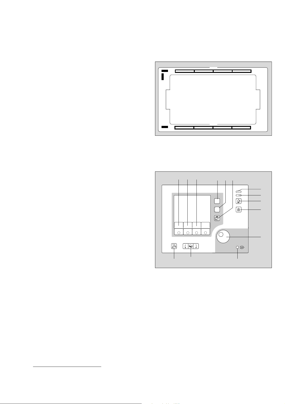
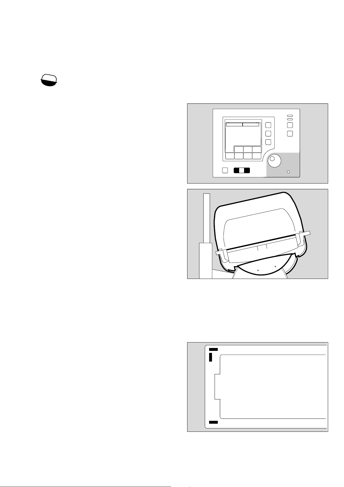
Operating concept
Control unit
Hard Keys
these permanently defined keys enable the user to select
various functions of Caleo
Scales
*
Bed tilt
Menu selection/configuration
Changeover key: air/skin temperature control
Trend display
Suppress alarm tone
Lock key pad function
Rotary knob
®
1
1
1
D
14
15 16
2
2
223 29 515
5
6 7
11
12
Menu
Air
Skin
8
9
Visual signals indicate alarm situations
11 Red alarm LED
Yellow alarm LED
Power failure alarm
Soft Keys
These keys, with variable functions defined by different labels
on the screen, guide the user through the specific routines of
the unit, from preparing for use to shutting down the unit.
Depending on the current menu, different soft keys with
varying functions and labels are activated.
Only the soft keys required for the current menu actually
appear. This precaution keeps the display clear, preventing any
confusion for the user.
When a soft key is pressed, its function is activated and the
relevant menu is displayed on the screen.
In the standard screen, the soft key labels are as follows:
Air/skin temperature
Humidity
16 O2
* optional equipment feature
*
*
10
3
4
13
040 29 515
9
Operating concept
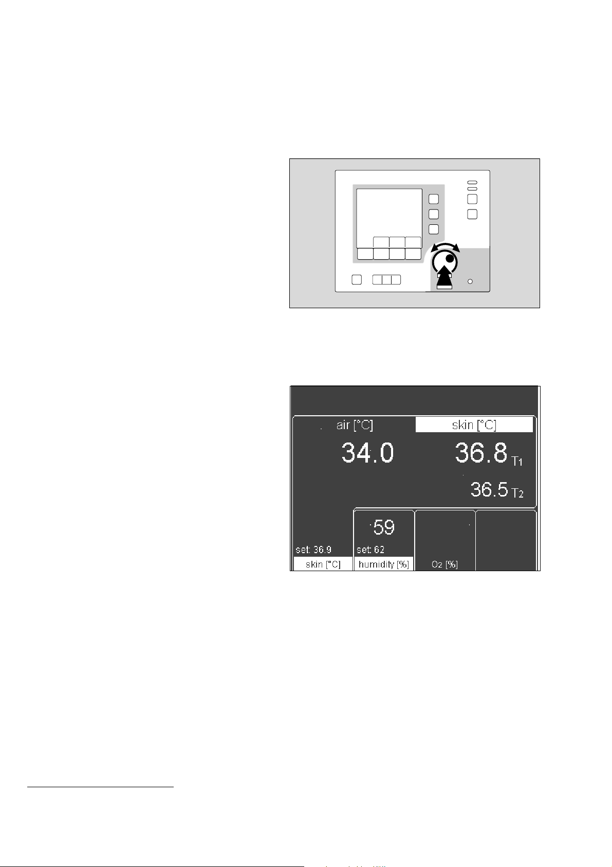
Rotary knob
A single rotary knob is used to select and set parameters.
● Turn knob = select
● Press knob = confirm
D
193 2 9 515
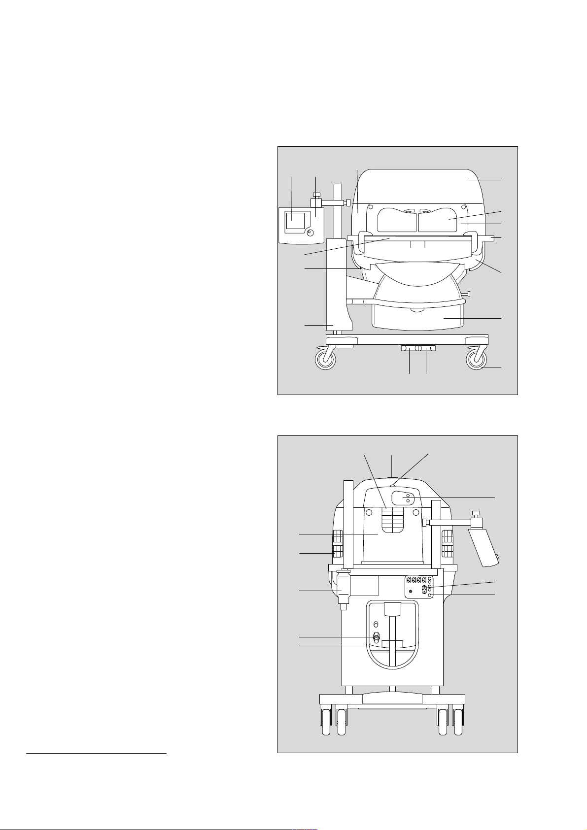
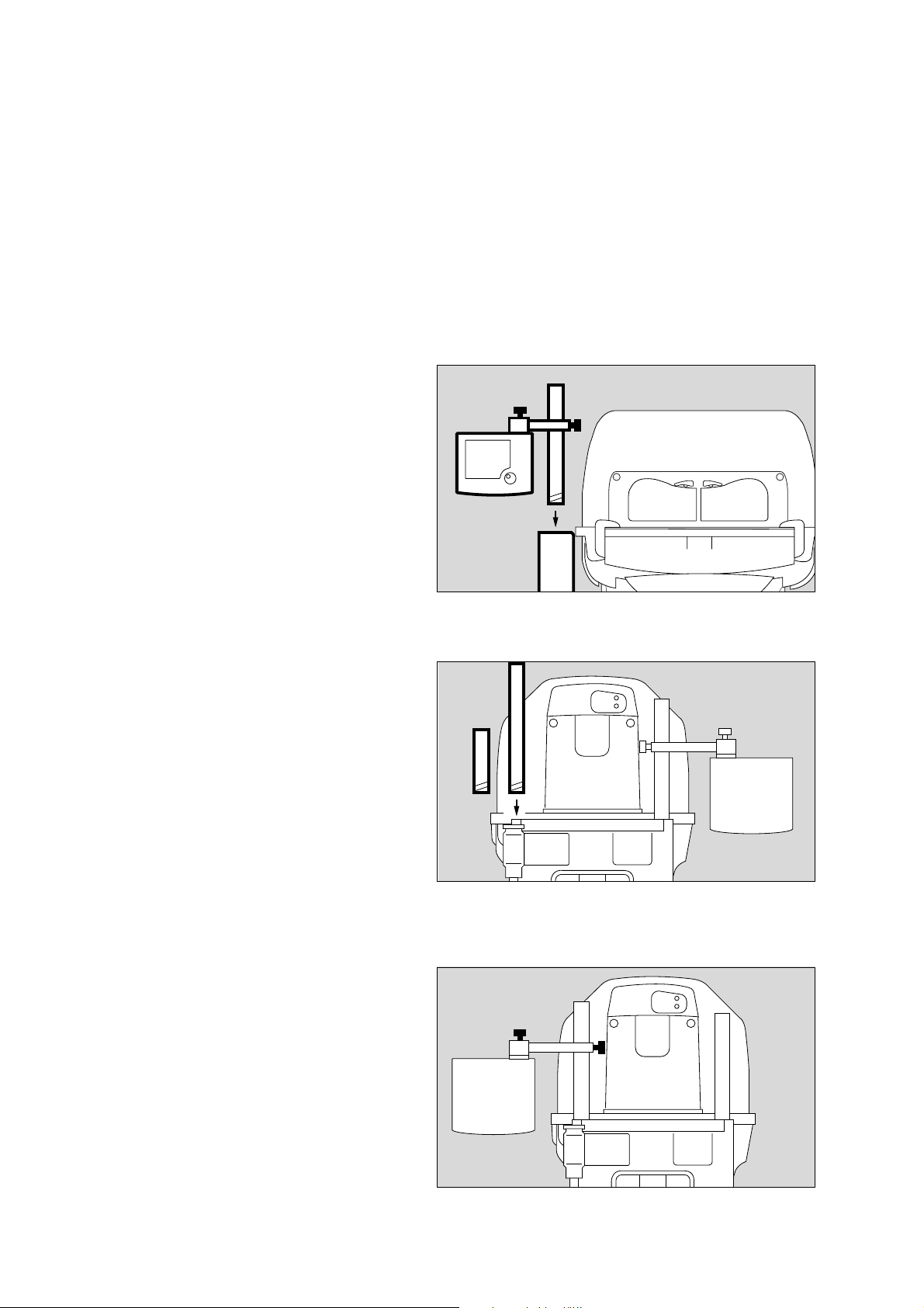
Screen
By default, the measured values are displayed as numeric
values (standard screen).
— Set values and actual measured
values for air temperature/skin temperature
— Set values and actual measured values for relative humidity
— Set values and actual measured values for
O2 concentration
— Alarms and warnings
The screen display can also include a trend graph.
*
*
000 37 054
* optional equipment feature
10

Preparation
Preparation
Contents
Preparation . . . . . . . . . . . . . . . . . . . . . . . . . . . . . . . . . . . . . . . . . . . . . . . . . . . . . . . . . . . 12
Before using for the first time . . . . . . . . . . . . . . . . . . . . . . . . . . . . . . . . . . . . . . . . . . . . 12
Fitting accessories . . . . . . . . . . . . . . . . . . . . . . . . . . . . . . . . . . . . . . . . . . . . . . . . . . . . . 12
Doors, ports and bed . . . . . . . . . . . . . . . . . . . . . . . . . . . . . . . . . . . . . . . . . . . . . . . . . . . 18
Checking readiness for operation . . . . . . . . . . . . . . . . . . . . . . . . . . . . . . . . . . . . . . . . 26
Before using for the first time . . . . . . . . . . . . . . . . . . . . . . . . . . . . . . . . . . . . . . . . . . . . 26
Before each use . . . . . . . . . . . . . . . . . . . . . . . . . . . . . . . . . . . . . . . . . . . . . . . . . . . . . . . 26
11
Preparation
Before using for the first time
Preparation
Before using for the first time
● Check that all packaging materials have been completely
removed (see packing slip in the pack).
● Check that the mains power supply voltage matches the
voltage rating specified on the nameplate (see page 123).
● Check that the altitude above sea level is correctly set
(see page 73).
1 Screw the extension pole fully into the base frame and
tighten firmly. Check that it is securely held in place.
2 Slide the holder over the pole and secure it at the required
working height with the clamping screw.
3 Set the control unit to the desired working position and
clamp it securely to the holder with the locking screw.
Make sure that there is sufficient space to swivel and tilt
the control unit!
3
2
1
Fitting accessories
Screw in:
Pole 38 mm/600 (2M 50 691) or alternatively
Pole 38 mm/310 (2M 50 688)
● Remove the cover plate from the base frame.
● Screw the pole fully into the base frame and tighten firmly.
Check that it is securely held in position.
Moving the control unit to the opposite side
4 Remove the control unit = loosen the clamping screw.
5 Remove the holder = loosen the clamping screw.
● Move the holder to the other pole and set to the desired
working height.
5 Fix the holder in position = tighten the clamping screw.
4 Secure the control unit to the holder = tighten the clamping
screw.
116 2 9 5 15
228 29 515024 29 515
4
5
12
Infusion support (2M 21 514)
for pole, 38 mm
● Place the fixing clamp on the stand pillar.
● Push the infusion support into the clip and secure by
tightening the clamping screw.
Preparation
Fitting accessories
010 2 9 515020 29 515101 29 515
Swivel table (2M 21 186)
For small articles, max. load 3 kg, for mounting on 38 mm pole
● Place the clamp of the swivel table on the stand pillar and
tighten the clamping screw.
Make sure that the table has space to swivel freely!
Compact rail (2M 85 337)
Max. load 5 kg, for mounting on 38 mm pole
This rail must only be mounted by qualified technical staff!
For holding accessories, e.g.
—O2 monitor
● Adjust the height of the compact rail to the required height
of the mounted accessory.
1 Fit the compact rail to the pole = push the compact rail over
the pole and
2 fasten with the screws.
1
2
13
Preparation
Fitting accessories
Bronchial aspiration system (2M 85 125)
Follow the separate Instructions for Use of the bronchial
aspirator.
● Fix the bronchial aspirator holder to the standard rail on the
wall side or handle side.
● Tighten the clamping lever.
● Establish the hose connections.
Basic pole (2M 50 680)
Maximum load 5 kg
This pole must only be mounted by qualified technical
staff!
For fixing accessories, e.g.
— additional pole extensions (see page 15).
— swivel table (2M 21 186)
— monitor support plate (2M 50 085)
● Fix to the unit in accordance with the separate Assembly
Instructions.
Tray 3020 (M 24 678)
Maximum load must not exceed 2 kg!
230 29 515
019 29 515021 29 515
● Hang the tray from the standard rail on the wall or handle
side and secure in position.
14
Pole extensions
The following poles can be fixed to the base pole as extension:
— Pole 38 mm/600 (2M 50 691) or
— Pole 38 mm/310 (2M 50 688) or
— Pole 25 mm/600 (2M 50 689).
● Screw the pole into the base pole as far as it will go and
tighten securely. Make sure that it is securely held in place.
Preparation
Fitting accessories
Notebook holder (2M 22 171)
Maximum load must not exceed 3 kg!
1 Fix the holder to the handle rail of the Caleo®.
2 Align the holder horizontally with the clamping screw.
● Check that the holder is securely fixed in position and that
the swivelling mechanism is functioning correctly by turning
and tilting the support plate.
Monitor shelf (2M 50 085)
Maximum load must not exceed 20 kg!
Shelf for monitor and ventilation equipment.
This shelf must only be mounted by qualified technical
staff!
To fix the monitor shelf, fit a second 38 mm pole
(see page 12).
● Fit the monitor holder = slide the plate over both 38 mm
poles and
3 fix in position with the screws.
The distance between the monitor shelf and the base
frame must not exceed 20 cm.
max. 20 cm
229 29 515022 29 515
1
2
3
15
023 29 515
Preparation
Fitting accessories
Hose holder for ventilation hoses (84 11 075)
● Open the front flap.
● Raise the bed and pull it out of the incubator.
● Push the mattress slightly to one side.
● Place the hose holder in the mounting hole in the bed and
fasten from underneath with the locking screw.
● Replace the bed in the incubator and close the front flap.
The hose holder can be fixed to any of the four corners of the
bed.
1 Clip the ventilation hoses and cables into the clips at the
end of the ventilation hose holder.
11
O2 enrichment with O2 control
*
2 Screw the O2 connecting hose into the port underneath the
incubator.
● Connect the probe to the outlet of the central O2 supply
pipeline in the "park" position (see separate Instructions for
Use).
The maximum gas pressure must be 500 kPa.
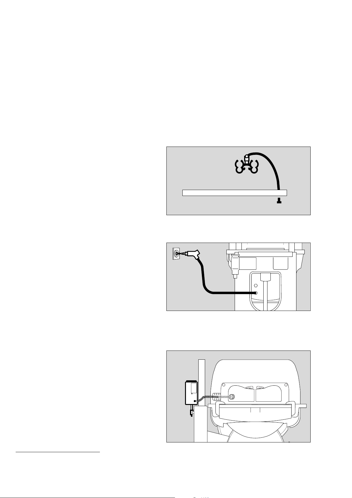
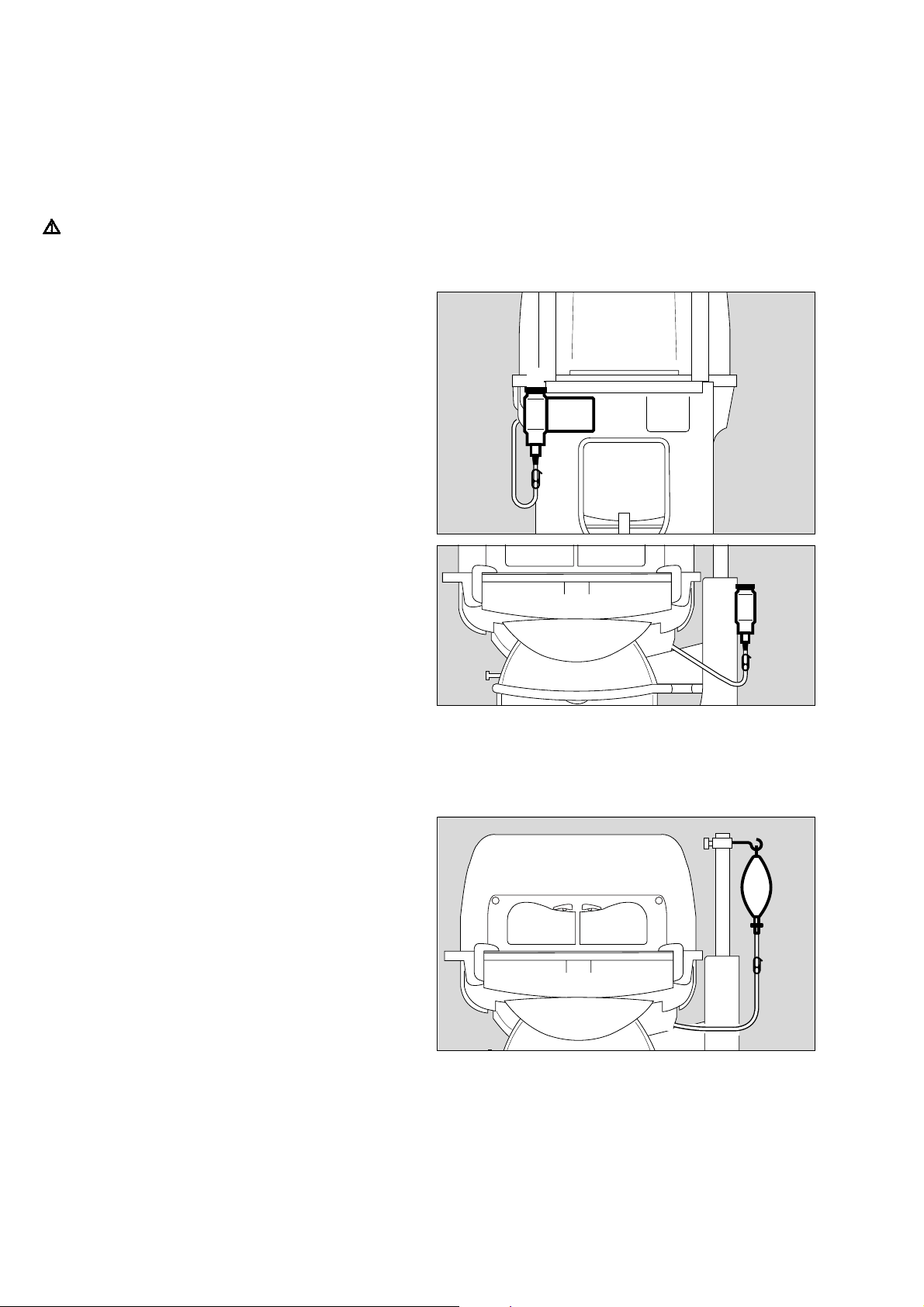
O2 monitor
To monitor the O2 concentration, use an O2 monitor that has
alarm limits:
● Fix the O2 monitor to the handle rail with the holder.
● Place the sensor capsule in Caleo
● Route the sensor cable through one of the flexible tubing
®
.
ports. Where applicable, push the sensor plug into the
socket of the O2 monitor (e.g. Oxydig or MiniOx) until it
audibly clicks into place (see separate Instructions for Use
2 monitor).
of O
008 29 515
2
011 29 515
* optional equipment feature
16
028 29 515
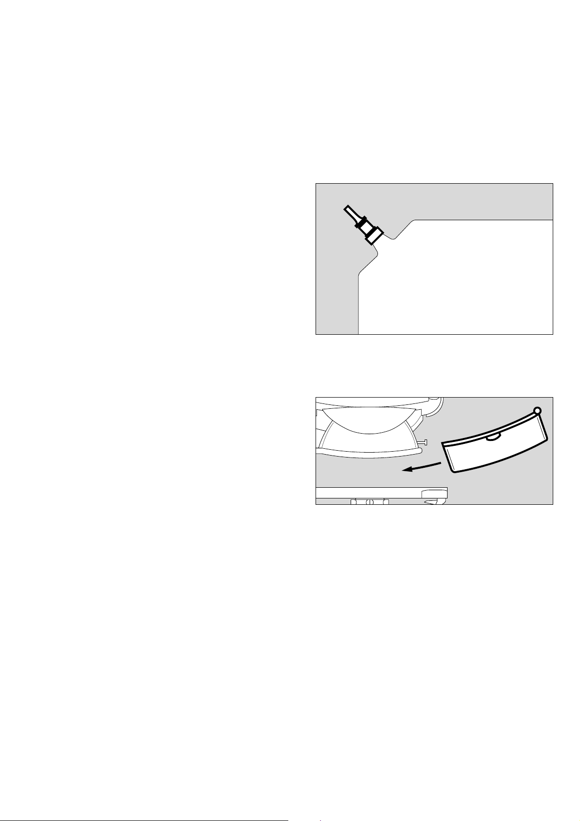
Vacuum mattress (2M 17 909)
The contour of the vacuum mattress can be altered as required
and is then maintained after air evacuation of the mattress.
Extreme positions can therefore be obtained for special
applications. The foam mattress can remain in the incubator.
● Open the front flap.
● Insert and preform the vacuum mattress.
● Place the patient on the mattress and finally adjust the
mattress to the desired shape.
● Connect the vacuum mattress to the hose of the suction
system.
1 Open the valve and evacuate the vacuum mattress.
1 Close the valve and disconnect the hose.
● Close the front flap.
Preparation
Fitting accessories
1
Fitting the drawer (2M 50 565)
Maximum load must not exceed 7 kg.
● Fit the drawer = slide the drawer box into the groove in the
base frame.
213 2 9 515
118 29 515
17
Preparation
Doors, ports and bed
Doors, ports and bed
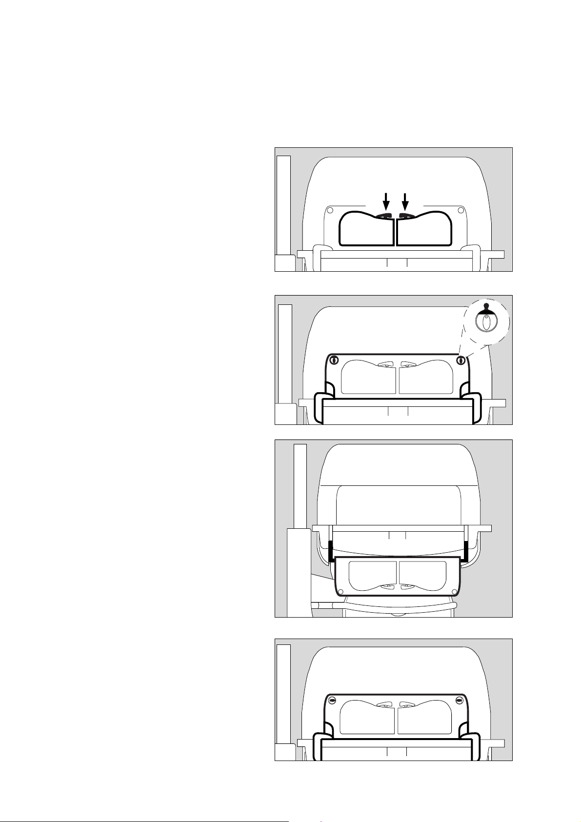
Hand ports
To open the hand ports:
1 Press the catch: the relevant hand port swings open.
To close the hand ports:
● Push the hand ports back into place until the catch
engages.
Front flap
To open the front flap:
2 Turn the two knobs inwards to the vertical position.
The red latch becomes visible.
11
014 29 529
● Lower the front flap until it hangs down vertically towards
the floor.
Avoid pinching or jamming hoses and cables in the removable
double wall!
To close the front flap:
● Raise the front flap and press into position,
3 Turn the two knobs outwards to the horizontal position until
you feel them click into place.
2
2
015 2 9 515
016 2 9 515091 29 515
Make sure that both knobs are engaged in position!
The red latches must no longer be visible!
18
3
3
Side flap
● The side flap is opened and closed in the same way as the
front flap (see page 18).
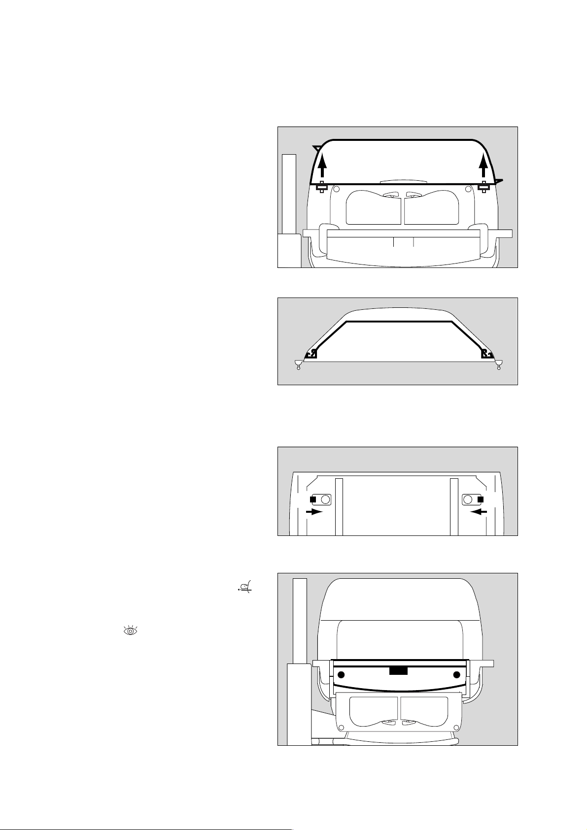
Canopy
To open the canopy:
1 Grasp the handle on the canopy
and
2 lift open (approx. 60o).
Preparation
Doors, ports and bed
231 29 515104 2 9 515
2
Do not tilt the canopy forwards!
3 Raise the side support prop, and lower the canopy until the
prop is fixed in the slot of the canopy.
To close the canopy:
1 Grasp the handle on the canopy and raise it slightly.
3 Fold down the prop
and
● close the canopy.
The canopy can be opened from both sides.
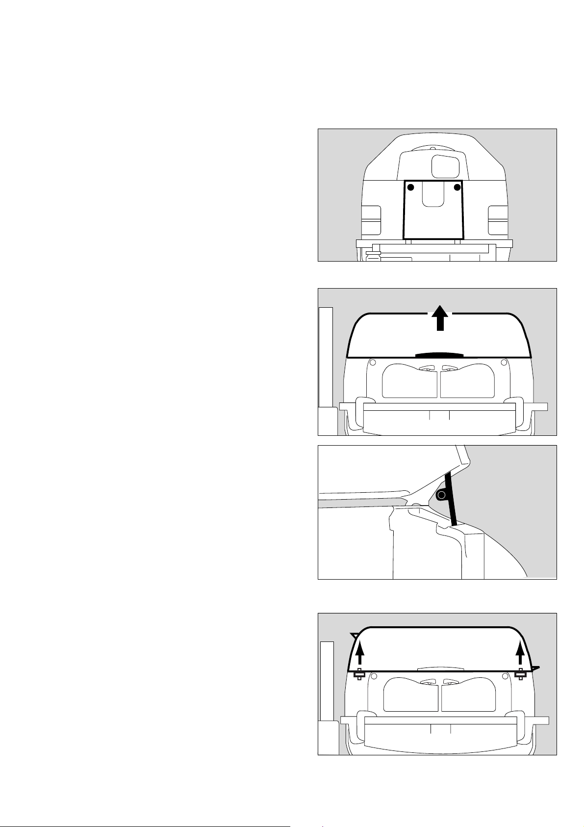
To remove the canopy:
4 Grasp the handles on the sides of the canopy with both
hands.
5 Lift the canopy horizontally off the pillar elements.
1
3
196 2 9 515
4
To replace the canopy:
5 Replace the canopy horizontally, so that the guide pins fit
into the holes in the pillar element.
Take care with the sensor unit!
4
55
093 29 515
19
Preparation
Doors, ports and bed
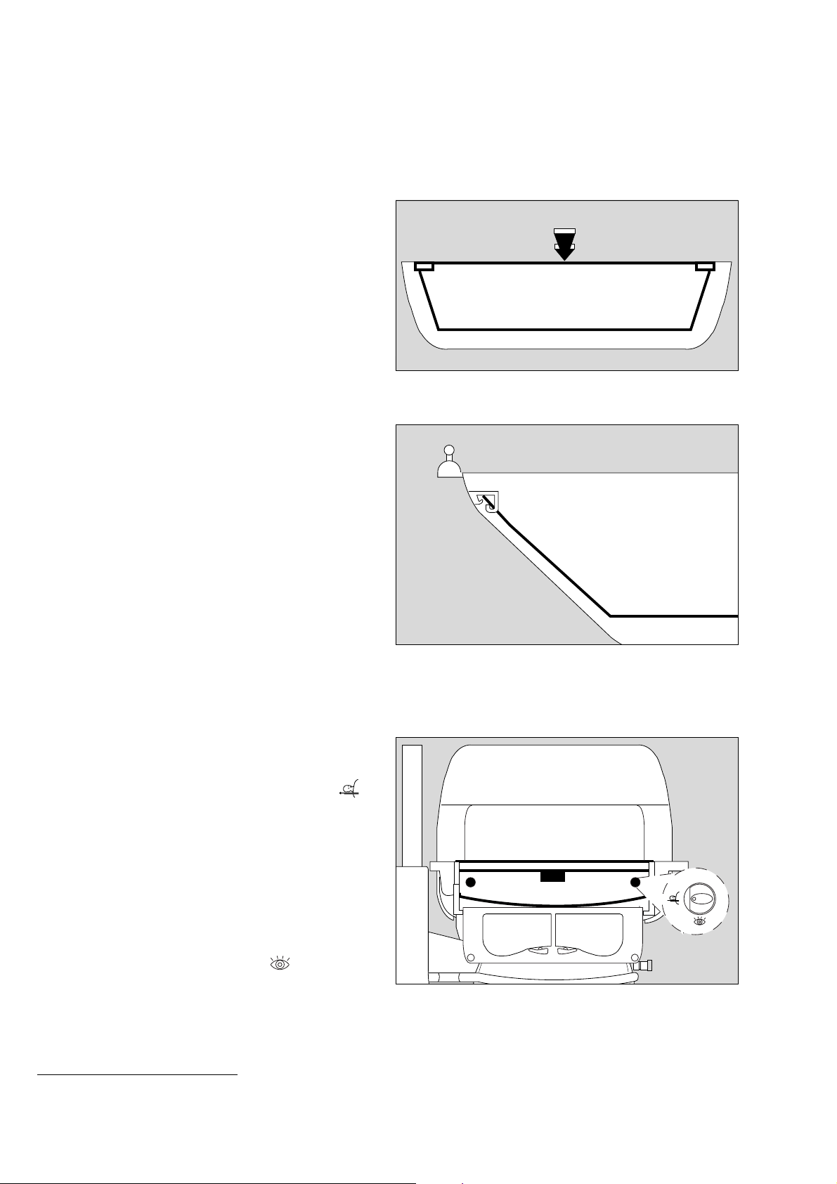
Double wall
*
To remove the double wall:
● Remove the canopy and lay it upside down (on a soft,
non-abrasive surface).
1 Squeeze the double wall inwards slightly, and
2 release the oblong holes of the double wall from the
retaining lugs in the canopy.
● Pull the double wall out of the canopy.
To install the double wall:
● Place the canopy upside down (on a soft, non-abrasive
surface).
● Insert the double wall in the canopy.
3 On one longitudinal side, fit the retaining lugs of the canopy
into the oblong holes of the double wall.
● Squeeze the double wall inwards slightly and fit the
retaining lugs on the second longitudinal side of the canopy
into the oblong holes of the double wall.
● Turn the canopy the right way up again.
The retaining lugs of the canopy must remain seated in the
oblong holes.
2
2
1
149 29 515
3
Removing the bed
Maximum load must not exceed 5 kg
● Open the front flap and fold it down.
Pull the bed out:
4 Set both knobs horizontally to the position marked ,
5 Pull the bed out towards the front as far as it will go, holding
it by the recessed handle or by the knobs.
When the bed is pulled out, monitor the patient constantly
to prevent the risk of a fall.
Do not lean or rest any weight on the bed when it is pulled
out.
● After completing the care procedure, push the bed back in
until it engages. Turn the knobs to the position and
close the front flap.
Push the bed all the way in! Otherwise the hot air duct will
be interrupted, and the patient may be warmed or cooled
excessively!
4 4
5
252 29 515
187 29 515
* optional equipment feature
20
Using the X-ray drawer
The X-ray drawer can be pulled out when the front flap is either
open or closed.
To open the X-ray drawer:
1 Set both knobs vertically to the position marked ,
2 pull the drawer out by the recessed handle or the knobs.
● Insert or remove the X-ray cassette. Recesses are provided
in the X-ray drawer for positioning.
Do not use the X-ray drawer as a writing support or bed for
the patient.
To close the X-ray drawer:
2 push the drawer inwards under the bed until it tangibly
clicks into place.
Push the X-ray drawer in fully! Otherwise the hot air duct
will be interrupted, and the patient may be warmed or
cooled excessively!
Preparation
Doors, ports and bed
1
2
1
017 29 515
Sealed through-holes
3 Tubing ports (2M 50 412)
4 Tubing grommets (2M 50 385)
5 Feeding grommet, hood (2M 50 352)
● Route the cables or hoses through the flexible grommets
and sleeves.
To route ventilation hoses and cables through the Caleo®, use
the ventilation hose holder (page 16).
Drawer (2M 50 565)
Drawer for storing items required for nursing or treatment.
The drawer is accessible from both sides.
Open the drawer:
6 grasp the drawer by the handle and pull it out as far as it
will go.
● Place the required material in the drawer.
5
3
44
095 29 515
Close the drawer:
6 push the drawer back in by the handle.
6
013 29 515
21
Preparation
Doors, ports and bed
Trolley (base frame) with variable height adjustment
*
To use the height adjustment facility:
● Switch on Caleo
®
(see page 37).
1 Press the left pedal – Caleo® is lowered.
2 Press the right pedal – Caleo® is raised.
● Adjust to a comfortable working height.
When the height stops changing, the frame is at its end
position. Release the pedal.
Hoses and cables must be long enough so that they do not
kink, tear or become squashed!
Do not store anything under the drawer!
The height adjustment and tilt angle adjustment cannot be
operated at the same time!
The height adjustment can only be operated for
max. 6 minutes during one hour.
1 2
009 29 515
* optional equipment feature
22
Tilting the bed
Preparation
Doors, ports and bed
To tilt the bed:
● Switch on Caleo
®
(see page 37).
1 Press button = raise the bed on the control unit side.
2 Press button = lower the bed on the control unit side.
● Adjust the bed to the required tilt angle.
The end position is reached when the tilt angle stops
changing. Release the button.
®
The entire housing of the Caleo
incubator is tilted.
Hoses and cables must be carefully routed so that they do
not kink, tear or become squashed!
The height adjustment and tilt angle adjustment cannot be
operated at the same time!
Do not reach in between the housing and housing support
during adjustment. Danger of injury!
D
1
2
214 29 515
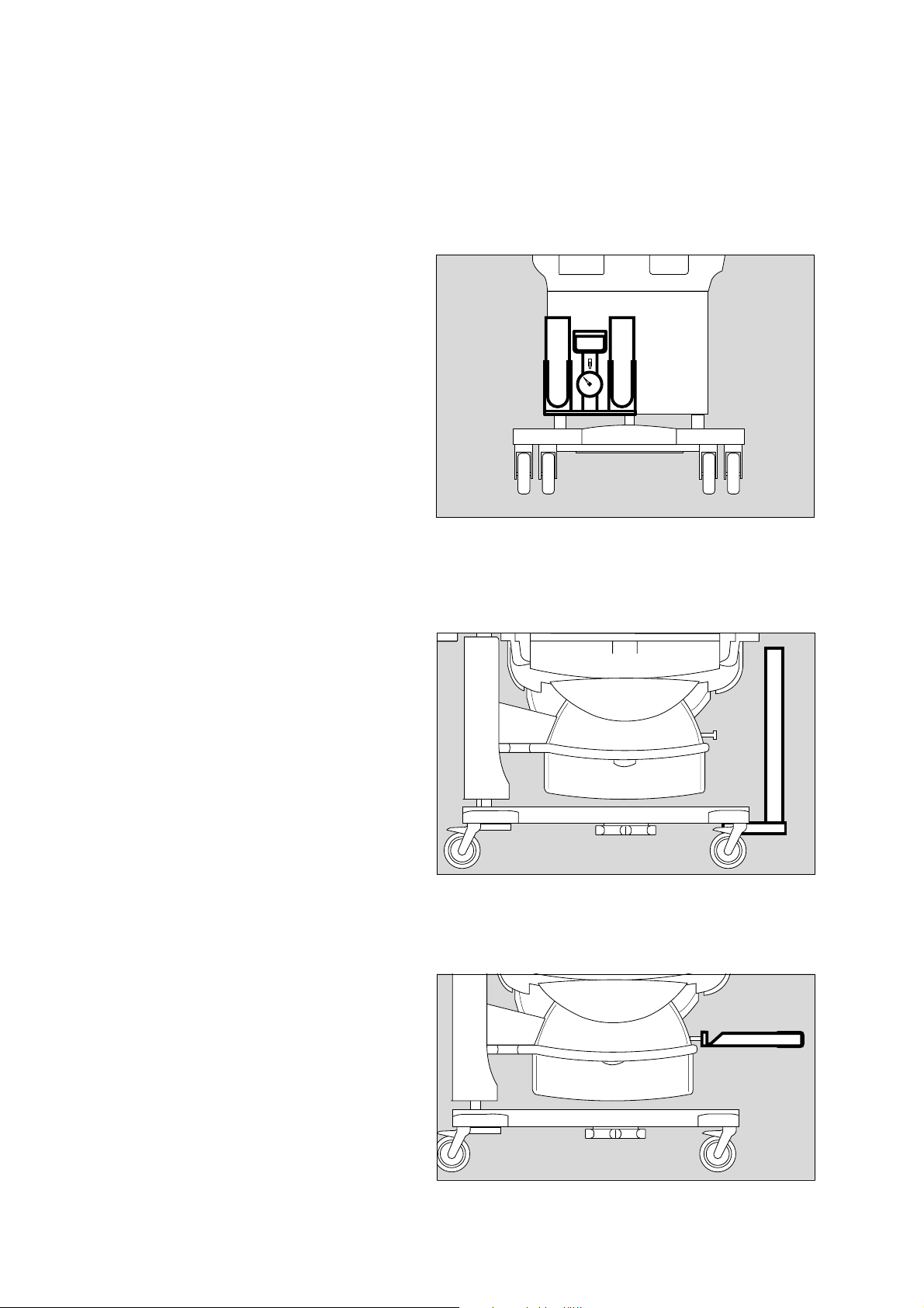
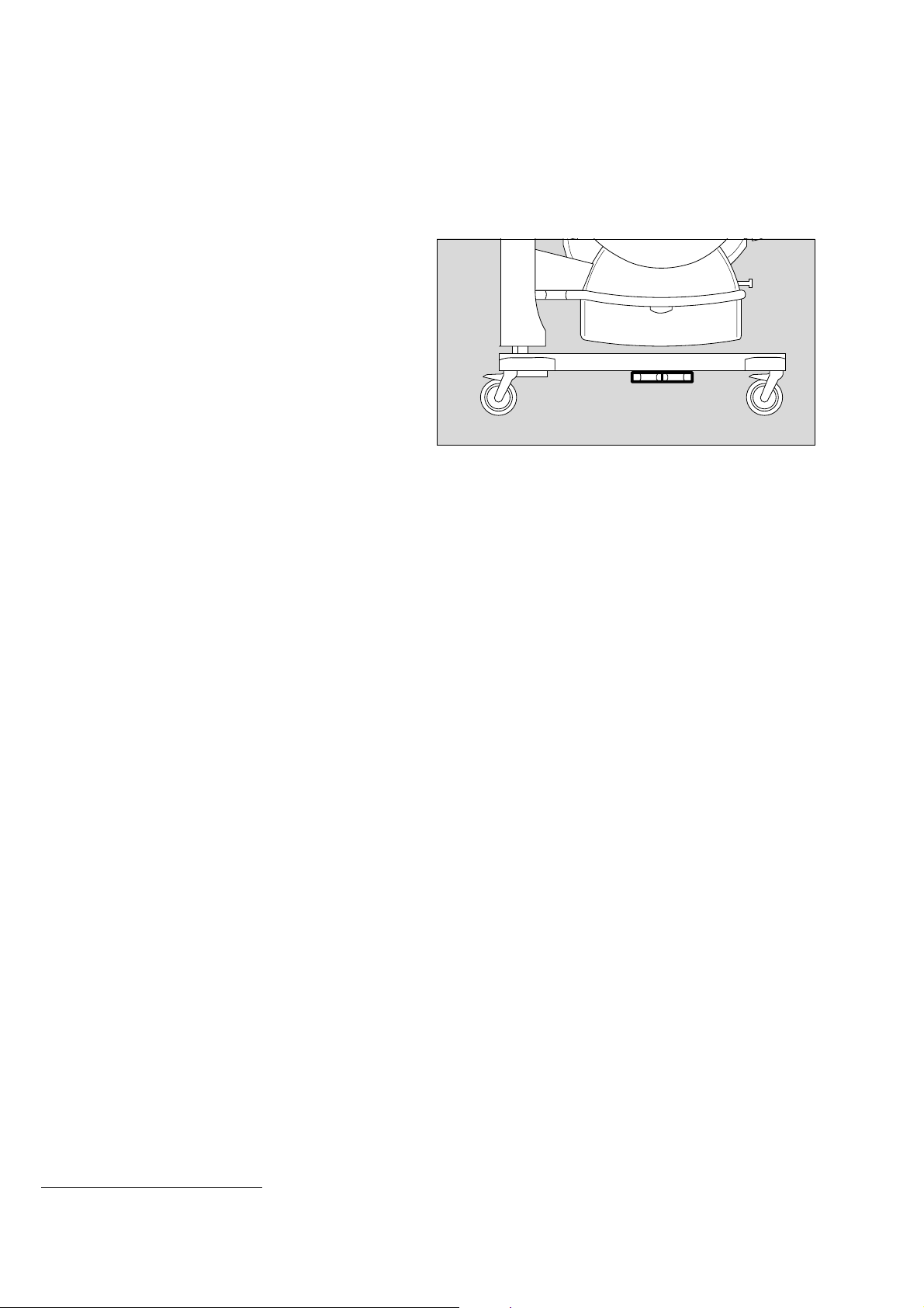
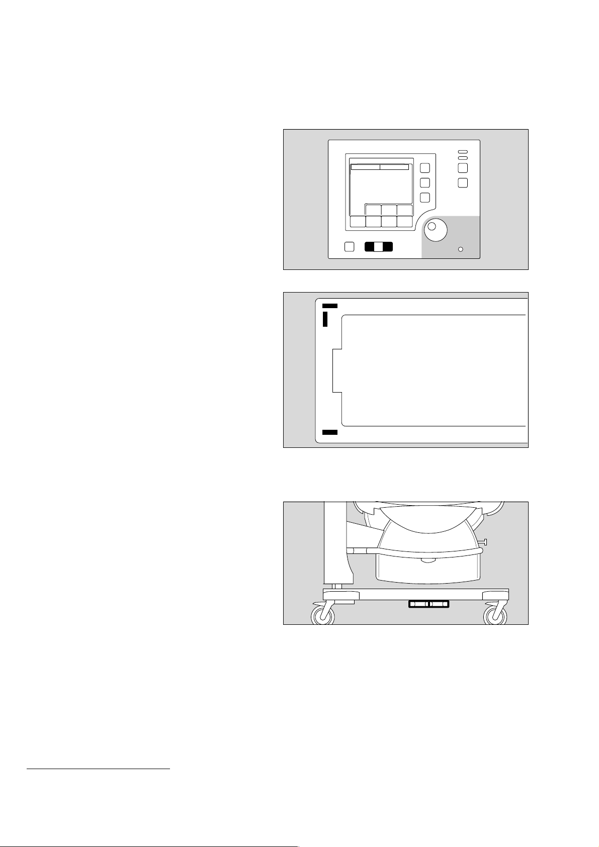
Setting the bed to the horizontal position
● Caleo
®
must be switched on (see page 37).
1 Press button = the bed will be raised on the control unit
side.
2 Press button = the bed will be lowered on the control unit
side.
The spirit levels show whether the bed is horizontal.
3 Spirit levels for the horizontal position of Caleo® in the
transverse axis.
®
4 Spirit level for the horizontal position of Caleo
in the
longitudinal axis. When using the integrated scales
(optional, see "Weighing scale" on page 78), make sure
that the unit is on a flat floor before setting.
086 29 515
3
4
3
242 2 9 515
23
Preparation
Doors, ports and bed
Using humidifier systems
Use only sterilised Aqua dest.!
Water container (2M 50 040):
● Disinfect hands.
1 Open the water container = lift up the cap.
● Fill the water container with sterilised Aqua dest.
Do not use any additives!
Capacity: 2.8 L (note level marks)
1 Close water container = push down the cap.
● Prepare a fresh connection tube (MX 17 018).
2 Close the clamp on the connection tube.
3 Pierce the silicone nozzle of the water container with the pin
of the connection tube.
2 Open the clamp on the connection tube.
● Bleed the connection tube (let distilled water drain off).
2 Close the clamp on the connection tube.
4 Connect the LuerLock connection to the water connection
pipe.
5 Open the clamp on the connection tube.
● Switch on the humidification module on Caleo
®
and set the
humidity value (page 51).
1
3
2
097 29 515
4
5
Water bag:
Use only sealed bags with sterilised Aqua dest.!
Do not use any additives!
Must not be confused with infusion solutions!
● Disinfect hands.
● Prepare a new connection tube (MX 17 018) and a water
bag with sterilised Aqua dest.
6 Close the clamp on the connection tube.
● Insert the pin of the connection tube into the connector of
the water bag.
6 Open the clamp on the connection tube.
● Bleed the connection tube (let distilled water drain off).
6 Close the clamp on the connection tube.
7 Connect the LuerLock connection to the water connection
pipe.
6 Open the clamp on the connection tube.
● Switch on the humidification module on Caleo
®
and set the
humidity value (page 51).
Replacing the water bag:
Distilled water bag empty = the water shortage alarm on
®
Caleo
is triggered.
● Disinfect hands.
● Close the clamp on the connection tube.
● Replace the water bag and reopen the clamp.
185 2 9 515
6
7
098 29 515
24
25
Preparation
Doors, ports and bed
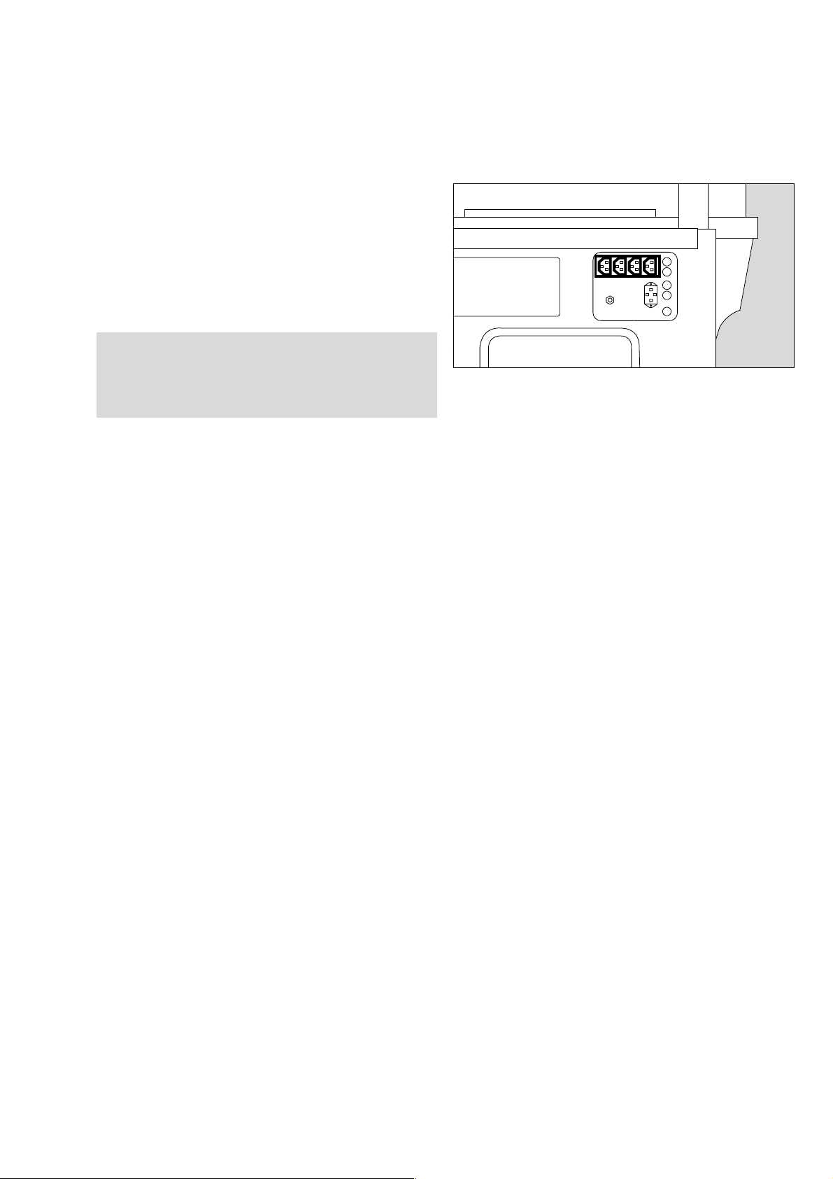
Integrated socket strip
The integrated socket strip can be used to connect
— infusion pumps and
— SpO
2
measuring equipment.
Connections may only be made by qualified technical staff.
Caleo does not monitor the power supply to external devices.
[
Do not exceed the maximum power input of the
connected accessories (all 4 sockets together: max. 2A).
The maximum permissible total leakage current must not
be exceeded. For the leakage current of Caleo
®
without
099 29 515
socket strip, see "Technical Data" on page 104.

Checking readiness for operation
Before using for the first time
Checking readiness for operation
Before using for the first time
● Check that the mains voltage supply corresponds to the
voltage rating on the nameplate (see page 123).
● Check that the altitude above sea level is correctly set
(see page 73).
Before each use
● Check that the equipment has been disinfected and
cleaned in accordance with the conditions laid down by the
hospital (see "Disinfecting/Cleaning/Sterilising" on
page 84).
● Check that an adequate gas supply is available for the
equipment to be used.
● Check that the required accessories and therapy
equipment are available and in perfect condition.
Only use parts that have been stripped down and sterilised.
Check readiness for operation in accordance with the
relevant Instructions for Use.
● Check that there are no cracks or sharp, chipped edges on
the incubator canopy.
● Check that the hinges and catches on the canopy are in
proper working order.
● Check that the cables and hoses have been routed
correctly and safely.
● Check that there is sufficient space for adjusting the tilt and
height.
● Connect to the mains supply.
● Check that the slits of the sensor unit are not fouled.
Do not use multiple-plug adapters for the Caleo® power
supply!
The patient leakage current may rise above the permitted
limits if the protective earth conductor fails when equipment
is connected to the socket strip. The risk of electric shocks
cannot be excluded in such cases.
Before using the unit, make sure that the following tests have
been performed:
Disinfect hands before each test!
Check that the hand ports are secure
1 Open hand port = press catch
● Close hand port until the catch engages.
● Pull the edge of the hand port – it must not open.
If the hand port fails to remain engaged:
● Call DrägerService.
11
014 29 529
26
Check that the front flap is secure
● Open the front flap and fold it down (see page 18).
1 Raise and press the flap closed and turn the two knobs
outwards until they tangibly engage in the horizontal
position.
Checking readiness for operation
Before each use
Make sure that both knobs are engaged!
The red latches must no longer be visible!
If the front flap fails to remain engaged or if the red latches are
visible:
● Call DrägerService.
Check that the side flap is secure
● Open the side flap and fold it down (see page 19).
2 Fold up the side flap and press it closed. Turn the two
knobs outwards until they tangibly engage in the horizontal
position.
Make sure that both knobs are engaged!
The red latches must no longer be visible.
If the side flap fails to remain engaged or if the red latches are
visible:
● Call DrägerService.
Check that the canopy is secure
3 Grasp the handle and open the canopy.
4 Lift open the flap (approx. 60o).
1
1
090 29 515
22
189 2 9 515
4
5 Raise the side prop.
● Lower the canopy until the prop is secured in the slot of the
canopy.
If the canopy fails to remain open:
● Call DrägerService.
3
224 29 515
5
225 29 515
27
Checking readiness for operation
Before each use
1 Grasp the handles on the sides of the canopy with both
hands.
2 Lift the canopy horizontally off the pillar elements.
1
If the canopy holders are damaged:
● Call DrägerService.
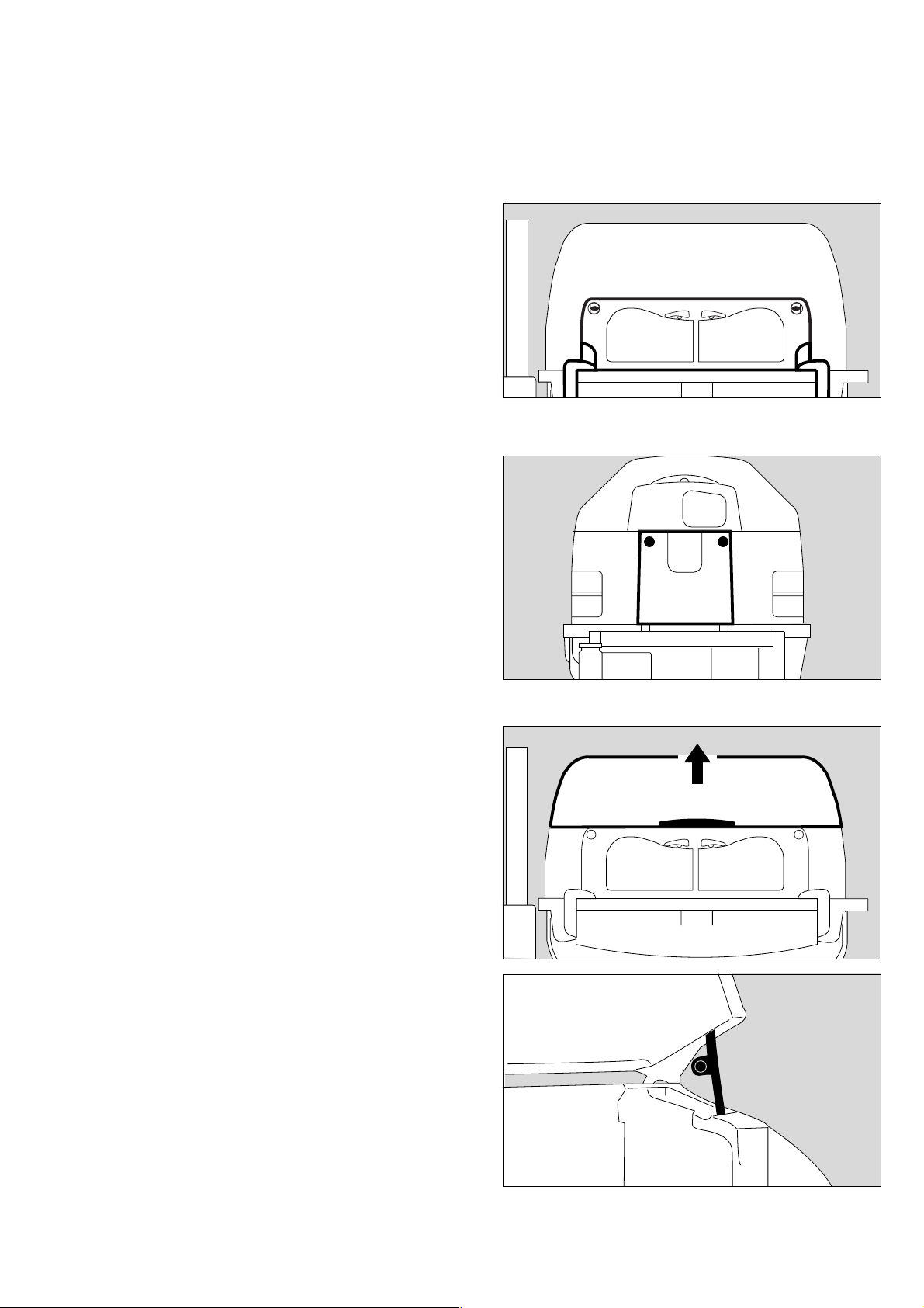
Check that the double wall is securely in place
● All 4 retaining lugs in the canopy must be seated in the
oblong holes of the double wall.
If the double wall or the retaining lugs in the canopy are
damaged:
● Call DrägerService.
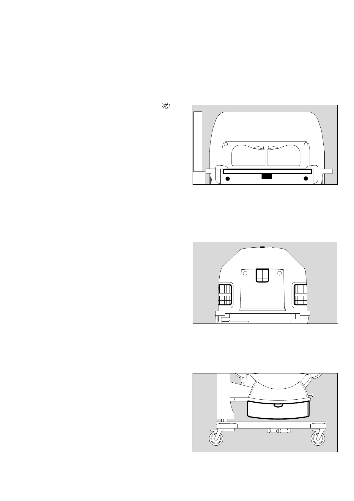
Check that the trough is secure
● Remove the canopy.
● Remove the mattress.
● Remove the bed.
3 Check the catches of the trough.
● Place the bed on the trough.
● Place the mattress on the bed.
● Refit the canopy.
1
22
226 29 515
135 2 9 515136 2 9 515
If the catches for the trough are damaged:
● Call DrägerService.
Remove the bed
● Open the front flap and fold it down.
4 Set both knobs horizontally to the position marked ,
5 Grasp the bed by the recessed handle or by the knobs and
pull it out towards the front as far as it will go.
5 Push the bed back until it clicks into place,
4 turn the knobs to the position.
● Close the front flap.
If the bed cannot be pulled out or pushed in or if the knobs are
damaged:
● Call DrägerService.
If the bed is not fully pushed in, the hot air duct will be
interrupted, causing the control system to malfunction!
The result may be excessive cooling or overheating of
the patient!
3
4
5
4
3
018 29 515
28
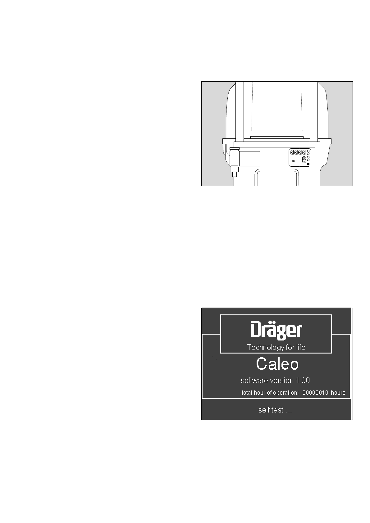
Activate the self-test, check audible warning tone
1 Switch on the unit = press the on/off switch until it clicks
into position.
Checking readiness for operation
Before each use
1
During the self-test, the functions of the machine are checked.
The audible signal, alarm beep sequence, screen displays and
LEDs must be checked by the user.
— An audible warning signal and an alarm beep sequence are
sounded.
If the warning signal or alarm beeps are not sounded,
● Call DrägerService.
— The screen and LEDs initially go dark and are then lit.
If individual pixels fail to light up or screen images are burnt, or
if the LEDs fail to light up,
● Call DrägerService.
— The opening screen is displayed.
If the opening screen is not displayed,
● Call DrägerService.
110 2 9 5 15
The unit is switched on.
04237054
29
Checking readiness for operation
Before each use
Check the bed tilting mechanism
1 Tilt the bed.
During the tilting process, the entire housing of the Caleo
must move uniformly. If not:
● Call DrägerService.
Do not reach in between the housing and the housing
support while the unit is moving! Risk of injury!
®
D
1
2
2 Return the bed to the horizontal position (see page 23).
● The spirit levels in the bed show whether the bed is
horizontal. This check is especially important when using
the built-in weighing scales (see page 78)!
If the spirit levels are damaged:
● Call DrägerService.
Check the height adjustment mechanism
● Operate both foot pedals in succession to raise and lower
*
the Caleo® (see page 22).
● Then adjust to a comfortable working height.
When adjusting the height, the entire housing of the Caleo®
must rise or descend uniformly. If not:
● Call DrägerService.
132 2 9 515
253 29 515
* optional equipment feature
30
089 29 515
 Loading...