

Page 1

D-Link DP-G310
Wireless G Print Server
Manual
Rev. 01 (February, 2008)
1
Page 2

Contents
Package Contents ..................................................................................................4
Contents of Package:..........................................................................................4
System Requirements:........................................................................................4
Introduction............................................................................................................1
External Features ...................................................................................................3
Port Connector....................................................................................................3
Rear Panel Connectors..........................................................................................4
Network Cable Connector.......................... .........................................................4
Antenna Connector............................................................................................. 5
USB Port Connector............................................................................................5
Reset Button.......................................................................................................5
DC Power Connector... .......................................................................................5
Front Panel .............................................................................................................6
LED Indicators ....................................................................................................6
Wireless Basics......................................................................................................7
Wireless Installation Considerations.................................................................... 9
Installing Consideratons......................................................................................9
Setting up the DP-G310........................................................................................10
Installing the Print Server..................................................................................10
Power ON Self-Test...........................................................................................11
Getting Started......................................................................................................13
Using PS-Wizard...................................................................................................14
Auto-Run Installation.........................................................................................14
PS-Wizard......................................................................................................... 15
Installing PS-Wizard..........................................................................................15
Using PS-Wizard...............................................................................................19
Using the Web Configuration..............................................................................25
Home.................................................................................................... ............25
SETUP > Print Server Setup.............................................................................27
SETUP > LAN Setup.........................................................................................29
SETUP > Wireless Setup..................................................................................30
SETUP > Printer Setup .....................................................................................31
ADVANCED > Advanced LAN...........................................................................40
2
Page 3

ADVANCED > Advanced Wireless....................................................................42
ADVANCED > User Access ..............................................................................43
ADVANCED > E-Mail Notification......................................................................45
ADVANCED > SNMP........................................................................................47
MAINTENANCE > Password............................................................................48
MAINTENANCE > Save/Restore Settings.........................................................49
MAINTENANCE > Firmware Upgrade ..............................................................50
MAINTENANCE > Diagnostics ......................................................................... 51
STATUS > Device Info ......................................................................................52
STATUS > Network...........................................................................................53
STATUS >Wireless............................................................................................55
STATUS >Print Log...........................................................................................56
HELP ................................................................................................................57
Reboot.................................................................. ................................ ............58
Refresh Printer Status.......................................................................................59
TCP/IP Printing for Windows Vista......................................................................60
TCP/IP Printing for Windows XP .................................................... .....................71
TCP/IP Printing for Windows 2000...................................................................... 85
TCP/IP Printing for Windows 98SE/ME.............................................................100
Unix/Linux Printing ............................................................................................114
Printing Text Files form Unix............................................................................114
Printing form BSD Unix Versions.....................................................................115
Printing from SCO Unix System V/386............................................................118
Printing from Solaris........................................................................................120
Printing from Red Hat Linux....................................................... .....................121
Setting up Printing in Mac OS X Tiger (10.4.9).................................................128
Adding a Printer..............................................................................................130
AppleTalk-enabled or Bonjour-enabled Printers..............................................133
Setting up AppleTalk Printing in Mac OS 9.......................................................143
Technical Specifications....................................................................................147
Appendix: DP-G310 Printer Compatibility List.................................................148
3
Page 4
Package Contents
Contents of Package:
D-Link DP-G310 Wireless USB Print Server
Manual and Warranty on CD
Printed Quick Installation Guide
If any of the above items are m i ss ing, please contact your reseller.
System Requirements:
A computer with an installed Ethernet adapter
4
Page 5

Windows Vista/XP/2000/NT4/ME/98SE/95
Apple Mac OS 9.x to MAC OS X 10.4.x
Linux, Solaris, SCO Unix, AIX
Internet Explorer 6.0 or above; Netscape Navigator version 6.0 o r ab ov e, with
JavaScript enabled
Printer must s upport required operating system
5
Page 6

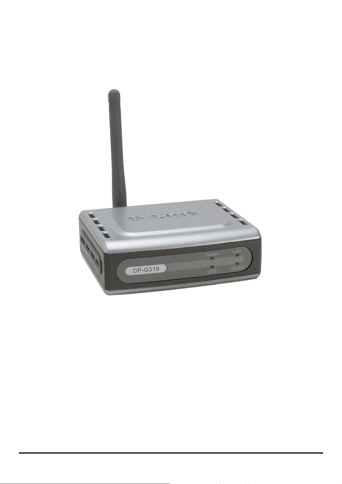
Introduction
The D-Link DP-G310 Print Server is an 802.11g Wireless USB 2.0 high-speed print
server that also can con nect to your Ethernet/Fast Ethernet network anywhere you
wish to locate printer serv ices . The DP-G310 manages the flow of print files from
workstations or file servers to connected printers, delivering print jobs to printers
much faster than a file server or a PC acting as a print server can. With one USB 2.0
port, the DP-310 can connect to almost any printer with a USB connector.
The DP-G310 includes easy-to-use software to install on most Windows-based
networks. Protocol support for TCP/IP, NetBEUI, and AppleTalk are provided to
ensure seamless connection to major networking Operating Systems.
The DP-G310 has a built in Web- Bas e d management feature that allows users to
easily configure and manage multiple print queues through TCP/IP. The DP-G310
also supports Telnet as an alternative method to configure the unit.
The DP-G310 improves ne twork printing services in the following ways:
The DP-G310 picks up the worklo ad of manag ing print file traffic to its connected
printers. This provides workload relief to your file servers, and allows the file servers
full capacity to be used for file access or other direct services to network users. On
peer-to-peer networks, workstations can print directly to the Print Server without
increasing the load of another workstation or server.
The DP-G310’s USB printer port is USB 2. 0 por t , which can transmit to
high-speed laser printer much faster than a PC’s USB printer port. High-speed laser
printer connected to the Print Server’s USB port can be operated at their full
1
Page 7

capacity.
Because the DP-G310 is very portable and inexpensive compared to a PC-based
print server, and Print Server connects to your file servers through the network,
printers can be deployed to locations of maximum co nvenience to users.
The DP-G310 offers extrao r di nary flexibility, operating with all major network
operating systems and protocols:
TCP/IP
UNIX lpr/lpd (HP-UX, SunOS, Solaris, SCO, UnixWare, IBM AIX) Windows NT/2000,
Windows 95/98SE/ME, Windows XP/Vista, NetWare 5.x NDPS LPR Remote
Printing
NetBEUI
Windows NT/2000/XP, Windows 95/98SE/ME, Windows for Workgroups, Microsoft
LAN Manager, IBM LAN Server
AppleTalk
MacOS EtherTalk
Furthermore, the print se rver features a useful software: PS-Wizard. PS-Wizard is
an user-friendly program used to complete further settings for the print server, and
assist you to easily add a printer on your computer. See also the “Using The
PS-Wizard” chapter in this manual for the details. The print server also supports
configuration and management via the Telnet protocol for networks without
Windows-compatible machines.
2
Page 8

External Features
Port Connector
The DP-G310’s USB port is located on its rear panel. The port is configurable using
the Web Configuration Interface or the print server’s Telnet interface. The Print
Server’s Web configuration permits users to configure settings through the web
browser.
Default IP Address of DP-G310 is set as automatically getting from DHCP server or
Router which build-in DHCP server.
NOTE: The PC’s IP Address must be in the same subn et as the print server’s IP
Address for the two devices to commun icat e. (For example, if print server’s IP
Address is 192.168.0.10, with a subnet mask of 255.255.255.0, then your
computer’s IP Address should be 192.168.0.x, where x is a value between 1-254,
excluding 10.)
3
Page 9

Rear Panel Connectors
USB Port Connector
DC Power
Connector
Antenna
Network Cable
Connector
Reset
Network Cable Connector
The Print Server’s rear panel features an RJ-45 connector for connecti on to
10Base-T Ethernet cabling or 100Base-TX Fast Ethernet cabling (which should be
Category 5 twisted-pair cable). The port supports the NWay protocol, allowing the
Print Server to automatically detect or negoti ate the transmission speed of the
4
Page 10

network.
Antenna Connector
Connect the Wireless LAN antenna to the Antenna Connector to have better
signaling of Wireless.
USB Port Connector
The rear panel of the print server featu res the USB port connector. Plug thi s
connector directly into the USB port on your network printer via a USB cable.
Reset Button
Press and release this button to reset the Print Server; or pre ss and hold th is but ton
for three seconds until the USB LED on the front panel light up and then release the
button, the Print Server will resume the factory default settings.
DC Power Connector
The DC power input connector is located on the Print Server ’s rear panel and is
labeled DC 5V.
5
Page 11
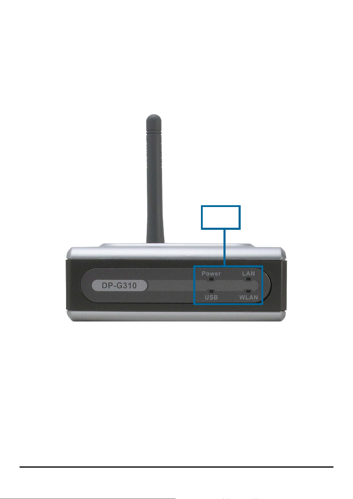
Front Panel
LED Indicators
The front panel of the print server features four LED indicators:
LEDs
Power
Stea dy green confirms that the Print Server is powered ON.
USB
Lights up to indicate printing activity.
LAN
S teady green confirms that the Print Server has a good connection to the Ethernet or
Fast Ethernet network. The indicator blinks off briefly to indicate that the Print Server
is receiving or transmitting from the network.
6
Page 12

WLAN
Steady green indicates a pr oper wireless network connection. The indicator blinks
off briefly to indicate that the Print Server is receiving or transmitting from the
network.
These four indicators are also used by the Prin t Se rver’s Power-ON Self Test (POST)
to indicate any hardware failures.
Wireless Basics
D-Link wireless products are based on industry standards to provide easy-to-use
and compatible high-speed wireless connectivity wit hin your home, business or
public access wireless networks. D-Link wireless products allow you to access the
data you want, when and where you want. You will be able to enjoy the freedom that
wireless networking brings.
A wireless LAN (WL AN) is a cellular computer network that transmits and receives
data with radio signals instead of wires. WLANs are use d in creasingly in both home
and office environments, and pu blic areas such as airports, coffee shops and
universities. Innovative ways to utilize WLAN technology are helping people to work
and communicate mor e efficiently. Increased mobility and the absence of cabling
and other fixed infrastructure have proven to be beneficial for many users.
Wireless users can use the same applications they use on a wired network.
Wireless adapter ca r d s used on laptop and desktop systems support the same
protocols as Ethernet adapter cards.
7
Page 13

People use wireless LAN technology for many different purposes:
Mobility
Productivity increa ses when people have access to data in any location within the
operating range of the WLAN. Management decisions based on real-time
information can significantly improve worker efficiency.
Low Implementation Costs
WLANs are easy to set up, manage, change and relocate. Networks that frequently
change can benefit from WLANs ease of implementation. WLANs can operate in
locations where inst allation of wiring may be impractical.
Installation and Netw or k Expansion
Installing a WLAN system can be fast and easy and can eliminate the need to pull
cable through wa lls and ceilings. Wireless technology allows the network to go
where wires cannot go – even outside the home or office.
Scalability
WLANs can be configured in a variety of topologies to meet the needs of specific
applications and installations. Configurations are easily changed and range from
peer-to-peer networks suitable for a small number of users t o lar ger infrastructure
networks to accommodate hundreds or thousands of users, depending on the
number of wireless devices deployed.
Inexpensive Solution
Wireless network devices are as competitively priced as conventional Ethernet
network devices.
Standards-Based Technolo gy
Based on the IEEE 802.11g standard, the DP-G310 is interoperable with existing
compatible 2.4GHz wireless technology with da ta transfer speeds of up to 54Mbps
∗
∗ Maximum wireless signal rate base d on IEEE Standard 802.11g specificat io ns .
Actual data throughput will vary. Network conditions and environmental factors,
including volume of ne twork traffic, building materials and construction, and network
8
Page 14

when used with other D-Link devices.
Wireless Installation Considerations
Installing Consideratons
The D-Link DP-G310 lets you print through your net work, using a wireless
connection, from virtually anywhere within its operating range. Keep in mind,
however, that the number, thickness and location of walls, ceilings, or other objects
that the wireless signals must pass through, may limit the range. Typical ranges vary
depending on the types of materials and background RF (radio frequency) nois e in
your home or business. The key to maxinmizing wireless range is to follow these
basic guidelines:
1. Keep the antenna of the DP-G310 in an upright position.
2. Keep the number of walls and ceilings between the DP-G310 and other
network device s to a minimum. Each wall or ceiling can reduce your D-Link
wireless products range from 3-90 feet (1-30 meters). Position your devices
so that the number of walls or ceilings is minimized.
3. Be aware of the direct line between network devices. A wall that is 1.5 feet
thick (0.5 meters), at a 45-degree angle appears to be almost 3 feet (1meter)
thick. At a 2-degree angle it looks over 42 feet (14 meters). Polistion devices
so that the signal will travel straight through a wall or ceiling (instead of at an
angle) for better reception.
4. Building materials can impede the wireles s signal. A solid metal door or
aluminum studs amy h a v e a negative effect on range. Try to position
wireless devices and computers with wire less adapters so that the signal
passes through drywall or open doorways and not other materials.
5. Keep your product away (at least 3-6 feet or 1-2 meters) from electrical
overhead lower actual data throughput rate.
9
Page 15

devices or appliances that generate extreme RF noise.
Setting up the DP-G310
Installing the Print Server
WARNING: Configuration problems may result if the Print Server is powered up
without first establishing its network connection.
Follow this procedure to avoid complications at the configuration stage.
1. Confirm proper operation of the print e rs to be connected to the DP-G310.
2. When you have confirmed proper operation of the printer, switch its power
OFF.
3. Confirm that your network is operating normally.
4. Connect the DP-G310 RJ-45 Connector to the network, using an Ethernet
CAT5 cable.
5. While the printer is powered OFF, install the DP-G310 USB port connector
into the USB port on the network printer using a USB cable.
6. Switch ON the connected printer.
7. Plug the AC power adapter’s DC output plug into the DC 5V power socket
on the rear panel of the Print Server.
8. Plug the power adapter into a power outlet. This will supply power to the
Print Server, as it has no external power switch. The green Power LED on
the Print Server’s front panel should illuminate steadily, and the Print
Server’s Self-Test will proceed.
10
Page 16

Power ON Self-Test
Every DP-G310 has been factory-tested to operate properly.
When the DP-G310 is powered ON, it also automatically performs a Self-Test on
each of its major components. The final result of the Self-Test is signaled by the
state of the USB LED indicator following the Self-Test. Preliminary to the actual
component tests, the four LED indicators are tested to confirm their steady and
flashing operation.
Immediately after power-up, all four of the green LEDs should illuminate stead i l y f o r
several seconds. Then the USB LED should light OFF. Irregularity of any of the four
LEDs during these LED tests may mean there is a problem with the LEDs
themselves.
The actual component tests immediately follow the LED tests. A normal (no fault)
result is signaled by a simultaneous flashing of the USB LED three times, followed
by a quiescent state with the USB LED dark.
If the Self-Test routine traps any component error, then following the LED tests the
Self-Test will halt and the USB LED will continuously signal the error according to
the following table. In the event of any such error signal, contact your dealer for
correction of the faulty unit.
11
Page 17
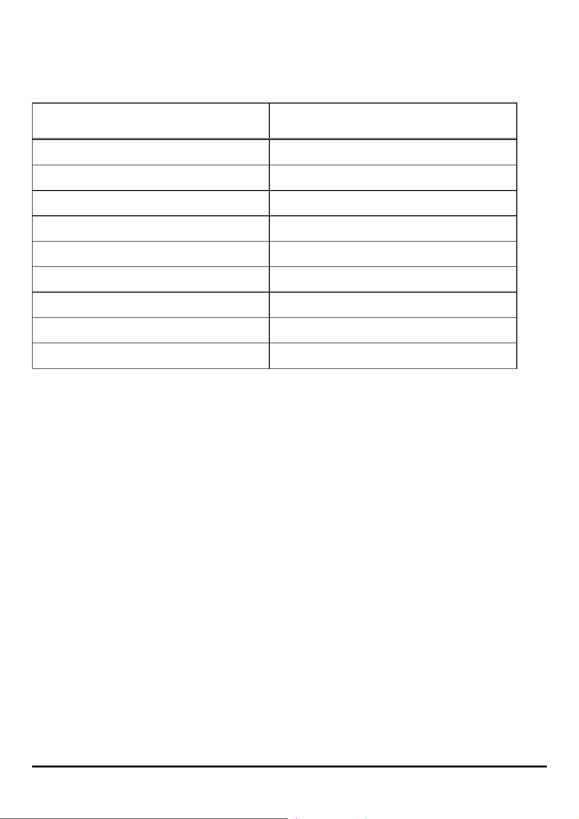
USB LED Faulty Component
On DRAM error
1 long 3 short Flash Protected
1 long 5 short Flash Erase/Program error
1 long 6 short LAN Controller error
1 long 14 short LAN MII error
1 long 15 short WLAN Initial error
1 long 16 short WLAN Access error
1 long 18 short USB error
1 long 19 short PCI error
12
Page 18
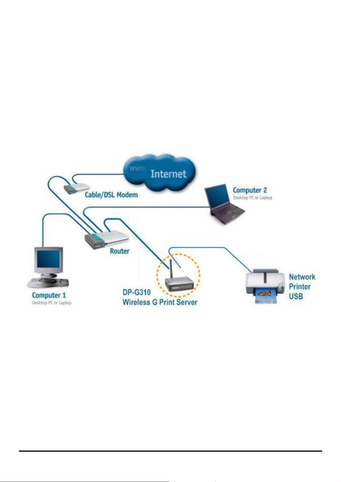
Getting Started
Below is a sample network using the DP-G310. The DP-G310 has a built- in
Web-based management feature that allows users to easily configure and manage
multiple print queues through TCP/IP.
For a list of printers that are compatible with the DP-G310, please see the Appendix
in this manual. The compatibility list is not comprehensive. Even if it is not included
in the list, your printer may be compatible with the DP-G310.
13
Page 19

Using PS-Wizard
This chapter will introduce you the installation and operation of a useful software
program – PS-Wizard.
Auto-Run Installation
Insert the Installation CD-ROM into your computer’s CD-ROM drive to initiate the
Auto-Run program. The content of the Inst all at ion CD-ROM includes:
y View Quick Installation Guide - click to preview the Quick Installation Guide in
PDF format f or step-by-step in structions of the print server Installation.
• View Manual – click to preview the User's Guide in PDF format for detailed
information of the pr int server.
• Install Acrobat Reader – click to launch Acrobat Reader for the viewing and
printing of PDF files in the Installation CD-ROM.
• Install PS-Wizard – click to install PS-Wizard to complete further settings for
the print server, such as:
- Changing IP address
- Adding a printer on your computer in the easiest way.
• Close – click to close the Auto-Run program.
14
Page 20
PS-Wizard
To avoid the conflict in your network, you can use PS-Wizard to change the related
settings of your print server (such as the IP address) after finishing the installation of
PS-Wizard on your PC.
Installing PS-Wizard
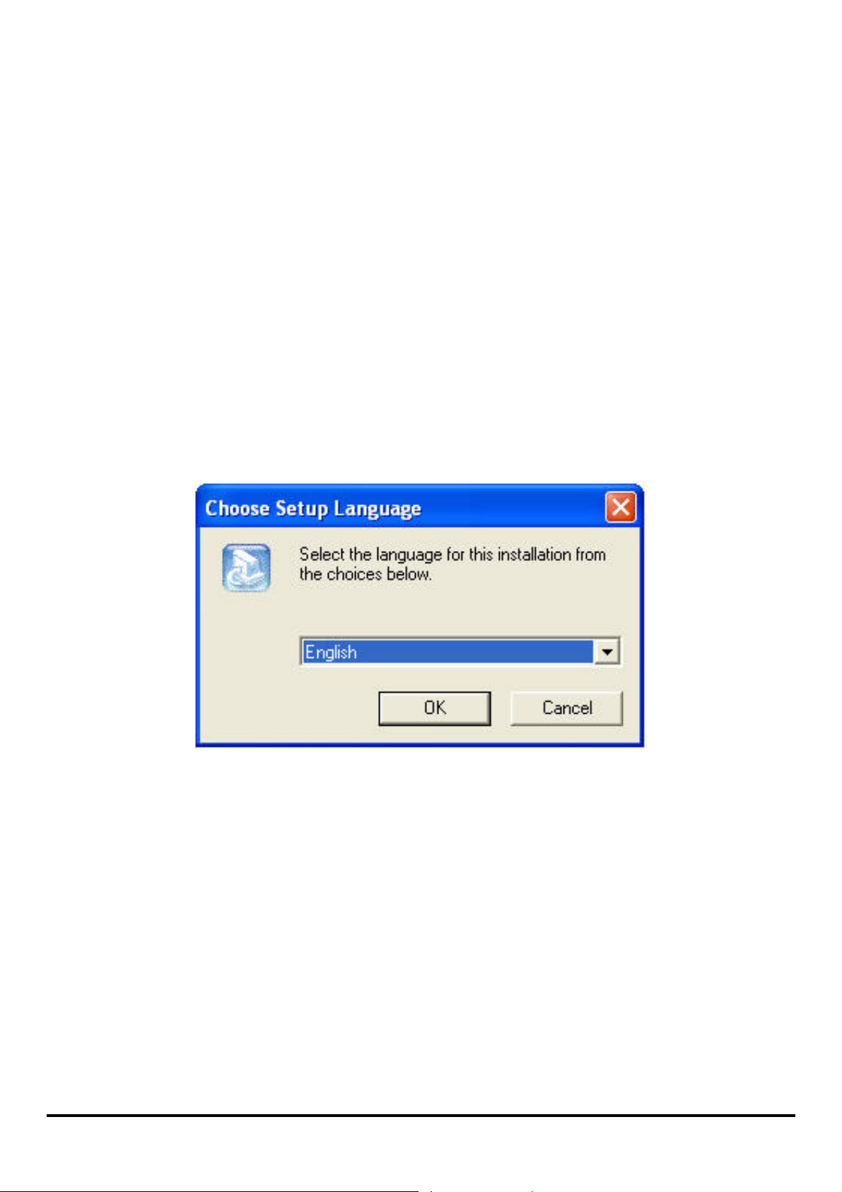
1. Click the PSWizardSetup icon of the Installation CD-ROM, and then the system
will prompt a window for you to select a desired setup language from its
pull-down menu. After done the selection of language, click OK button to
continue.
15
Page 21
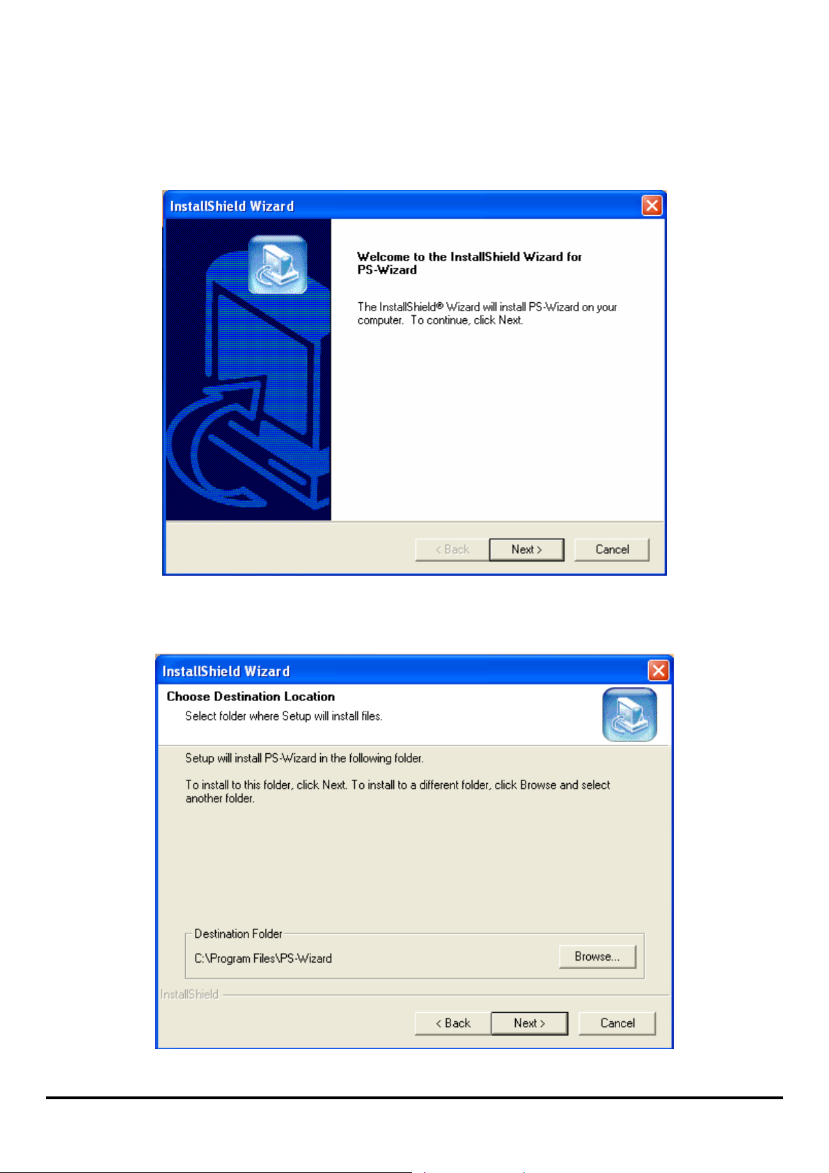
2. Click Next> button in th e we lcome window of In stallShield Wizard.
3. Specify the destination location by pressing Browse… button. Otherwise,
leave the default setting and click Next> button to continue.
16
Page 22
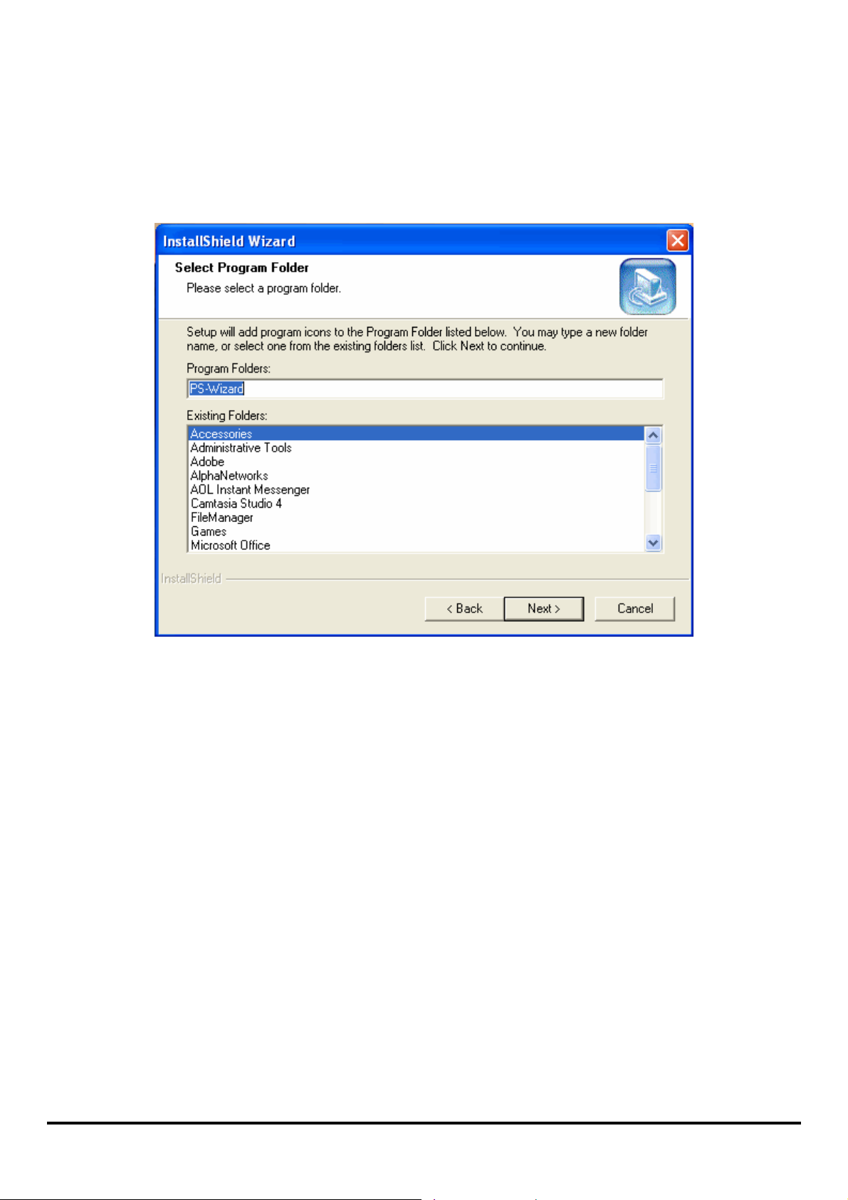
4. You may enter a new folder name in the Program Folder field if you want to
change the default name. Oth erwise, you may leave the default setting and click
Next> button to go on the installation.
17
Page 23
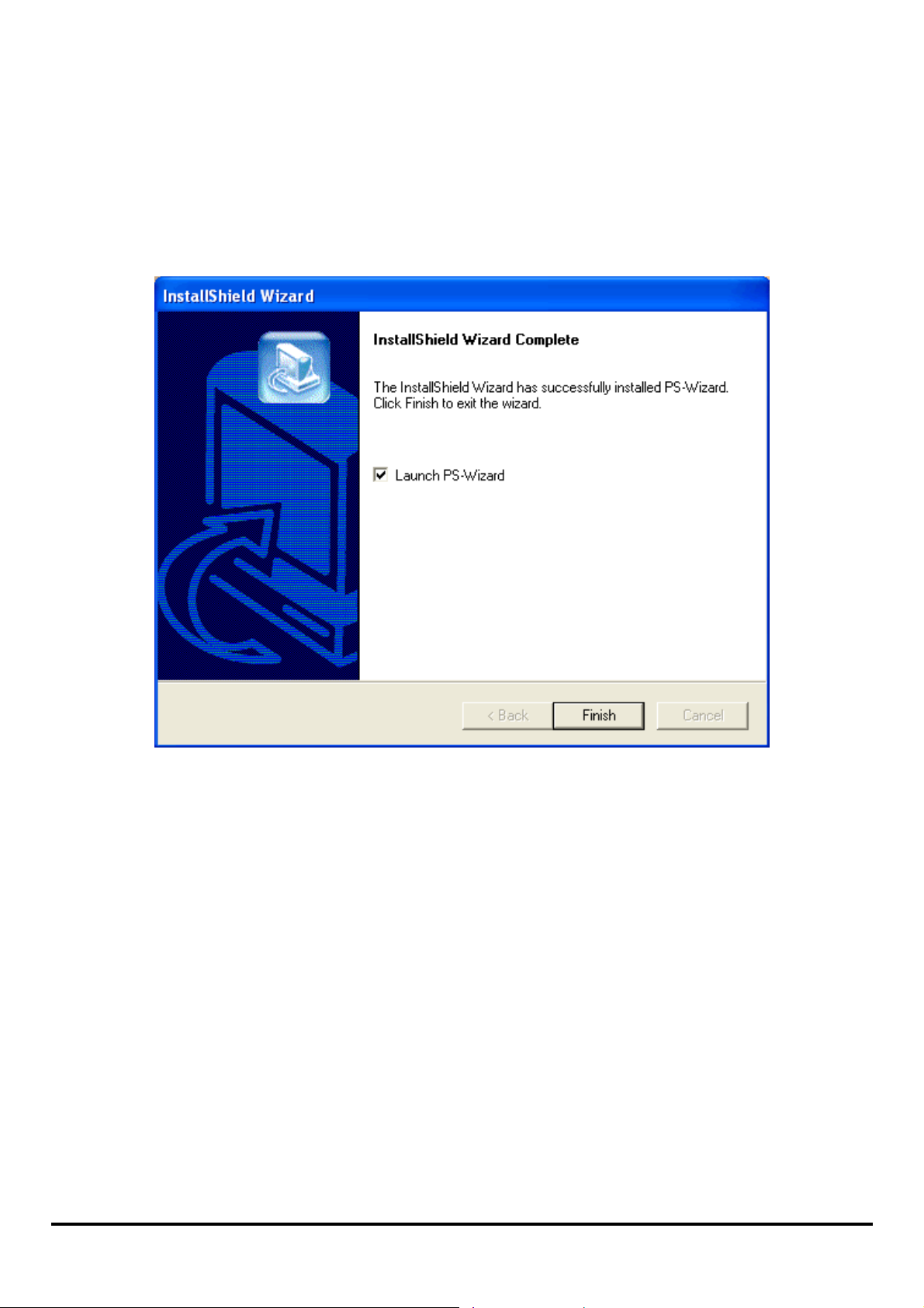
5. The InstallShield Wizard starts to install the software, and the Progress bar
indicates the installation is proceeding until the followi ng window sh ows up. C lick
Finish button to complete the installation.
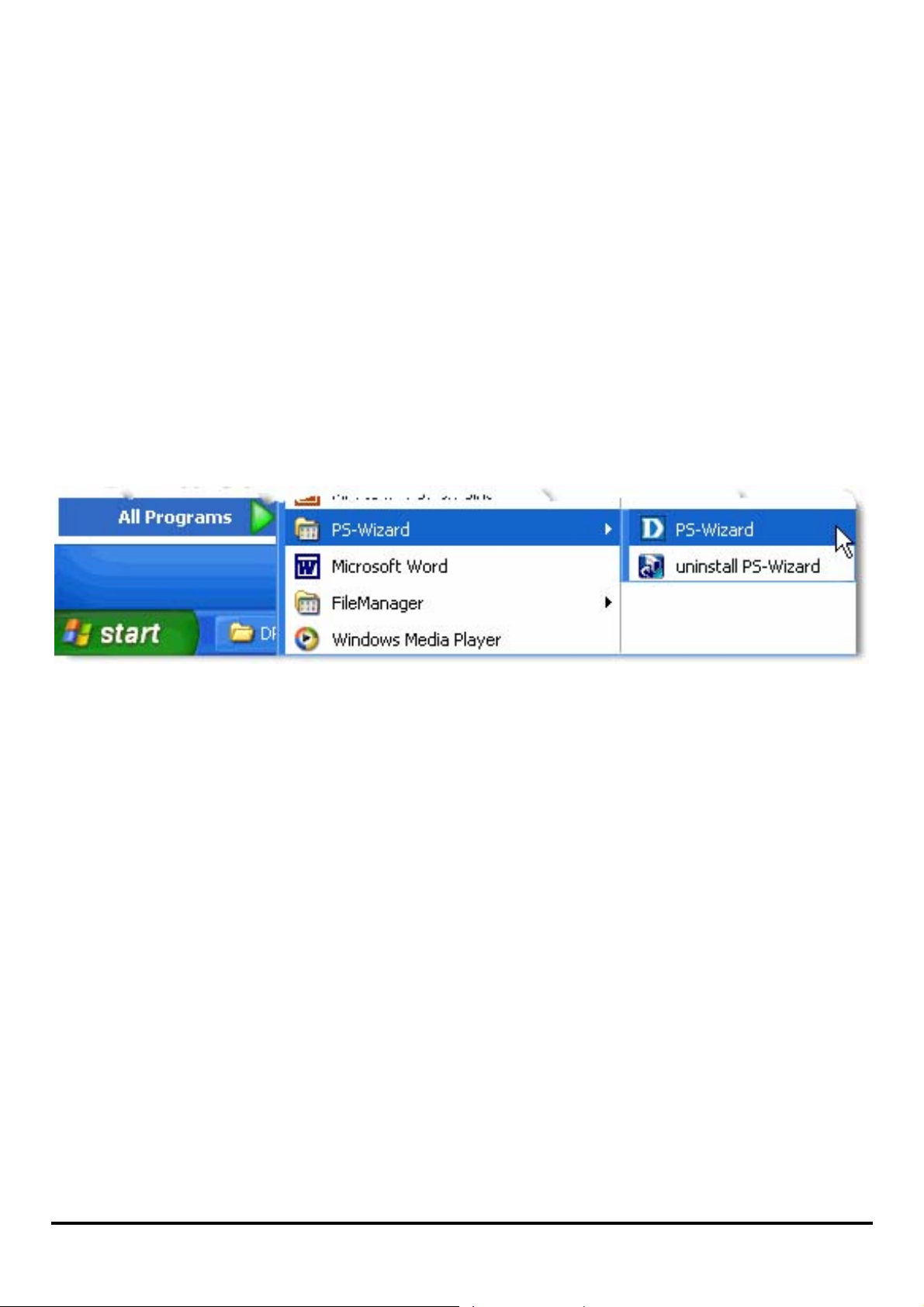
After installing the program, the application program for the print server is
automatically installed to your computer, and creates a folder in StartÎ
ProgramsÎ PS-Wizard.
18
Page 24
Using PS-Wizard
PS-Wizard, supports for Windows 2000/XP/2003/Vista, is a simple and useful tool
for you easily adding a printer on your computer in order to quickly start your printing
task without any complicated configuration. That is, the main goal and advantage of
the PS-Wizard is to let you add a printer on your PC in the easiest way.
Furthermore, the PS-Wizard als o allows you to set up IP addresses of pr int server,
such as IP address, Subnet Mask address, and default Gateway address.
Go to StartÎ ProgramsÎ PS-Wizard, and select PS-Wizard.
19
Page 25

Print Server: This field allows you to manually discover the connected print
server and to do further configuration of the print server that is selected from the
list.
20
Page 26
LAN: You may also to sp ecify dynamic or st atic IP add ress for yo ur print serv er.
Then click Apply button to implement the new setting.
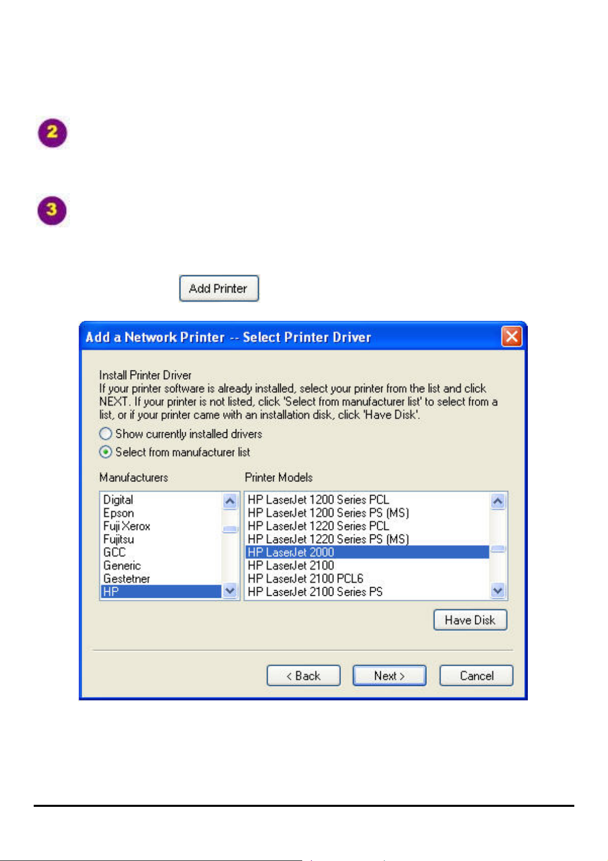
Port Information: This is the main function of the PS-Wizard for you to easily
add a printer on your computer.
To add a printer, click
, then the following window will display.
21
Page 27
The wizard provides three ways for you to select printer driver:
1. Show current installed drivers:
You may select this option, “Show currently installed drivers”, to check if the
same printer driver already exis ted for u se. If not, you may try the next me thod. After
done the selection of printer driver, click Next> button to continue.
2. Select from manufacturer list :
Check this option, “Select from manufacturer list”, to man u ally select your printer
from drop-down menus by brand and model. Click Next> button to continue when
you find a desired driver. If not, try the last way (H ave Disk). Af ter done the selection
of printer driver, click Next> button to continue.
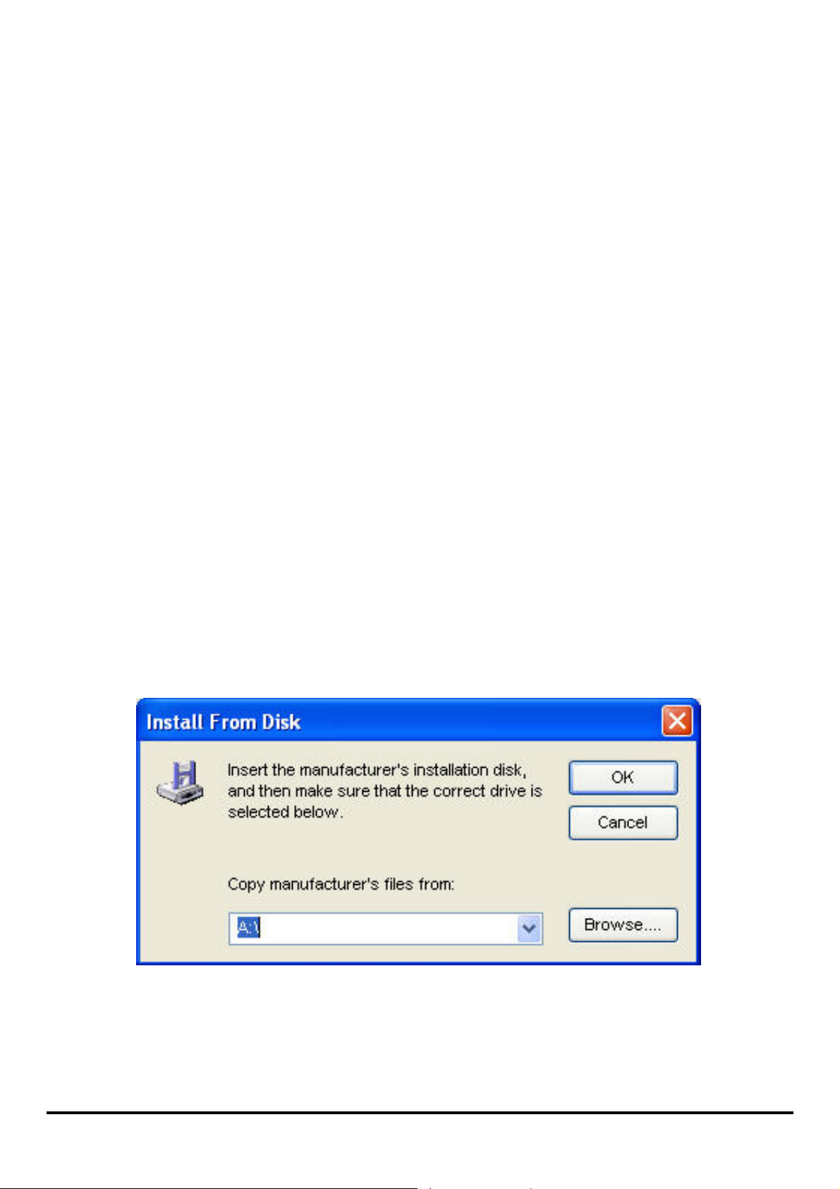
3. Have Disk:
Click Have Disk button to bring up the following window. Insert the manufacture’s
installation CD-ROM to install the printer driver. After the correct driver is selected,
click OK button to continue.
After done the selection of printer driver, the wizard will ask you to confirm your
22
Page 28
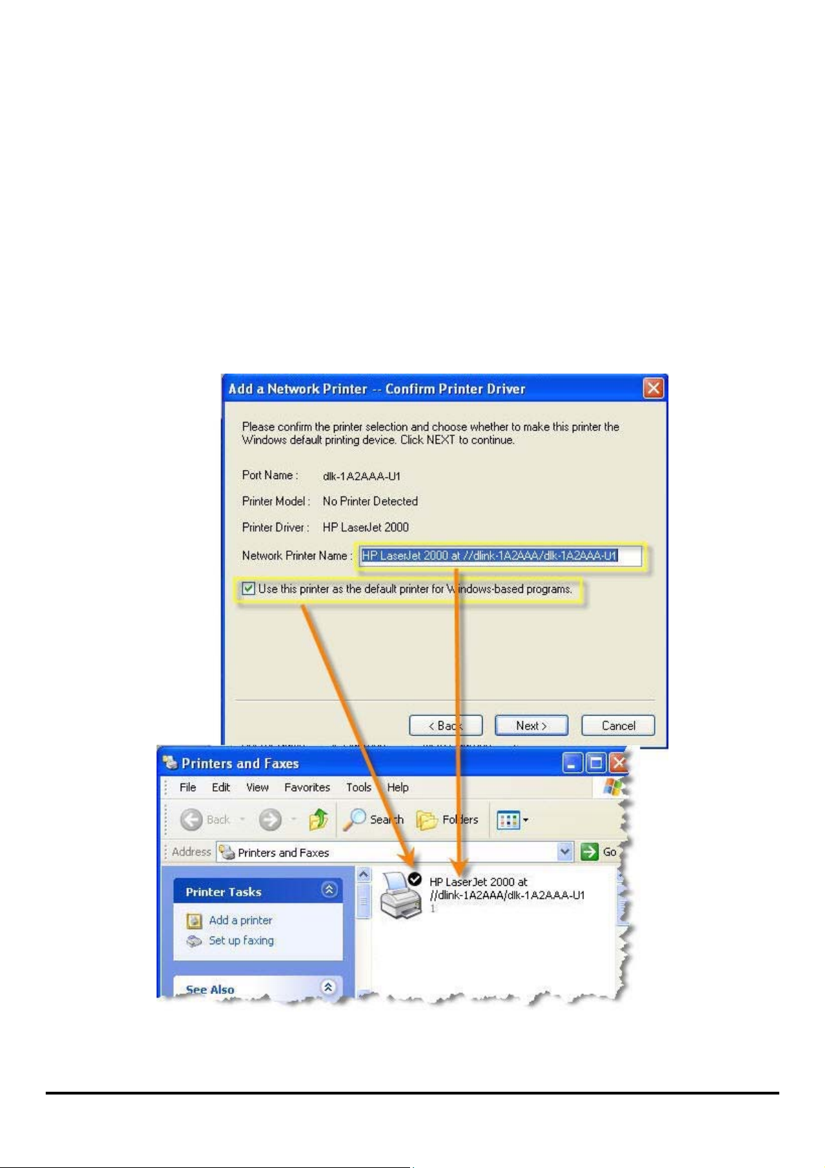
selection again in the f ollowi ng win dow. Beside, you are allowed to edit the name of
the printer in the field “Network Printer Name” and enable this printer as the default
printer by checking the box “Use this printer as the default printer for
Windows-based programs”.
After you done the verification and configuration in the following window, click Next>
button to continue. Then the printer (e.g. HP Laser 2000 used in this manual) will be
auto-created in Windows’ Printers and Faxes window as the following illustration.
When the following window shows up, you may do print test by clicking Print Test
23
Page 29
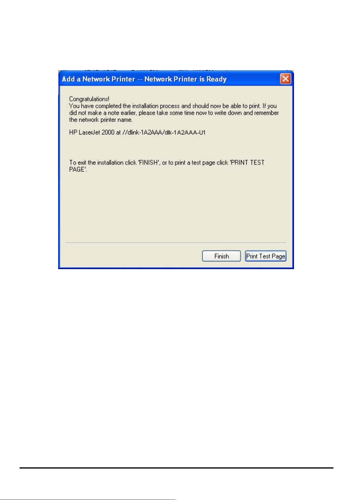
Page button to check if you can do pr inting normally. If yes, then click Finish button
to exit the installation window and now you may start your printing tasks.
24
Page 30
Using the Web Configuration
Home
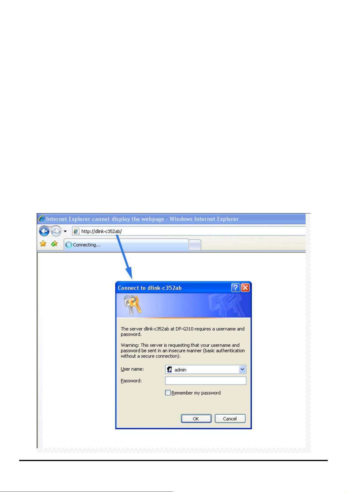
To begin managing the DP-G310, simply launch the browser (e.g. Internet Explorer
6.0 used in this manual) you have installed on your computer and direct it to the URL
address: dlink-xxxxxx, where xxxxxx are the last six digits of DP-G310’s MAC
address. The MAC address can be found on the bottom side of the DP-G310
device.
When you enter the correct URL, a password input dialog will pop up the following
screen. Type “admin” in the User name field, leave the Password field as blank,
and then click OK button.
25
Page 31

Then the main screen of the print server’s configuration will appear (see below). In
addition to the product information, you can access and control the print server’s
configuration through five links on the top of this main scree n: Setup, Advanced,
Maintenance, Status, and Help. You may click a desired link from the bar, to
display its submenu and select a desired option listed in the left column, a nd then
the corresponding content will show up in the center column.
26
Page 32

SETUP > Print Server Setup
The Print Server Setup screen allows you to modify the Print Server Name and
Port Name, as below shows. D-Link does not recommend changing these se ttings
unless asked to do so by your network administrator.
Print Server Name
In this field, you can configure the basic information of print server. The basic
information contains a name of the print server, assigned in Server Name field, and
a location for the print server, assigned in Location (optional) field.
27
Page 33

Port Settings
In this field, you can assign the Port Name for the print server, and the description
for the Printer port. It also allows you to select the PJL Printer setting (Yes or No).
NOTE: PJL (Printer Job Language) has certain job requirements that must be
met to work correctly. For more information, please refer to your printer's
manual.
Once you have changed the settings in each option, click Apply Settings to store the
settings, or Cancel to abandon.
28
Page 34

SETUP > LAN Setup
The LAN Setup screen allows you configure the local network settings of print
server. Please note that this section is optional and you should not need to change
any of the settings here to get print server up and running.
TCP/IP
This field allows you to assign IP addres s in manual or aut oma tic me tho d. Whe n you
choose Manually Assign, you should enter the related information in the following
boxes, including IP Address, Subnet Mask, and Default Gateway.
Once you have changed the settings in each option, click Apply Settings to store the
settings, or Cancel to abandon.
29
Page 35

SETUP > Wireless Setup
The Wireless Setup screen allows you configure the wirelessLAN settings of print
server.
30
Page 36

Wireless Interface
Select one of the two c onnection m odes: Infrastructure (default) or Ad-Hoc. Assign
the SSID in the SSID box. You can manually type the name or select one from the
drop-down list. To search the available wireless access point within the network,
click the Site Survey button. Select a channel from the Wireless Channel list, and
a data transmit rate from the Transmission Rate list.
Encryption
In this section, you can select Disable, WEP Encryption or WPA-PSK /
WPA2-PSK.
Click the Disable radio button to disable the encryption function of wireless network.
Click the WEP Encryption radio button to select Length and Format of WEP
encryption. Click either 64bits or 128bits in Length, select the WEP key format as
ASCII (ASCII characters) or HEX (hexadecimal) in Format, and enter the key(s) for
the network in the Key box (1-4). 64bits WEP encryption uses a 10 hexadecimal
character key. The WEP encryption key must match the WEP se t tin gs o n yo ur AP or
wireless router to connect properly.
Click WPA-PSK / WPA2-PSK to use a WPA-PSK / WPA2-PSK passphrase. Enter a
WPA-PSK / WPA2-PSK passphrase or key used on your network.
SETUP > Printer Setup
The Printer Setup screen allows you install the printer dr i ver s for the printer
currently connected to your print server.
31
Page 37
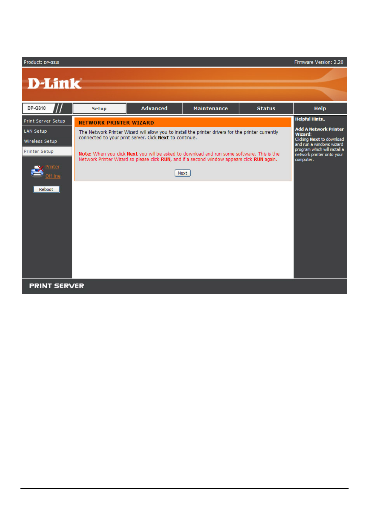
Network Printer Wizard
Clicking Next to download and run a windows wizard program which will install a
network printer onto yo ur computer. When you click Next you will be asked to
download and run some software.
32
Page 38

The above screen is the Network Printer Wizard so please click RUN, and if a
second window appears as below click RUN again.
33
Page 39

Please select the print e r required, then click NEXT to continue.
The wizard provides three ways for you to select printer driver:
1. Show current installed drivers:
You may select this option, “Show currently installed drivers”, to check if the
same printer driver already exis ted for u se. If not, you may try the next me thod. After
done the selection of printer driver, click Next> button to continue.
34
Page 40

2. Select from manufacturer list :
Check this option, “Select from manufacturer list”, to man u ally select your printer
from drop-down menus by brand and model. Click Next> button to continue when
you find a desired driver. If not, try the last way (Have Disk). After done the selection
of printer driver, click Next> button to continue.
35
Page 41

3. Have Disk:
Click Have Disk button to bring up the following window. Insert the manufacture’s
installation CD-ROM to install the printer driver. After the correct driver is selected,
click OK button to continue.
36
Page 42
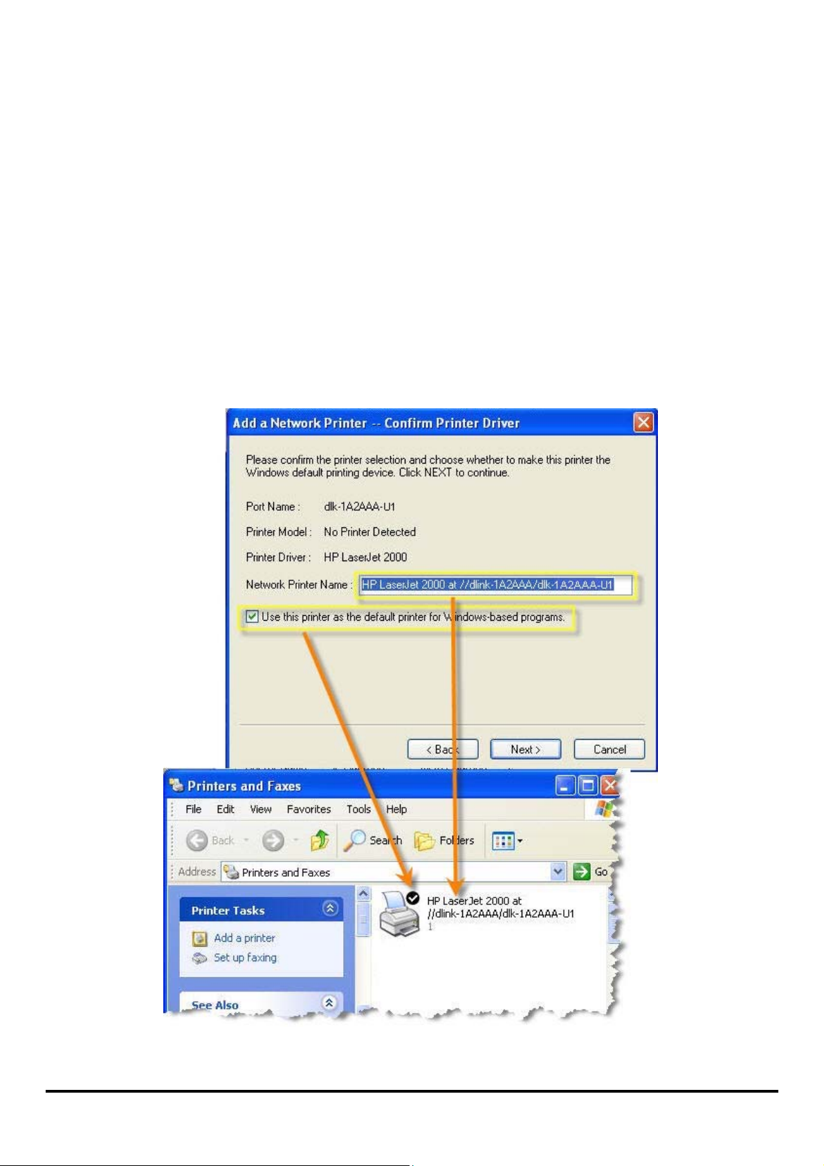
After done the selection of printer driver, the wizard will ask you to confirm your
selection again in the f ollowi ng win dow. Beside, you are allowed to edit the name of
the printer in the field “Network Printer Name” and enable this printer as the default
printer by checking the box “Use this printer as the default printer for
Windows-based programs”.
After you done the verification and configuration in the following window, click Next>
button to continue. Then the printer (e.g. HP Laser 2000 used in this manual) will be
auto-created in Windows’ Printers and Faxes window as the following illustration.
37
Page 43

When the following window shows up, you may do print test by clicking Print Test
Page button to check if you can d o printing normally. If yes, click OK button to close
the D-Link Add Printer Wizard dialogue screen.
38
Page 44

If yes, then click Finish button to exit the installation window and now you may start
your printing tasks.
39
Page 45

ADVANCED > Advanced LAN
The Advanced LAN screen allows you to further network setting of print server,
while you are recommended better not to change the settings unless instructed to
modify the setting by your network administrator. The Advanced LAN screen
contains these fields : TCP/IP, Microsoft Network, and AppleTalk.
40
Page 46

TCP/IP
This field contains four options that allow yo u to con figure the TCP/IP setting: DNS
Server Address, UPnP, Mac Bonjour/Rendezvous, and Second HTTP Port.
UPnP: This option allows you to enable or disable UPnP function.
Mac Bonjour/Rendezvous: This option allows you to enable or disable Mac
Bonjour/Rendezvous function.
Second HTTP Port: This opti on all ow s y ou to en a ble or disable Second HTTP
Port for remote Web Configuration and IPP Printing.
Microsoft Network
Enter the name of the Workgroup that you want the print server associated with in
this field.
AppleT alk
Enter the AppleTalk Zone name in the box. In the following options, enter the related
configuration, such as the printer type.
Chooser Name
Printer T ype
PostScript Level
Font Group
: Display the print server's port name.
: Enter the printer's type in this box.
: Select from the pull-down menu (Level 1 or Level 2).
: Select from the pull-down menu.
Once you have changed the settings in each option, click Apply Settings to store the
settings, or Cancel to abandon.
41
Page 47
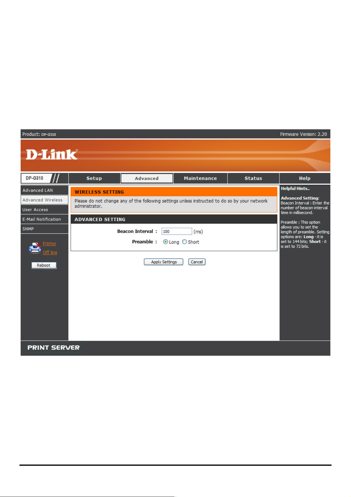
ADVANCED > Advanced Wireless
The Advanced Wireless screen allows you to configure further wireless network
setting of print server.
Advanced Setting
Enter a number for the beacon interval in milliseconds in the Beacon Interval box.
Click the length of th e preamble as Long (144bits) or Short (72bits) in Preamble.
42
Page 48

ADVANCED > User Access
The User Access screen allows you to create and maintain an authorized list of
users that are allowed to access the print server.
User Access
By configuring the Enable Authorised User List option (Yes), the user in the User
List is permitted to access the print server. Any user who is not added in the User
List will not be allowed to access the print server. Once you have changed the
settings in each option, click Apply Settings to store the settings, or Cancel to
43
Page 49

abandon.
Authorised Users
You can add or delete any user to or from the User List. The User List at the bottom
of the screen displays the current defined user and related information for the print
server.
44
Page 50

ADVANCED > E-Mail Notification
The E-Mail Notification screen allows you to assign an E-mail address to the print
server, so that your mail of the account can be printed out directly through the printer
(ASCII text only). This screen also allow you choose where to send an email when
the printer status changes.
45
Page 51

Enable E-mail Notification
You can set the print server to send an alert message when the printer status
changes through E-mail. To enable this function, set the Enable e-mail notification
option to Yes. Then, input the administrator's E-mail address in the Destination
e-mail Address field.
E-mail Account Details
You can assign an E-mail addres s to the print server, so that your mail of the
account can be printed out directly through the printer (ASCII text only). To enable
this function, enter the E-mail account in the Print Server E-mail Address field.
Then enter the server address, used to receive your E-mail here, in the Incoming
E-mail (POP3) Server Address field. For Outgoing E-mail (SMTP) Server
Address field, enter the server address that is used to send your E-mail here.
If your mail server needs to verify the user when sending E-mail, Print Server will
apply the E-mail Account (POP3) Name and E-mail Account (POP3) Password
to the mail server.
E-mail Printing
This section is for you to do E-mail Printing configuration, including:
E-mail Printing (ASCII Text Only)
printing.
Check E-mail Interval
check/receive E-mail periodically.
After done the configuration, click Apply Settings to restore the new configuration, or
Cancel to abandon.
: Allow you to set up a time interval in minute in order to
: Allows you to enable or disable the E-mail
46
Page 52

ADVANCED > SNMP
The SNMP screen allows you to use SNMP (Simple Network Management Protocol)
to manage complex networks.
SNMP Management
Community 1/2/3
Right by selecting Read Only or Read/ Write from the pull-down menu.
: Enter a name in the Name frame, and configure the Access
47
Page 53

MAINTENANCE > Password
The Password screen allows you to change the password of the print server by
entering the current password in Current Password field and new password in New
Password and Confirm Password fields. After done the configuration, click Apply
Settings to enable and restore the new password, or Cancel to abandon. Be aware
that the default password of the print server is blank.
48
Page 54

MAINTENANCE > Save/Restore Settings
The Save/Restore Settings screen not only allows you to save the current
configuration in a computer for backup by clicking Save, but also allows you to
reload a configuration that you s aved before by clicking Browse to direct to the
backup file, and then clicking Update Settings for reloading. Beside, you are also
allowed to return the print server to the default settings by clicking Restore Device.
49
Page 55

MAINTENANCE > Firmware Upgrade
The Firmware Upgrade screen displays you the current firmware’s information of
the print server, and also allows you to upgrade the firmware of the pr int server
when a new version of firmware is available.
Click Browse to point to the firmware file, and then click Upgrade.
50
Page 56

MAINTENANCE > Diagnostics
The Diagnostics screen allows you to test the printing for USB port of the print
server. After done the port selection, click Print Test Page to print a test page.
51
Page 57

STATUS > Device Info
The Device Info screen displays the status of your print server, printer, and network
for your reference.
52
Page 58

Print Server Status
This field displays the information of the print server about the firmware version,
MAC/IP address, and up time.
Printer Status
The items in this field display the information of the printer, such as the given name
for the printer, speed, printer status, and status of your printing tasks, etc.
LAN Status
You can monitor the networking st atus in this field, including the network connection,
speed, and the packets status.
STATUS > Network
The Network screen displays the general Network status of your print server,
including:
Auto IP
This field contains the current settings of TCP/IP, including DHCP/BOOTP, UPnP,
and Mac Bonjour/Rendezvous. The items in this field are configured in Advanced
Æ Advanced LAN Æ TCP/IP.
TCP/IP Printing
In this field, you can monitor the status of your printing tasks through TCP/IP.
Microsoft Network Printing
In this field, you can monitor the status of your printing tasks through Microsoft
Network.
Mac AppleT alk Printing
In this field, you can monitor the s t atus of yo ur pri ntin g ta sks th rough Mac AppleTalk.
53
Page 59

54
Page 60
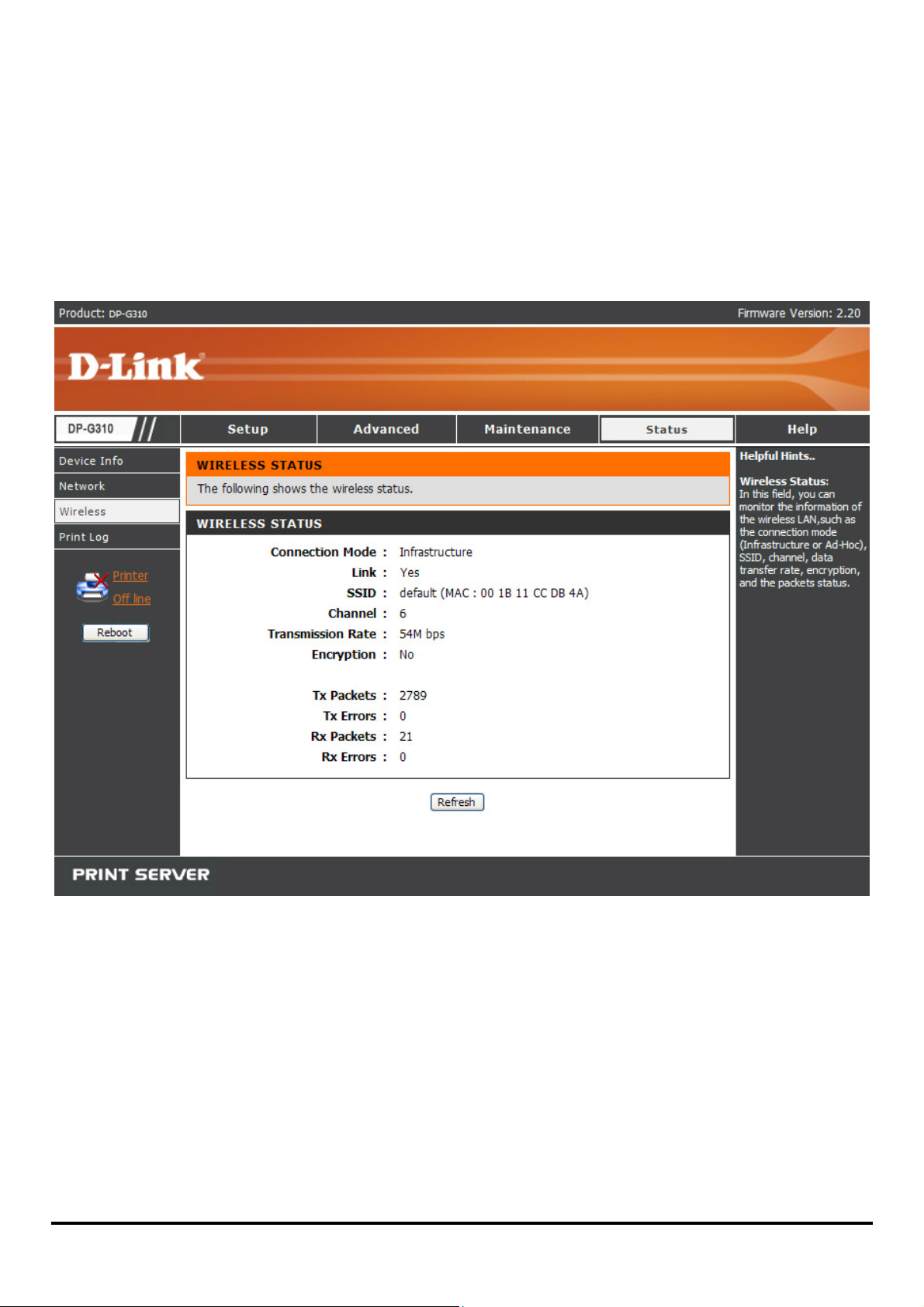
STATUS >Wireless
The Wireless screen displays the information about th e wireless LAN . Click Refresh
to update the information.
Wireless Status
This field displays information about the wireless LAN, such as the Connection
Mode (Infrastructure or Ad-Hoc), SSID, Channel, Transmission Rate, Encryption
and packets status.
55
Page 61

STATUS >Print Log
The Print Log screen displays t he print ing record of the authorized users.
Print Log
The items in this field display the us er (s) information, which include the user(s) MAC
address, IP address, name, and status of printing tasks.
56
Page 62

HELP
The Help screen provides you brief information about the print server for your
reference.
57
Page 63

Reboot
If you want to reset the print server, you may just click the Reboot for restarting.
58
Page 64

Refresh Printer Status
Click Printer to refresh printer status.
59
Page 65

TCP/IP Printing for Windows Vista
Go to Start Î Control Panel Î Printers.
60
Page 66

Click Add a printer.
Select the first option, Add a local printer, and then click Next.
61
Page 67

Select the second option, Create a new port, and highlight Standard TCP/IP Port
from the pull-down menu. Click Next.
62
Page 68

Type the IP address of the print server (e.g. 10.62.31.15 used in this manual), which
can be referred from the PRINTER SERVER STATUS of the print server’s Web
configuration, and then the Port Name will automatically be filled in. Click Next
63
Page 69

Select Custom and click Settings.
64
Page 70

Then the follow screen will shows up, select LPR from the Protocol field.
Then enter the Queue Name, which can be referred from PRINTER STATUS of the
print server’s Web configuration, in the LPR Settings field. Click OK.
65
Page 71

66
Page 72

Highlight the printer, as shown. If the desired printer is not on the list, click Have
Disk and insert the printer driver disk that came with your printer to install the printer
drivers.
Click Next
67
Page 73

Click Next to start installing the printer.
68
Page 74

After clicked Print a test page, a small dialogue box will show up as below. Click
Close.
69
Page 75

Click Finish.
The printer is now ready for printing with Windows Vista on your network.
70
Page 76

TCP/IP Printing for Windows XP
Go to Start Î Printers and Faxes Î Add a Printer.
When the following screen shows up, click Next.
71
Page 77

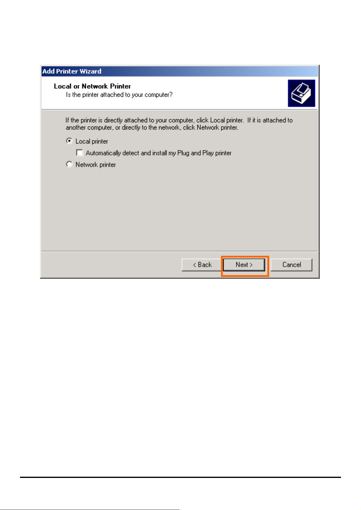
Select the first option, Local printer attached to this computer, and click Next.
72
Page 78

Select the second option, Create a new port, and highlight Standard TCP/IP Port
from the pull-down menu. Click Next.
73
Page 79

Click Next.
74
Page 80

Type the IP address of the print server (e.g. 10.62.31.15 used in this manual), which
can be referred from the PRINTER SERVER STATUS of the print server’s Web
configuration, and then the Port Name will automatically be filled in. Click Next
75
Page 81

Select Custom and click Settings.
76
Page 82

Then the follow screen will shows up, select LPR from the Protocol field.
Then enter the Queue Name, which can be referred from PRINTER STATUS of the
print server’s Web configuration, in the LPR Settings field. Click OK.
77
Page 83

78
Page 84

Click Next.
79
Page 85

Click Finish.
80
Page 86

Highlight the printer, as shown. If the desired printer is not on the list, click Have
Disk and insert the printer driver disk that came with your printer to install the printer
drivers.
Click Next.
81
Page 87

At this screen, you can input a name for the printer, and then click Next.
82
Page 88

Select Yes to print a test page, click Next.
83
Page 89

Click Finish. The printer is now ready for printing with Windows XP on your network.
84
Page 90

TCP/IP Printing for Windows 2000
Go to Start Î Settings Î Printers and Faxes Î Add a Printer.
When the following screen shows up, click Next.
85
Page 91
Select the first option, Local printer attached to this computer, and click Next.
86
Page 92

Select the second option, Create a new port, and highlight Standard TCP/IP Port
from the pull-down menu. Click Next.
87
Page 93

Click Next.
88
Page 94

Type the IP address of the print server (e.g. 10.62.31.15 used in this manual), which
can be checked from the PRINTER SERVER STATUS of the print server’s Web
configuration, and then the Port Name will automatically be filled in. Click Next.
89
Page 95

Select Custom and click Settings.
90
Page 96

Then the follow screen will shows up, select LPR from the Protocol field.
Then enter the Queue Name, which can be referred from PRINTER STATUS of the
print server’s Web configuration, in the LPR Settings field. Click OK.
91
Page 97

92
Page 98

Click Next.
93
Page 99

Click Finish.
94
Page 100

Highlight the printer, as shown. If the desired printer is not on the list, click Have
Disk and insert the printer driver disk that came with your printer to install the printer
drivers.
Click Next.
95
 Loading...