

D-Link DP-692 User Manual

DP-692
Internet Server/Hub
User’s Guide
Rev. 01 (July, 1999)
6DP692H…01
Printed In Taiwan
RECYCLABLE


Wichtige Sicherheitshinweise
1. Bitte lesen Sie sich diese Hinweise sorgfältig durch.
2. Heben Sie diese Anleitung für den spätern Gebrauch auf.
3. Vor jedem Reinigen ist das Gerät vom Stromnetz zu trennen. Vervenden Sie keine Flüssigoder Aerosolreiniger. Am besten dient ein angefeuchtetes Tuch zur Reinigung.
4. Um eine Beschädigung des Gerätes zu vermeiden sollten Sie nur Zubehörteile verwenden,
die vom Hersteller zugelassen sind.
5. Das Gerät is vor Feuchtigkeit zu schützen.
6. Bei der Aufstellung des Gerätes ist auf sichern Stand zu achten. Ein Kippen oder Fallen
könnte Verletzungen hervorrufen. Verwenden Sie nur sichere Standorte und beachten Sie
die Aufstellhinweise des Herstellers.
7. Die Belüftungsöffnungen dienen zur Luftzirkulation die das Gerät vor Überhitzung
schützt. Sorgen Sie dafür, daß diese Öffnungen nicht abgedeckt werden.
8. Beachten Sie beim Anschluß an das Stromnetz die Anschlußwerte.
9. Die Netzanschlußsteckdose muß aus Gründen der elektrischen Sicherheit einen
Schutzleiterkontakt haben.
10. Verlegen Sie die Netzanschlußleitung so, daß niemand darüber fallen kann. Es sollete
auch nichts auf der Leitung abgestellt werden.
11. Alle Hinweise und Warnungen die sich am Geräten befinden sind zu beachten.
12. Wird das Gerät über einen längeren Zeitraum nicht benutzt, sollten Sie es vom Stromnetz
trennen. Somit wird im Falle einer Überspannung eine Beschädigung vermieden.
13. Durch die Lüftungsöffnungen dürfen niemals Gegenstände oder Flüssigkeiten in das Gerät
gelangen. Dies könnte einen Brand bzw. Elektrischen Schlag auslösen.
14. Öffnen Sie niemals das Gerät. Das Gerät darf aus Gründen der elektrischen Sicherheit nur
von authorisiertem Servicepersonal geöffnet werden.
15. Wenn folgende Situationen auftreten ist das Gerät vom Stromnetz zu trennen und von
einer qualifizierten Servicestelle zu überprüfen:
a– Netzkabel oder Netzstecker sint beschädigt.
b– Flüssigkeit ist in das Gerät eingedrungen.
c– Das Gerät war Feuchtigkeit ausgesetzt.
d– Wenn das Gerät nicht der Bedienungsanleitung ensprechend funktioniert oder Sie mit
Hilfe dieser Anleitung keine Verbesserung erzielen.
e– Das Gerät ist gefallen und/oder das Gehäuse ist beschädigt.
f– Wenn das Gerät deutliche Anzeichen eines Defektes aufweist.
16. Bei Reparaturen dürfen nur Orginalersatzteile bzw. den Orginalteilen entsprechende Teile
verwendet werden. Der Einsatz von ungeeigneten Ersatzteilen kann eine weitere
Beschädigung hervorrufen.
17. Wenden Sie sich mit allen Fragen die Service und Repartur betreffen an Ihren
Servicepartner. Somit stellen Sie die Betriebssicherheit des Gerätes sicher.
18.Zum Netzanschluß dieses Gerätes ist eine geprüfte Leitung zu verwenden, Für einen
Nennstrom bis 6A und einem Gerätegewicht grßer 3kg ist eine Leitung nicht leichter als
H05VV-F, 3G, 0.75mm2 einzusetzen.

Trademarks
Copyright 1999 D-Link Corporation.
Contents subject to change without prior notice.
D-Link is a registered trademark of D-Link Corporation/D-Link
Systems, Inc.
All other trademarks belong to their respective proprietors.
Copyright Statement
No part of this publication may be reproduced in any form or by
any means or used to make any derivative such as translation,
transformation, or adaptation without permission from D-Link
Corporation/D-Link Systems Inc., as stipulated by the United
States Copyright Act of 1976.
FCC Warning
This equipment has been tested and found to comply with the
limits for a Class A digital device, pursuant to Part 15 of the FCC
Rules. These limits are designed to provide reasonable protection
against harmful interference when the equipment is operated in a
commercial environment. This equipment generates, uses, and
can radiate radio frequency energy and, if not installed and used
in accordance with this user’s guide, may cause harmful interference to radio communications. Operation of this equipment in a
residential area is likely to cause harmful interference in which
case the user will be required to correct the interference at his
own expense.
CE Mark Warning
This is a Class A product. In a domestic environment, this product may cause radio interference in which case the user may be
required to take adequate measures.
VCCI A Warning

Limited Warranty
Hardware:
D-Link warrants each of its hardware products to be free from defects in workmanship and
materials under normal use and service for a period commencing on the date of purchase from
D-Link or its Authorized Reseller and extending for the length of time stipulated by the
Authorized Reseller or D-Link Branch Office nearest to the place of purchase.
This Warranty applies on the condition that the product Registration Card is filled out and
returned to a D-Link office within ninety (90) days of purchase. A list of D-Link offices is provided at the back of this manual, together with a copy of the Registration Card.
If the product proves defective within the applicable warranty period, D-Link will provide
repair or replacement of the product. D-Link shall have the sole discretion whether to repair or
replace, and replacement product may be new or reconditioned. Replacement product shall be
of equivalent or better specifications, relative to the defective product, but need not be identical.
Any product or part repaired by D-Link pursuant to this warranty shall have a warranty period
of not less than 90 days, from date of such repair, irrespective of any earlier expiration of original warranty period. When D-Link provides replacement, then the defective product becomes
the property of D-Link.
Warranty service may be obtained by contacting a D-Link office within the applicable warranty
period, and requesting a Return Material Authorization (RMA) number. If a Registration Card
for the product in question has not been returned to D-Link, then a proof of purchase (such as a
copy of the dated purchase invoice) must be provided. If Purchaser's circumstances require
special handling of warranty correction, then at the time of requesting RMA number, Purchaser
may also propose special procedure as may be suitable to the case.
After an RMA number is issued, the defective product must be packaged securely in the original or other suitable shipping package to ensure that it will not be damaged in transit, and the
RMA number must be prominently marked on the outside of the package. The package must
be mailed or otherwise shipped to D-Link with all costs of mailing/shipping/insurance prepaid.
D-Link shall never be responsible for any software, firmware, information, or memory data of
Purchaser contained in, stored on, or integrated with any product returned to D-Link pursuant
to this warranty.
Any package returned to D-Link without an RMA number will be rejected and shipped back to
Purchaser at Purchaser's expense, and D-Link reserves the right in such a case to levy a reasonable handling charge in addition mailing or shipping costs.
Software:
Warranty service for software products may be obtained by contacting a D-Link office within
the applicable warranty period. A list of D-Link offices is provided at the back of this manual,
together with a copy of the Registration Card. If a Registration Card for the product in question has not been returned to a D-Link office, then a proof of purchase (such as a copy of the
dated purchase invoice) must be provided when requesting warranty service. The term "purchase" in this software warranty refers to the purchase transaction and resulting license to use
such software.
D-Link warrants that its software products will perform in substantial conformance with the
applicable product documentation provided by D-Link with such software product, for a period
of ninety (90) days from the date of purchase from D-Link or its Authorized Reseller. D-Link

warrants the magnetic media, on which D-Link provides its software product, against failure
during the same warranty period. This warranty applies to purchased software, and to replacement software provided by D-Link pursuant to this warranty, but shall not apply to any
update or replacement which may be provided for download via the Internet, or to any update
which may otherwise be provided free of charge.
D-Link's sole obligation under this software warranty shall be to replace any defective software
product with product which substantially conforms to D-Link's applicable product documentation. Purchaser assumes responsibility for the selection of appropriate application and
system/platform software and associated reference materials. D-Link makes no warranty that
its software products will work in combination with any hardware, or any application or system/platform software product provided by any third party, excepting only such products as are
expressly represented, in D-Link's applicable product documentation as being compatible.
D-Link's obligation under this warranty shall be a reasonable effort to provide compatibility,
but D-Link shall have no obligation to provide compatibility when there is fault in the thirdparty hardware or software. D-Link makes no warranty that operation of its software products
will be uninterrupted or absolutely error-free, and no warranty that all defects in the software
product, within or without the scope of D-Link's applicable product documentation, will be
corrected.
D-Link Offices for Registration and Warranty Service
The product's Registration Card, provided at the back of this manual, must be sent to a D-Link
office. To obtain an RMA number for warranty service as to a hardware product, or to obtain
warranty service as to a software product, contact the D-Link office nearest you. An address/
telephone/fax/e-mail/Web site list of D-Link offices is provided in the back of this manual.
LIMITATION OF WARRANTIES
IF THE D-LINK PRODUCT DOES NOT OPERATE AS WARRANTED ABOVE, THE CUSTOMER'S SOLE
REMEDY SHALL BE, AT D-LINK'S OPTION, REPAIR OR REPLACEMENT. THE FOREGOING
WARRANTIES AND REMEDIES ARE EXCLUSIVE AND ARE IN LIEU OF ALL OTHER WARRANTIES,
EXPRESSED OR IMPLIED, EITHER IN FACT OR BY OPERATION OF LAW, STATUTORY OR
OTHERWISE, INCLUDING WARRANTIES OF MERCHANTABILITY AND FITNESS FOR A PARTICULAR
PURPOSE. D-LINK NEITHER ASSUMES NOR AUTHORIZES ANY OTHER PERSON TO ASSUME FOR IT
ANY OTHER LIABILITY IN CONNECTION WITH THE SALE, INSTALLATION, MAINTENANCE OR USE
OF D-LINK'S PRODUCTS.
D-LINK SHALL NOT BE LIABLE UNDER THIS WARRANTY IF ITS TESTING AND EXAMINATION
DISCLOSE THAT THE ALLEGED DEFECT IN THE PRODUCT DOES NOT EXIST OR WAS CAUSED BY
THE CUSTOMER'S OR ANY THIRD PERSON'S MISUSE, NEGLECT, IMPROPER INSTALLATION OR
TESTING, UNAUTHORIZED ATTEMPTS TO REPAIR, OR ANY OTHER CAUSE BEYOND THE RANGE OF
THE INTENDED USE, OR BY ACCIDENT, FIRE, LIGHTNING OR OTHER HAZARD.
LIMITATION OF LIABILITY
IN NO EVENT WILL D-LINK BE LIABLE FOR ANY DAMAGES, INCLUDING LOSS OF DATA, LOSS OF
PROFITS, COST OF COVER OR OTHER INCIDENTAL, CONSEQUENTIAL OR INDIRECT DAMAGES
ARISING OUT THE INSTALLATION, MAINTENANCE, USE, PERFORMANCE, FAILURE OR
INTERRUPTION OF A D- LINK PRODUCT, HOWEVER CAUSED AND ON ANY THEORY OF LIABILITY.
THIS LIMITATION WILL APPLY EVEN IF D-LINK HAS BEEN ADVISED OF THE POSSIBILITY OF SUCH
DAMAGE.
IF YOU PURCHASED A D-LINK PRODUCT IN THE UNITED STATES, SOME STATES DO NOT ALLOW
THE LIMITATION OR EXCLUSION OF LIABILITY FOR INCIDENTAL OR CONSEQUENTIAL DAMAGES,
SO THE ABOVE LIMITATION MAY NOT APPLY TO YOU.

Internet Server User’s Guide
v
TABLE OF CONTENTS
ABOUT THIS GUIDE........................................................................... IX
QUICK INSTALLATION..................................................................... XI
INTRODUCTION.....................................................................................1
PRODUCT DESCRIPTION.............................................................................1
PRODUCT FEATURES .................................................................................1
INTERNET SERVER TECHNOLOGY...............................................................2
INSTALLATION......................................................................................7
UNPACKING..............................................................................................7
DESKTOP / SHELF INSTALLATION...............................................................8
PORT DESCRIPTIONS .................................................................................8
RJ-45 – LAN.........................................................................................9
BNC – LAN...........................................................................................9
Serial – WAN........................................................................................9
DIAGNOSTIC LED DESCRIPTIONS ............................................................10
Normal LED Flash Pattern.................................................................13
CONNECTING TO THE LOCAL NETWORK...................................................13
Cables ................................................................................................13
Connecting to a Twisted-Pair LAN......................................................13
Connecting Through Thin Coaxial Cable...........................................15
Connecting Computers .......................................................................15
CONNECTING TO THE INTERNET...............................................................16
CONNECTING POWER ..............................................................................17
SYSTEM SETUP....................................................................................19
SETTING IP ADDRESSES ..........................................................................20
Using the Default IP Address..............................................................20
Changing the IP Address of the Internet Server ..................................22

vi
USING TELNET TO CONFIGURE THE SERVER .............................................22
USING A BROWSER TO CONFIGURE THE SERVER........................................24
MINIMUM CONFIGURATION .....................................................................26
DNS IP Address..................................................................................26
ISP Account -> Phone Number...........................................................27
ISP Account -> User ID......................................................................28
ISP Account -> Password ...................................................................28
Login Script........................................................................................29
OPERATION ............................................................................................31
CONFIGURATION SETTINGS............................................................33
NAVIGATION CONTROLS .........................................................................33
SYSTEM CONFIGURATION........................................................................34
Server Name.......................................................................................34
Local LAN -> IP Address....................................................................34
Local LAN -> Subnet Mask.................................................................35
DNS IP Address..................................................................................35
Maximum Idle Time............................................................................36
Operation Mode .................................................................................36
Change Password ...............................................................................37
WAN PORT (1 & 2) CONFIGURATION......................................................37
Line Type............................................................................................37
Baud Rate...........................................................................................38
ISP Account -> Phone Number...........................................................38
ISP Account -> User ID......................................................................39
ISP Account -> Password ...................................................................39
ISP Account -> IP Address................................................................39
Modem AT Commands........................................................................40
Login Script........................................................................................41
DHCP SERVER CONFIGURATION .............................................................42
Enable................................................................................................42
IP Address Range -> Start..................................................................43
IP Address Range -> End ...................................................................43
IP Lease Time.....................................................................................43
IP Reserve Table ................................................................................44
SERVER ADDRESS CONFIGURATION .........................................................44
ADVANCED CONTROL CONFIGURATION ...................................................46

Internet Server User’s Guide
vii
Manager Server IP Address................................................................46
Log and Filter.....................................................................................46
Dial-up Schedule................................................................................46
Traffic Control....................................................................................48
Routing Table.....................................................................................50
Filter NetBIOS over TCP/IP...............................................................51
DISPLAYING INFORMATION......................................................................51
Displaying Information.......................................................................51
TOOLS....................................................................................................52
SAVE CONFIGURATION............................................................................53
TROUBLESHOOTING .........................................................................55
SYSTEM POST........................................................................................55
DEVICE INSTALLATION PROBLEMS...........................................................56
WAN...................................................................................................56
LAN....................................................................................................57
STATION CONFIGURATION PROBLEMS......................................................57
OPERATING PROBLEMS............................................................................58
SPECIFICATIONS.................................................................................59
GENERAL................................................................................................59
ENVIRONMENTAL AND PHYSICAL.............................................................60
AT COMMANDS ...................................................................................61
BASIC AT COMMAND SET.......................................................................61
EXTENDED AT& COMMAND SET.............................................................65
PORT PINOUTS.....................................................................................66
SERIAL PORTS.........................................................................................66
RJ-45 PORT............................................................................................67
GLOSSARY............................................................................................68
INDEX.....................................................................................................73


Internet Server User’s Guide
About This Guide ix
ABOUT THIS GUIDE
This guide explains how to install and use the DP-692 internet
server with built-in hub.
Audience
This manual assumes basic familiarity with LANs, the internet,
and ISPs. It has, however, been designed for basic-level users
Overview of the User’s Guide
♦ Quick Installation.
♦ Chapter 1 - Introduction. Provides information about the
DP-602 and internet server technology.
♦ Chapter 2 - Installation. Helps you unpack, understand
and install the DP-602.
♦ Chapter 3 - System Setup. Explains how to set necessary
options on the internet server.
♦ Chapter 4 - Configuration Settings. Explains all available
settings on the internet server and what options exist for
configuration and use.

Internet Server User’s Guide
About This Guidex
♦ Appendix A - Troubleshooting. Provides direction and assis-
tance for locating the source of problems and solving them.
♦ Appendix B - Specifications. Lists the device’s specifica-
tions.
♦ Appendix C - AT Commands. Lists the basic and extended
AT command sets.
♦ Appendix D - Port Pinouts. Provides pinout data for the de-
vice’s ports.
♦ Appendix E - Glossary, Provides the meaning for some net-
working terms used in this manual.

Internet Server User’s Guide
Quick Installation xi
QUICK INSTALLATION
This section takes you through a step-by-step minimum installation and setup procedure for the internet server. Please refer to
the main text of this manual for detailed information about the
setup and operation of this device.
Getting Started
Step 1: Unpack the device. Make certain no components have
been lost or damaged. A packing list is provided on page
7.
Step 2: Choose an installation site on a flat, level surface or
wall. Make sure it is placed near the modem or ISDN/TA
you plan to use for your internet connections.
Making Connections
Step 3: If you have an existing LAN, connect the internet server
to your LAN using a Category 3, 4 or 5, twisted-pair cable
and the device’s 10x Uplink port. This connection should
be made to a 10BASE-T Ethernet switch or hub.
If you are using the built-in 10 port hub on the internet
server to creat a LAN, simply plug each of your computers
into one of the LAN ports.
Step 4: Connect the internet server to a modem or ISDN/TA,
using one or both of the device’s serial ports (COM1 and
COM2) located on the side panel. (Note that your modem

Internet Server User’s Guide
Quick Installationxii
or ISDN/TA should already be connected and setup according to the instructions included with it.)
Step 5: Plug the power adapter into the device and into an elec-
trical outlet.
Configuration
Step 6: Before you can use your Internet server, IP addresses on
your LAN’s PCs must be set so that they are compatible
with the Internet server’s settings. The Internet server
comes with the default local IP address: 192.168.100.1 and
the default subnet mask setting: 255.255.255.0. Assuming
that you leave these settings unchanged and assign fixed
IP addresses to machines on your LAN that will access the
Internet through the Internet server, you must give those
machines IP addresses in the range of 192.168.100.xxx,
where xxx is a number from 2 to 255. (If you want to use a
different IP address range, see “Setting IP Addresses” on
page 20.) You can, alternatively, set the machines on your
LAN to obtain their IP addresses automatically using
DHCP to get IP addresses from the Internet server.
Whether the machines use fixed IP addresses or DHCP,
they must all use the same subnet mask setting as the
Internet server, and the Internet server’s local (LAN) IP
address must be set as each machine’s default gateway.
Step 7: The internet server can be configured and operated via
Telnet or a web browser once PC IP addresses have been
properly set. (Note that some device settings can be ma-

Internet Server User’s Guide
Quick Installation xiii
nipulated using the IS Admin program included with the
device.) Start your Telnet or browser software and enter
the IP address of the internet server (either the default IP
listed above or the new address you assigned using IS
Admin). This should bring up the internet server start
menu. See the next series of steps for information about
settings that must be set for the device to work properly.
Mandatory Settings for Internet Access
Step 8: ISP Account -> Phone Number, when you signed-up
for an account with your ISP (internet service provider),
you should have been given an access phone number that
your modem will dial. Look under the “WAN Port Settings” menu for this item and enter the phone number
provided by your ISP.
Step 9: ISP Account -> User ID, your ISP should also have
assigned a User ID (aka, a username) that you will use for
logging-in. Also under “WAN Port Settings,” enter this
user ID exactly as it was provided to you.
Step 10: ISP Account -> Password, finally, to complete the
ISP login process, the internet server must provide the
password associated with the user ID assigned by your
ISP. Enter it.
You have now completed the basic steps necessary to install, configure, and begin using the internet server. Note that, with
respect to steps 8–10, it may be necessary for you to use a “Login
Script” instead. If you enter the information required in those
three settings correctly and still have trouble logging-in, see the
“Login Script” section on page 29 to create a login script.


Internet Server User’s Guide
Introduction 1
1
INTRODUCTION
This chapter introduces the DP-692 internet server, as well as
some of the technology that is utilized.
Product Description
The DP-692 internet server is designed to give multiple, networked PCs access to the internet through a single account. It
controls your Local Area Network (LAN) by automatically assigning IP addresses to all computers connected to it and routing
traffic to and from local computers and the internet.
Product Features
The list below highlights the features and specifications of the DP692 internet server.
♦ Compatible with the IEEE 802.3 10BASE-T Ethernet indus-
try standards for interoperability with other Ethernet
network devices.

Internet Server User’s Guide
2 Installation
♦ Internet protocol support for: PPP, PAP/CHAP, NAT,
TCP/IP, DHCP, ARP, ICMP, FTP, Telnet, and HTTP.
♦ Support for device configuration via Telnet, web browser, or
IS Admin program (included).
♦ The built-in hub includes:
♦ Ten 10BASE-T ports for LAN connections
♦ MDI-II cascading uplink port for easy expansion
♦ BNC port for coaxial attachment
♦ Automatic port partition
♦ Collision detection
♦ 56K (maximum) modem speed support
♦ 128K (maximum) ISDN/TA speed support
♦ Internet Features include: Dial-On-Demand, NAT internet
access, DHCP server, and virtual server.
♦ Flash memory for easy firmware upgrades.
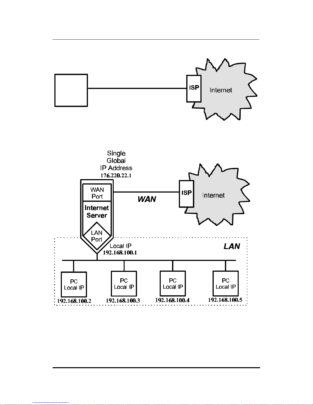
Internet Server Technology
The concept behind internet servers is to provide internet access
for multiple users through a single internet account. Without an
internet server, each end node (i.e., PC or workstation) on a LAN
must have it’s own public domain (global) IP address.
Internet Server User’s Guide
Introduction 3
176.220.22.1
PC
(single
end user)
Single Global
IP Address
Using an internet server allows a single global IP address to be
shared by multiple end nodes simultaneously.
In this implementation, it is only necessary to pay for a single
internet account even though many people will be able to use it.

Internet Server User’s Guide
4 Installation
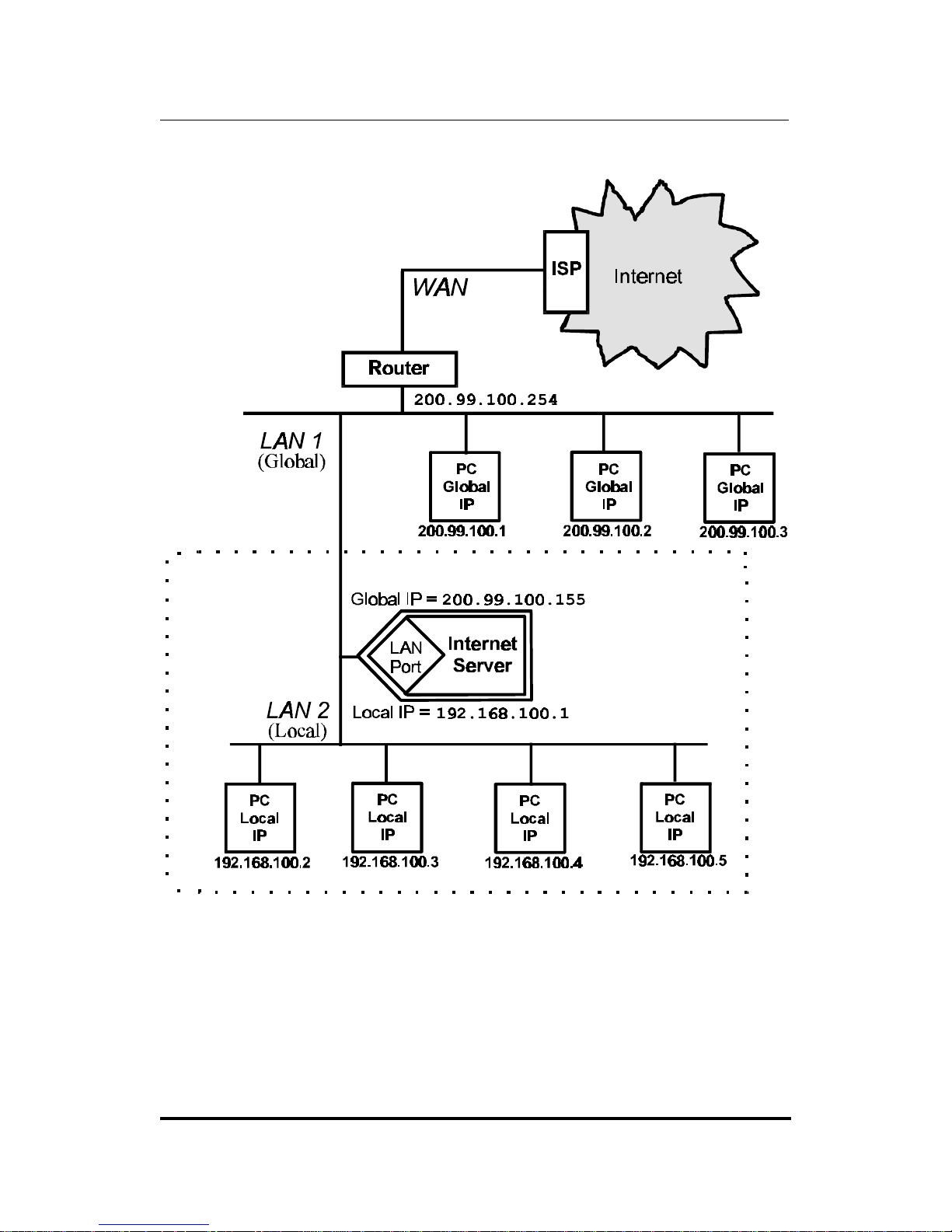
Non-Internet Implementations
An internet server can also be used to expand a LAN by creating a
localized IP “sub-group”. In this LAN-to-LAN configuration, the
internet server links the two IP subgroups (as shown below). This
implementation is useful when the LAN has run out of IP addresses. The internet server uses a single IP address from the first
(global) LAN to establish a second (local) LAN, in much the same
way it allows many users to connect to the internet through a single IP address. PC’s on the second LAN (called a local LAN since
the IP addresses of computers on this LAN are managed by the
internet server) can still access the internet by setting their
Gateway address to the IP address of the local LAN port of the
Internet server. Please note that the WAN ports on the DP-692
are disabled when it is operating in LAN-to-LAN mode.
Internet Server User’s Guide
Introduction 5


Internet Server User’s Guide
Installation 7
2
INSTALLATION
This chapter provides information on the unpacking and initial
installation of your internet server.
Unpacking
Open the shipping carton of your internet server and carefully
unpack the contents. The carton should contain the following
items:
♦ One internet server device
♦ One AC power adapter, suitable for your areas electrical
power connections
♦ One 3.5” diskette with IS Admin software
♦ IS Admin User’s Guide
♦ One 3.5” diskette with IS Manager Server software
♦ IS Manager Server User’s Guide
♦ One 3.5” diskette with IS Mail Server software
♦ IS Mail Server User’s Guide
♦ This User’s Guide

Internet Server User’s Guide
8 Installation
Inspect the device and all accompanying items. If any item is
damaged or missing, report the problem immediately to your
dealer.
Desktop / Shelf Installation
The unit has rubber feet attached to the bottom to cushion it. Allow enough ventilation space between the device and the objects
around it. Choose a sturdy, level surface in a ventilated area that
is dust free and away from heat vents, warm air exhaust from
other devices and direct sunlight. Avoid proximity to large electric motors or other electromagnetic equipment.
Observe the following guidelines when choosing an installation
location:
• Air temperature should range from 32° to 122° F (0° to 50° C).
• Humidity should be less than 90%, non-condensing.
• Site should not exceed the electromagnetic field standards for
IEC 801-3, Level 2 (3V/M) field strength.
For a detailed list of the product’s technical specifications, refer to
Appendix B, Specifications.
Port Descriptions

Internet Server User’s Guide
Installation 9
DP-692 Rear Panel
RJ-45 – LAN
The internet server has ten, 10BASE-T, RJ-45 LAN ports. These
MDI-X UTP ports are 10Mbps capable and designed for use in an
Ethernet LAN. By pressing the button next to the tenth port so
that it is in the OUT position, the port 10X will become an MDI-II
Uplink port for connecting the internet server to another hub.
BNC – LAN
The DP-692 provides a BNC port for cascading with other hubs
without sacrificing any RJ-45 ports. Use this port to connect to
your thin coax backbone.
DP-692 Side Panel
Serial – WAN
Serial ports are used for WAN connections either to a modem or
an ISDN terminal adapter. Both serial ports are standard male 9pin RS-232 connectors. The WAN ports can be set to operate between 4800bps and 460800bps.
Internet Server User’s Guide
10 Installation
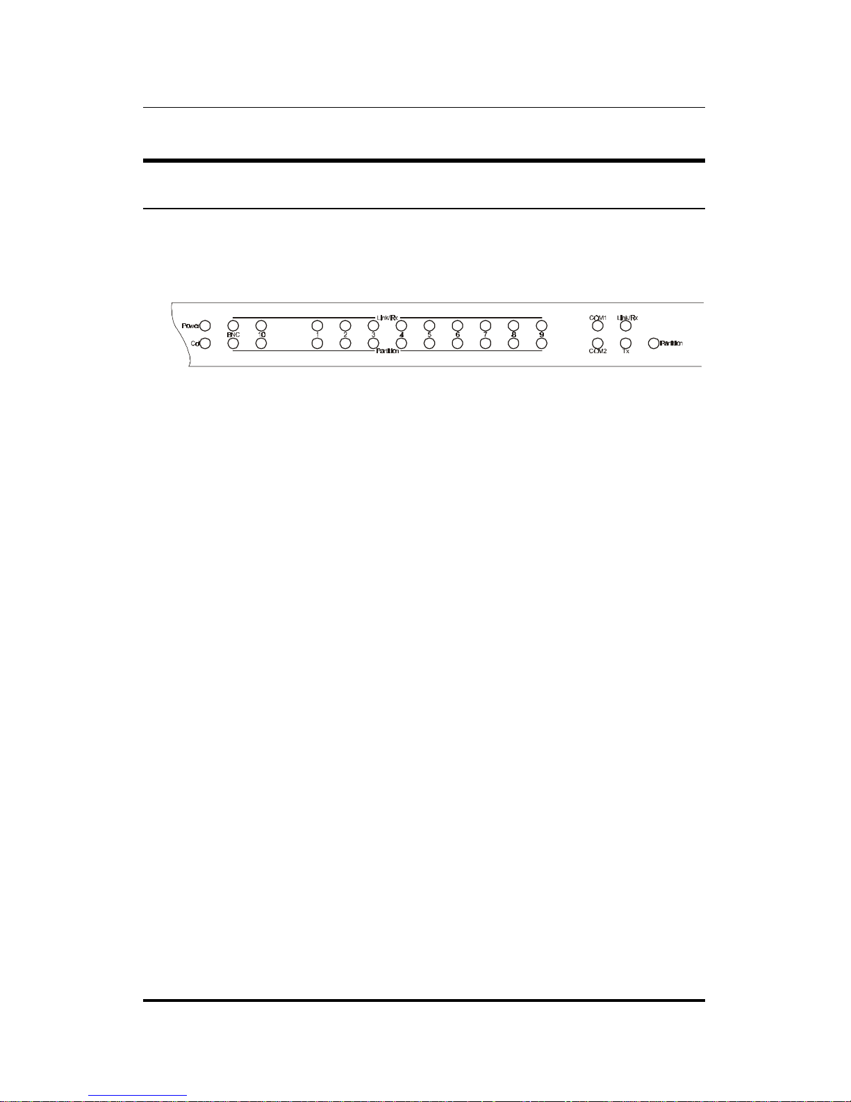
Diagnostic LED Descriptions
The internet server has an LED array for indicating current port
and transmission status and is shown below.
DP-692 Front Panel LEDs
• Power
◊ ON: “power good”.
◊ OFF: “power bad.” Check to see if the AC power adapter is
properly connected, or if the correct AC power adapter is
being used.
• Collision
◊ Blinking: Packet collision is occurring. Packet collisions
are not an abnormal situation. Collisions occur when two
or more computers transmit packets on the network simultaneously, and a contention takes place on the network
line. The computers should then back off, then retry
transmission. This trial-and-error process is repeated until
no collision takes place. Note: Excessive collisions may result when multiple hubs are cascaded through a thin
coaxial segment and many stations are connected on the
network.
◊ Off: No packet collision.
• Link/Rx (for each UTP port)

Internet Server User’s Guide
Installation 11
◊ ON: Data link between UTP port and host computer’s or
uplinked hub’s UTP port is successful.
◊ OFF: No data link or cable disconnected. Check for bad ca-
ble or loose connectors. For uplinked hubs, check to see if
UTP cable contains crossed-over wires. Also check for a
“power good” condition at both ends of the connection. If
you suspect that the hub port is damaged, contact your
authorized dealer for service.
◊ Blinking: Packet reception is occurring.
• Rx (for BNC port).
◊ Blinking: Packet reception is occurring.
◊ OFF: No packet reception.
• Partition (for each UTP port).
◊ ON: The UTP port is being partitioned off due to excessive
packet collisions. Note that the UTP cable between a hub
port and a non-repeater node must contain straightthrough wires (no cross-over).
◊ OFF: Segment has no problem.
• Partition (for BNC port).
◊ ON: The BNC port is being partitioned off due to (1) no ca-
ble is connected, (2) faulty cable or connectors, (3) excessive
packet collisions, (4) a disconnected point somewhere along
the entire thin coaxial cable length, or (5) unterminated
segment. Check all connectors along the cable length. If
segment is not terminated, terminate both ends with 50ohm terminators.
◊ OFF: (1) Cable is connected and (2) segment has no prob-
lem.

Internet Server User’s Guide
12 Installation
• COM1 / COM2
◊ ON: Each COM port LED provides an indication of the op-
erating status of the corresponding WAN port. When a
WAN port is transmitting data, the related COM port indicator will light.
◊ OFF: No data is being transmitted.
• Link/Rx (at far right)
◊ ON: The (internal) link between the Internet server’s LAN
and Hub circuits is OK.
◊ OFF: The link between the Internet server’s LAN and Hub
circuits is not working. If this condition persists, contact
your dealer for service.
◊ Blinking: The Internet server’s LAN is receiving packets
from the Hub.
• Tx (at far right)
◊ Blinking: The Internet server’s LAN is sending packets to
the unit’s Hub circuitry.
◊ OFF: The Internet server’s LAN is not sending packets to
the Hub circuitry.
• Partition (at far right)
◊ ON: The Internet server’s LAN circuitry has been parti-
tioned, that is, cut off from the Hub circuitry, probably due
to excessive collisions or a hardware problem. If this condition persists, contact your dealer for service.
◊ OFF: The Internet server’s LAN circuitry is not partitioned.

Internet Server User’s Guide
Installation 13
Normal LED Flash Pattern
Immediately after power-up, both COM LEDs should display
steady green for several seconds. Then both COM LEDs should
flash simultaneously three times. This sequence of flashes should
be followed by first COM1 flashing once and then COM2 flashing
once, repeated three times in succession. If as problem with the
device is detected during this time, the LED flashes will display
an error pattern (see Appendix A: Troubleshooting for more information on POST error indications). If no errors are detected,
the internet server will begin operating normally.
Connecting to the Local Network
This section describes how to connect the DP-692 internet server
to your Ethernet network.
Cables
• The EIA/TIA 568 Wiring Standard imposes a 100 me-
ter limit on horizontal runs of twisted-pair cables; in
this case, from the internet server to any other device.
• 10 Mbps Ethernet connections must use Category 3 or
better twisted-pair cabling fitted with RJ-45 connectors.
• Cat 5 UTP cables use the same RJ-45 connector used
with 10BASE-T, wired in the same configuration.
Connecting to a Twisted-Pair LAN
As mentioned before, the internet server comes equipped with ten
Ethernet RJ-45 LAN ports. Together, these twisted-pair ports
function as a normal Ethernet hub. To connect the internet server
to an existing 10BASE-T LAN, simply plug one end of a straight-
 Loading...