

Page 1

DGS-3024
Layer 2 Switch
Command Line Interface Reference Manual
First Edition (December 2004)
6DGS3024C.01
Printed In Taiwan
RECYCLABLE
Page 2

Table of Contents
Introduction...................................................................................................................................................................................... 1
Using the Console CLI..................................................................................................................................................................... 4
Command Syntax ............................................................................................................................................................................. 9
Basic Switch Commands................................................................................................................................................................ 11
Switch Port Commands.................................................................................................................................................................. 23
Network Management (SNMP) Commands .................................................................................................................................. 25
MAC Notification Commands ....................................................................................................................................................... 47
Download/Upload Commands ....................................................................................................................................................... 51
Network Monitoring Commands.................................................................................................................................................... 54
Spanning Tree Commands ............................................................................................................................................................. 66
Forwarding Database Commands .................................................................................................................................................. 72
Broadcast Storm Control Commands............................................................................................................................................. 78
QoS Commands.............................................................................................................................................................................. 80
Port Mirroring Commands ............................................................................................................................................................. 86
VLAN Commands.......................................................................................................................................................................... 89
Link Aggregation Commands ........................................................................................................................................................ 95
Basic IP Commands ....................................................................................................................................................................... 99
IGMP Snooping Commands ........................................................................................................................................................ 101
802.1X Commands....................................................................................................................................................................... 108
Time and SNTP Commands......................................................................................................................................................... 120
Routing Table Commands............................................................................................................................................................ 126
ARP Commands........................................................................................................................................................................... 128
Command History List................................................................................................................................................................. 132
Technical Specifications .............................................................................................................................................................. 136
Page 3
DGS-3024 Layer 2 Switch CLI Reference Manual
1
INTRODUCTION
The DGS-3024 Switch can be managed through the Switch’s serial port, Telnet, or the Web-based management agent. The
Command Line Interface (CLI) can be used to configure and manage the Switch via the serial port or Telnet interfaces.
This manual provides a reference for all of the commands contained in the CLI. Configuration and management of the Switch
via the Web-based management agent is discussed in the User’s Guide.
Accessing the Switch via the Serial Port
The Switch’s serial port’s default settings are as follows:
• 9600 baud
• no parity
• 8 data bits
• 1 stop bit
A computer running a terminal emulation program capable of emulating a VT-100 terminal and a serial port configured as
above is then connected to the Switch’s serial port via an RS-232 DB-9 cable.
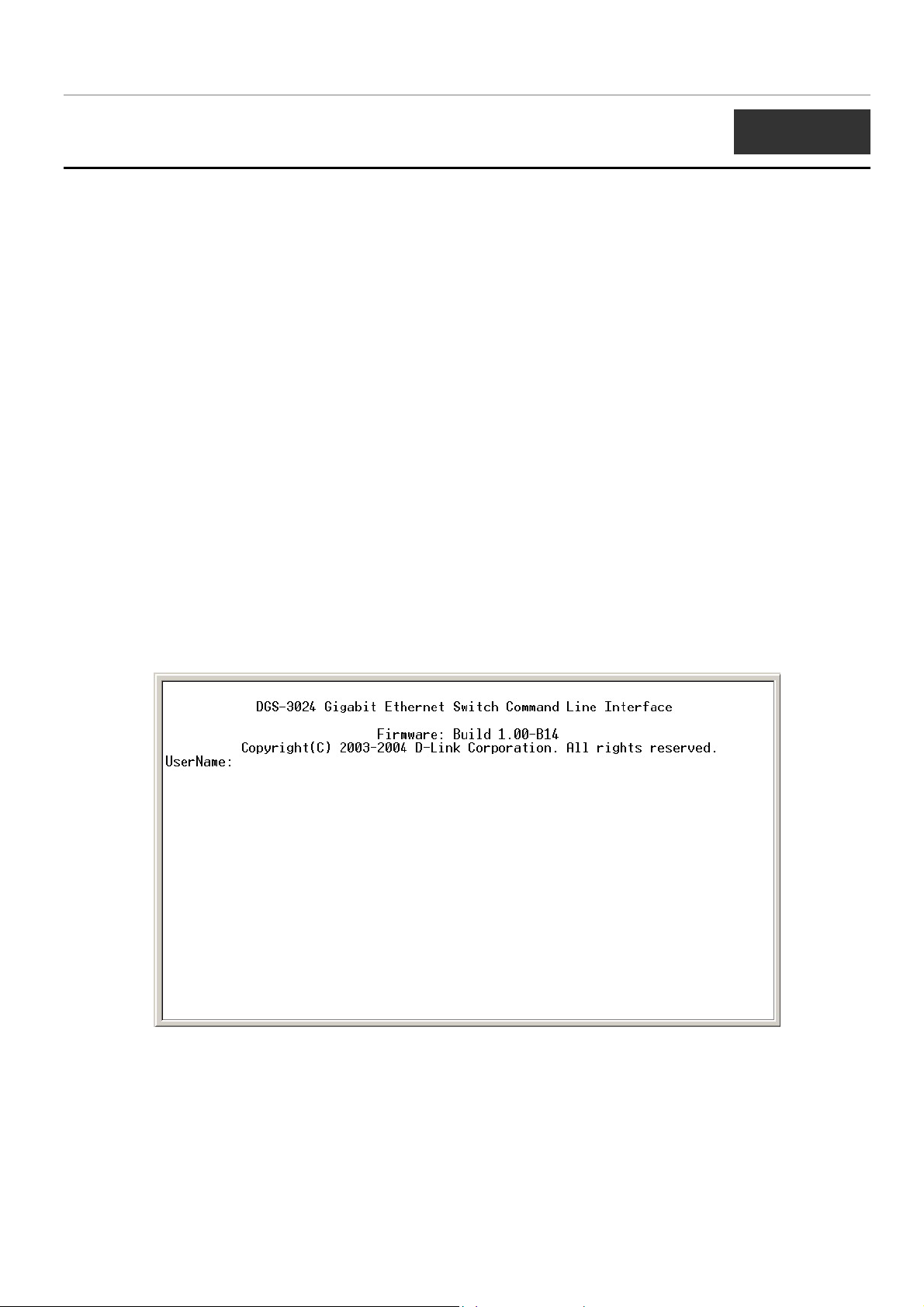
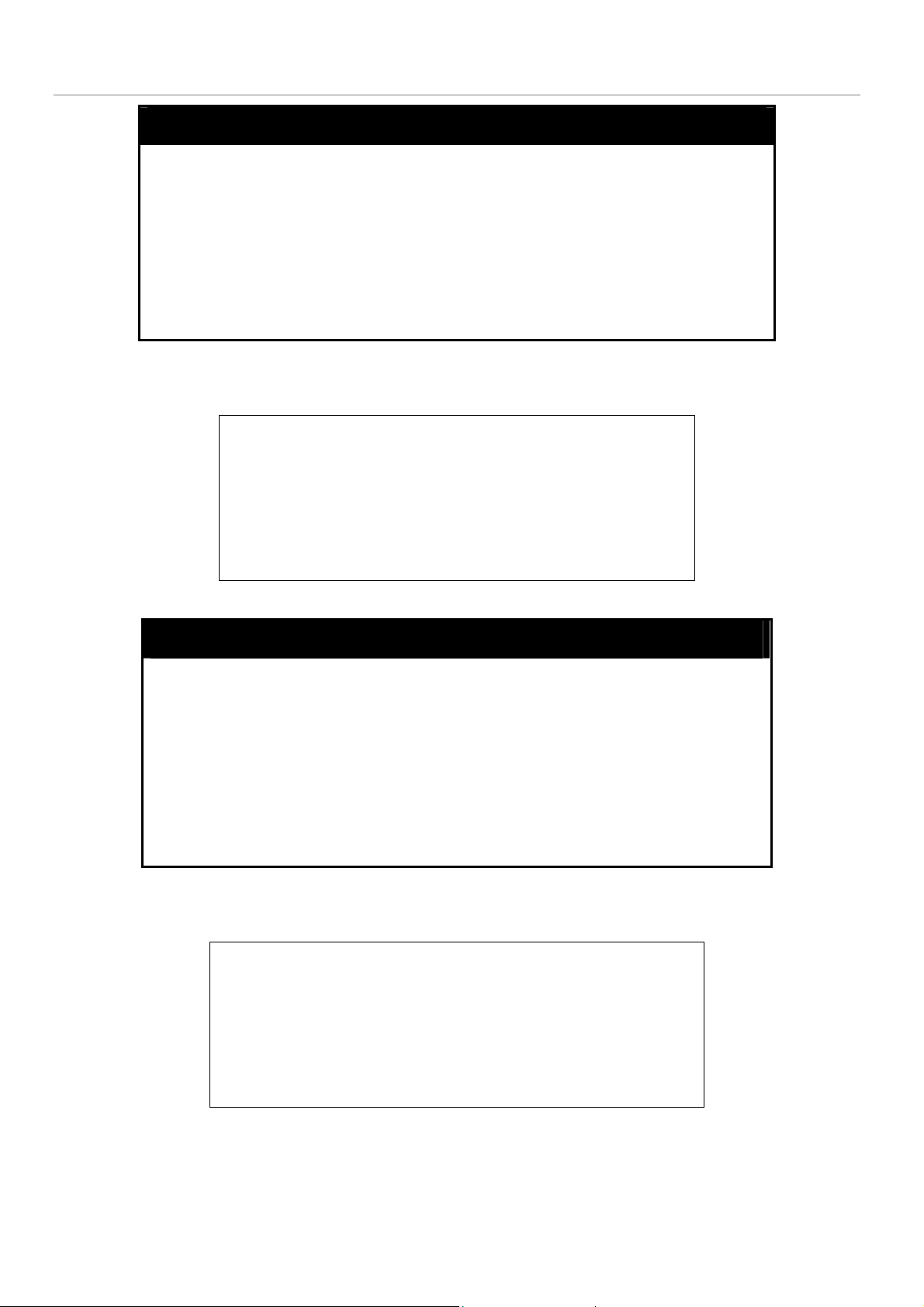
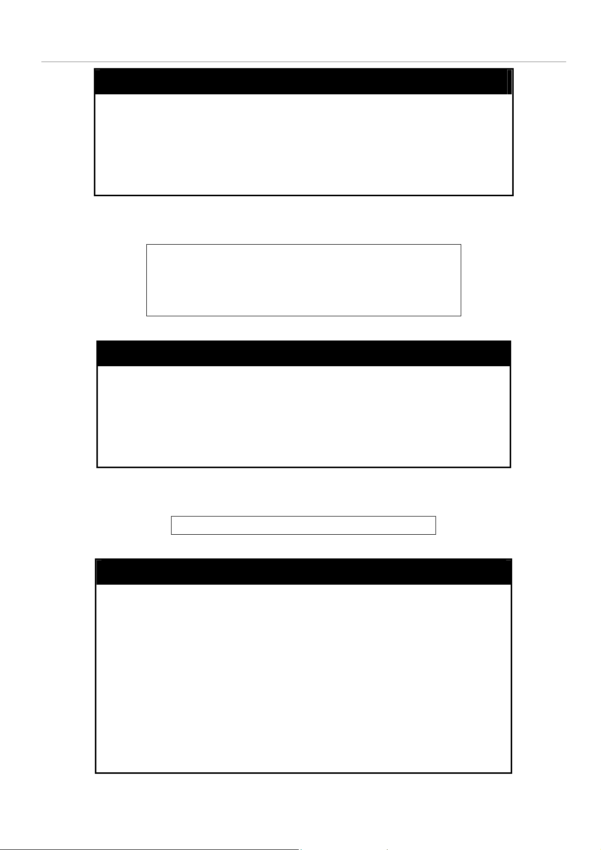
With the serial port properly connected to a management computer, the following screen should be visible. If this screen does
not appear, try pressing Ctrl+r to refresh the console screen.
Figure 1-1. Initial CLI screen
There is no initial username or password. Just press the Enter key twice to display the CLI input cursor − DGS-3024:4#. This is
the command line where all commands are input.
1
Page 4
DGS-3024 Layer 2 Switch CLI Reference Manual
Setting the Switch’s IP Address
Each switch must be assigned its own IP Address, which is used for communication with an SNMP network manager or other
TCP/IP application (for example BOOTP, TFTP). The Switch’s default IP address is 10.90.90.90. You can change the default
Switch IP address to meet the specification of your networking address scheme.
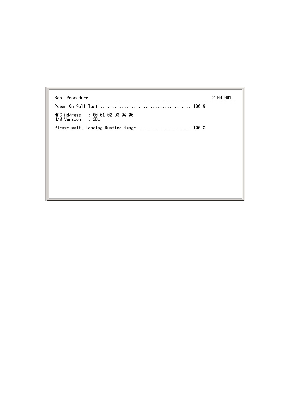
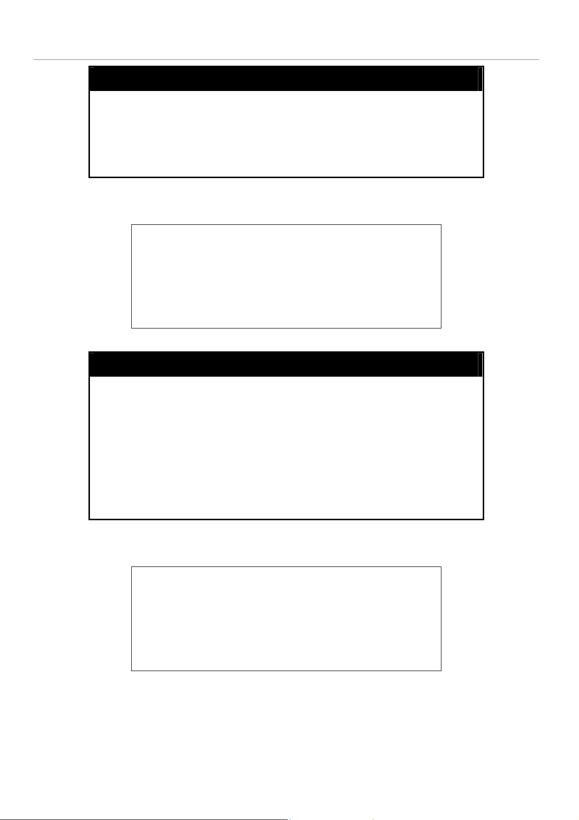
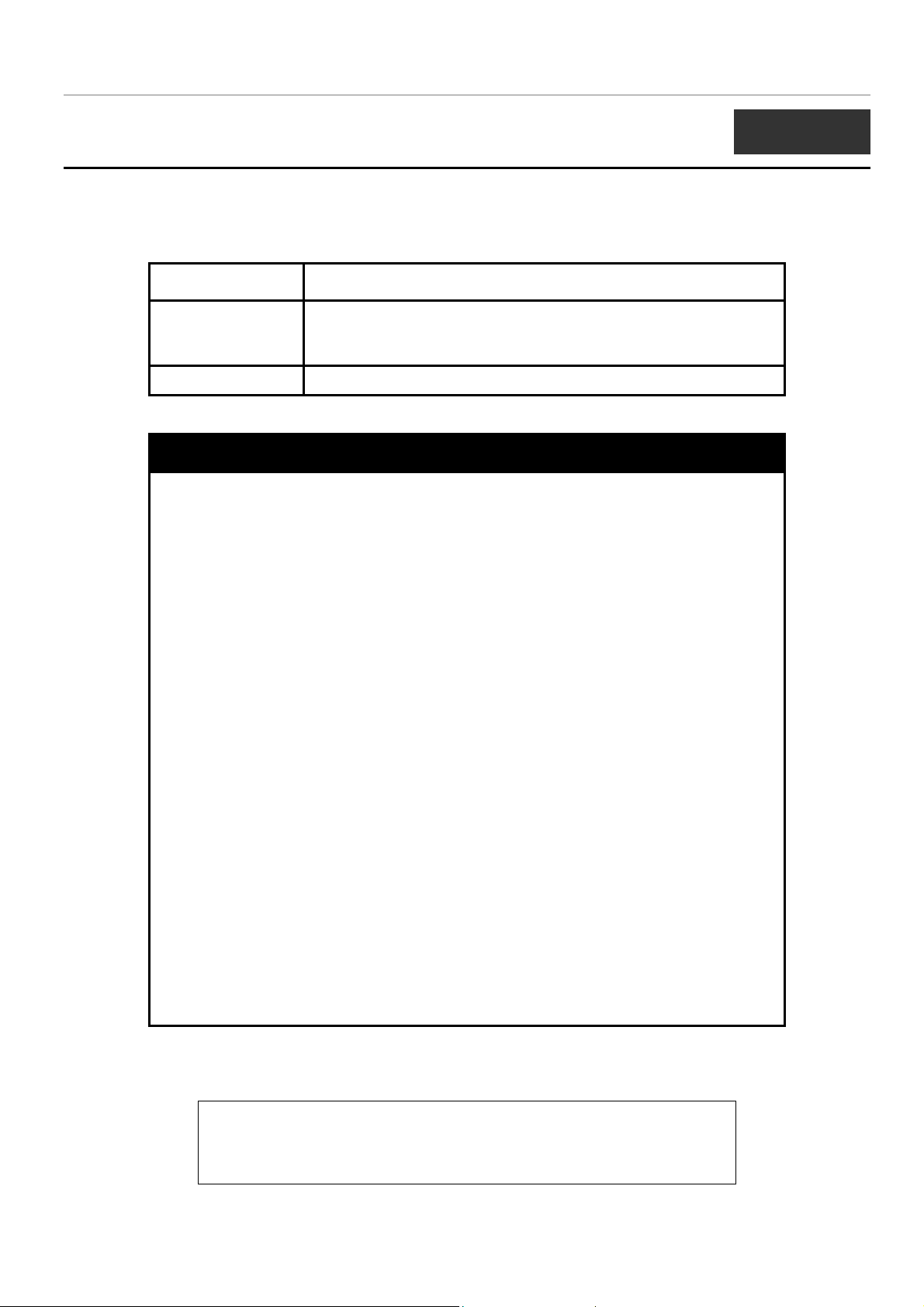
The Switch is also assigned a unique MAC address by the factory. This MAC address cannot be changed, and can be found on
the initial boot console screen – shown below.
Figure 1-2. Boot Screen
The Switch’s MAC address can also be found in the Web management program on the Switch Information (Basic Settings)
window on the Configuration menu.
The IP address for the Switch must be set before it can be managed with the Web-based manager. The Switch IP address can be
automatically set using BOOTP or DHCP protocols, in which case the actual address assigned to the Switch must be known.
The IP address may be set using the Command Line Interface (CLI) over the console serial port as follows:
1. Starting at the command line prompt, enter the commands config ipif System ipaddress
xxx.xxx.xxx.xxx/yyy.yyy.yyy.yyy. Where the x’s represent the IP address to be assigned to the IP interface named
System and the y’s represent the corresponding subnet mask.
2. Alternatively, you can enter config ipif System ipaddress xxx.xxx.xxx.xxx/z. Where the x’s represent the IP address
to be assigned to the IP interface named System and the z represents the corresponding number of subnets in CIDR
notation.
The IP interface named System on the Switch can be assigned an IP address and subnet mask which can then be used to connect
a management station to the Switch’s Telnet or Web-based management agent.
2
Page 5
DGS-3024 Layer 2 Switch CLI Reference Manual
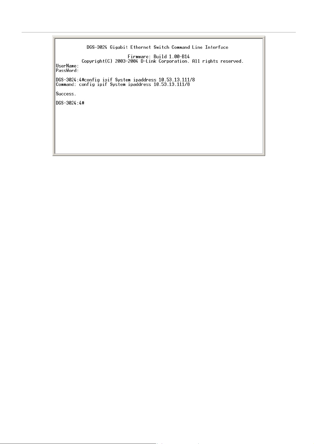
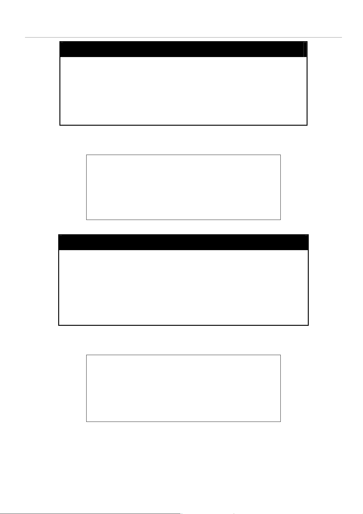
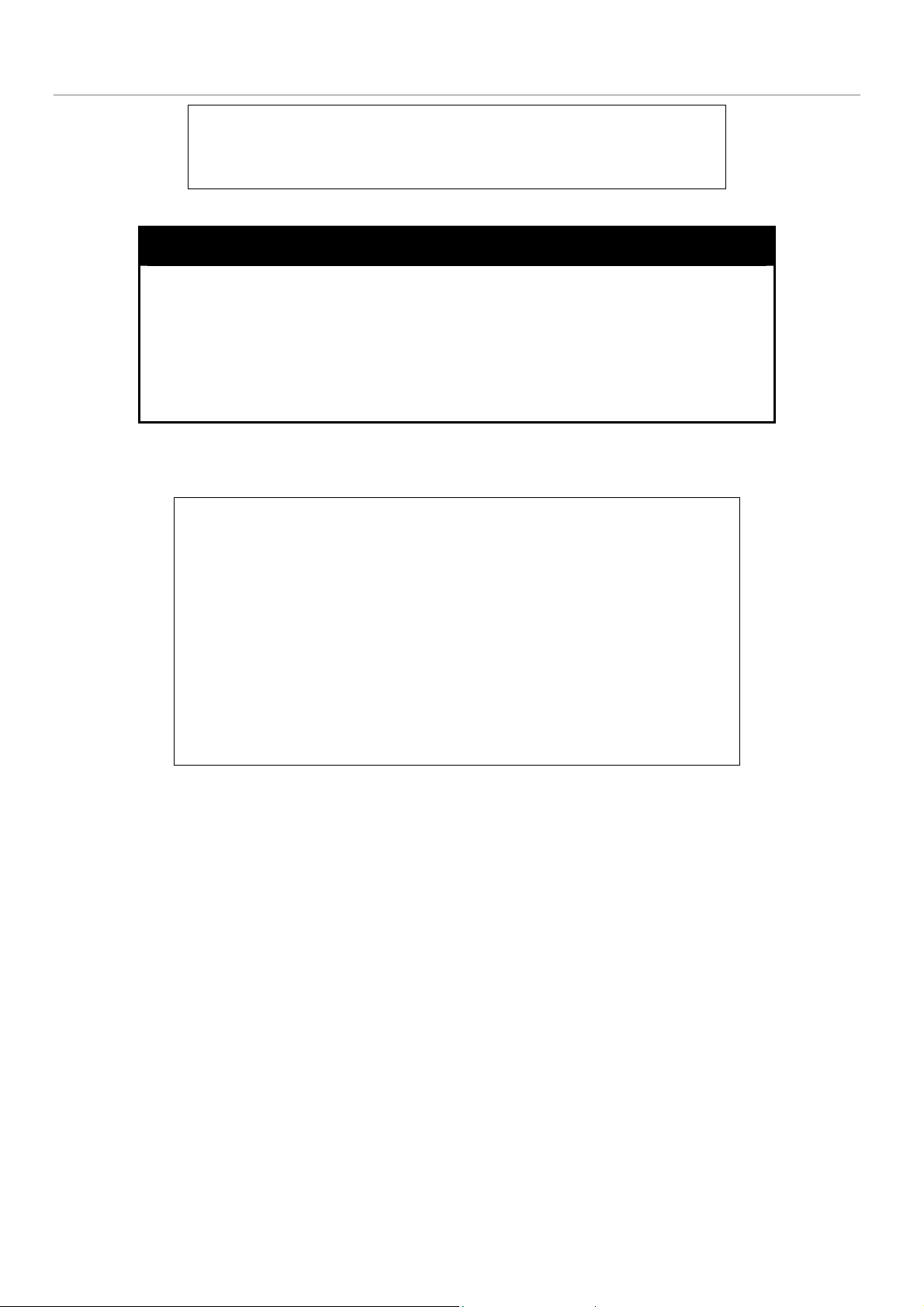
Figure 1-3. Assigning an IP Address
In the above example, the Switch was assigned an IP address of 10.53.13.111 with a subnet mask of 255.0.0.0 (8 in CIDR
from). The system message Success indicates that the command was executed successfully. The Switch can now be configured
and managed via Telnet and the CLI or via the Web-based management agent using the above IP address to connect to the
Switch.
3
Page 6

DGS-3024 Layer 2 Switch CLI Reference Manual
2
USING THE CONSOLE CLI
The DGS-3024 supports a console management interface that allows the user to connect to the Switch’s management agent via a
serial port and a terminal or a computer running a terminal emulation program. The console can also be used over the network
using the TCP/IP Telnet protocol. The console program can be used to configure the Switch to use an SNMP-based network
management software over the network.
This chapter describes how to use the console interface to access the Switch, change its settings, and monitor its operation.
Note: Switch configuration settings are saved to non-volatile RAM using the
save command. The current configuration will then be retained in the
Switch’s NV-RAM, and reloaded when the Switch is rebooted. If the Switch
is rebooted without using the save command, the last configuration saved to
NV-RAM will be loaded.
Connecting to the Switch
The console interface is used by connecting the Switch to a VT100-compatible terminal or a computer running an ordinary
terminal emulator program (e.g., the HyperTerminal program included with the Windows operating system) using an RS-232C
serial cable. Your terminal parameters will need to be set to:
• VT-100 compatible
• 9,600 baud
• 8 data bits
• No parity
• One stop bit
• No flow control
You can also access the same functions over a Telnet interface. Once you have set an IP address for your Switch, you can use a
Telnet program (in VT-100 compatible terminal mode) to access and control the Switch. All of the screens are identical,
whether accessed from the console port or from a Telnet interface.
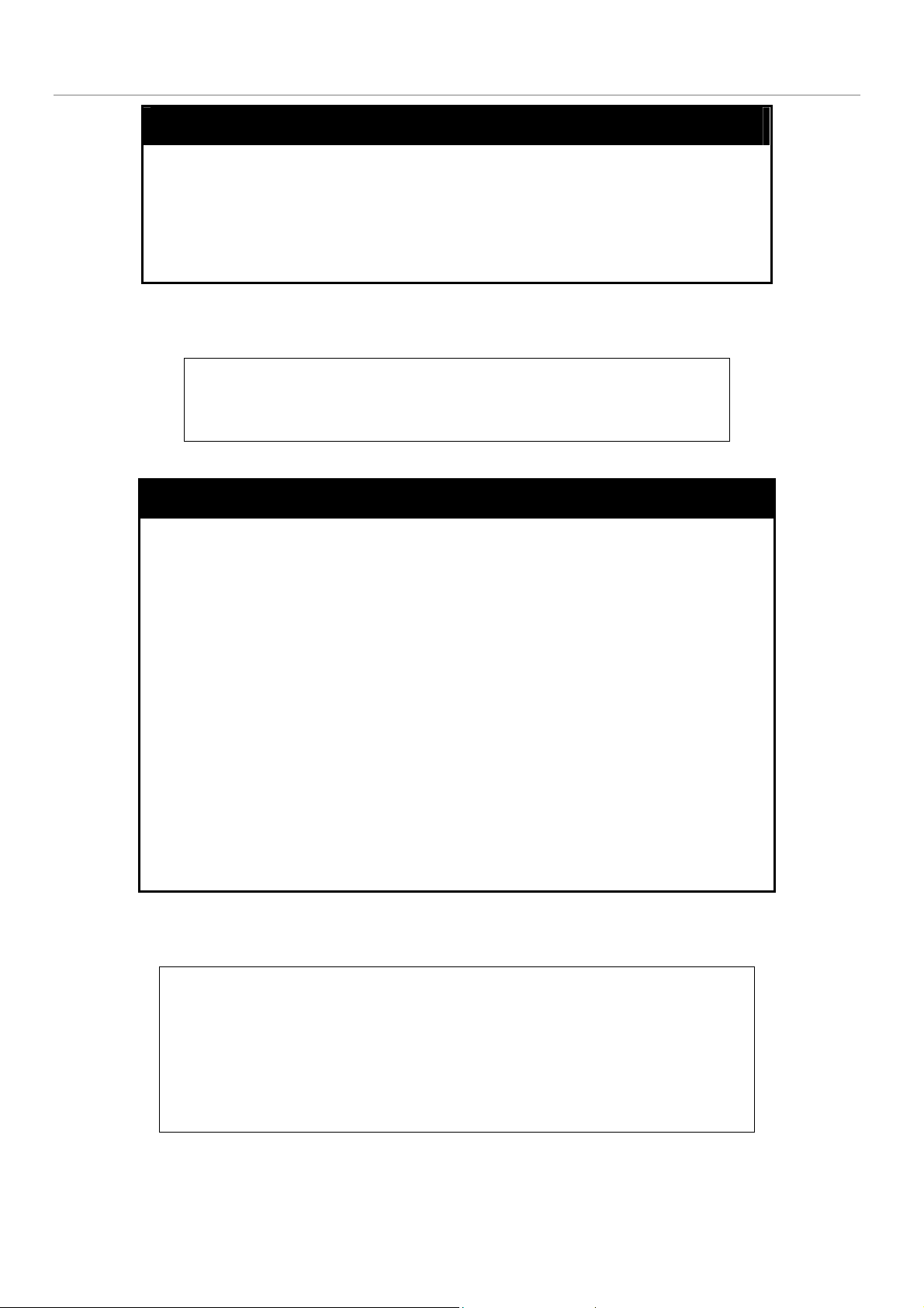
After the Switch reboots and you have logged in, the console looks like this:
4
Page 7
DGS-3024 Layer 2 Switch CLI Reference Manual
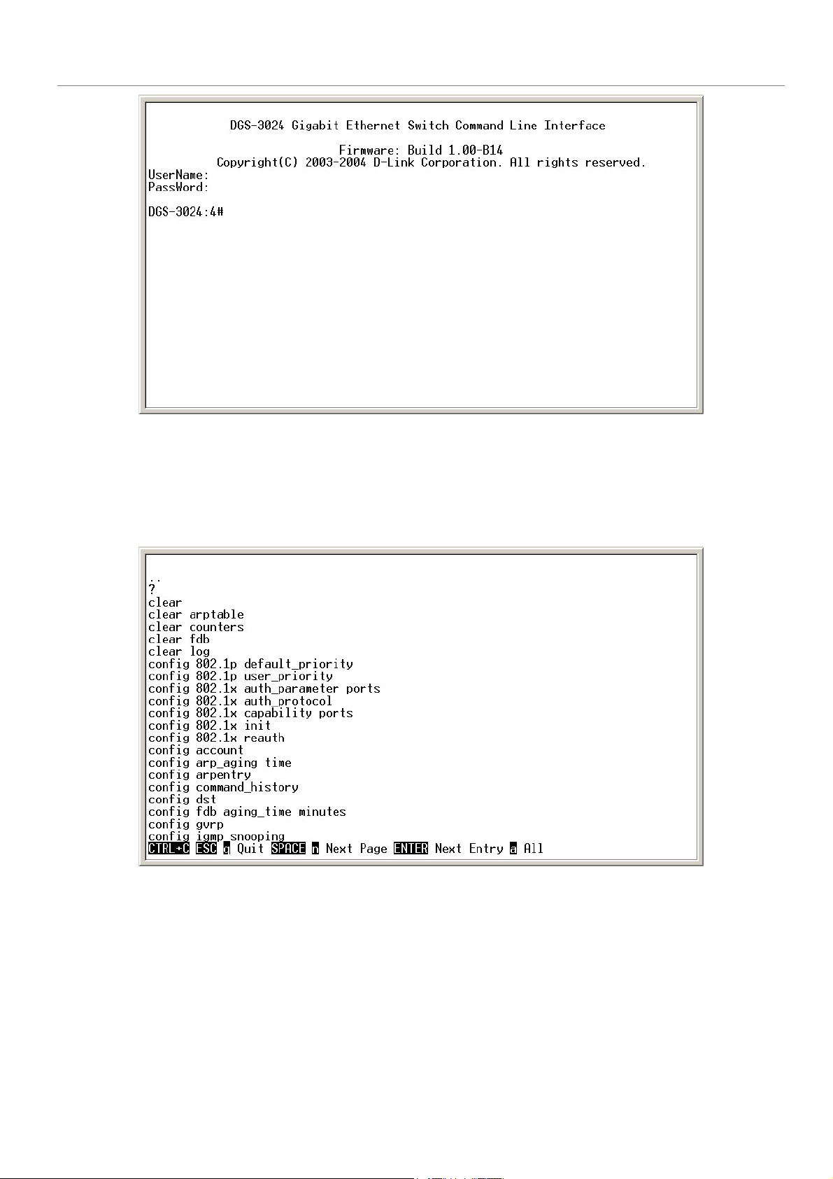
Figure 2-1. Console Screen after login
Commands are entered at the command prompt, DGS-3024:4#.
There are a number of helpful features included in the CLI. Entering the ? command will display a list of all of the top-level
commands.
Figure 2-2. The ? Command
The dir command has the same function as the ? command.
When you enter a command without its required parameters, the CLI will prompt you with a Next possible completions:
message.
5
Page 8
DGS-3024 Layer 2 Switch CLI Reference Manual
Figure 2-3. Example Command Parameter Help
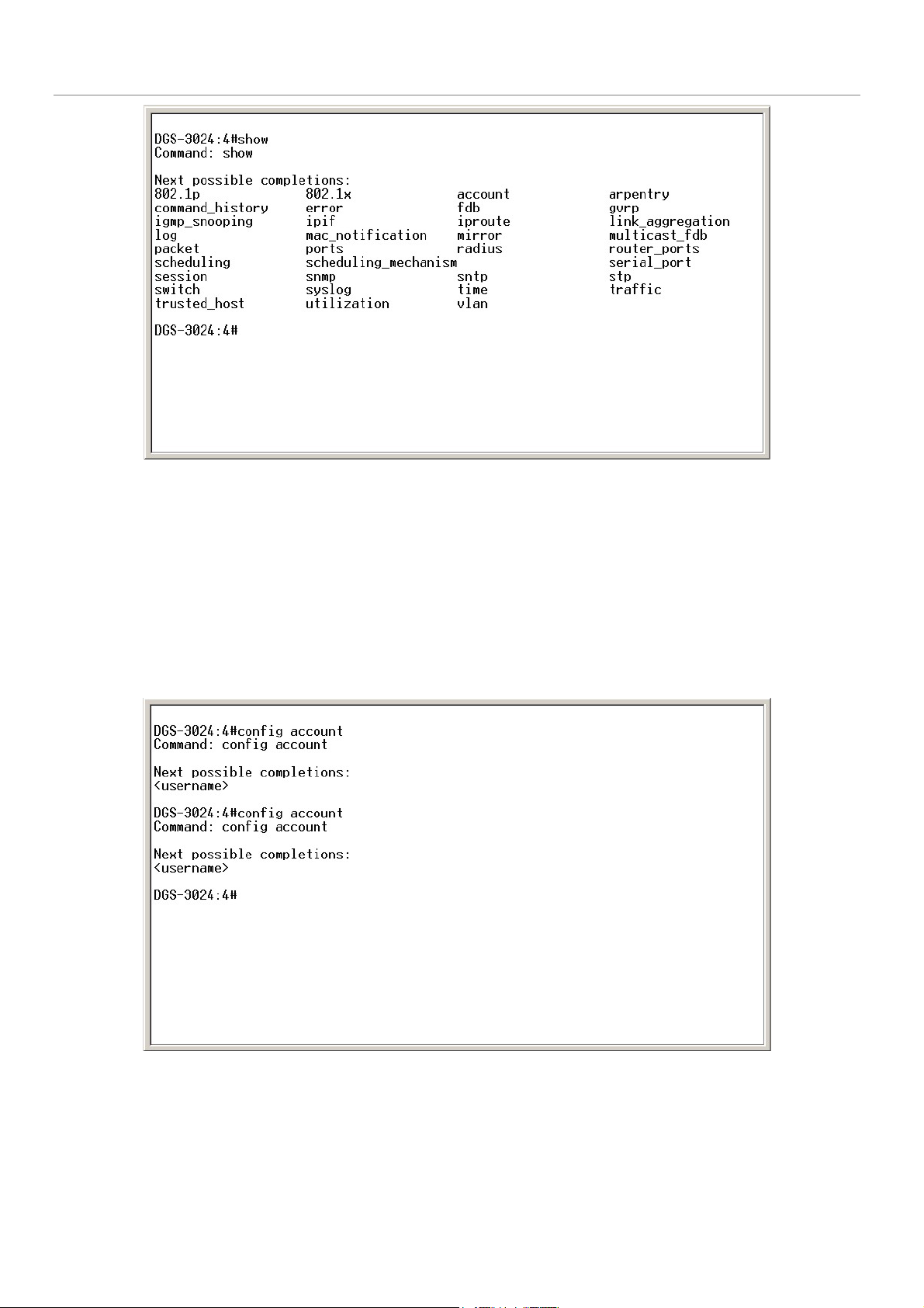
In this case, the command show was entered without a parameter. The CLI will then prompt you to enter the next possible
completions with the message, Next possible completions:. Every command in the CLI has this feature, and complex
commands have several layers of parameter prompting.
In addition, after typing any given command plus one space, you can see all of the next possible sub-commands, in sequential
order, by repeatedly pressing the Tab key.
To re-enter a previously entered command at the command prompt, press the up arrow cursor key. The previous command will
appear at the command prompt.
Figure 2-4. Using the Up Arrow to Re-enter a Command
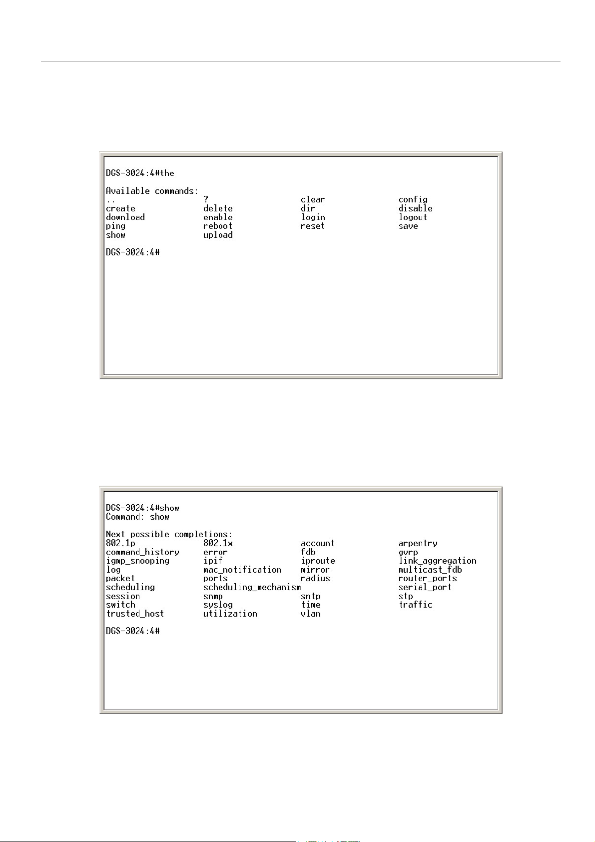
In the above example, the command config account was entered without the required parameter <username>, the CLI returned
the Next possible completions: <username> prompt. The up arrow cursor control key was pressed to re-enter the previous
command (config account) at the command prompt. Now the appropriate user name can be entered and the config account
command re-executed.
6
Page 9
DGS-3024 Layer 2 Switch CLI Reference Manual
All commands in the CLI function in this way. In addition, the syntax of the help prompts are the same as presented in this
manual − angle brackets < > indicate a numerical value or character string, braces { } indicate optional parameters or a choice of
parameters, and brackets [ ] indicate required parameters.
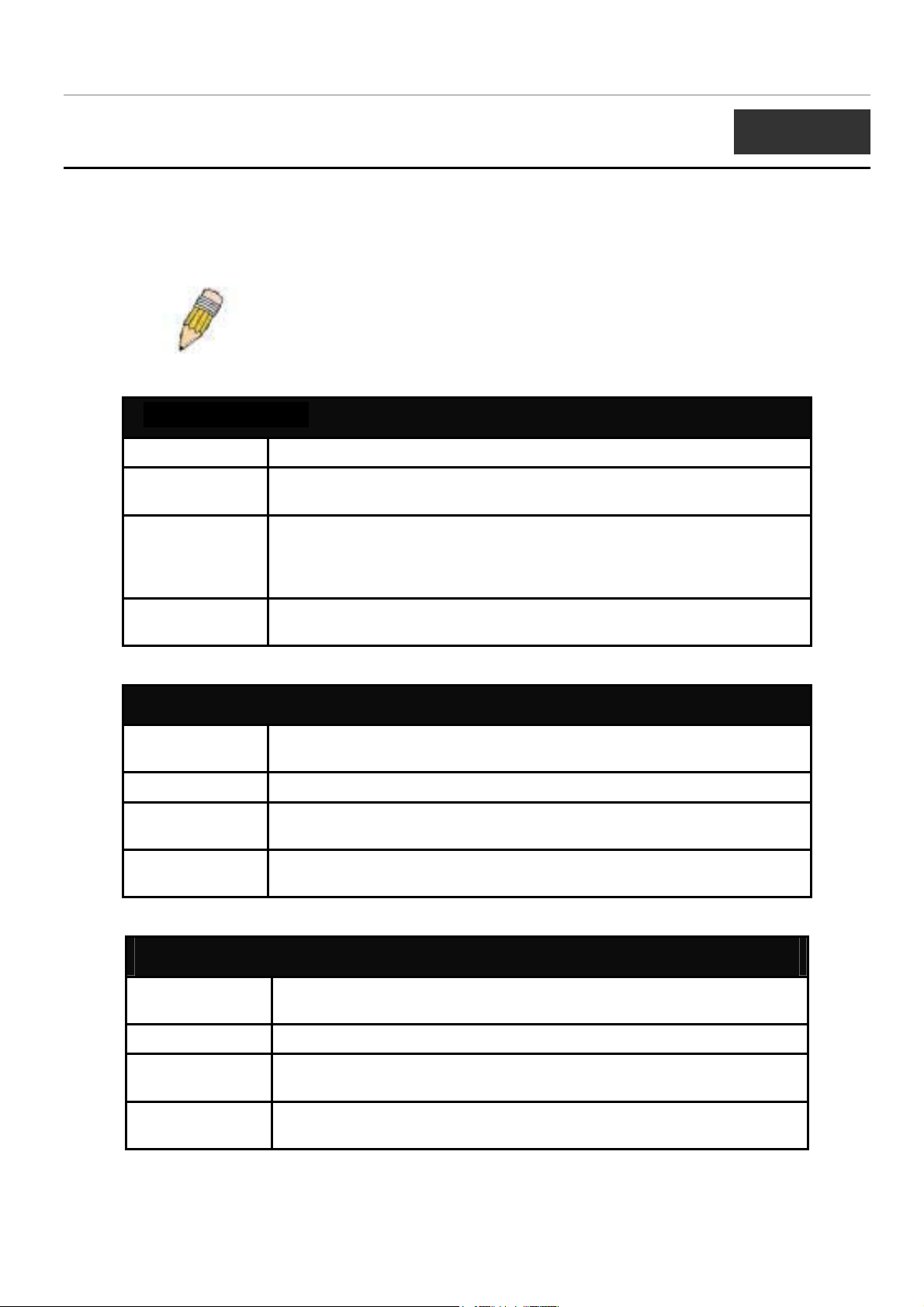
If a command is entered that is unrecognized by the CLI, the top-level commands will be displayed under the Available
commands: prompt.
Figure 2-5. The Next Available Commands Prompt
The top-level commands consist of commands such as show or config. Most of these commands require one or more parameters
to narrow the top-level command. This is equivalent to show what? or config what? Where the what? is the next parameter.
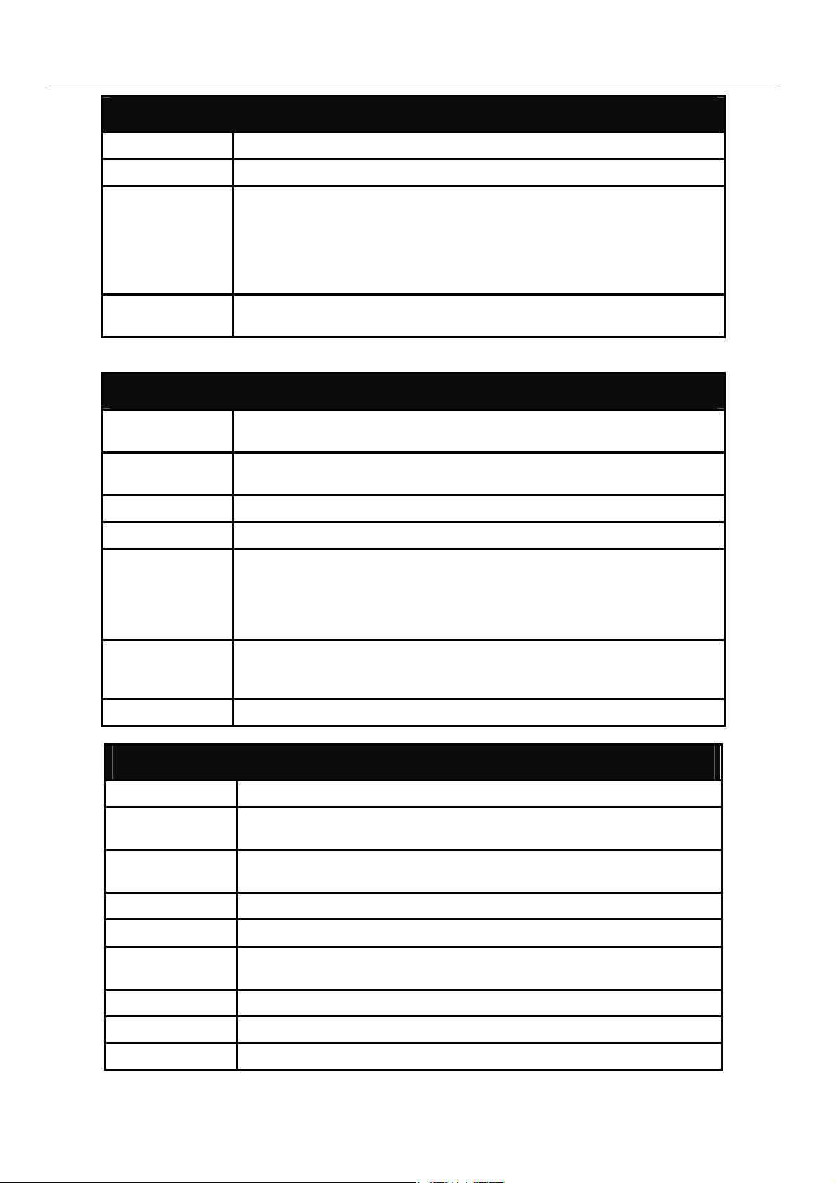
For example, if you enter the show command with no additional parameters, the CLI will then display all of the possible next
parameters.
Figure 2-6. Next possible completions: show command
7
Page 10

DGS-3024 Layer 2 Switch CLI Reference Manual
In the above example, all of the possible next parameters for the show command are displayed. At the next command prompt,
the up arrow was used to re-enter the show command, followed by the account parameter. The CLI then displays the user
accounts configured on the Switch.
8
Page 11
DGS-3024 Layer 2 Switch CLI Reference Manual
3
COMMAND SYNTAX
The following symbols are used to describe how command entries are made and values and arguments are specified in this
manual. The online help contained in the CLI and available through the console interface uses the same syntax.
Note: All commands are case-sensitive. Be sure to disable Caps Lock or
any other unwanted function that changes text case.
<angle brackets>
Purpose Encloses a variable or value that must be specified.
Syntax
Description In the above syntax example, you must supply an IP interface name in the
Example
Command
create ipif <ipif_name> vlan <vlan_name 32> ipaddress
<network_address>
<ipif_name> space, a VLAN name in the <vlan_name 32> space, and the
network address in the <network_address> space. Do not type the angle
brackets.
create ipif Engineering vlan Design ipaddress 10.24.22.5/255.0.0.0
[square brackets]
Purpose Encloses a required value or set of required arguments. One value or
argument can be specified.
Syntax
Description
Example
Command
create account [admin | user]
In the above syntax example, you must specify either an admin or a user
level account to be created. Do not type the square brackets.
create account admin
| vertical bar
Purpose Separates two or more mutually exclusive items in a list, one of which must
be entered.
Syntax
Description
Example
Command
show snmp [community | detail]
In the above syntax example, you must specify either community, or
detail. Do not type the vertical bar.
show snmp community
9
Page 12
DGS-3024 Layer 2 Switch CLI Reference Manual
{braces}
Purpose Encloses an optional value or set of optional arguments.
Syntax
Description
Example
command
reset {[config | system]}
In the above syntax example, you have the option to specify config or
system. It is not necessary to specify either optional value, however the
effect of the system reset is dependent on which, if any, value is specified.
Therefore, with this example there are three possible outcomes of
performing a system reset. See the chapter Basic Commands for more
details about the reset command.
reset config
Line Editing Key Usage
Delete Deletes the character under the cursor and then shifts the remaining
characters in the line to the left.
Backspace Deletes the character to the left of the cursor and shifts the remaining
characters in the line to the left.
Left Arrow Moves the cursor to the left.
Right Arrow Moves the cursor to the right.
Up Arrow Repeat the previously entered command. Each time the up arrow is
pressed, the command previous to that displayed appears. This way it is
possible to review the command history for the current session. Use the
down arrow to progress sequentially forward through the command history
list.
Down Arrow The down arrow will display the next command in the command history
entered in the current session. This displays each command sequentially as
it was entered. Use the up arrow to review previous commands.
Tab Shifts the cursor to the next field to the left.
Multiple Page Display Control Keys
Space Displays the next page.
CTRL+c Stops the display of remaining pages when multiple pages are to be
displayed.
ESC Stops the display of remaining pages when multiple pages are to be
displayed.
n Displays the next page.
p Displays the previous page.
q Stops the display of remaining pages when multiple pages are to be
displayed.
r Refreshes the pages currently displayed.
a Displays the remaining pages without pausing between pages.
Enter Displays the next line or table entry.
10
Page 13
DGS-3024 Layer 2 Switch CLI Reference Manual
4
BASIC SWITCH COMMANDS
The basic switch commands in the Command Line Interface (CLI) are listed (along with the appropriate parameters) in the
following table.
Command Parameters
create account [admin | user] <username 15>
config account <username>
show account
show session
show switch
show serial_port
config serial_port {baud_rate [9600 | 19200 | 38400 | 115200] auto_logout [never |
2_minutes | 5_minutes| 10_minutes | 15_minutes]}
enable clipaging
disable clipaging
enable telnet <tcp_port_number 1-65535>
disable telnet
enable web <tcp_port_number 1-65535>
disable web
save
reboot
reset {[config | system]}
login
logout
ping <ipaddr> {times <value 1-255>} {timeout <sec 1-99>}
Each command is listed, in detail, in the following sections.
create account
Purpose Used to create user accounts.
Syntax
create [admin | user] <username 15>
Description The create account command is used to create user accounts that
consist of a username of 1 to 15 characters and a password of 0 to
15 characters. Up to 8 user accounts can be created.
Parameters admin <username>
user <username>
Restrictions Only Administrator-level users can issue this command.
Usernames can be between 1 and 15 characters.
11
Page 14
Example usage:
To create an administrator-level user account with the username “dlink”.
DGS-3024 Layer 2 Switch CLI Reference Manual
create account
Passwords can be between 0 and 15 characters.
DGS-3024:4#create account admin dlink
Command: create account admin dlink
Enter a case-sensitive new password:****
Enter the new password again for confirmation:****
Success.
DGS-3024:4#
config account
Purpose Used to configure user accounts.
Example usage:
To configure the user password of “dlink” account:
Syntax
Description The config account command configures a user account that has
Parameters <username>
Restrictions Only Administrator-level users can issue this command.
DGS-3024:4#config account dlink
Command: config account dlink
Enter a old password:****
Enter a case-sensitive new password:****
Enter the new password again for confirmation:****
Success.
config account <username>
been created using the create account command.
Usernames can be between 1 and 15 characters.
Passwords can be between 0 and 15 characters.
DGS-3024:4#
show account
Purpose Used to display user accounts.
Syntax
show account
12
Page 15
Example usage:
To display the accounts that have been created:
DGS-3024 Layer 2 Switch CLI Reference Manual
show account
Description Displays all user accounts created on the Switch. Up to 8 user
accounts can exist on the Switch at one time.
Parameters None.
Restrictions None.
DGS-3024:4#show account
Command: show account
Current Accounts:
Username Access Level
--------------- -----------dlink Admin
Total Entries: 1
Example usage:
To delete the user account “System”:
DGS-3024:4#
delete account
Purpose Used to delete an existing user account.
Syntax
Description The delete account command deletes a user account that has been
Parameters <username>
Restrictions Only Administrator-level users can issue this command.
DGS-3024:4#delete account System
Command: delete account System
Are you sure to delete the last administrator account?(y/n)
Success.
delete account <username>
created using the create account command.
DGS-3024:4#
13
Page 16

DGS-3024 Layer 2 Switch CLI Reference Manual
show session
Purpose Used to display a list of currently logged-in users.
Example usage:
To display the way that the users logged in:
show switch
Syntax
Description This command displays a list of all the users that are logged-in at
Parameters None.
Restrictions None.
DGS-3024:4#show session
Command: show session
ID Login Time Live Time From Level Name
-- --------------------------- --------------- -------------- ------- -------------------
*8 2204/01/26 3:36:27 0:0:20.260 Serial Port 4 Anonymous
CTRL+C ESC q Quit SPACE n Next Page p Previous Page r Refresh
show session
the time the command is issued.
Purpose Used to display information about the Switch.
Syntax
Description This command displays information about the Switch.
Parameters None.
Restrictions None.
Example usage:
To display the Switch information:
show switch
DGS-3024:4#show switch
Command: show switch
Device Type : DGS-3024 Gigabit-Ethernet Switch
MAC Address : DA-10-21-00-00-01
IP Address : 10.41.44.22 (Manual)
VLAN Name : default
Subnet Mask : 255.0.0.0
Default Gateway : 0.0.0.0
Boot PROM Version : Build 2.00.004
Firmware Version : Build 1.00-B14
Hardware Version : 0A1
System Name : DGS-3024_#3
System Location : 7th_flr_east_cabinet
System Contact : Julius_Erving_212-555-6666
Spanning Tree : Disabled
GVRP : Disabled
14
Page 17
DGS-3024 Layer 2 Switch CLI Reference Manual
IGMP Snooping : Disabled
TELNET : Enabled (TCP 23)
WEB : Enabled (TCP 80)
RMON : Enabled
DGS-3024:4#
show serial_port
Purpose Used to display the current serial port settings.
Example usage:
To display the serial port setting:
Syntax
Description This command displays the current serial port settings.
Parameters None.
Restrictions None.
DGS-3024:4#show serial_port
Command: show serial_port
Baud Rate : 9600
Data Bits : 8
Parity Bits : None
Stop Bits : 1
Auto-Logout : 10 mins
DGS-3024:4#
show serial_port
config serial_port
Purpose Used to configure the serial port.
Syntax
Description
Parameters
config serial_port {baud_rate [9600 | 19200 | 38400 | 115200] |
auto_logout [never | 2_minutes | 5_minutes | 10_minutes |
15_minutes]}
This command is used to configure the serial port’s baud rate and auto
logout settings.
baud rate [9600 | 19200 | 38400 | 115200] − The serial bit rate that will be
used to communicate with the management host.
auto_logout - This parameter will allow the user to choose the time the
Switch’s serial port will be idle before automatically logging out. The user
may choose one of the following.
never − No time limit on the length of time the console can be open
with no user input.
2_minutes − The console will log out the current user if there is no
user input for 2 minutes.
15
Page 18
Example usage:
To configure the baud rate:
DGS-3024 Layer 2 Switch CLI Reference Manual
config serial_port
5_minutes − The console will log out the current user if there is no
user input for 5 minutes.
10_minutes − The console will log out the current user if there is
no user input for 10 minutes.
15_minutes − The console will log out the current user if there is
no user input for 15 minutes.
Restrictions Only administrator-level users can issue this command.
DGS-3024:4#config serial_port baud_rate 9600
Command: config serial_port baud_rate 9600
Success.
Example usage:
To enable pausing of the screen display when the show command output reaches the end of the page:
DGS-3024:4#
enable clipaging
Purpose Used to pause the scrolling of the console screen when the show
command displays more than one page.
Syntax
Description This command is used when issuing a command which causes the
Parameters None.
Restrictions Only administrator-level users can issue this command.
DGS-3024:4#enable clipaging
Command: enable clipaging
enable clipaging
console screen to rapidly scroll through several pages. This
command will cause the console to pause at the end of each page.
The default setting is enabled.
Success.
DGS-3024:4#
16
Page 19

DGS-3024 Layer 2 Switch CLI Reference Manual
disable clipaging
Purpose Used to disable the pausing of the console screen scrolling at the
end of each page when the command displays more than one
screen of information.
Example usage:
To disable pausing of the screen display when show command output reaches the end of the page:
Syntax
Description This command is used to disable the pausing of the console screen
Parameters None.
Restrictions Only administrator-level users can issue this command.
DGS-3024:4#disable clipaging
Command: disable clipaging
Success.
DGS-3024:4#
disable clipaging
at the end of each page when the command would display more
than one screen of information.
enable telnet
Example usage:
To enable Telnet and configure port number:
Purpose Used to enable communication with and management of the Switch
using the Telnet protocol.
Syntax
Description This command is used to enable the Telnet protocol on the Switch.
Parameters
Restrictions Only administrator-level users can issue this command.
DGS-3024:4#enable telnet 23
Command: enable telnet 23
Success.
DGS-3024:4#
enable telnet <tcp_port_number 1-65535>
The user can specify the TCP or UDP port number the Switch will
use to listen for Telnet requests.
<tcp_port_number 1-65535> − The TCP port number. TCP ports
are numbered between 1 and 65535. The “well-known” TCP port
for the Telnet protocol is 23.
17
Page 20
DGS-3024 Layer 2 Switch CLI Reference Manual
disable telnet
Purpose Used to disable the Telnet protocol on the Switch.
Example usage:
To disable the Telnet protocol on the Switch:
Syntax
Description This command is used to disable the Telnet protocol on the Switch.
Parameters None.
Restrictions Only administrator-level users can issue this command.
DGS-3024:4#disable telnet
Command: disable telnet
Success.
DGS-3024:4#
disable telnet
enable web
Purpose Used to enable the HTTP-based management software on the
Switch.
Example usage:
To enable HTTP and configure port number:
Syntax
Description This command is used to enable the Web-based management
Parameters
Restrictions Only administrator-level users can issue this command.
DGS-3024:4#enable web 80
Command: enable web 80
Success.
DGS-3024:4#
enable web <tcp_port_number 1-65535>
software on the Switch. The user can specify the TCP port number
the Switch will use to listen for Telnet requests.
<tcp_port_number 1-65535> − The TCP port number. TCP ports
are numbered between 1 and 65535. The “well-known” port for the
Web-based management software is 80.
18
Page 21
DGS-3024 Layer 2 Switch CLI Reference Manual
disable web
Purpose Used to disable the HTTP-based management software on the
Switch.
Example usage:
To disable HTTP:
Syntax
Description This command disables the Web-based management software on
Parameters None.
Restrictions Only administrator-level users can issue this command.
DGS-3024:4#disable web
Command: disable web
Success.
DGS-3024:4#
disable web
the Switch.
save
Purpose Used to save changes in the Switch’s configuration to non-volatile
RAM.
Example usage:
To save the Switch’s current configuration to non-volatile RAM:
Syntax
Description This command is used to enter the current switch configuration into
Parameters None.
Restrictions Only administrator-level users can issue this command.
DGS-3024:4#save
Command: save
Saving all configurations to NV-RAM... Done.
DGS-3024:4#
save
non-volatile RAM. The saved switch configuration will be loaded into
the Switch’s memory each time the Switch is restarted.
19
Page 22
DGS-3024 Layer 2 Switch CLI Reference Manual
reboot
Purpose Used to restart the Switch.
Syntax
Description This command is used to restart the Switch.
Parameters None.
Restrictions None.
Example usage:
To restart the Switch:
DGS-3024:4#reboot
Command: reboot
Are you sure want to proceed with the system reboot? (y/n)
reset
Purpose Used to reset the Switch to the factory default settings.
Syntax
Description This command is used to restore the Switch’s configuration to the
Parameters
reboot
reset {[config | system]}
default settings assigned from the factory.
config − If the keyword ‘config’ is specified, all of the factory default
settings are restored on the Switch including the IP address, user
accounts, and the Switch history log. The Switch will not save or
reboot.
system − If the keyword ‘system’ is specified all of the factory default
settings are restored on the Switch. The Switch will save and reboot
after the settings are changed to default. Rebooting will clear all
entries in the Forwarding Data Base.
If no parameter is specified, the Switch’s current IP address, user
accounts, and the Switch history log are not changed. All other
parameters are restored to the factory default settings. The Switch
will not save or reboot.
Restrictions Only administrator-level users can issue this command.
Example usage:
To restore all of the Switch’s parameters to their default values:
DGS-3024:4#reset config
Command: reset config
Success.
DGS-3024:4#
20
Page 23
DGS-3024 Layer 2 Switch CLI Reference Manual
login
Purpose Used to log in a user to the Switch’s console.
Syntax
Description This command is used to initiate the login procedure. The user will be
Parameters None.
Restrictions None.
Example usage:
To initiate the login procedure:
login
prompted for his Username and Password.
DGS-3024:4#login
Command: login
UserName:
logout
Purpose Used to log out a user from the Switch’s console.
Syntax
Description This command terminates the current user’s session on the Switch’s
logout
console.
Example usage:
To terminate the current user’s console session:
ping
Purpose Used to test the connectivity between network devices.
Syntax
Description The ping command sends Internet Control Message Protocol
Parameters <ipaddr> - Specifies the IP address of the host.
Parameters None.
Restrictions None.
DGS-3024:4#logout
ping <ipaddr> {times <value 1-255>} {timeout <sec 1-99>}
(ICMP) echo messages to a remote IP address. The remote IP
address will then “echo” or return the message. This is used to
confirm connectivity between the Switch and the remote device.
times <value 1-255> - The number of individual ICMP echo
messages to be sent. The maximum value is 255. The default is
0.
timeout <sec 1-99> - Defines the time-out period while waiting for
a response from the remote device. A value of 1 to 99 seconds
can be specified. The default is 1 second.
21
Page 24

DGS-3024 Layer 2 Switch CLI Reference Manual
ping
Pinging an IP address without the times parameter will ping the
target device an infinite amount of times.
Restrictions None.
Example usage:
To ping the IP address 10.48.74.121 four times:
DGS-3024:4#ping 10.48.74.121 times 4
Command: ping 10.48.74.121
Reply from 10.48.74.121, time<10ms
Reply from 10.48.74.121, time<10ms
Reply from 10.48.74.121, time<10ms
Reply from 10.48.74.121, time<10ms
Ping statistics for 10.48.74.121
Packets: Sent =4, Received =4, Lost =0
DGS-3024:4#
22
Page 25
DGS-3024 Layer 2 Switch CLI Reference Manual
5
SWITCH PORT COMMANDS
The switch port commands in the Command Line Interface (CLI) are listed (along with the appropriate parameters) in the
following table.
Command Parameters
config ports [<portlist> | all] {speed [auto | 10_half | 10_full | 100_half | 100_full |
1000_full] | flow_control [enable | disable] | learning [enable |
disable] | state [enable | disable]}
show ports {<portlist>}
Each command is listed, in detail, in the following sections.
config ports
Purpose Used to configure the Switch’s Ethernet port settings.
Syntax
Description This command allows for the configuration of the Switch’s Ethernet ports.
Parameters
config ports [<portlist> | all] {speed [auto | 10_half | 10_full | 100_half
| 100_full | 1000_full] | flow_control [enable | disable] | learning
[enable | disable] | state [enable | disable]}
Only the ports listed in the <portlist> will be affected.
<portlist> − Specifies a range of ports to be configured.
all − Configure all ports on the Switch.
speed – Allows the user to set the speed of a port or range of ports, with
the addition of one of the following:
auto − Enables auto-negotiation for the specified range of ports.
[10 | 100 | 1000] − Configures the speed in Mbps for the specified
range of ports. Gigabit ports are statically set to 1000 and cannot be
set to slower speeds.
[half | full] − Configures the specified range of ports as either full-
or half-duplex.
flow_control [enable | disable] – Enable or disable flow control for the
specified ports.
learning [enable | disable] − Enables or disables the MAC address
learning on the specified range of ports.
Example usage:
To configure the speed of ports 1-3 to be 10 Mbps, full duplex, learning and state enabled:
state [enable | disable] − Enables or disables the specified range of ports.
Restrictions Only administrator-level users can issue this command.
DGS-3024:4#config ports 1-3 speed 10_full learning enable state enable
Command: config ports 1-3 speed 10_full learning enable state enable
23
Page 26
DGS-3024 Layer 2 Switch CLI Reference Manual
Success.
DGS-3024:4#
show ports
Purpose Used to display the current configuration of a range of ports.
Example usage:
To display the configuration of ports 1-5 on the Switch:
Syntax
Description This command is used to display the current configuration of a range
Parameters
Restrictions None.
DGS-3024:4#show ports 1-5
Command: show ports 1-5
Port Port Settings Connection Address
State Speed/Duplex/FlowCtrl Speed/Duplex/FlowCtrl Learning
--- -------- --------------------- --------------------- -------1 Enabled Auto/Enabled Link Down Enabled
2 Enabled Auto/Enabled Link Down Enabled
3 Enabled Auto/Enabled Link Down Enabled
4 Enabled Auto/Enabled Link Down Enabled
5 Enabled Auto/Enabled Link Down Enabled
CTRL+C ESC q Quit SPACE n Next Page p Previous Page r Refresh
show ports {<portlist>}
of ports.
<portlist> − Specifies a port or range of ports to be displayed.
24
Page 27
DGS-3024 Layer 2 Switch CLI Reference Manual
6
NETWORK MANAGEMENT (SNMP) COMMANDS
The network management commands in the Command Line Interface (CLI) are listed (along with the appropriate parameters) in
the following table.
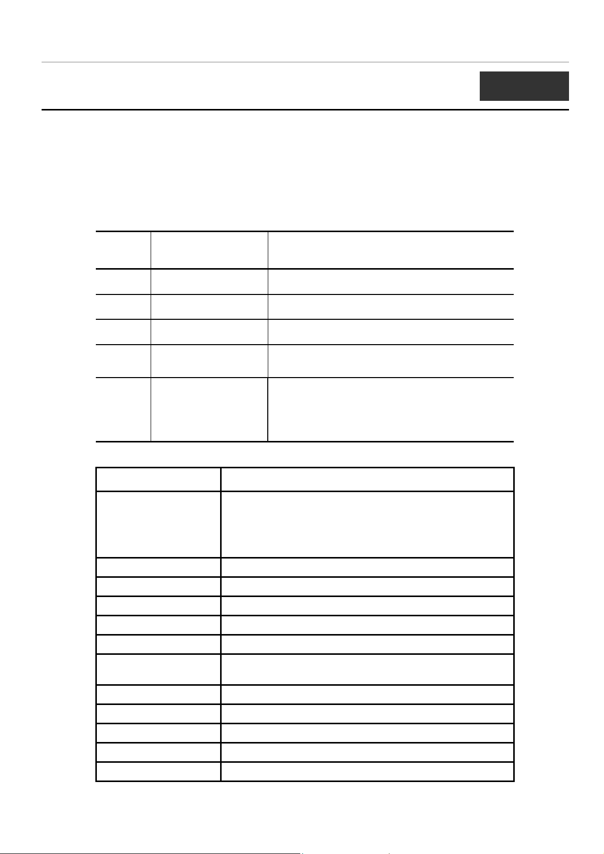
The DGS-3024 supports the Simple Network Management Protocol (SNMP) versions 1, 2c, and 3. The user may specify which
version of the SNMP to use to monitor and control the Switch. The three versions of SNMP vary in the level of security
provided between the management station and the network device. The following table lists the security features of the three
SNMP versions:
SNMP
Version
v1 Community String
v2c Community String
v3 Username
v3 MD5 or SHA
v3 MD5 DES or SHA DES
Authentication Method Description
Community String is used for authentication − NoAuthNoPriv
Community String is used for authentication − NoAuthNoPriv
Username is used for authentication − NoAuthNoPriv
Authentication is based on the HMAC-MD5 or HMAC-SHA algorithms
− AuthNoPriv
Authentication is based on the HMAC-MD5 or HMAC-SHA algorithms
− AuthPriv.
DES 32-bit encryption is added based on the CBC-DES (DES-32)
standard
Command Parameters
create snmp user <username 32> <groupname 32> {encrypted [by_password
auth [md5 <auth_password 8-16> | sha <auth_password 820>] priv [none | des <priv_password 8-16>] | by_key auth
[md5 <auth_key 32-32>| sha<auth_key 40-40>] priv [none |
des <priv_key 32-32>]]}
delete snmp user <username 32>
show snmp user
create snmp view <view_name 32> <oid> view_type [included | excluded]
delete snmp view <view_name 32> [all | oid]
show snmp view {<view_name 32>}
create snmp community <community_string 32> view <view_name 32> [read_only |
read_write]
delete snmp community <community_string 32>
show snmp community {<community_string 32>}
config snmp engineID <snmp_engineID>
show snmp engineID
create snmp group <groupname 32> [v1 | v2c | v3 [noauth_nopriv | auth_nopriv |
25
Page 28
DGS-3024 Layer 2 Switch CLI Reference Manual
Command Parameters
auth_priv]] {read_view <view_name 32> | write_view
<view_name 32> | notify_view <view_name 32>}
delete snmp group <groupname 32>
show snmp groups
create snmp host <ipaddr> [v1 | v2c | v3 [noauth_nopriv | auth_nopriv |
auth_priv]] <auth_string 32>
delete snmp host <ipaddr>
show snmp host {<ipaddr>}
enable rmon
disable rmon
create trusted_host <ipaddr>
delete trusted_host <ipaddr>
show trusted_host <ipaddr>
enable snmp traps
disable snmp traps
enable snmp
authenticate traps
disable snmp
authenticate traps
show snmp traps
config snmp
system_contact
config snmp
system_location
config snmp
system_name
Each command is listed, in detail, in the following sections.
<sw_contact>
<sw_location>
<sw_name>
create snmp user
Purpose Used to create a new SNMP user and adds the user to an SNMP
group that is also created by this command.
Syntax
create snmp user <username 32> <groupname 32> {encrypted
[by_password auth [md5 <auth_password 8-16> | sha
<auth_password 8-20>] priv [none | des <priv_password 8-16>] |
by_key auth [md5 <auth_key 32-32>| sha <auth_key 40-40>] priv
[none | des <priv_key 32-32>]]}
Description
Parameters
The create snmp user command creates a new SNMP user and
adds the user to an SNMP group that is also created by this
command.
<username 32> − An alphanumeric name of up to 32 characters that
will identify the new SNMP user.
<groupname 32> − An alphanumeric name of up to 32 characters
26
Page 29

DGS-3024 Layer 2 Switch CLI Reference Manual
create snmp user
that will identify the SNMP group the new SNMP user will be
associated with.
encrypted – Allows the user to choose a type of authorization for
authentication using SNMP. The user may choose:
auth - The user may also choose the type of authentication
algorithms used to authenticate the snmp user. The choices are:
•
by_password – Requires the SNMP user to enter a
password for authentication and privacy. The password is
defined by specifying the auth_password below. This
method is recommended.
•
by_key – Requires the SNMP user to enter a encryption
key for authentication and privacy. The key is defined by
specifying the key in hex form below. This method is not
recommended.
•
md5 − Specifies that the HMAC-MD5-96 authentication
level will be used. md5 may be utilized by entering one of
the following:
<auth password 8-16> - An alphanumeric sting of
between 8 and 16 characters that will be used to
authorize the agent to receive packets for the host.
<auth_key 32-32> - Enter an alphanumeric sting of
exactly 32 characters, in hex form, to define the key that
will be used to authorize the agent to receive packets for
the host.
•
sha − Specifies that the HMAC-SHA-96 authentication level
will be used.
<auth password 8-20> - An alphanumeric sting of
between 8 and 20 characters that will be used to
authorize the agent to receive packets for the host.
<auth_key 40-40> - An alphanumeric sting of exactly
40 characters, in hex form, to define the key that will be
used to authorize the agent to receive packets for the
host.
priv – Adding the priv (privacy) parameter will allow for encryption in
addition to the authentication algorithm for higher security. The user
may choose:
•
des – Adding this parameter will allow for a 56-bit
encryption to be added using the DES-56 standard using:
<priv_password 8-16> - An alphanumeric string of
between 8 and 16 characters that will be used to
encrypt the contents of messages the host sends to
the agent.
<priv_key 32-32> - An alphanumeric key string of
exactly 32 characters, in hex form, that will be used to
encrypt the contents of messages the host sends to
27
Page 30
create snmp user
Restrictions Only administrator-level users can issue this command.
Example usage:
To create an SNMP user on the Switch:
DGS-3024 Layer 2 Switch CLI Reference Manual
the agent.
none – Adding this parameter will add no encryption.
DGS-3024:4#create snmp user dlink default encrypted
by_password auth md5 auth_password priv none
Command: create snmp user dlink default encrypted
by_password auth md5 auth_password priv none
Success.
DGS-3024:4#
Example usage:
To delete a previously entered SNMP user on the Switch:
delete snmp user
Purpose Used to remove an SNMP user from an SNMP group and also to
delete the associated SNMP group.
Syntax
Description
Parameters
Restrictions Only administrator-level users can issue this command.
DGS-3024:4#delete snmp user dlink
Command: delete snmp user dlink
Success.
DGS-3024:4#
delete snmp user <username 32>
The delete snmp user command removes an SNMP user from its
SNMP group and then deletes the associated SNMP group.
<username 32> − An alphanumeric string of up to 32 characters that
identifies the SNMP user that will be deleted.
28
Page 31

DGS-3024 Layer 2 Switch CLI Reference Manual
show snmp user
Purpose Used to display information about each SNMP username in the
SNMP group username table.
Example usage:
To display the SNMP users currently configured on the Switch:
Syntax
Description The show snmp user command displays information about each
Parameters None.
Restrictions Only administrator-level users can issue this command.
DGS-3024:4#show snmp user
Command: show snmp user
Username Group Name SNMP Version Auth-Protocol PrivProtocol
--------------- --------------- ------------ ------------- ----------- initial initial V3 None None
Total Entries: 1
DGS-3024:4#
show snmp user
SNMP username in the SNMP group username table.
Example usage:
create snmp view
Purpose Used to assign views to community strings to limit which MIB objects
and SNMP manager can access.
Syntax
Description The create snmp view command assigns views to community strings
Parameters
Restrictions Only administrator-level users can issue this command.
create snmp view <view_name 32> <oid> view_type [included |
excluded]
to limit which MIB objects an SNMP manager can access.
<view_name 32> − An alphanumeric string of up to 32 characters
that identifies the SNMP view that will be created.
<oid> − The object ID that identifies an object tree (MIB tree) that will
be included or excluded from access by an SNMP manager.
included − Include this object in the list of objects that an SNMP
manager can access.
excluded − Exclude this object from the list of objects that an SNMP
manager can access.
To create an SNMP view:
29
Page 32

DGS-3024 Layer 2 Switch CLI Reference Manual
DGS-3024:4#create snmp view dlinkview 1.3.6 view_type included
Command: create snmp view dlinkview 1.3.6 view_type included
Success.
DGS-3024:4#
delete snmp view
Purpose Used to remove an SNMP view entry previously created on the
Switch.
Example usage:
To delete a previously configured SNMP view from the Switch:
Syntax
Description
Parameters
Restrictions Only administrator-level users can issue this command.
DGS-3024:4#delete snmp view dlinkview all
Command: delete snmp view dlinkview all
Success.
delete snmp view <view_name 32> [all | <oid>]
The delete snmp view command is used to remove an SNMP view
previously created on the Switch.
<view_name 32> − An alphanumeric string of up to 32 characters
that identifies the SNMP view to be deleted.
all − Specifies that all of the SNMP views on the Switch will be
deleted.
<oid> − The object ID that identifies an object tree (MIB tree) that will
be deleted from the Switch.
Example usage:
To display SNMP view configuration:
DGS-3024:4#
show snmp view
Purpose Used to display an SNMP view previously created on the Switch.
Syntax
Description
Parameters
Restrictions None.
show snmp view {<view_name 32>}
The show snmp view command displays an SNMP view previously
created on the Switch.
<view_name 32> − An alphanumeric string of up to 32 characters
that identifies the SNMP view that will be displayed.
30
Page 33

DGS-3024 Layer 2 Switch CLI Reference Manual
DGS-3024:4#show snmp view
Command: show snmp view
Vacm View Table Settings
View Name Subtree View Type
-------------------- ------------------------- --------- ReadView 1 Included
WriteView 1 Included
NotifyView 1.3.6 Included
restricted 1.3.6.1.2.1.1 Included
restricted 1.3.6.1.2.1.11 Included
restricted 1.3.6.1.6.3.10.2.1 Included
restricted 1.3.6.1.6.3.11.2.1 Included
restricted 1.3.6.1.6.3.15.1.1 Included
CommunityView 1 Included
CommunityView 1.3.6.1.6.3 Excluded
CommunityView 1.3.6.1.6.3.1 Included
Total Entries: 11
DGS-3024:4#
create snmp community
Purpose Used to create an SNMP community string to define the relationship
between the SNMP manager and an agent. The community string
acts like a password to permit access to the agent on the Switch.
One or more of the following characteristics can be associated with
the community string:
An Access List of IP addresses of SNMP managers that are permitted
to use the community string to gain access to the Switch’s SNMP
agent.
An MIB view that defines the subset of all MIB objects that will be
accessible to the SNMP community.
Read/write or read-only level permission for the MIB objects
accessible to the SNMP community.
Syntax
Description
create snmp community <community_string 32> view
<view_name 32> [read_only | read_write]
The create snmp community command is used to create an SNMP
community string and to assign access-limiting characteristics to this
community string.
Parameters
<community_string 32> − An alphanumeric string of up to 32
characters that is used to identify members of an SNMP community.
This string is used like a password to give remote SNMP managers
access to MIB objects in the Switch’s SNMP agent.
<view_name 32> − An alphanumeric string of up to 32 characters that
is used to identify the group of MIB objects that a remote SNMP
manager is allowed to access on the Switch.
read_only − Specifies that SNMP community members using the
community string created with this command can only read the
contents of the MIBs on the Switch.
31
Page 34

create snmp community
Restrictions Only administrator-level users can issue this command.
Example usage:
To create the SNMP community string “dlink:”
DGS-3024 Layer 2 Switch CLI Reference Manual
read_write − Specifies that SNMP community members using the
community string created with this command can read from and write
to the contents of the MIBs on the Switch.
DGS-3024:4#create snmp community dlink view ReadView read_write
Command: create snmp community dlink view ReadView read_write
Success.
DGS-3024:4#
Example usage:
To delete the SNMP community string “dlink:”
delete snmp community
Purpose Used to remove a specific SNMP community string from the Switch.
Syntax
Description
Parameters
Restrictions Only administrator-level users can issue this command.
DGS-3024:4#delete snmp community dlink
Command: delete snmp community dlink
Success.
delete snmp community <community_string 32>
The delete snmp community command is used to remove a
previously defined SNMP community string from the Switch.
<community_string 32> − An alphanumeric string of up to 32
characters that is used to identify members of an SNMP community
to delete. This string is used like a password to give remote SNMP
managers access to MIB objects in the Switch’s SNMP agent.
DGS-3024:4#
32
Page 35

DGS-3024 Layer 2 Switch CLI Reference Manual
show snmp community
Purpose Used to display SNMP community strings configured on the Switch.
Example usage:
To display the currently entered SNMP community strings:
Syntax
Description
Parameters
Restrictions None.
DGS-3024:4#show snmp community
Command: show snmp community
SNMP Community Table
Community Name View Name Access Right
-------------------------------- -------------------------- -----------dlink ReadView read_write
private CommunityView read_write
public CommunityView read_only
show snmp community {<community_string 32>}
The show snmp community command is used to display SNMP
community strings that are configured on the Switch.
<community_string 32> − An alphanumeric string of up to 32
characters that is used to identify members of an SNMP
community. This string is used like a password to give remote
SNMP managers access to MIB objects in the Switch’s SNMP
agent.
Example usage:
To give the SNMP agent on the Switch the name “0035636666”
Total Entries: 3
DGS-3024:4#
config snmp engineID
Purpose Used to configure a name for the SNMP engine on the Switch.
Syntax
Description
Parameters
Restrictions Only administrator-level users can issue this command.
config snmp engineID <snmp_engineID>
The config snmp engineID command configures a name for the
SNMP engine on the Switch.
<snmp_engineID> − An alphanumeric string that will be used to
identify the SNMP engine on the Switch.
33
Page 36

DGS-3024 Layer 2 Switch CLI Reference Manual
DGS-3024:4#config snmp engineID 0035636666
Command: config snmp engineID 0035636666
Success.
DGS-3024:4#
show snmp engineID
Purpose Used to display the identification of the SNMP engine on the Switch.
Example usage:
To display the current name of the SNMP engine on the Switch:
Syntax
Description
Parameters None.
Restrictions None.
DGS-3024:4#show snmp engineID
Command: show snmp engineID
SNMP Engine ID : 0035636666
DGS-3024:4#
show snmp engineID
The show snmp engineID command displays the identification of
the SNMP engine on the Switch.
create snmp group
Purpose Used to create a new SNMP group, or a table that maps SNMP
users to SNMP views.
Syntax
Description
Parameters
create snmp group <groupname 32> [v1 | v2c | v3
[noauth_nopriv | auth_nopriv | auth_priv]] {read_view
<view_name 32> | write_view <view_name 32> | notify_view
<view_name 32>}
The create snmp group command creates a new SNMP group, or a
table that maps SNMP users to SNMP views.
<groupname 32> − An alphanumeric name of up to 32 characters
that will identify the SNMP group the new SNMP user will be
associated with.
v1 – Specifies that SNMP version 1 will be used. The Simple
Network Management Protocol (SNMP), version 1, is a network
management protocol that provides a means to monitor and control
network devices.
v2c – Specifies that SNMP version 2c will be used. The SNMP v2c
supports both centralized and distributed network management
34
Page 37

DGS-3024 Layer 2 Switch CLI Reference Manual
create snmp group
strategies. It includes improvements in the Structure of Management
Information (SMI) and adds some security features.
v3 – Specifies that the SNMP version 3 will be used. SNMP v3
provides secure access to devices through a combination of
authentication and encrypting packets over the network. SNMP v3
adds:
tampered with during transit.
valid source.
prevent it being viewed by an unauthorized source.
noauth_nopriv − Specifies that there will be no authorization and no
encryption of packets sent between the Switch and a remote SNMP
manager.
auth_nopriv − Specifies that authorization will be required, but there
will be no encryption of packets sent between the Switch and a
remote SNMP manager.
Message integrity − Ensures that packets have not been
Authentication − Determines if an SNMP message is from a
Encryption − Scrambles the contents of messages to
auth_priv − Specifies that authorization will be required, and that
packets sent between the Switch and a remote SNMP manger will
be encrypted.
read_view – Specifies that the SNMP group being created can
request SNMP messages.
<view_name 32> − An alphanumeric string of up to 32
characters that is used to identify the group of MIB objects that
a remote SNMP manager is allowed to access on the Switch.
write_view – Specifies that the SNMP group being created has write
privileges.
<view_name 32> − An alphanumeric string of up to 32
characters that is used to identify the group of MIB objects that
a remote SNMP manager is allowed to access on the Switch.
notify_view − Specifies that the SNMP group being created can
receive SNMP trap messages generated by the Switch’s SNMP
agent.
<view_name 32> − An alphanumeric string of up to 32
characters that is used to identify the group of MIB objects that
a remote SNMP manager is allowed to access on the Switch.
Example usage:
To create an SNMP group named “sg1:”
Restrictions Only administrator-level users can issue this command.
35
Page 38

DGS-3024 Layer 2 Switch CLI Reference Manual
DGS-3024:4#create snmp group sg1 v3 noauth_nopriv read_view
v1 write_view v1 notify_view v1
Command: create snmp group sg1 v3 noauth_nopriv read_view v1
write_view v1 notify_view v1
Success.
DGS-3024:4#
delete snmp group
Purpose Used to remove an SNMP group from the Switch.
Example usage:
To delete the SNMP group named “sg1”.
Syntax
Description
Parameters
Restrictions Only administrator-level users can issue this command.
DGS-3024:4#delete snmp group sg1
Command: delete snmp group sg1
Success.
DGS-3024:4#
delete snmp group <groupname 32>
The delete snmp group command is used to remove an SNMP
group from the Switch.
<groupname 32> − An alphanumeric name of up to 32 characters
that will identify the SNMP group the new SNMP user will be
associated with.
Example usage:
To display the currently configured SNMP groups on the Switch:
show snmp groups
Purpose Used to display the group-names of SNMP groups currently
configured on the Switch. The security model, level, and status of
each group are also displayed.
Syntax
Description
Parameters None.
Restrictions None.
show snmp groups
The show snmp groups command displays the group-names of
SNMP groups currently configured on the Switch. The security
model, level, and status of each group are also displayed.
36
Page 39

DGS-3024 Layer 2 Switch CLI Reference Manual
DGS-3024:4#show snmp groups
Command: show snmp groups
Vacm Access Table Settings
Group Name : Group3
ReadView Name : ReadView
WriteView Name : WriteView
Notify View Name : NotifyView
Security Model : SNMPv3
Security Level : NoAuthNoPriv
Group Name : Group4
ReadView Name : ReadView
WriteView Name : WriteView
Notify View Name : NotifyView
Security Model : SNMPv3
Security Level : authNoPriv
Group Name : Group5
ReadView Name : ReadView
WriteView Name : WriteView
Notify View Name : NotifyView
Security Model : SNMPv3
Security Level : authNoPriv
Group Name : Group6
ReadView Name : ReadView
WriteView Name : WriteView
Notify View Name : NotifyView
Security Model : SNMPv3
Security Level : authPriv
Group Name : Group7
ReadView Name : ReadView
WriteView Name : WriteView
Notify View Name : NotifyView
Security Model : SNMPv3
Security Level : authPriv
Group Name : initial
ReadView Name : restricted
WriteView Name :
Notify View Name : restricted
Security Model : SNMPv3
Security Level : NoAuthNoPriv
Group Name : ReadGroup
ReadView Name : CommunityView
WriteView Name :
Notify View Name : CommunityView
Security Model : SNMPv1
Security Level : NoAuthNoPriv
Group Name : ReadGroup
37
Page 40

DGS-3024 Layer 2 Switch CLI Reference Manual
ReadView Name : CommunityView
WriteView Name :
Notify View Name : CommunityView
Security Model : SNMPv2
Security Level : NoAuthNoPriv
Group Name : WriteGroup
ReadView Name : CommunityView
WriteView Name : CommunityView
Notify View Name : CommunityView
Security Model : SNMPv1
Security Level : NoAuthNoPriv
Group Name : WriteGroup
ReadView Name : CommunityView
WriteView Name : CommunityView
Notify View Name : CommunityView
Security Model : SNMPv2
Security Level : NoAuthNoPriv
Total Entries: 10
DGS-3024:4#
create snmp host
Purpose Used to create a recipient of SNMP traps generated by the Switch’s
SNMP agent.
Syntax
Description
Parameters
create snmp host <ipaddr> [v1 | v2c | v3 [noauth_nopriv |
auth_nopriv | auth_priv] <auth_string 32>]
The create snmp host command creates a recipient of SNMP traps
generated by the Switch’s SNMP agent.
<ipaddr> − The IP address of the remote management station that
will serve as the SNMP host for the Switch.
v1 – Specifies that SNMP version 1 will be used. The Simple
Network Management Protocol (SNMP), version 1, is a network
management protocol that provides a means to monitor and control
network devices.
v2c – Specifies that SNMP version 2c will be used. The SNMP v2c
supports both centralized and distributed network management
strategies. It includes improvements in the Structure of Management
Information (SMI) and adds some security features.
v3 – Specifies that the SNMP version 3 will be used. SNMP v3
provides secure access to devices through a combination of
authentication and encrypting packets over the network. SNMP v3
adds:
Message integrity − ensures that packets have not been
tampered with during transit.
Authentication − determines if an SNMP message is from a
valid source.
38
Page 41

DGS-3024 Layer 2 Switch CLI Reference Manual
create snmp host
noauth_nopriv − Specifies that there will be no authorization and no
encryption of packets sent between the Switch and a remote SNMP
manager.
auth_nopriv − Specifies that authorization will be required, but there
will be no encryption of packets sent between the Switch and a
remote SNMP manager.
auth_priv − Specifies that authorization will be required, and that
packets sent between the Switch and a remote SNMP manger will
be encrypted.
Encryption − scrambles the contents of messages to prevent
it being viewed by an unauthorized source.
Example usage:
To create an SNMP host to receive SNMP messages:
<auth_sting 32>
remote SNMP manager to access the Switch’s SNMP agent.
Restrictions Only administrator-level users can issue this command.
DGS-3024:4#create snmp host 10.48.74.100 v3 auth_priv public
Command: create snmp host 10.48.74.100 v3 auth_priv public
Success.
DGS-3024:4#
−
An alphanumeric string used to authorize a
delete snmp host
Purpose Used to remove a recipient of SNMP traps generated by the Switch’s
SNMP agent.
Syntax
delete snmp host <ipaddr>
Example usage:
To delete an SNMP host entry:
Description
Parameters
Restrictions Only administrator-level users can issue this command.
The delete snmp host command deletes a recipient of SNMP traps
generated by the Switch’s SNMP agent.
<ipaddr> − The IP address of a remote SNMP manager that will
receive SNMP traps generated by the Switch’s SNMP agent.
39
Page 42

DGS-3024 Layer 2 Switch CLI Reference Manual
DGS-3024:4#delete snmp host 10.48.74.100
Command: delete snmp host 10.48.74.100
Success.
DGS-3024:4#
show snmp host
Purpose Used to display the recipient of SNMP traps generated by the
Switch’s SNMP agent.
Example usage:
To display the currently configured SNMP hosts on the Switch:
DGS-3024:4#show snmp host
Command: show snmp host
SNMP Host Table
Host IP Address SNMP Version Community Name / SNMPv3 User Name
--------------- --------------------- ------------------------------
10.48.76.23 V2c private
10.48.74.100 V3 public
Total Entries: 2
Syntax
Description
Parameters
Restrictions None.
show snmp host {<ipaddr>}
The show snmp host command is used to display the IP addresses
and configuration information of remote SNMP managers that are
designated as recipients of SNMP traps that are generated by the
Switch’s SNMP agent.
<ipaddr> − The IP address of a remote SNMP manager that will
receive SNMP traps generated by the Switch’s SNMP agent.
DGS-3024:4#
Example Usage:
enable rmon
Purpose Used to enable RMON on the Switch.
Syntax
Description
Parameters None.
Restrictions Only administrator-level users can issue this command.
enable rmon
This command is used, in conjunction with the disable rmon
command below, to enable and disable remote monitoring (RMON)
on the Switch.
40
Page 43

To enable RMON:
DGS-3024:4#enable rmon
Command: enable rmon
Success.
DGS-3024:4#
disable rmon
Purpose Used to disable RMON on the Switch.
DGS-3024 Layer 2 Switch CLI Reference Manual
Syntax
Description
Parameters None.
Restrictions Only administrator-level users can issue this command.
Example Usage:
To disable RMON:
DGS-3024:4#disable rmon
Command: disable rmon
Success.
DGS-3024:4#
create trusted_host
disable rmon
This command is used, in conjunction with the enable rmon
command above, to enable and disable remote monitoring (RMON)
on the Switch.
Purpose Used to create the trusted host.
Syntax
Description
Parameters
Restrictions Only administrator-level users can issue this command.
Example usage:
To create the trusted host:
create trusted_host <ipaddr>
The create trusted_host command creates the trusted host. The
Switch allows you to specify up to four IP addresses that are allowed
to manage the Switch via in-band SNMP or TELNET based
management software. These IP addresses must be members of the
Management VLAN. If no IP addresses are specified, then there is
nothing to prevent any IP address from accessing the Switch,
provided the user knows the Username and Password.
<ipaddr> − The IP address of the trusted host to be created.
41
Page 44

DGS-3024 Layer 2 Switch CLI Reference Manual
DGS-3024:4#create trusted_host 10.48.74.121
Command: create trusted_host 10.48.74.121
Success.
DGS-3024:4#
show trusted_host
Purpose Used to display a list of trusted hosts entered on the Switch using
the create trusted_host command above.
Example Usage:
To display the list of trust hosts:
Syntax
Description This command is used to display a list of trusted hosts entered on
Parameters
Restrictions None.
DGS-3024:4#show trusted_host
Command: show trusted_host
Management Stations
IP Address
-----------------------
10.53.13.94
Total Entries: 1
DGS-3024:4#
show trusted_host {<ipaddr>}
the Switch using the create trusted_host command above.
<ipaddr> − The IP address of the trusted host.
delete trusted_host
Purpose
Syntax
Description This command is used to delete a trusted host entry made using the
Parameters
Restrictions Only administrator-level users can issue this command.
Example Usage:
To delete a trusted host with an IP address 10.48.74.121:
Used to delete a trusted host entry made using the create
trusted_host command above.
delete trusted _host <ipaddr>
create trusted_host command above.
<ipaddr> − The IP address of the trusted host.
42
Page 45

DGS-3024 Layer 2 Switch CLI Reference Manual
DGS-3024:4#delete trusted_host 10.48.74.121
Command: delete trusted_host 10.48.74.121
Success.
DGS-3024:4#
enable snmp traps
Purpose Used to enable SNMP trap support.
Syntax
Description
Parameters None.
Restrictions Only administrator-level users can issue this command.
Example usage:
To enable SNMP trap support on the Switch:
DGS-3024:4#enable snmp traps
Command: enable snmp traps
Success.
DGS-3024:4#
enable snmp traps
The enable snmp traps command is used to enable SNMP trap
support on the Switch.
disable snmp traps
Purpose Used to disable SNMP trap support on the Switch.
Syntax
disable snmp traps
Description This command is used to disable SNMP trap support on the
Parameters None.
Restrictions Only administrator-level users can issue this command.
Example Usage:
To prevent SNMP traps from being sent from the Switch:
Switch.
DGS-3024:4#disable snmp traps
Command: disable snmp traps
Success.
DGS-3024:4#
43
Page 46

DGS-3024 Layer 2 Switch CLI Reference Manual
enable snmp authenticate trap
Purpose Used to enable SNMP authentication trap support.
Syntax
Description This command is used to enable SNMP authentication trap
Parameters None.
Restrictions Only administrator-level users can issue this command.
Example Usage:
To turn on SNMP authentication trap support:
disable snmp authenticate trap
Purpose Used to disable SNMP authentication trap support.
enable snmp authenticate trap
support on the Switch.
DGS-3024:4#enable snmp authenticate trap
Command: enable snmp authenticate trap
Success.
DGS-3024:4#
Syntax
Description This command is used to disable SNMP authentication support on
Parameters None.
Restrictions Only administrator-level users can issue this command.
Example Usage:
To disable the SNMP authentication trap support:
show snmp traps
Purpose Used to show SNMP trap support on the Switch .
disable snmp authenticate trap
the Switch.
DGS-3024:4#disable snmp authenticate trap
Command: disable snmp authenticate trap
Success.
DGS-3024:4#
Syntax
Description This command is used to view the SNMP trap support status
show snmp traps
currently configured on the Switch.
44
Page 47

DGS-3024 Layer 2 Switch CLI Reference Manual
show snmp traps
Parameters None.
Restrictions Only administrator-level users can issue this command.
Example usage:
To view the current SNMP trap support:
DGS-3024:4#show snmp traps
Command: show snmp traps
SNMP Traps : Enabled
Authenticate Trap : Enabled
DGS-3024:4#
config snmp system_contact
Purpose Used to enter the name of a contact person who is responsible for
the Switch.
Syntax
Description
Parameters <sw_contact> - A maximum of 255 characters is allowed. A NULL
Restrictions Only administrator-level users can issue this command.
Example usage:
To configure the Switch contact to “
DGS-3024:4#config snmp system_contact MIS Department II
Command: config snmp system_contact MIS Department II
Success.
DGS-3024:4#
config snmp system_contact {<sw_contact>}
The config snmp system_contact command is used to enter the
name and/or other information to identify a contact person who is
responsible for the Switch. A maximum of 255 character can be
used.
string is accepted if there is no contact.
MIS Department II
”:
45
Page 48

DGS-3024 Layer 2 Switch CLI Reference Manual
config snmp system_location
Purpose Used to enter a description of the location of the Switch.
Syntax
Description
Parameters <sw_location> - A maximum of 255 characters is allowed. A NULL
Restrictions Only administrator-level users can issue this command.
Example usage:
To configure the Switch location for “
DGS-3024:4#config snmp system_location HQ 5F
Command: config snmp system_location HQ 5F
Success.
DGS-3024:4#
config snmp system_location {<sw_location>}
The config snmp system_location command is used to enter a
description of the location of the Switch. A maximum of 255
characters can be used.
string is accepted if there is no location desired.
HQ 5F
”:
config snmp system_name
Purpose Used to configure the name for the Switch.
Syntax
Description
Parameters <sw_name> - A maximum of 255 characters is allowed. A NULL
Restrictions Only administrator-level users can issue this command.
Example usage:
To configure the Switch name for “
DGS-3024:4#config snmp system_name DGS-3024 Switch
Command: config snmp system_name DGS-3024 Switch
Success.
DGS-3024:4#
config snmp system_name {<sw_name>}
The config snmp system_name command configures the name
of the Switch.
string is accepted if no name is desired.
DGS-3024 Switch”
:
46
Page 49

DGS-3024 Layer 2 Switch CLI Reference Manual
7
MAC NOTIFICATION COMMANDS
The MAC notification commands in the Command Line Interface (CLI) are listed, in the following table, along with their
appropriate parameters.
Command Parameters
enable mac_notification
disable mac_notification
config mac_notification {interval <int 1-2147483647> | historysize <int 1-500>}
config mac_notification ports [<portlist> | all] [enable | disable]
show mac_notification
show mac_notification ports <portlist>
Each command is listed, in detail, in the following sections.
Example Usage:
To enable MAC notification without changing basic configuration:
enable mac_notification
Purpose Used to enable global MAC address table notification on the
Switch.
Syntax
Description This command is used to enable MAC Address Notification without
Parameters None.
Restrictions Only administrator-level users can issue this command.
DGS-3024:4#enable mac_notification
Command: enable mac_notification
Success.
DGS-3024:4#
enable mac_notification
changing configuration.
disable mac_notification
Purpose Used to disable global MAC address table notification on the Switch.
Syntax
Description This command is used to disable MAC Address Notification without
Parameters None.
Restrictions Only administrator-level users can issue this command.
disable mac_notification
changing configuration.
47
Page 50

Example Usage:
To disable MAC notification without changing basic configuration:
config mac_notification
Purpose Used to configure MAC address notification.
DGS-3024 Layer 2 Switch CLI Reference Manual
DGS-3024:4#disable mac_notification
Command: disable mac_notification
Success.
DGS-3024:4#
Syntax
Description MAC address notification is used to monitor MAC addresses
Parameters interval <int 1-2147483647> - The time in seconds between
Restrictions Only administrator-level users can issue this command.
Example usage:
To configure the Switch’s MAC address table notification global settings:
DGS-3024:4#config mac_notification interval 1 historysize 500
Command: config mac_notification interval 1 historysize 500
Success.
DGS-3024:4#
config mac_notification {interval <int 1-2147483647> |
historysize <int 1-500>
learned and entered into the FDB.
notifications. The user may choose an interval between 1 and
2,147,483,647 seconds.
historysize <1-500> - The maximum number of entries listed in the
history log used for notification.
config mac_notification ports
Purpose Used to configure MAC address notification status settings.
Syntax
Description MAC address notification is used to monitor MAC addresses learned
Parameters <portlist> - Specify a port or range of ports to be configured.
config mac_notification ports [<portlist> | all] [enable | disable]
and entered into the FDB.
all – Entering this command will allow the configuration of all ports on
the system.
[enable | disable] – These commands will enable or disable MAC
48
Page 51

config mac_notification ports
Restrictions Only administrator-level users can issue this command.
Example usage:
To enable port 7 for MAC address table notification:
DGS-3024 Layer 2 Switch CLI Reference Manual
address table notification on the Switch.
DGS-3024:4#config mac_notification ports 7 enable
Command: config mac_notification ports 7 enable
Success.
DGS-3024:4#
show mac_notification
Purpose Used to display the Switch’s MAC address table notification global
settings.
Syntax
Description This command is used to display the Switch’s MAC address table
Parameters None.
Restrictions Only administrator-level users can issue this command.
Example usage:
To view the Switch’s MAC address table notification global settings:
DGS-3024:4#show mac_notification
Command: show mac_notification
Global Mac Notification Settings
State : Enabled
Interval : 1
History Size : 1
show mac_notification
notification global settings.
DGS-3024:4#
49
Page 52

DGS-3024 Layer 2 Switch CLI Reference Manual
show mac_notification ports
Purpose Used to display the Switch’s MAC address table notification status
settings.
Syntax
Description This command is used to display the Switch’s MAC address table
Parameters <portlist> - Specify a port or group of ports to be viewed.
Restrictions None
Example usage:
To display all port’s MAC address table notification status settings:
DGS-3024:4#show mac_notification ports
Command: show mac_notification ports
Port # MAC Address Table Notification State
------ -----------------------------------1 Disabled
2 Disabled
3 Disabled
4 Disabled
5 Disabled
6 Disabled
7 Disabled
8 Disabled
9 Disabled
10 Disabled
11 Disabled
12 Disabled
13 Disabled
14 Disabled
15 Disabled
16 Disabled
17 Disabled
18 Disabled
19 Disabled
20 Disabled
CTRL+C ESC q Quit SPACE n Next Page p Previous Page r Refresh
show mac_notification ports <portlist>
notification status settings.
Entering this command without the parameter will display the MAC
notification table for all ports.
50
Page 53

DGS-3024 Layer 2 Switch CLI Reference Manual
8
DOWNLOAD/UPLOAD COMMANDS
The download/upload commands in the Command Line Interface (CLI) are listed (along with the appropriate parameters) in the
following table.
Command Parameters
download [firmware <ipaddr> <path_filename 64> | configuration <ipaddr>
<path_filename 64> {increment}]
upload [configuration | log] <ipaddr> <path_filename 64>
Each command is listed, in detail, in the following sections.
download
Purpose Used to download and install new firmware or a switch configuration
file from a TFTP server.
Syntax
Description This command is used to download a new firmware or a switch
Parameters
Restrictions The TFTP server must be on the same IP subnet as the Switch.
Example usage:
To download a firmware file:
download [firmware <ipaddr> <path_filename 64> |
configuration <ipaddr> <path_filename 64> {increment}]
configuration file from a TFTP server.
firmware − Download and install new firmware on the Switch from a
TFTP server.
configuration − Download a switch configuration file from a TFTP
server.
<ipaddr> − The IP address of the TFTP server.
<path_filename> − The DOS path and filename of the firmware or
switch configuration file on the TFTP server. For example,
C:\3024.had.
increment − Allows the download of a partial switch configuration file.
This allows a file to be downloaded that will change only the Switch
parameters explicitly stated in the configuration file. All other switch
parameters will remain unchanged.
Only administrator-level users can issue this command.
DGS-3024:4#download firmware 10.48.74.121 c:\dgs-3024 b08.had
Command: download firmware 10.48.74.121 c:\dgs-3024 b08.had
Connecting to server................... Done.
Download firmware...........……… Done. Do not power off!
Please wait, programming flash…….. Done.
Saving current settings to NV-RAM……Done.
Please wait, the switch is rebooting….
51
Page 54

DGS-3024 Layer 2 Switch CLI Reference Manual
Example usage:
To download a configuration file:
DGS-3024:4#download configuration 10.48.74.121 c:\cfg\setting.txt
Command: download configuration 10.48.74.121 c:\cfg\setting.txt
Connecting to server................... Done.
Download configuration............. Done.
DGS-3024:4#
upload
Purpose Used to upload the current switch settings or the Switch history log
to a TFTP server.
Syntax
Description This command is used to upload either the Switch’s current settings
Parameters
Restrictions The TFTP server must be on the same IP subnet as the Switch.
Example usage:
To upload a log file:
DGS-3024:4#upload log 10.48.74.121 c:\cfg\log.txt
Command: upload log 10.48.74.121 c:\cfg\log.txt
Connecting to server................... Done.
Upload configuration...................Done.
DGS-3024:4#
upload [configuration | log] <ipaddr> <path_filename 64>
or the Switch’s history log to a TFTP server.
configuration − Specifies that the Switch’s current settings will be
uploaded to the TFTP server.
log − Specifies that the Switch history log will be uploaded to the
TFTP server.
<ipaddr> − The IP address of the TFTP server. The TFTP server
must be on the same IP subnet as the Switch.
<path_filename 64> − Specifies the location of the Switch
configuration file on the TFTP server. This file will be replaced by the
uploaded file from the Switch.
Only administrator-level users can issue this command.
52
Page 55

DGS-3024 Layer 2 Switch CLI Reference Manual
Example usage:
To upload a configuration file:
DGS-3024:4#upload configuration 10.48.74.121 c:\cfg\setting.txt
Command: upload configuration 10.48.74.121 c:\cfg\setting.txt
Connecting to server................... Done.
Upload configuration...................Done.
DGS-3024:4#
53
Page 56

DGS-3024 Layer 2 Switch CLI Reference Manual
9
NETWORK MONITORING COMMANDS
The network monitoring commands in the Command Line Interface (CLI) are listed (along with the appropriate parameters) in
the following table.
Command Parameters
show packet ports <portlist>
show error ports <portlist>
show utilization
clear counters
clear log
show log {index <value>}
enable syslog
disable syslog
show syslog
create syslog host <index 1-4> ipaddress <ipaddr> {severity [informational | warning |
all | facility [local0 | local1| local2 | local3 | local4 | local5 | local6 |
local7] | udp_port <udp_port_number> state [enable | disable]
config syslog {host [all <index 1-4>]} {severity [informational | warning | all] |
facility [local0 | local1 | local2 | local3 | local4 | local5 | local6 |
local7] | udp_port <udp_port_number> | ipaddress <ipaddr> | state
[enable | disable]}
delete syslog host [<index 1-4> | all]
show syslog host {<index 1-4>}
Each command is listed, in detail, in the following sections.
show packet ports
Purpose Used to display statistics about the packets sent and received by the
Switch.
Syntax
Description This command is used to display statistics about packets sent and
show packet ports <portlist>
received by ports specified in the port list. The results are separated
into three tables, labeled A, B, and C in the window above. Table A
is relevant to the size of the packets, Table B is relevant to the type
of packets and Table C is relevant to the type of frame associated
with these packets.
Example usage:
To display the packets analysis for port 7:
Parameters
Restrictions None.
<portlist> − Specifies a port or range of ports to be displayed.
54
Page 57

DGS-3024 Layer 2 Switch CLI Reference Manual
DGS-3024:4#show packet ports 7
Command: show packet ports 7
Port number : 7 A B
Frame Size Frame Counts Frames/sec Frame Type Total Total/sec
------------ ------------ ---------- ---------- ------- --------64 3275 10 RX Bytes 408973 1657
65-127 755 10 RX Frames 4395 19
128-255 316 1
256-511 145 0 TX Bytes 7918 178
512-1023 15 0 TX Frames 111 2
1024-1518 0 0
C
Unicast RX 152 1
Multicast RX 557 2
Broadcast RX 3686 16
CTRL+C ESC q Quit SPACE n Next Page p Previous Page r Refresh
Example usage:
To display the errors of the port 3:
show error ports
Purpose Used to display the error statistics for a range of ports.
Syntax
Description This command will display all of the packet error statistics collected
Parameters
Restrictions None.
DGS-3024:4#show errors port 3
Command: show errors port 3
RX Frames TX Frames
--------------- ----------------
CRC Error 0 Excessive Deferral 0
Undersize 0 CRC Error 0
Oversize 0 Late Collision 0
Fragment 0 Excessive Collision 0
Jabber 0 Single Collision 0
Drop Pkts 0 Collision 0
show error ports <portlist>
and logged by the Switch for a given port list.
<portlist> − Specifies a port or range of ports to be displayed.
CTRL+C ESC q Quit SPACE n Next Page p Previous Page r Refresh
55
Page 58

DGS-3024 Layer 2 Switch CLI Reference Manual
show utilization
Purpose Used to display real-time port utilization statistics.
Example usage:
To display the port utilization statistics:
Syntax
Description This command will display the real-time port utilization statistics for
Parameters None.
Restrictions None.
DGS-3024:4#show utilization
Command: show utilization
Port TX/sec RX/sec Util Port TX/sec RX/sec Util
---- ---------- ---------- ---- ---- ---------- ---------- ----
1 0 0 0 22 0 0 0
2 0 0 0 23 0 0 0
3 0 0 0 24 0 0 0
4 0 0 0
5 0 0 0
6 0 0 0
7 0 0 0
8 0 0 0
9 0 0 0
10 0 0 0
11 0 0 0
12 0 0 0
13 0 0 0
14 0 0 0
15 0 0 0
16 0 0 0
17 0 0 0
18 0 0 0
19 0 0 0
20 0 0 0
21 0 0 0
CTRL+C ESC q Quit SPACE n Next Page p Previous Page r Refresh
show utilization
the Switch.
clear counters
Purpose Used to clear the Switch’s statistics counters.
Syntax
Description This command will clear the counters used by the Switch to compile
Parameters None.
Restrictions Only administrator-level users can issue this command.
clear counters
statistics.
56
Page 59

Example usage:
To clear the counters:
DGS-3024 Layer 2 Switch CLI Reference Manual
DGS-3024:4#clear counters
Command: clear counters
Success.
DGS-3024:4#
clear log
Purpose Used to clear the Switch’s history log.
Example usage:
To clear the log information:
Syntax
Description This command will clear the Switch’s history log.
Parameters None.
Restrictions Only administrator-level users can issue this command.
DGS-3024:4#clear log
Command: clear log
Success.
DGS-3024:4#
clear log
show log
Purpose Used to display the Switch history log.
Example usage:
To display the Switch history log:
Syntax
Description This command will display the contents of the Switch’s history log.
Parameters
Restrictions None.
show log {index <value>}
index <value> − The show log command will display the history log
until the log number reaches this value.
57
Page 60

DGS-3024 Layer 2 Switch CLI Reference Manual
DGS-3024:4#show log
Index Time Log Text
----- ---------- ---------------------------------------------------------------
4 00000 days 03:03:58 Unit 1, Successful login through Console (Username: Anonymous)
3 00000 days 03:02:58 Unit 1, Logout through Console (Username: Anonymous)
2 00000 days 03:01:28 Unit 1, Successful login through Console (Username: Anonymous)
1 00000 days 03:00:01 Unit 1, Logout through Console (Username: Anonymous)
DGS-3024:4#
enable syslog
Purpose Used to enable the system log to be sent to a remote host.
Syntax
Description
Parameters None.
Restrictions Only administrator-level users can issue this command.
Example usage:
To the syslog function on the Switch:
enable syslog
The enable syslog command enables the system log to be sent to a
remote host.
DGS-3024:4#enable syslog
Command: enable syslog
Success.
DGS-3024:4#
disable syslog
Purpose Used to enable the system log to be sent to a remote host.
Example usage:
To disable the syslog function on the Switch:
Syntax
Description
disable syslog
The disable syslog command enables the system log to be sent to
a remote host.
Parameters None.
Restrictions Only administrator-level users can issue this command.
58
Page 61

DGS-3024 Layer 2 Switch CLI Reference Manual
DGS-3024:4#disable syslog
Command: disable syslog
Success.
DGS-3024:4#
show syslog
Purpose Used to display the syslog protocol status as enabled or disabled.
Example usage:
To display the current status of the syslog function:
Syntax
Description
Parameters None.
Restrictions None.
DGS-3024:4#show syslog
Command: show syslog
Syslog Global State: Enabled
DGS-3024:4#
show syslog
The show syslog command displays the syslog status as enabled
or disabled.
create syslog host
Purpose Used to create a new syslog host.
Syntax
Description
Parameters
create syslog host <index 1-4> ipaddress <ipaddr> {severity
[informational | warning | all | facility [local0 | local1| local2 |
local3 | local4 | local5 | local6 | local7] | udp_port
<udp_port_number> state [enable | disable]
The create syslog host command is used to create a new syslog
host.
all − Specifies that the command will be applied to all hosts.
<index 1-4> − Specifies that the command will be applied to an index
of hosts. There are four available indexes, numbered 1 through 4.
ipaddress <ipaddr> − Specifies the IP address of the remote host
where syslog messages will be sent.
severity − Severity level indicator. These are described in the
following:
Bold font indicates that the corresponding severity level is currently
supported on the Switch.
59
Page 62

DGS-3024 Layer 2 Switch CLI Reference Manual
create syslog host
Numerical Severity
Code
0 Emergency: system is unusable
1 Alert: action must be taken immediately
2 Critical: critical conditions
3 Error: error conditions
4 Warning: warning conditions
5 Notice: normal but significant condition
6 Informational: informational messages
7 Debug: debug-level messages
informational − Specifies that informational messages will be sent to
the remote host. This corresponds to number 6 from the list above.
warning − Specifies that warning messages will be sent to the
remote host. This corresponds to number 4 from the list above.
all − Specifies that all of the currently supported syslog messages
that are generated by the Switch will be sent to the remote host.
facility − Some of the operating system daemons and processes
have been assigned Facility values. Processes and daemons that
have not been explicitly assigned a Facility may use any of the "local
use" facilities or they may use the "user-level" Facility. Those
Facilities that have been designated are shown in the following:
Bold font indicates the facility values that the Switch currently
supports.
Numerical Facility
Code
0 kernel messages
1 user-level messages
2 mail system
3 system daemons
4 security/authorization messages
5 messages generated internally by syslog
6 line printer subsystem
7 network news subsystem
8 UUCP subsystem
9 clock daemon
10 security/authorization messages
11 FTP daemon
12 NTP subsystem
13 log audit
60
Page 63

DGS-3024 Layer 2 Switch CLI Reference Manual
create syslog host
14 log alert
15 clock daemon
16 local use 0 (local0)
17 local use 1 (local1)
18 local use 2 (local2)
19 local use 3 (local3)
20 local use 4 (local4)
21 local use 5 (local5)
22 local use 6 (local6)
23 local use 7 (local7)
local0 − Specifies that local use 0 messages will be sent to the
remote host. This corresponds to number 16 from the list above.
local1 − Specifies that local use 1 messages will be sent to the
remote host. This corresponds to number 17 from the list above.
local2 − Specifies that local use 2 messages will be sent to the
remote host. This corresponds to number 18 from the list above.
Example usage:
To create syslog host:
local3 − Specifies that local use 3 messages will be sent to the
remote host. This corresponds to number 19 from the list above.
local4 − Specifies that local use 4 messages will be sent to the
remote host. This corresponds to number 20 from the list above.
local5 − Specifies that local use 5 messages will be sent to the
remote host. This corresponds to number 21 from the list above.
local6 − Specifies that local use 6 messages will be sent to the
remote host. This corresponds to number 22 from the list above.
local7 − Specifies that local use 7 messages will be sent to the
remote host. This corresponds to number 23 from the list above.
udp_port <udp_port_number> − Specifies the UDP port number that
the syslog protocol will use to send messages to the remote host.
state [enable | disable] − Allows the sending of syslog messages to
the remote host, specified above, to be enabled and disabled.
Restrictions Only administrator-level users can issue this command.
DGS-3024:4#create syslog host 1 ipaddress 10.53.13.94 severity all facility local0
Command: create syslog host 1 ipaddress 10.53.13.94 severity all facility local0
Success.
DGS-3024:4#
61
Page 64

DGS-3024 Layer 2 Switch CLI Reference Manual
config syslog host
Purpose Used to configure the syslog protocol to send system log data to a
remote host.
Syntax
Description
Parameters
config syslog host {host [all <index 1-4>]} {severity
[informational | warning | all] | facility [local0 | local1 | local2 |
local3 | local4 | local5 | local6 | local7] | udp_port
<udp_port_number> | ipaddress <ipaddr> | state [enable |
disable]}
The config syslog host command is used to configure the syslog
protocol to send system log information to a remote host.
all − Specifies that the command will be applied to all hosts.
<index 1-4> − Specifies that the command will be applied to an index
of hosts. There are four available indexes, numbered 1 through 4.
severity − Severity level indicator. These are described in the
following:
Bold font indicates that the corresponding severity level is currently
supported on the Switch.
Numerical Severity
Code
0 Emergency: system is unusable
1 Alert: action must be taken immediately
2 Critical: critical conditions
3 Error: error conditions
4 Warning: warning conditions
5 Notice: normal but significant condition
6 Informational: informational messages
7 Debug: debug-level messages
informational − Specifies that informational messages will be sent to
the remote host. This corresponds to number 6 from the list above.
warning − Specifies that warning messages will be sent to the
remote host. This corresponds to number 4 from the list above.
all − Specifies that all of the currently supported syslog messages
that are generated by the Switch will be sent to the remote host.
facility − Some of the operating system daemons and processes
have been assigned Facility values. Processes and daemons that
have not been explicitly assigned a Facility may use any of the "local
use" facilities or they may use the "user-level" Facility. Those
Facilities that have been designated are shown in the following:
Bold font indicates the facility values the Switch currently supports.
Numerical Facility
Code
0 kernel messages
1 user-level messages
2 mail system
3 system daemons
62
Page 65

DGS-3024 Layer 2 Switch CLI Reference Manual
config syslog host
4 security/authorization messages
5 messages generated internally by syslog
6 line printer subsystem
7 network news subsystem
8 UUCP subsystem
9 clock daemon
10 security/authorization messages
11 FTP daemon
12 NTP subsystem
13 log audit
14 log alert
15 clock daemon
16 local use 0 (local0)
17 local use 1 (local1)
18 local use 2 (local2)
19 local use 3 (local3)
20 local use 4 (local4)
21 local use 5 (local5)
22 local use 6 (local6)
23 local use 7 (local7)
local0 − Specifies that local use 0 messages will be sent to the
remote host. This corresponds to number 16 from the list above.
local1 − Specifies that local use 1 messages will be sent to the
remote host. This corresponds to number 17 from the list above.
local2 − Specifies that local use 2 messages will be sent to the
remote host. This corresponds to number 18 from the list above.
local3 − Specifies that local use 3 messages will be sent to the
remote host. This corresponds to number 19 from the list above.
local4 − Specifies that local use 4 messages will be sent to the
remote host. This corresponds to number 20 from the list above.
local5 − Specifies that local use 5 messages will be sent to the
remote host. This corresponds to number 21 from the list above.
local6 − Specifies that local use 6 messages will be sent to the
remote host. This corresponds to number 22 from the list above.
local7 − Specifies that local use 7 messages will be sent to the
remote host. This corresponds to number 23 from the list above.
udp_port <udp_port_number> − Specifies the UDP port number that
the syslog protocol will use to send messages to the remote host.
ipaddress <ipaddr> − Specifies the IP address of the remote host
where syslog messages will be sent.
state [enable | disable] − Allows the sending of syslog messages to
the remote host, specified above, to be enabled and disabled.
63
Page 66

Example usage:
To configure a syslog host:
DGS-3024 Layer 2 Switch CLI Reference Manual
config syslog host
Restrictions Only administrator-level users can issue this command.
DGS-3024:4#config syslog host all severity all facility local0
Command: config syslog host all severity all facility local0
Success.
DGS-3024:4#
delete syslog host
Purpose Used to remove a syslog host, that has been previously configured,
from the Switch.
Example usage:
To delete a previously configured syslog host:
Syntax
Description
Parameters
Restrictions Only administrator-level users can issue this command.
DGS-3024:4#delete syslog host 4
Command: delete syslog host 4
Success.
DGS-3024:4#
delete syslog host [<index 1-4> | all]
The delete syslog host command is used to remove a syslog host
that has been previously configured from the Switch.
<index 1-4> − Specifies that the command will be applied to an index
of hosts. There are four available indexes, numbered 1 through 4.
all − Specifies that the command will be applied to all hosts.
show syslog host
Purpose Used to display the syslog hosts currently configured on the Switch.
Syntax
Description
Parameters
show syslog host {<index 1-4>}
The show syslog host command is used to display the syslog
hosts that are currently configured on the Switch.
<index 1-4> − Specifies that the command will be applied to an index
of hosts. There are four available indexes, numbered 1 through 4.
64
Page 67

Example usage:
To show Syslog host information:
DGS-3024 Layer 2 Switch CLI Reference Manual
show syslog host
Restrictions None.
DGS-3024:4#show syslog host
Command: show syslog host
Syslog Global State: Disabled
Host Id Host IP Address Severity Facility UDP port Status
------- --------------- -------------- -------- -------- ------- 1 10.1.1.2 All Local0 514 Disabled
2 10.40.2.3 All Local0 514 Disabled
3 10.21.13.1 All Local0 514 Disabled
Total Entries : 3
DGS-3024:4#
65
Page 68

DGS-3024 Layer 2 Switch CLI Reference Manual
10
SPANNING TREE COMMANDS
The Switch supports 802.1d STP and 802.1w Rapid STP. The spanning tree commands in the Command Line Interface (CLI)
are listed (along with the appropriate parameters) in the following table.
Command Parameters
config stp {maxage <value 6-40> | hellotime <value 1-10> | forwarddelay
<value 4-30> | priority <value 0-61440> | version [rstp | stp] |
txholdcount <1-10> | fdpdu [enable | disable]
config stp ports <portlist> {cost [auto | <value 1-200000000>] | priority <value 0-
240> | migrate [yes | no] | edge [true | false] | p2p [true | false |
auto] | state [enable | disable]}
enable stp
disable stp
show stp
show stp ports {<portlist>}
Each command is listed, in detail, in the following sections.
config stp
Purpose Used to setup STP and RSTP on the Switch.
Syntax
Description This command is used to setup the Spanning Tree Protocol (STP)
Parameters
config stp {maxage <value 6-40> | hellotime <value 1-10> |
forwarddelay <value 4-30> | priority <value 0-61440> | version
[rstp | stp] | txholdcount <1-10> | fdpdu [enable | disable]
for the entire switch.
maxage <value 6-40> − The maximum amount of time (in seconds)
that the Switch will wait to receive a BPDU packet before
reconfiguring STP. The default is 20 seconds.
hellotime <value 1-10> − The time interval between transmission of
configuration messages by the root device. The default is 2 seconds.
forwarddelay <value 4-30> − The maximum amount of time (in
seconds) that the root device will wait before changing states. The
default is 15 seconds.
priority <value 0-61440> − A numerical value between 0 and 61440
that is used in determining the root device, root port, and designated
port. The device with the highest priority becomes the root device.
The lower the numerical value, the higher the priority. The default is
32,768.
version [rstp | stp] - Select the Spanning Tree Protocol version used
for the Switch. For IEEE 802.1d STP select stp. Select rstp for IEEE
802.1w Rapid STP.
txholdcount <1-10> - The maximum number of Hello packets
transmitted per interval. Default value = 3.
fbpdu [enable | disable] − Allows the forwarding of STP BPDU
66
Page 69

Example usage:
To configure STP with maxage 18 and hellotime 4:
DGS-3024 Layer 2 Switch CLI Reference Manual
config stp
packets from other network devices when STP is disabled on the
Switch. The default is enabled.
Restrictions Only administrator-level users can issue this command.
DGS-3024:4#config stp maxage 18 hellotime 4
Command: config stp maxage 18 hellotime 4
Success.
DGS-3024:4#
config stp ports
Purpose Used to setup STP on the port level.
Syntax
Description This command is used to create and configure STP for a group of
Parameters
config stp ports <portlist> {cost [auto | <value 1-200000000>] |
priority <value 0-240> | migrate [yes | no] | edge [true | false] |
p2p [true | false | auto] | state [enable | disable]}
ports.
<portlist> − Specifies a port or range of ports to be configured.
cost
− This defines a metric that indicates the relative cost of
forwarding packets to the specified port list. Port cost can be set
automatically or as a metric value. The default value is auto.
•
auto – Setting this parameter for the external cost will
automatically set the speed for forwarding packets to the
specified port(s) in the list for optimal efficiency. Default
port cost: 100Mbps port = 200000. Gigabit port = 20000.
•
<value 1-200000000> - Define a value between 1 and
200000000 to determine the external cost. The lower the
number, the greater the probability the port will be chosen
to forward packets.
priority <value 0-240> − Port Priority can be from 0 to 240. The lower
the number, the greater the probability the port will be chosen as the
Root Port. Default = 128.
migrate [yes | no] – yes will enable the port to migrate from 802.1d
STP status to 802.1w RSTP status. RSTP can coexist with standard
STP, however the benefits of RSTP are not realized on a port where
an 802.1d network connects to an 802.1w enabled network.
Migration should be enabled (yes) on ports connected to network
stations or segments that will be upgraded to 802.1w RSTP on all or
some portion of the segment.
edge [true | false] – true designates the port as an edge port. Edge
ports cannot create loops, however an edge port can lose edge port
status if a topology change creates a potential for a loop. An edge
67
Page 70

Example usage:
To configure STP with path cost 19, priority 15, and state enabled for ports 1-5.
DGS-3024 Layer 2 Switch CLI Reference Manual
config stp ports
port normally should not receive BPDU packets. If a BPDU packet is
received it automatically loses edge port status. false indicates that
the port does not have edge port status.
p2p [true | false | auto] – true indicates a point-to-point (P2P) shared
link. P2P ports are similar to edge ports however they are restricted
in that a P2P port must operate in full-duplex. Like edge ports, P2P
ports transition to a forwarding state rapidly thus benefiting from
RSTP. A p2p value of false indicates that the port cannot have p2p
status. auto allows the port to have p2p status whenever possible
and operate as if the p2p status were true. If the port cannot
maintain this status (for example if the port is forced to half-duplex
operation) the p2p status changes to operate as if the p2p value
were false.
state [enable | disable] − Allows STP to be enabled or disabled for
the ports specified in the port list. The default is disabled.
Restrictions Only administrator-level users can issue this command.
Example usage:
To enable STP, globally, on the Switch:
DGS-3024:4#config stp ports 1-5 cost 19 priority 15 state enable
Command: config stp ports 1-5 cost 19 priority 15 state enable
Success.
DGS-3024:4#
enable stp
Purpose Used to globally enable STP on the Switch.
Syntax
Description This command allows the Spanning Tree Protocol to be globally
Parameters None.
Restrictions Only administrator-level users can issue this command.
enable stp
enabled on the Switch.
DGS-3024:4#enable stp
Command: enable stp
Success.
DGS-3024:4#
68
Page 71

DGS-3024 Layer 2 Switch CLI Reference Manual
disable stp
Purpose Used to globally disable STP on the Switch.
Example usage:
To disable STP on the Switch:
Syntax
Description This command allows the Spanning Tree Protocol to be globally
Parameters None.
Restrictions Only administrator-level users can issue this command.
DGS-3024:4#disable stp
Command: disable stp
Success.
DGS-3024:4#
disable stp
disabled on the Switch.
show stp
Purpose Used to display the Switch’s current STP configuration.
Example usage:
To display the status of STP on the Switch:
Status 1: STP enabled with STP compatible version
Syntax
Description This command displays the Switch’s current STP configuration.
Parameters None.
Restrictions None.
DGS-3024:4#show stp
Command: show stp
Bridge Parameters Settings
STP Status : Enabled
Max Age : 20
Hello Time : 2
Forward Delay : 15
Priority : 32768
STP Version : STP compatible
TX Hold Count : 3
Forwarding BPDU : Enabled
Bridge Current Status
Designated Root Bridge : 00-00-51-43-70-00
Root Priority : 32768
show stp
69
Page 72

Cost to Root : 200000
Root Port : 10
Last Topology Change : 53sec
Topology Changes Count : 1
Protocol Specification : 3
Max Age : 20
Hello Time : 2
Forward Delay : 15
Hold Time : 3
CTRL+C ESC q Quit SPACE n Next Page p Previous Page r Refresh
Status 2 : STP disabled
DGS-3024:4#show stp
Command: show stp
Bridge Parameters Settings
STP Status : Disabled
Max Age : 20
Hello Time : 2
Forward Delay : 15
Priority : 32768
STP Version : RSTP
TX Hold Count : 3
Forwarding BPDU : Enabled
DGS-3024 Layer 2 Switch CLI Reference Manual
show stp ports
Purpose Used to display the Switch’s current per-port group STP configuration.
Syntax
Description This command displays the Switch’s current per-port group STP
Parameters
Restrictions None.
Example usage:
To display STP state of all ports:
DGS-3024:4#
show stp ports <portlist>
configuration.
<portlist> − Specifies a port or range of ports to be configured.
70
Page 73

DGS-3024 Layer 2 Switch CLI Reference Manual
DGS-3024:4#show stp ports
Command: show stp ports
Port Designated Bridge State Cost Pri Edge P2P Status Role
------ ------------------ ----- ---------- ---- ---- --- ---------- ----------
1 N/A Yes *200000 128 No Yes Disabled Disabled
2 N/A Yes *200000 128 No Yes Disabled Disabled
3 N/A Yes *200000 128 No Yes Disabled Disabled
4 N/A Yes *200000 128 No Yes Disabled Disabled
5 N/A Yes *200000 128 No Yes Disabled Disabled
6 N/A Yes *200000 128 No Yes Disabled Disabled
7 N/A Yes *200000 128 No Yes Disabled Disabled
8 8000/0050BA7120D6 Yes *2000000 128 No Yes Forwarding Root
9 N/A Yes *200000 128 No Yes Disabled Disabled
10 N/A Yes *200000 128 No Yes Disabled Disabled
11 N/A Yes *200000 128 No Yes Disabled Disabled
12 N/A Yes *200000 128 No Yes Disabled Disabled
13 N/A Yes *200000 128 No Yes Disabled Disabled
14 N/A Yes *200000 128 No Yes Disabled Disabled
15 N/A Yes *200000 128 No Yes Disabled Disabled
16 N/A Yes *200000 128 No Yes Disabled Disabled
17 N/A Yes *200000 128 No Yes Disabled Disabled
18 N/A Yes *200000 128 No Yes Disabled Disabled
19 N/A Yes *200000 128 No Yes Disabled Disabled
20 N/A Yes *200000 128 No Yes Disabled Disabled
21 N/A Yes *200000 128 No Yes Disabled Disabled
CTRL+C ESC q Quit SPACE n Next Page p Previous Page r Refresh
71
Page 74

DGS-3024 Layer 2 Switch CLI Reference Manual
11
FORWARDING DATABASE COMMANDS
The layer 2 forwarding database commands in the Command Line Interface (CLI) are listed (along with the appropriate
parameters) in the following table.
Command Parameters
create fdb <vlan_name 32> <macaddr> port <port>
create multicast_fdb <vlan_name 32> <macaddr>
config multicast_fdb <vlan_name 32><macaddr> [add | delete] <portlist>
config fdb aging_time
minutes
show fdb aging_time
clear fdb [vlan <vlan_name 32> | port <port> | all]
show multicast_fdb {vlan <vlan_name 32> | mac_address <macaddr>}
show fdb {port <port> | vlan <vlan_name 32> mac_address <macaddr> |
delete fdb <vlan_name 32> <macaddr>
Each command is listed, in detail, in the following sections.
<int 0-14400>
static | aging_time}
create fdb
Purpose Used to create a static entry to the unicast MAC address forwarding
table (database)
Syntax
Description This command will make an entry into the Switch’s unicast MAC
Parameters
create fdb <vlan_name 32> <macaddr> port <port>
address forwarding database.
<vlan_name 32> − The name of the VLAN on which the MAC
address resides.
Example usage:
To create a unicast MAC FDB entry:
<macaddr> − The MAC address that will be added to the forwarding
table.
port <port> − The port number corresponding to the MAC destination
address. The Switch will always forward traffic to the specified
device through this port.
Restrictions Only administrator-level users can issue this command.
DGS-3024:4#create fdb default 00-00-00-00-01-02 port 2
Command: create fdb default 00-00-00-00-01-02 port 2
Success.
72
Page 75

DGS-3024 Layer 2 Switch CLI Reference Manual
DGS-3024:4#
create multicast_fdb
Purpose Used to create a static entry to the multicast MAC address
forwarding table (database).
Example usage:
To create multicast MAC forwarding:
Syntax
Description This command will make an entry into the Switch’s multicast MAC
Parameters
Restrictions Only administrator-level users can issue this command.
DGS-3024:4#create multicast_fdb default 01-00-5E-00-00-00
Command: create multicast_fdb default 01-00-5E-00-00-00
Success.
DGS-3024:4#
create multicast_fdb <vlan_name 32> <macaddr>
address forwarding database.
<vlan_name 32> − The name of the VLAN on which the MAC
address resides.
<macaddr> − The MAC address that will be added to the forwarding
table.
Example usage:
config multicast_fdb
Purpose Used to configure the Switch’s multicast MAC address forwarding
database.
Syntax
Description This command configures the multicast MAC address forwarding
Parameters
Restrictions Only administrator-level users can issue this command.
config multicast_fdb <vlan_name 32> <macaddr> [add | delete]
<portlist>
table.
<vlan_name 32> − The name of the VLAN on which the MAC
address resides.
<macaddr> − The MAC address that will be added to the forwarding
table.
[add | delete] − Add will add the MAC address to the forwarding
table. Delete will remove the MAC address from the forwarding
table.
<portlist> − Specifies a port or range of ports to be configured.
73
Page 76

DGS-3024 Layer 2 Switch CLI Reference Manual
To add multicast MAC forwarding:
DGS-3024:4#config multicast_fdb default 01-00-5E-00-00-00 add 1
Command: config multicast_fdb default 01-00-5E-00-00-00 add 1
Success.
DGS-3024:4#
config fdb aging_time
Purpose Used to set the aging time of the forwarding database.
Example usage:
To set the fdb aging time:
Syntax
Description The aging time affects the learning process of the Switch. Dynamic
Parameters
Restrictions Only administrator-level users can issue this command.
DGS-3024:4#config fdb aging_time 300
Command: config fdb aging_time 300
config fdb aging_time minutes <int 0-14400>
forwarding table entries, which are made up of the source MAC
addresses and their associated port numbers, are deleted from the
table if they are not accessed within the aging time. The aging time
can be from 0 to 14400 minutes with a default value of 5 minutes. A
very long aging time can result in dynamic forwarding table entries
that are out-of-date or no longer exist. This may cause incorrect
packet forwarding decisions by the Switch. If the aging time is too
short however, many entries may be aged out too soon. This will
result in a high percentage of received packets whose source
addresses cannot be found in the forwarding table, in which case the
Switch will broadcast the packet to all ports, negating many of the
benefits of having a Switch.
<int 0-14400> − The aging time for the MAC address forwarding
database value, in minutes.
Success.
DGS-3024:4#
delete fdb
Purpose Used to delete an entry to the Switch’s forwarding database.
Syntax
Description This command is used to delete a previous entry to the Switch’s
Parameters
delete fdb <vlan_name 32> <macaddr>
MAC address forwarding database.
<vlan_name 32> − The name of the VLAN on which the MAC
74
Page 77

Example usage:
To delete a permanent FDB entry:
DGS-3024 Layer 2 Switch CLI Reference Manual
delete fdb
address resides.
<macaddr> − The MAC address that will be added to the forwarding
table.
Restrictions Only administrator-level users can issue this command.
DGS-3024:4#delete fdb default 00-00-00-00-01-02
Command: delete fdb default 00-00-00-00-01-02
Success.
DGS-3024:4#
Example usage:
To clear all FDB dynamic entries:
clear fdb
Purpose Used to clear the Switch’s forwarding database of all dynamically
learned MAC addresses.
Syntax
Description This command is used to clear dynamically learned entries to the
Parameters
Restrictions Only administrator-level users can issue this command.
DGS-3024:4#clear fdb all
Command: clear fdb all
clear fdb [vlan <vlan_name 32> | port <port> | all]
Switch’s forwarding database.
<vlan_name 32> − The name of the VLAN on which the MAC
address resides.
port <port> − The port number corresponding to the MAC destination
address. The Switch will always forward traffic to the specified
device through this port.
all − Clears all dynamic entries to the Switch’s forwarding database.
Success.
DGS-3024:4#
75
Page 78

DGS-3024 Layer 2 Switch CLI Reference Manual
show multicast_fdb
Purpose Used to display the contents of the Switch’s multicast forwarding
database.
Example usage:
To display multicast MAC address table:
Syntax
Description This command is used to display the current contents of the Switch’s
Parameters
Restrictions None.
DGS-3024:4#show multicast_fdb
Command: show multicast_fdb
VLAN Name : default
MAC Address : 01-00-5E-00-00-00
Egress Ports : 1-5,26
Mode : Static
Total Entries : 1
show mulitcast_fdb [vlan <vlan_name 32> | mac_address
<macaddr>
multicast MAC address forwarding database.
vlan <vlan_name 32> − The name of the VLAN on which the MAC
address resides.
mac_address <macaddr> − The MAC address that will be added to
the forwarding table.
DGS-3024:4#
show fdb
Purpose Used to display the current unicast MAC address forwarding
database.
Syntax
Description This command will display the current contents of the Switch’s
Parameters
show fdb {port <port> | vlan <vlan_name 32> | mac_address
<macaddr> | static | aging_time}
forwarding database.
port <port> − The port number corresponding to the MAC destination
address. The Switch will always forward traffic to the specified
device through this port.
<vlan_name 32> − The name of the VLAN on which the MAC
address resides.
<macaddr> − The MAC address that will be added to the forwarding
table.
static − Displays the static MAC address entries.
aging_time − Displays the aging time for the MAC address
forwarding database.
Restrictions None.
76
Page 79

Example usage:
To display unicast MAC address table:
DGS-3024 Layer 2 Switch CLI Reference Manual
DGS-3024:4#show fdb
Command: show fdb
Unicast MAC Address Ageing Time = 300
VID VLAN Name MAC Address Port Type
---- ---------------- ----------------- ------ ----------------
1 default 00-00-39-34-66-9A 10 Dynamic
1 default 00-00-51-43-70-00 10 Dynamic
1 default 00-00-5E-00-01-01 10 Dynamic
1 default 00-00-74-60-72-2D 10 Dynamic
1 default 00-00-81-05-00-80 10 Dynamic
1 default 00-00-81-05-02-00 10 Dynamic
1 default 00-00-81-48-70-01 10 Dynamic
1 default 00-00-E2-4F-57-03 10 Dynamic
1 default 00-00-E2-61-53-18 10 Dynamic
1 default 00-00-E2-6B-BC-F6 10 Dynamic
1 default 00-00-E2-7F-6B-53 10 Dynamic
1 default 00-00-E2-82-7D-90 10 Dynamic
1 default 00-00-F8-7C-1C-29 10 Dynamic
1 default 00-01-02-03-04-00 CPU Self
1 default 00-01-02-03-04-05 10 Dynamic
1 default 00-01-30-10-2C-C7 10 Dynamic
1 default 00-01-30-FA-5F-00 10 Dynamic
1 default 00-02-3F-63-DD-68 10 Dynamic
CTRL+C ESC q Quit SPACE n Next Page ENTER Next Entry a All
To display the aging time:
DGS-3024:4#show fdb aging_time
Command: show fdb aging_time
Unicast MAC Address Ageing Time = 5
DGS-3024:4#
77
Page 80

DGS-3024 Layer 2 Switch CLI Reference Manual
12
BROADCAST STORM CONTROL COMMANDS
The broadcast storm control commands in the Command Line Interface (CLI) are listed (along with the appropriate parameters)
in the following table.
Command Parameters
config traffic control [ports [<portlist> | all] state [enable | disable] | storm_type
[broadcast | broadcast_multicast | broadcast_dlf |
broadcast_multicast_dlf] | threshold [10 | 100 | 1000 | 10000 |
15000]]
show traffic control {ports <portlist>}
Each command is listed, in detail, in the following sections.
config traffic control
Purpose Used to configure broadcast / multicast traffic control.
Syntax
Description This command is used to configure broadcast storm control.
Parameters ports <portlist> - Enter a port or range of ports to be configured.
config traffic control [ports [<portlist> | all] state [enable |
disable] | storm_type [broadcast | broadcast_multicast |
broadcast_dlf | broadcast_multicast_dlf] | threshold [10 | 100 |
1000 | 10000 | 15000]]
all − Specifies all ports on the Switch will be configured.
storm_type – Allows the user to enter a type of broadcast storm for
which to configure the traffic control. The user may choose one of
the following:
broadcast – Entering this parameter will enable broadcast
storm control only.
broadcast_multicast – Entering this parameter will enable
broadcast and multicast storm control.
broadcast_dlf – Entering this parameter will enable
broadcast and destination lookup failure (dlf) storm control.
broadcast_multicast_dlf – Entering this parameter will
enable broadcast, multicast and destination lookup failure (dlf)
storm control.
Example usage:
To configure traffic control and enable broadcast storm control system wide:
threshold [10 | 100 | 1000 | 10000 | 15000] − The upper threshold at
which the specified traffic control is switched on. The value is the
number of broadcast/multicast/dlf packets, in Kbps, received by the
Switch that will trigger the storm traffic control measures. The value
ranges in size from 10 to 15000 Kbps.
Restrictions Only administrator-level users can issue this command.
78
Page 81

DGS-3024 Layer 2 Switch CLI Reference Manual
DGS-3024:4#config traffic control ports all state enable
Command: config traffic control ports all state enable
Success.
DGS-3024:4#config traffic control storm_type broadcast threshold 15000
Command: config traffic control storm_type broadcast threshold 15000
Success.
DGS-3024:4#config traffic control threshold 15000
Command: config traffic control threshold 15000
Success.
DGS-3024:4#
show traffic control
Purpose Used to display current traffic control settings.
Example usage:
To display traffic control setting for ports 1-5:
Syntax
Description This command displays the current storm traffic control configuration
Parameters ports <portlist> - Enter a port or range of ports to be viewed.
Restrictions None.
DGS-3024:4#show traffic control
Command: show traffic control
Traffic Control
Storm Control Type: broadcast
Threshold : 15000
Port State
---------- -----------1 Enabled
2 Enabled
3 Enabled
4 Enabled
5 Enabled
Total Entries: 5
DGS-3024:4#
show traffic control {ports <portlist>}
on the Switch.
79
Page 82

DGS-3024 Layer 2 Switch CLI Reference Manual
13
QOS COMMANDS
The DGS-3024 switch supports 802.1p priority queuing. The Switch has 4 priority classes of service. These priority classes of
service are numbered from 3 (Class 3) — the highest priority class of service — to 0 (Class 0) — the lowest priority class of
service. The eight priority queues specified in IEEE 802.1p (p0 to p7) are mapped to the Switch’s priority classes of service as
follows:
• Priority 0 is assigned to the Switch’s Q1 class.
• Priority 1 is assigned to the Switch’s Q0 class.
• Priority 2 is assigned to the Switch’s Q0 class.
• Priority 3 is assigned to the Switch’s Q1 class.
• Priority 4 is assigned to the Switch’s Q2 class.
• Priority 5 is assigned to the Switch’s Q2 class.
• Priority 6 is assigned to the Switch’s Q3 class.
• Priority 7 is assigned to the Switch’s Q3 class.
Priority scheduling is implemented using two types of methods, strict priority and round-robin priority. If no changes are made
to the QoS priority scheduling settings the method used is strict priority.
For strict priority-based scheduling, packets residing in the higher priority classes of service are transmitted first. Only when
these classes of service are empty, are packets of lower classes of service allowed to be transmitted. Higher priority packets
always receive preference regardless of the amount of lower priority packets in the buffer and regardless of the time elapsed
since any lower priority packets have been transmitted. By default, the Switch is configured to empty the buffer using strict
priority.
NOTICE: The default QoS scheduling arrangement is a strict
priority schedule. To customize scheduling to set up round-robin
queue clearing, the MAX. Latency and MAX. Packets values need
to be changed using the config scheduling command. See config
scheduling below.
To use implement round-robin (weighted) priority, the Switch’s four priority classes of service can be configured to reduce the
buffer in a round-robin fashion - beginning with the highest priority class of service, and proceeding to the lowest priority class
of service before returning to the highest priority classes of service.
The weighted-priority based scheduling alleviates the main disadvantage of strict priority-based scheduling − in that lower
priority class of service get starved of bandwidth − by providing a minimum bandwidth to all classes of service for transmission.
This is accomplished by configuring the maximum number of packets allowed to be transmitted from a given priority class of
service and the maximum amount of time a given priority class of service will have to wait before being allowed to transmit its
accumulated packets. This establishes a Class of Service (CoS) for each of the Switch’s four hardware priority classes of
service.
The possible range for maximum packets is: 0 to 15 packets.
80
Page 83

DGS-3024 Layer 2 Switch CLI Reference Manual
The QoS commands in the Command Line Interface (CLI) are listed (along with the appropriate parameters) in the following
table.
Command Parameters
config scheduling <class_id 0-3> max_packet <value 0-15>
show scheduling
config 802.1p user_priority <priority 0-7> <class_id 0-3>
show 802.1p user_priority
config 802.1p default_priority [<portlist> | all] <priority 0-7>
show 802.1p default_priority {<portlist>}
Each command is listed, in detail, in the following sections.
config scheduling
Purpose Used to configure traffic scheduling for each of the Switch’s QoS
queues.
Syntax
Description The Switch contains four hardware priority classes of service per
config scheduling <class_id 0-3> {max_packet <value 0-15}
device. The Switch’s default settings draw down the four hardware
classes of service in order, from the highest class (Class 3) to the
lowest class (Class 0). Starting with the highest priority class of
service (Class 3), the highest priority class of service will transmit all
of the packets and empty its buffer before allowing the next lower
priority class of service to transmit its packets. The next highest
priority class of service will empty before proceeding to the next
class of service and so on. Lower priority classes of service are
allowed to transmit only if
buffer are completely emptied. Packets in the higher priority classes
of service are always emptied before any in the lower priority
classes of service regardless of latency or volume of the lower
priority classes of service.
The default settings for QoS scheduling employ this strict priority
scheme to empty priority classes of service.
The config scheduling command can be used to specify the round
robin rotation by which these four hardware priority classes of
service are reduced. To use a round-robin scheme, the max_packet
parameter must be changed from the default value of 0.
The max_packet parameter allows you to specify the maximum
number of packets a given priority classes of service can transmit
before allowing the next lowest priority queue to begin transmitting
its packets. A value between 0 and 15 packets can be specified. For
example, if a value of 5 is specified, then the highest priority class of
service (queue 3) will be allowed to transmit 5 packets. Then the
next lower priority class of service (queue 2) will be allowed to
transmit 5 packets, and so on, until all of the classes of service have
transmitted 5 packets. The process will then repeat.
the higher priority classes of service in the
Parameters
<class_id> − Specifies which of the four priority classes of service to
which the config scheduling command will be applied. The four
priority classes of service are identified by number − from 0 to 3 −
with class 3 being the highest priority.
max_packet <value 0-15> − Specifies the maximum number of
packets the above specified priority class of service will be allowed
81
Page 84

DGS-3024 Layer 2 Switch CLI Reference Manual
config scheduling
to transmit before allowing the next lowest priority classes of service
to transmit its packets. A value between 0 and 15 packets can be
specified. The default value is 0.
Restrictions Only administrator-level users can issue this command.
Example usage:
To configure traffic scheduling:
DGS-3024:4# config scheduling 3 max_packet 15
Command: config scheduling 3 max_packet 15
Success.
DGS-3024:4#
show scheduling
Example usage:
To display the current scheduling configuration:
Purpose Used to display the currently configured traffic scheduling on the
Switch.
Syntax
Description
Parameters None.
Restrictions None.
DGS-3024:4# show scheduling
Command: show scheduling
QOS Output Scheduling
MAX. Packets
-------------------
Class-0 0
Class-1 1
Class-2 5
Class-3 15
show scheduling
The show scheduling command displays the current configuration
for the maximum number of packets (max_packet) value assigned
to the four priority classes of service on the Switch. The Switch will
empty the four hardware classes of service in order, from the highest
priority (class 3) to the lowest priority (class 0).
DGS-3024:4#
82
Page 85

DGS-3024 Layer 2 Switch CLI Reference Manual
config 802.1p user_priority
Purpose Used to map the 802.1p user priority of an incoming packet to one of
the four hardware classes of service available on the Switch.
Syntax
Description
Parameters
config 802.1p user_priority <priority 0-7> <class_id 0-3>
The config 802.1p user_priority command is used to configure the
way the Switch will map an incoming packet, based on its 802.1p
user priority tag, to one of the four hardware priority classes of
service available on the Switch. The Switch’s default is to map the
incoming 802.1p priority values to the four hardware classes of
service according to the following chart:
802.1p Switch Priority
Value Queue
--------- ------------------
0 1
1 0
2 0
3 1
4 2
5 2
6 3
7 3
<priority 0-7> − Specifies which of the eight 802.1p priority values (0
through 7) you want to map to one of the Switch’s hardware priority
classes of service (<class_id>, 0 through 3).
Example usage:
To configure 802.1 user priority on the Switch:
<class_id 0-3> − Specifies which of the Switch’s hardware priority
classes of service the 802.1p priority value (specified above) will be
mapped to.
Restrictions Only administrator-level users can issue this command.
DGS-3024:4# config 802.1p user_priority 1 3
Command: config 802.1p user_priority 1 3
Success.
DGS-3024:4#
83
Page 86

DGS-3024 Layer 2 Switch CLI Reference Manual
show 802.1p user_priority
Purpose Used to display the current mapping between an incoming packet’s
802.1p priority value and one of the Switch’s four hardware priority
classes of service.
Example usage:
To show 802.1p user priority:
Syntax
Description
Parameters None.
Restrictions None.
DGS-3024:4# show 802.1p user_priority
Command: show 802.1p user_priority
QOS Class of Traffic
Priority-0 -> <Class-1>
Priority-1 -> <Class-0>
Priority-2 -> <Class-0>
Priority-3 -> <Class-1>
Priority-4 -> <Class-2>
Priority-5 -> <Class-2>
Priority-6 -> <Class-3>
Priority-7 -> <Class-3>
DGS-3024:4#
show 802.1p user_priority
The show 802.1p user_priority command displays the current
mapping of an incoming packet’s 802.1p priority value to one of the
Switch’s four hardware priority classes of service.
Example usage:
To configure 802.1p default priority on the Switch:
config 802.1p default_priority
Purpose Used to assign an 802.1p priority tag to an incoming untagged
packet that has no 802.1p priority tag.
Syntax
Description
Parameters
Restrictions Only administrator-level users can issue this command.
config 802.1p default_priority [<portlist> | all] <priority 0-7>
The config 802.1p default_priority command allows you to specify
the 802.1p priority value an untagged, incoming packet will be
assigned before being forwarded to its destination.
<portlist> − Specifies a port or range of ports to be configured.
all − Specifies that the config 802.1p default_priority command
will be applied to all ports on the Switch.
<priority 0-7> − Specifies the 802.1p priority value that an untagged,
incoming packet will be given before being forwarded to its
destination.
84
Page 87

DGS-3024 Layer 2 Switch CLI Reference Manual
DGS-3024:4#config 802.1p default_priority all 5
Command: config 802.1p default_priority all 5
Success.
DGS-3024:4#
show 802.1 default_priority
Purpose Used to display the currently configured 802.1p priority value that will
be assigned to an incoming, untagged packet before being
forwarded to its destination.
Example usage:
To display the current 802.1p default priority configuration on the Switch:
Syntax
Description
Parameters
Restrictions None.
DGS-3024:4# show 802.1p default_priority
Command: show 802.1p default_priority
Port Priority
------- ---------- 1 0
2 0
3 0
4 0
5 0
6 0
7 0
8 0
9 0
10 0
11 0
12 0
13 0
14 0
15 0
16 0
17 0
18 0
19 0
20 0
CTRL+C ESC q Quit SPACE n Next Page ENTER Next Entry a All
show 802.1p default_priority {<portlist>}
The show 802.1p default_priority command displays the currently
configured 802.1p priority value that will be assigned to an incoming,
untagged packet before being forwarded to its destination.
<portlist> − Specifies a port or range of ports to be viewed.
85
Page 88

DGS-3024 Layer 2 Switch CLI Reference Manual
14
PORT MIRRORING COMMANDS
The port mirroring commands in the Command Line Interface (CLI) are listed (along with the appropriate parameters) in the
following table.
Command Parameters
config mirror {source port <port> | ingress_target [disable | port <port>] |
egress_target [disable | port <port>]}
enable mirror
disable mirror
show mirror
Each command is listed, in detail, in the following sections.
config mirror
Purpose
Syntax
Description This command allows a range of ports to have all of their traffic also sent to
Parameters
Used to configure a mirror port − source port pair on the Switch.
config mirror {source port <port> | ingress_target [disable | port
<port>] | egress_target [disable | port <port>]}
a designated port, where a network sniffer or other device can monitor the
network traffic. In addition, you can specify that only traffic received by or
sent by one or both is mirrored to the Target port.
source port <port> − This specifies the port or ports being mirrored.
ingress_target – This parameter denotes that the user wishes to mirror
traffic entering the port specified in the source port parameter.
disable – Entering this parameter will disable ingress mirroring for
the source port.
port <port> - Specifies the target port to where ingress traffic will be
mirrored. This port cannot be the same as the source port and also
cannot have a slower transfer speed as the source port.
egress_port - This parameter denotes that the user wishes to mirror traffic
leaving the port specified in the source port parameter.
disable – Entering this parameter will disable egress mirroring for
the source port.
Restrictions Any target port cannot be listed as a source port. Only administrator-level
Example usage:
To add the mirroring ports:
port <port> - Specifies the target port to where egress traffic will be
mirrored. This port cannot be the same as the source port and also
cannot have a slower transfer speed as the source port.
users can issue this command.
86
Page 89

DGS-3024 Layer 2 Switch CLI Reference Manual
DGS-3024:4# config mirror source port 1 ingress_target port 2
egress_target port 3
Command: config mirror source port 1 ingress_target port 2 egress_target
port 3
Success.
DGS-3024:4#
enable mirror
Purpose Used to enable a previously entered port mirroring configuration.
Syntax
Description
Parameters None.
Restrictions None.
Example usage:
To enable mirroring configurations:
disable mirror
enable mirror
This command, combined with the disable mirror command below, allows
you to enter a port mirroring configuration into the Switch, and then turn the
port mirroring on and off without having to modify the port mirroring
configuration.
DGS-3024:4#enable mirror
Command: enable mirror
Success.
DGS-3024:4#
Purpose Used to disable a previously entered port mirroring configuration.
Syntax
Description
Parameters None.
Restrictions Only administrator-level users can issue this command.
Example usage:
To disable mirroring configurations:
disable mirror
This command, combined with the enable mirror command above, allows
you to enter a port mirroring configuration into the Switch, and then turn the
port mirroring on and off without having to modify the port mirroring
configuration.
87
Page 90

DGS-3024 Layer 2 Switch CLI Reference Manual
DGS-3024:4#disable mirror
Command: disable mirror
Success.
DGS-3024:4#
show mirror
Purpose Used to show the current port mirroring configuration on the Switch.
Syntax
Description This command displays the current port mirroring configuration on the
Parameters None.
Restrictions None.
Example usage:
To display mirroring configuration:
show mirror
Switch.
DGS-3024:4#show mirror
Command: show mirror
Current Settings
Mirror Status : Enabled
Target Port for Ingress : 2
Target Port for Egress : 3
Mirrored Port : 1
DGS-3024:4#
88
Page 91

DGS-3024 Layer 2 Switch CLI Reference Manual
15
VLAN COMMANDS
The VLAN commands in the Command Line Interface (CLI) are listed (along with the appropriate parameters) in the following
table.
Command Parameters
create vlan <vlan_name 32> {tag <vlanid 1-4094> | advertisement}
delete vlan <vlan_name 32>
config vlan <vlan_name 32> {[add [tagged | untagged | forbidden] | delete]
<portlist> | advertisement [enable | disable]}
config gvrp [<portlist> | all] {state [enable | disable] | ingress_checking [enable |
disable] acceptable_frame [tagged_only | admit_all] | pvid <vlanid 14094>}
enable gvrp
disable gvrp
show vlan {<vlan_name 32>}
show gvrp {<portlist>}
Each command is listed, in detail, in the following sections.
create vlan
Purpose Used to create a VLAN on the Switch.
Syntax
Description This command allows you to create a VLAN on the Switch.
Parameters
Restrictions Each VLAN name can be up to 32 characters. If the VLAN is not given
Example usage:
create vlan <vlan_name 32> {tag <vlanid 1-4094> | advertisement}
<vlan_name 32> − The name of the VLAN to be created.
tag <vlanid 1-4094> − The VLAN ID of the VLAN to be created.
Allowed values = 1-4094
advertisement − Specifies that the VLAN is able to join GVRP. If this
parameter is not set, the VLAN cannot be configured to have
forbidden ports.
a tag, it will be a port-based VLAN. Only administrator-level users can
issue this command.
To create a VLAN v1, tag 2:
DGS-3024:4#create vlan v1 tag 2
Command: create vlan v1 tag 2
Success.
DGS-3024:4#
89
Page 92

DGS-3024 Layer 2 Switch CLI Reference Manual
delete vlan
Purpose Used to delete a previously configured VLAN on the Switch.
Example usage:
To remove a vlan v1:
Syntax
Description This command will delete a previously configured VLAN on the
Parameters
Restrictions Only administrator-level users can issue this command.
DGS-3024:4#delete vlan v1
Command: delete vlan v1
Success.
DGS-3024:4#
delete vlan <vlan_name 32>
Switch.
<vlan_name 32> − The VLAN name of the VLAN to delete.
config vlan
Purpose Used to add additional ports to a previously configured VLAN.
Example usage:
Syntax
Description This command allows the user to add or delete ports to the port list
Parameters
Restrictions Only administrator-level users can issue this command.
config vlan <vlan_name 32> {[add [tagged | untagged |
forbidden] | delete] <portlist> | advertisement [enable |
disable]}
of a previously configured VLAN. You can specify the additional
ports as tagging, untagging, or forbidden. The default is to assign
the ports as untagged.
<vlan_name 32> − The name of the VLAN to add ports to.
add − Specifies to add ports to a previously created vlan.
delete - Specifies to delete ports to a previously created vlan.
tagged − Specifies the additional ports as tagged.
untagged − Specifies the additional ports as untagged.
forbidden − Specifies the additional ports as forbidden.
<portlist> − A port or range of ports to be added to or deleted from
the VLAN.
advertisement [enable | disable] − Enables or disables GVRP on
the specified VLAN.
To add ports 4 through 8 as tagged ports to the VLAN v1:
90
Page 93

DGS-3024 Layer 2 Switch CLI Reference Manual
DGS-3024:4#config vlan v1 add tagged 4-8
Command: config vlan v1 add tagged 4-8
Success.
DGS-3024:4#
config gvrp
Purpose Used to configure GVRP on the Switch.
Example usage:
Syntax
Description This command is used to configure the Group VLAN Registration
Parameters
Restrictions Only administrator-level users can issue this command.
config gvrp [<portlist> | all] {state [enable | disable] |
ingress_checking [enable | disable] acceptable_frame
[tagged_only | admit_all] | pvid <vlanid 1-4094>}
Protocol on the Switch. The user can configure ingress checking, the
sending and receiving of GVRP information, and the Port VLAN ID
(PVID).
<portlist> − A range of ports for which to configure GVRP.
all − Specifies all ports on the Switch.
state [enable | disable] − Enables or disables GVRP for the ports
specified in the port list.
ingress_checking [enable | disable] − Enables or disables ingress
checking for the specified port list.
acceptable_frame – This allows a definition of the type of frame
accepted. Acceptable frames can be limited to tagged frames only
(tagged_only) or can accept tagged and untagged (admit_all).
pvid <vlanid 1-4094> – Specifies the default VLAN associated with
the port, by VLAN ID.
To set the ingress checking status, the sending and receiving GVRP information :
DGS-3024:4#config gvrp 1-4 state enable ingress_checking
enable acceptable_frame tagged_only pvid 2
Command: config gvrp 1-4 state enable ingress_checking enable
acceptable_frame tagged_only pvid 2
Success.
DGS-3024:4#
91
Page 94

DGS-3024 Layer 2 Switch CLI Reference Manual
enable gvrp
Purpose Used to enable GVRP on the Switch.
Example usage:
To enable the generic VLAN Registration Protocol (GVRP):
Syntax
Description
Parameters None.
Restrictions Only administrator-level users can issue this command.
DGS-3024:4#enable gvrp
Command: enable gvrp
Success.
DGS-3024:4#
enable gvrp
This command, along with disable gvrp below, is used to enable
and disable GVRP on the Switch, without changing the GVRP
configuration on the Switch.
disable gvrp
Example usage:
To disable the Generic VLAN Registration Protocol (GVRP):
Purpose Used to disable GVRP on the Switch.
Syntax
Description
Parameters None.
Restrictions Only administrator-level users can issue this command.
DGS-3024:4#disable gvrp
Command: disable gvrp
Success.
DGS-3024:4#
disable gvrp
This command, along with enable gvrp above, is used to enable
and disable GVRP on the Switch, without changing the GVRP
configuration on the Switch.
92
Page 95

DGS-3024 Layer 2 Switch CLI Reference Manual
show vlan
Purpose Used to display the current VLAN configuration on the Switch
Syntax
Description This command displays summary information about each VLAN
Parameters
Restrictions None.
Example usage:
To display the Switch’s current VLAN settings:
show vlan {<vlan_name 32>}
including the VLAN ID, VLAN name, the Tagging/Untagging status,
and the Member/Non-member/Forbidden status of each port that is a
member of the VLAN.
<vlan_name 32> − The VLAN name of the VLAN for which to display
a summary of settings.
DGS-3024:4#show vlan
Command: show vlan
VID : 1 VLAN Name : default
VLAN TYPE : static Advertisement : Enabled
Member ports : 1-24
Static ports : 1-24
Untagged ports : 1-24
Forbidden ports :
show gvrp
Purpose Used to display the GVRP status for a port list on the Switch.
Syntax
Description This command displays the GVRP status for a port list on the Switch
Parameters
Restrictions None.
Example usage:
To display GVRP port status:
Total Entries : 1
DGS-3024:4#
show gvrp {<portlist>}
<portlist> − Specifies a port or range of ports for which the GVRP status
is to be displayed.
DGS-3024:4#show gvrp 1-5
Command: show gvrp 1-5
Global GVRP : Disabled
Port PVID GVRP Ingress Checking Acceptable Frame Type
------ ---- -------- ---------------- --------------------------1 1 Disabled Enabled All Frames
93
Page 96

DGS-3024 Layer 2 Switch CLI Reference Manual
2 1 Disabled Enabled All Frames
3 1 Disabled Enabled All Frames
4 1 Disabled Enabled All Frames
5 1 Disabled Enabled All Frames
Total Entries : 5
DGS-3024:4#
94
Page 97

DGS-3024 Layer 2 Switch CLI Reference Manual
16
LINK AGGREGATION COMMANDS
The link aggregation commands in the Command Line Interface (CLI) are listed (along with the appropriate parameters) in the
following table.
Command Parameters
create link_aggregation group_id <value 1-4>
delete link_aggregation group_id <value 1-4>
config link_aggregation group_id <value 1-4> {master_port <port> | ports <portlist> | state
[enable | disable]}
config link_aggregation
algorithm
show link_aggregation {group_id <value 1-4> | algorithm}
Each command is listed, in detail, in the following sections.
[mac_source | mac_destination | mac_source_dest]
create link_aggregation
Purpose Used to create a link aggregation group on the Switch.
Syntax
Description This command will create a link aggregation group with a unique identifier.
Parameters
Restrictions Only administrator-level users can issue this command.
Example usage:
To create a link aggregation group:
DGS-3024:4#create link_aggregation group_id 1
create link_aggregation group_id <value 1-4>
<value 1-4> − Specifies the group ID. The Switch allows up to 4 link
aggregation groups to be configured. The group number identifies each of
the groups.
Command: create link_aggregation group_id 1
Success.
DGS-3024:4#
delete link_aggregation group_id
Purpose Used to delete a previously configured link aggregation group.
Syntax
Description This command is used to delete a previously configured link aggregation
Parameters
delete link_aggregation group_id <value 1-4>
group.
<value 1-4> − Specifies the group ID. The Switch allows up to 4 link
95
Page 98

delete link_aggregation group_id
Restrictions Only administrator-level users can issue this command.
Example usage:
To delete link aggregation group:
config link_aggregation
DGS-3024 Layer 2 Switch CLI Reference Manual
aggregation groups to be configured. The group number identifies each of
the groups.
DGS-3024:4#delete link_aggregation group_id 1
Command: delete link_aggregation group_id 1
Success.
DGS-3024:4#
Purpose Used to configure a previously created link aggregation group.
Syntax
Description This command allows you to configure a link aggregation group that was
Parameters
Restrictions Only administrator-level users can issue this command. Link aggregation
Example usage:
To define a load-sharing group of ports, group-id 1,master port 5 of module 1 with group members ports 5-7 plus port
9:
config link_aggregation group_id <value 1-4> {master_port <port> |
ports <portlist> | state [enable | disable]}
created with the create link_aggregation command above.
<value 1-4> − Specifies the group ID. The Switch allows up to 4 link
aggregation groups to be configured. The group number identifies each of
the groups.
master port <port> − Master port ID. Specifies which port (by port number)
of the link aggregation group will be the master port. All of the ports in a link
aggregation group will share the port configuration with the master port.
ports <portlist> − Specifies a port or range of ports that will belong to the
link aggregation group. Ports may be listed in only one port aggregation
group, that is, link aggregation groups may not overlap.
state [enable | disable] − Allows the user to enable or disable the specified
link aggregation group.
groups may not overlap and must be contained on a single switch.
DGS-3024:4#config link_aggregation group_id 1 master_port 5 ports 5-7,9
Command: config link_aggregation group_id 1 master_port 5 ports 5-7,9
Success.
DGS-3024:4#
96
Page 99

DGS-3024 Layer 2 Switch CLI Reference Manual
config link_aggregation algorithm
Purpose Used to configure the link aggregation algorithm.
Syntax
Description This command configures to part of the packet examined by the Switch when
Parameters
Restrictions Only administrator-level users can issue this command.
Example usage:
To configure link aggregation algorithm for mac-source-dest:
config link_aggregation algorithm [mac_source | mac_destination |
mac_source_dest]
selecting the egress port for transmitting load-sharing data. This feature is only
available using the address-based load-sharing algorithm.
mac_source − Indicates that the Switch should examine the MAC source
address.
mac_destination − Indicates that the Switch should examine the MAC destination
address.
mac_source_dest − Indicates that the Switch should examine the MAC source
and destination addresses
DGS-3024:4#config link_aggregation algorithm mac_source_dest
Command: config link_aggregation algorithm mac_source_dest
Success.
show link_aggregation
Purpose Used to display the current link aggregation configuration on the Switch.
Syntax
Description This command will display the current link aggregation configuration of the
Parameters
Restrictions None.
Example usage:
DGS-3024:4#
show link_aggregation {group_id <value 1-4> | algorithm}
Switch.
<value 1-4> − Specifies the group ID. The Switch allows up to 4 link
aggregation groups to be configured. The group number identifies each of
the groups.
algorithm − Allows you to specify the display of link aggregation by the
algorithm in use by that group.
To display Link Aggregation configuration:
97
Page 100

DGS-3024 Layer 2 Switch CLI Reference Manual
DGS-3024:4#show link_aggregation
Command: show link_aggregation
Link Aggregation Algorithm = MAC-source-dest
Group ID : 1
Master Port : 5
Member Port : 5-7,9
Active Port :
Status : Disabled
DGS-3024:4#
98
 Loading...