

Page 1
Page 2

_____________________________________________
Information in this document is subject to change without notice.
© 2013 D-Link Corporation. All rights reserved.
Reproduction in any manner whatsoever without the written permission of D-Link Corporation is strictly forbidden.
Trademarks used in this text: D-Link and the D-LINK logo are trademarks of D-Link Corporation; Microsoft and Windows are registered trademarks
of Microsoft Corporation.
Other trademarks and trade names may be used in this document to refer to either the entities claiming the marks and names or their products. D-
Link Corporation disclaims any proprietary interest in trademarks and trade names other than its own.
March, 2013 P/N 651GS3000015G
FCC Warning
This equipment has been tested and found to comply with the limits for a Class A digital device, pursuant to Part 15 of
the FCC Rules. These limits are designed to provide reasonable protection against harmful interference when the
equipment is operated in a commercial environment. This equipment generates, uses, and can radiate radio
frequency energy and, if not installed and used in accordance with this manual, may cause harmful interference to
radio communications. Operation of this equipment in a residential area is likely to cause harmful interference in
which case the user will be required to correct the interference at his own expense.
CE Mark Warning
This is a Class A product. In a domestic environment, this product may cause radio interference in which case the
user may be required to take adequate measures.
Warnung!
Dies ist ein Produkt der Klasse A. Im Wohnbereich kann dieses Produkt Funkstoerungen verursachen. In diesem Fall
kann vom Benutzer verlangt werden, angemessene Massnahmen zu ergreifen.
Precaución!
Este es un producto de Clase A. En un entorno doméstico, puede causar interferencias de radio, en cuyo case, puede
requerirse al usuario para que adopte las medidas adecuadas.
Attention!
Ceci est un produit de classe A. Dans un environnement domestique, ce produit pourrait causer des interférences
radio, auquel cas l`utilisateur devrait prendre les mesures adéquates.
Attenzione!
Il presente prodotto appartiene al la clas se A. Se util i zzat o in ambiente domestico il prodotto può causare interferenze
radio, nel cui caso è possibile che l`utente debba assumere provvedimenti adeguati.
VCCI Warning
この装置は、クラス A 情報技術装置です。この装置を家庭環境で使用すると電波妨害を引き起こすことがあります。
この場合には使用者が適切な対策を講ずるよう要求されることがあります。 VCCI-A
BSMI Notice
警告使用者:
此為甲類的資訊技術設備,在居住環境中使用時,可能會造成射頻擾動,在這種情況下,使用者會被要求採取某些適當
的對策。
Page 3

DGS-3000 Series Layer 2 Managed Gigabit Switch Hardware Installation Guide
Table of Contents
Intended Readers ......................................................................................................................................................... v
Typographical Conventions .......................................................................................................................................... v
Notes, Notices, and Cautions ....................................................................................................................................... v
Safety Instructions ....................................................................................................................................................... vi
Safety Cautions ....................................................................................................................................................... vi
General Precautions for Rack-Mountable Prod uc ts .................................................................................................... vii
Protecting Against Electrostatic Discharge ................................................................................................................. viii
Chapter 1 Introduction ................................................................................................................................................ 1
Switch Description ........................................................................................................................................................ 1
Features ........................................................................................................................................................................ 1
Ports .............................................................................................................................................................................. 3
Front Panel Components .............................................................................................................................................. 3
LED Indicators .......................................................................................................................................................... 5
Rear Panel Description ................................................................................................................................................. 6
Side Panel Description ................................................................................................................................................. 7
Chapter 2 Installation .................................................................................................................................................. 8
Package Contents......................................................................................................................................................... 8
Installation Guidelines ................................................................................................................................................... 8
Installing the Switch without a Rack ......................................................................................................................... 9
Attaching Brackets to a Switch for Rack Mounting................................................................................................... 9
Mounting the Switch in a Standard 19" Rack ......................................................................................................... 10
Power On (AC Power) ................................................................................................................................................ 10
Power Failure (AC Power) ...................................................................................................................................... 10
Connecting a DC Power Supply ................................................................................................................................. 10
Alarm Connector (DGS-3000-26TC Only) .................................................................................................................. 11
Installing Power Cord Clip .......................................................................................................................................... 13
Installing SFP and SFP+ Ports ................................................................................................................................... 16
Connecting the DPS-200 to the RPS Port .................................................................................................................. 17
Installing the RPS into a Rack-mount Chassis ........................................................................................................... 18
DPS-800 Rack-mount Chassis ............................................................................................................................... 18
DPS-900 Rack-mount Chassis ............................................................................................................................... 19
Chapter 3 Connecting the Switch ............................................................................................................................ 21
Switch to End Node .................................................................................................................................................... 21
Switch to Switch .......................................................................................................................................................... 22
Connecting to Network Backbone or Server .............................................................................................................. 23
Chapter 4 Introduction to Switch Management ..................................................................................................... 24
Management Options ................................................................................................................................................. 24
Connecting the Console Port ...................................................................................................................................... 24
First Time Connecting to the Switch ........................................................................................................................... 26
Password Protection ................................................................................................................................................... 26
IP Address Assignment .............................................................................................................................................. 27
SNMP Settings ............................................................................................................................................................ 27
Traps ....................................................................................................................................................................... 28
MIBs ........................................................................................................................................................................ 28
Chapter 5 Web-based Switch Configuration .......................................................................................................... 29
Introduction ................................................................................................................................................................. 29
Logging onto the Web Manager ................................................................................................................................. 29
Web-based User Interface .......................................................................................................................................... 30
Areas of the User Interface ..................................................................................................................................... 30
iii
Page 4

DGS-3000 Series Layer 2 Managed Gigabit Switch Hardware Installation Guide
Web Pages ................................................................................................................................................................. 31
Appendix Section .......................................................................................................................................................... 32
Appendix A – Technical Specifications ....................................................................................................................... 32
General ................................................................................................................................................................... 32
Physical and Environmental ................................................................................................................................... 32
Performance ........................................................................................................................................................... 33
LED Indicators ........................................................................................................................................................ 33
Port Functions......................................................................................................................................................... 35
Appendix B – Cables and Connectors ........................................................................................................................ 37
Ethernet Cable ........................................................................................................................................................ 37
Console Cable ........................................................................................................................................................ 38
Redundant Power Supply (RPS) Cable ................................................................................................................. 39
Warranties & Technical Support Information ........................................................................................................... 40
iv
Page 5

DGS-3000 Series Layer 2 Managed Gigabit Switch Hardware Installation Guide
[ ]
In a command line, square brackets indicate an optional entry. For example: [copy
Bold font
Indicates a button, a toolbar icon, menu, or menu item. For example: Open the File
Boldface Typewriter
Font
Indicates commands and responses to prompts that must be typed exactly as printed
Initial capital letter
Indicates a window name. Names of keys on the keyboard have initial capitals. For
Menu Name > Menu
Menu Name > Menu Option Indicates the menu structure. Device > Port > Port
Intended Readers
Typographical Conventions
Notes, Notices, and Cautions
Safety Instructions
General Precautions
Electrostatic Discharge
The DGS-3000 Series Hardware Installation Guide contains information for set up and management of the Switch.
This manual is intended for network managers familiar with network management concepts and terminology. For all
practical reasons the DGS-3000-10TC, and DGS-3000-26TC will be simply refered to as the Switch throughout this
manual. All example screenshots are taken from the DGS-3000-26TC Switch.
Typographical Conventions
Convention Description
filename] means that optionally you can type copy followed by the name of the file. Do
not type the brackets.
menu and choose Cancel. Used for emphasis. May also indicate system messages or
prompts appearing on screen. For example: You have mail. Bold font is also used to
represent filenames, program names and commands. For example: use the copy
command.
in the manual.
example: Click Enter.
Option
Properties means the Port Properties menu option under the Port menu option that is
located under the Device menu.
Notes, Notices, and Cautions
A NOTE indicates important information that helps make better use of the device.
A NOTICE indicates either potential damage to hardware or loss of data and tells how to avoid the
problem.
A CAUTION indicates a potential for property damage, personal injury, or death.
v
Page 6

DGS-3000 Series Layer 2 Managed Gigabit Switch Hardware Installation Guide
Safety Instructions
Use the following safety guidelines to ensure your own personal safety and to help protect your system from potential
damage. Throughout this safety section, the caution icon (
to be reviewed and followed.
Safety Cautions
To reduce the risk of bodily injury, electrical shock, fire, and damage to the equipment, observe the following
precautions.
• Observe and follow service markings.
o Do not service any product except as explained in the system documentation.
o Opening or removing covers that are marked with the triangular symbol with a lightning bolt may
expose the user to electrical shock.
o Only a trained service technician should service components inside these compartments.
• If any of the following conditions occur, unplug the product from the electrical outlet and replace the part or
contact your trained service provider:
o Damage to the power cable, extension cable, or plug.
o An object has fallen into the product.
o The product has been exposed to water.
o The product has been dropped or damaged.
o The product does not operate correctly when the operating instructions are correctly followed.
• Keep your system away from radiators and heat sources. Also, do not block cooling vents.
• Do not spill food or liquids on system components, and never operate the product in a wet environment. If the
system gets wet, see the appropriate section in the troubleshooting guide or contact your trained service
provider.
• Do not push any objects into the openings of the system. Doing so can cause fire or electric shock by shorting
out interior components.
• Use the product only with approved equipment.
• Allow the product to cool before removing covers or touching internal components.
• Operate the product only from the type of external power source indicated on the electrical ratings label. If
unsure of the type of power source required, consult your service provider or local power company.
• To help avoid damaging the system, be sure the voltage selection switch (if provided) on the power supply is
set to match the power available at the Switch’s location:
o 115 volts (V)/60 hertz (Hz) in most of North and South America and some Far Eastern countries such
as South Korea and Taiwan
o 100 V/50 Hz in eastern Japan and 100 V/60 Hz in western Japan
o 230 V/50 Hz in most of Europe, the Middle East, and the Far East
• Also, be sure that attached devices are electrically rated to operate with the power available in your location.
• Use only approved power cable(s). If you have not been provided with a power cable for your system or for
any AC -powered option intended for your system, purchase a power cable that is approved for use in your
country. The power cable must be rated for the product and for the voltage and current marked on the
product's electrical ratings label. The voltage and current rating of the cable should be greater than the ratings
marked on the product.
• To help prevent electric shock, plug the system and peripheral power cables into properly grounded electrical
outlets. These cables are equipped with three-prong plugs to help ensure proper grounding. Do not use
adapter plugs or remove the grounding prong from a cable. If using an extension cable is necessary, use a 3wire cable with properly grounded plugs.
• Observe extension cable and power strip ratings. Make sure that the total ampere rating of all products
plugged into the extension cable or power strip does not exceed 80 percent of the ampere ratings limit for the
extension cable or power strip.
) is used to indicate cautions and precautions that need
vi
Page 7
DGS-3000 Series Layer 2 Managed Gigabit Switch Hardware Installation Guide
CAUTION: Installing systems in a rack without the front and side stabilizers installed could cause the
• To help protect the system from sudden, transient increases and decreases in electrical power, use a surge
suppressor, line conditioner, or uninterruptible power supply (UPS).
• Position system cables and power cables carefully; route cables so that they cannot be stepped on or tripped
over. Be sure that nothing rests on any cables.
• Do not modify power cables or plugs. Consult a licensed electrician or your power company for site
modifications. Always follow your local/national wiring rules.
• When connecting or disconnecting power to hot-pluggable power supplies, if offered with your system,
observe the following guidelines:
o Install the power supply before connecting the power cable to the power supply.
o Unplug the power cable before removing the power supply.
o If the system has multiple sources of power, disconnect power from the system by unplugging all
power cables from the power supplies.
o Move products with care; ensure that all casters and/or stabilizers are firmly connected to the system.
Avoid sudden stops and uneven surfaces.
General Precautions for Rack-Mountable Products
Observe the following precautions for rack stability and safety. Also, refer to the rack installation documentation
accompanying the system and the rack for specific caution statements and procedures.
Systems are considered to be components in a rack. Thus, "component" refers to any system as well as to various
peripherals or supporting hardware.
rack to tip over, potentially resulting in bodily injury under certain circumstances. Therefore, always
install the stabilizers before installing components in the rack. After installing system/components in a
rack, never pull more than one component out of the rack on its slide assemblies at one time. The
weight of more than one extended component could cause the rack to tip over and may result in
serious injury.
• Before working on the rack, make sure that the stabilizers are secured to the rack, extended to the floor, and
that the full weight of the rack rests on the floor. Install front and side stabilizers on a single rack or front
stabilizers for joined multiple racks before working on the rack.
• Always load the rack from the bottom up, and load the heaviest item in the rack first.
• Make sure that the rack is level and stable before extending a component from the rack.
• Use caution when pressing the component rail release latches and sliding a component into or out of a rack;
the slide rails can pinch your fingers.
• After a component is inserted into the rack, carefully extend the rail into a locking position, and then slide the
component into the rack.
• Do not overload the AC supply branch circuit that provides power to the rack. The total rack load should not
exceed 80 percent of the branch circuit rating.
• Ensure that proper airflow is provided to components in the rack.
• Do not step on or stand on any component when servicing other components in a rack.
NOTE: A qualified electrician must perform all connections to DC power and to safety grounds. All
electrical wiring must comply with applicable local, regional or national codes and practices.
CAUTION: Never defeat the ground conductor or operate the equipment in the absence of a suitably
installed ground conductor. Contact the appropriate electrical inspection authority or an electrician if
uncertain that suitable grounding is available.
vii
Page 8

DGS-3000 Series Layer 2 Managed Gigabit Switch Hardware Installation Guide
CAUTION: The system chassis must be positively grounded to the rack cabinet frame. Do not
attempt to connect power to the system until grounding cables are connected. Completed power and
safety ground wiring must be inspected by a qualified electrical inspector. An energy hazard will exist
if the safety ground cable is omitted or disconnected.
Protecting Against Electrostatic Discharge
Static electricity can harm delicate components inside the system. To prevent static damage, discharge static
electricity from your body before touching any of the electronic components, such as the microprocessor. This can be
done by periodically touching an unpainted metal surface on the chassis.
The following steps can also be taken prevent damage from electrostatic discharge (ESD):
1. When unpacking a static-sensitive component from its shipping carton, do not remove the component from
the antistatic packing material until ready to install the component in the system. Just before unwrapping the
antistatic packaging, be sure to discharge static electricity from your body.
2. When transporting a sensitive component, first place it in an antistatic container or packaging.
3. Handle all sensitive components in a static-safe area. If possible, use antistatic floor pads, workbench pads
and an antistatic grounding strap.
viii
Page 9

DGS-3000 Series Layer 2 Managed Gigabit Switch Hardware Installation Guide
•
•
•
•
•
•
•
•
•
•
•
•
•
•
•
•
•
•
•
Chapter 1 Introduction
Switch Description
Features
Ports
Front Panel Components
LED Indicators
Rear Panel Description
Side Panel Description
Switch Description
The DGS-3000 Series is part of the Layer 2 family of D-Link’s managed switch product line. The switches provide
wired Gigabit speed access for metro and campus networks. The two embedded 10G SFP+ ports on the DGS-300026TC guarantee performance during aggregation of numerous Gigabit connections. The DGS-3000 Series is
designed as a 1U rackmount case suitable for desktops and telecom cabinets. The DGS-3000-10TC is more compact,
using a 9-inch case that comfortably fits in telecom distribution boxes. The smaller dimensions provide better air flow
in limited spaces and also make cable management easier. The embedded alarm port of DGS-3000-26TC allows for
input of external sensors to detect potential threats such as open doors or cabinet overheating which then trigger
warning events. This is extremely useful for a device that may be widely deployed in any metropolitan environment.
The Series features the following list of switches:
• DGS-3000-10TC: 8-Port 10/100/1000 BASE-T + 2-Port Combo 10/100/1000BASE-T/SFP, L2 Management
Switch.
• DGS-3000-26TC: 8-Port 10/100/1000 BASE-T + 2-Port Combo 10/100/1000BASE-T/SFP, L2 Management
Switch.
Features
The list below highlights the significant protocols and features supported by the Switch.
IEEE 802.3 Ethernet Working Group
IEEE 802.3z Gigabit Ethernet transmission over Fiber for LAN
IEEE 802.3x Flow Control in full-duplex compliant
IEEE 802.3u Fast Ethernet with Auto-negotiation
IEEE 802.3ab Gigabit Ethernet transmission over Unshielded Twisted Pair (UTP)
IEEE 802.3ae 10 Gigabit Ethernet transmission over Fiber for LAN
IEEE 802.3aq 10 Gigabit Ethernet transmission over Multimode Fiber with Enhanced Equalization
IEEE 802.3az Energy-Efficient Ethernet
IEEE 802.1p Priority Queues
IEEE 802.3ad Link Aggregation Control Protocol
IEEE 802.1X Port-based and Host-based Access Control
IEEE 802.1Q VLAN
IEEE 802.1D Spanning Tree
IEEE 802.1w Rapid Spanning Tree
IEEE 802.1s Multiple Spanning Tree support
Jumbo frame to 12K Bytes
Access Control List
ISM VLAN
DHCP local relay
1
Page 10

DGS-3000 Series Layer 2 Managed Gigabit Switch Hardware Installation Guide
•
•
•
•
•
•
•
•
•
•
•
•
•
•
•
•
•
•
•
•
•
•
•
•
•
•
•
•
•
•
•
•
•
•
•
•
•
•
•
•
•
Single IP Management
Access Authentication Control utilizing TACACS, XTACACS, TACACS+, and RADIUS protocols
Compound Authentication
Power saving mode
Simple Network Time Protocol (SNTP)
System Log
Full- and half-duplex for all ports. Full duplex allows the switch port to simultaneously transmit and receive data. It
only works with connections to full-duplex-capable end stations and switches. Connections to a hub must take
place at half-duplex.
Unicast, broadcast, and multicast storm control
Loopback Detection (LBD)
Efficient self-learning and address recognition mechanism enables forwarding rate at wire speed
Address table: up to 16 K
Packet buffer memory of up to 1.5 MByte
VLAN Trunking
Private VLAN
802.1Q (2005 edition)
GVRP
Voice VLAN by MAC address
VLAN tagging based on PVID
IGMP Snooping v1, v2 and v3 awareness
MLD Snooping v1 and v2 awareness
SNMP v1/v2/v3
SNMP over IPv6
Secure Sockets Layer (SSL) v1/v2/v3
Secure Shell (SSH) v2
P ort Mirroring
LLDP
NLB
Traffic segmentation
D-Link Safeguard Engine
Japanese Web-based Access Control (JWAC)
MAC-based Access Control (MAC)
Guest VLAN
Microsoft® NAP--IPv4 and IPv6, 802.1X NAP, and DHCP NAP
Database Failover
RADIUS accounting
RADIUS authentication for management access
TACACS+ authentication for management access
User account privilege for management access—four levels of user accounts
DHCP server screening
ARP spoofing prevention
MIB support for:
o RFC 1213 MIB II
o RFC 4188 Bridge MIB
o RFC 1907 SNMPv2 MIB
o RFC 2819 RMON MIB
o RFC 2021 RMONv2 MIB
o RFC 2571 SNMP MIB, RFC 2572 SNMP MIB, RFC 2573 SNMP MIB
2
Page 11
DGS-3000 Series Layer 2 Managed Gigabit Switch Hardware Installation Guide
•
•
DGS-3000-10TC
Eight Copper ports (10/100/1000Mbps).
DGS-3000-26TC
Twenty Copper ports (10/100/1000Mbps).
o RFC 2574 SNMPv3 MIB
o RFC 2575 VACM for SNMP MIB
o RFC 2576 SNMPv1, v2 & v3 MIB
o RFC 2665 Ether-like MIB
o RFC 4363 P-Bridge MIB and Q-Bridge MIB
o RFC 2863 IF MIB
o RFC 2618 RADIUS Authentication Client MI B
o RFC 2620 RADIUS Accounting Client MIB
o RFC 2925 Ping and Traceroute MIB
o Private MIB
o RFC 4293 IPv6 MIB
o RFC 4022 TCP MIB
o LLDP MIB
o LLDP-DOT1-MIB, LLDP-DOT3-MIB
Provides parallel LED display for port status such as link/act, speed, etc.
Web-based GUI compatible with most major browsers, including Internet Explorer (version 5.5 and later), Mozilla
Firefox (version 2.0 and later), Safari (version 4.0 and later), and Google Chrome (version 6.0 and later).
Ports
Two Combo Copper/SFP ports (10/100/1000Mbps and 100/1000Mbps).
Four Combo Copper/SFP ports (10/100/1000Mbps and 100/1000Mbps).
Two SFP+ ports (1000Mbps/10Gbps).
• All the switches are equipt with one RJ-45 Console port (a special console cable with a DB9 interface is provided
to connect the Switch to a PC)
NOTE: For customers interested in D-View, D-Link Corporation's proprietary SNMP management
software, go to http://dview.dlink.com.tw/
and download the software and manual.
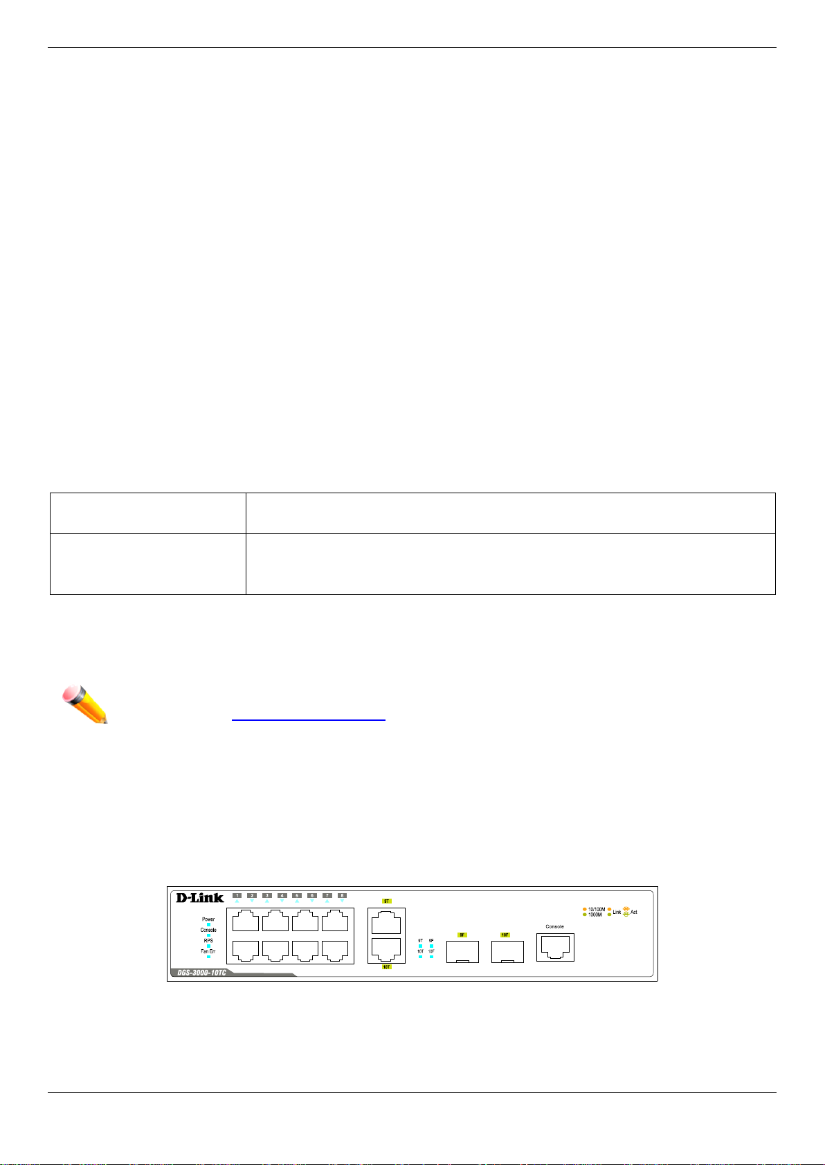
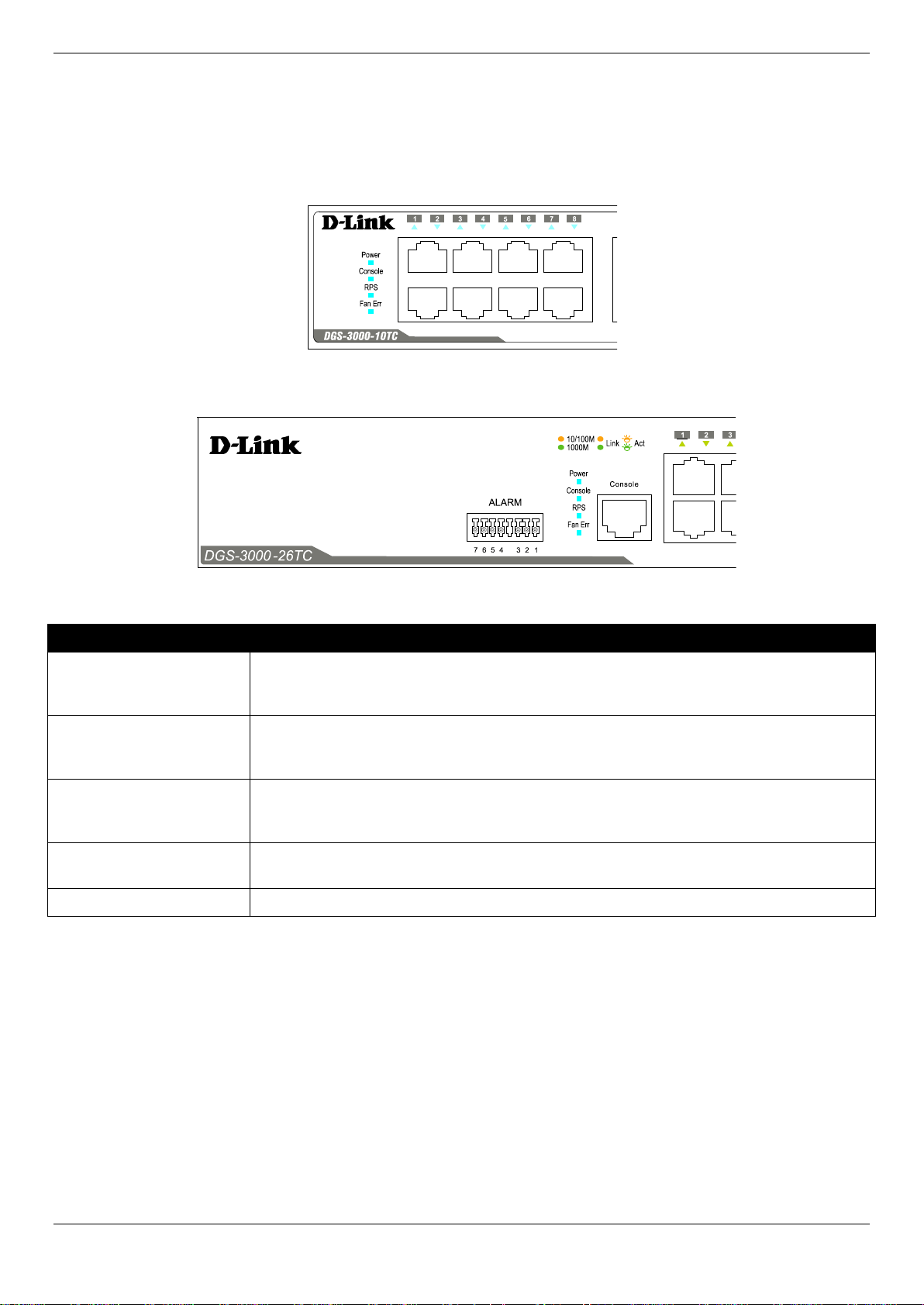
Front Panel Components
The front panel of the Switch consists of LED indicators for Power, Console, RPS, Fan Err, and for Link/Act for each
port on the Switch including SFP port LEDs. DGS-3000-26TC has an alarm port at the front panel.
Figure 1-1 Front panel view of the DGS-3000-10TC
3
Page 12
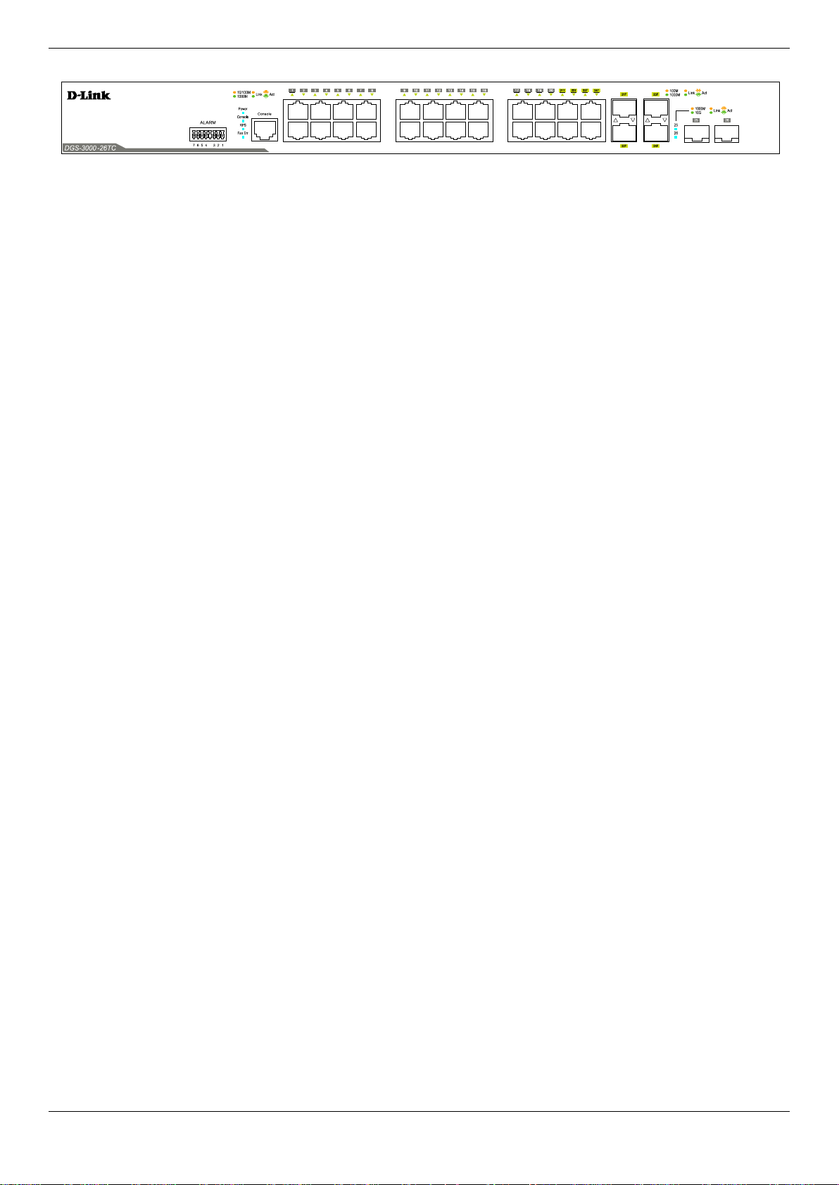
DGS-3000 Series Layer 2 Managed Gigabit Switch Hardware Installation Guide
Figure 1-2 Front panel view of the DGS-3000-26TC
4
Page 13
DGS-3000 Series Layer 2 Managed Gigabit Switch Hardware Installation Guide
LED Indicators
The Switch front panel presents LED indicators for Power, Console, RPS, Fan Err, and Link/Act indicators for all ports
including the Gigabit Ethernet ports.
Figure 1-3 LED indicators for the DGS-3000-10TC
Figure 1-4 LED indicators for the DGS-3000-26TC
LED Description
Power
Console
RPS
This LED lights green after powering the Switch on to indicate the ready state of the
device. The indicator is dark when the Switch is no longer receiving power (i.e. powered
off).
This LED blinks green during the Power-On Self Test (POST). When the POST is
finished, the LED goes dark. The indicator lights steady green when a user is logged in
through the console port.
This LED lights green if the Redundant Power Supply (RPS) is connected, the RPS
switch is turned on. If the indicator is off, the RPS is not connected or the RPS switch is
turned off.
Fan Err
Link/Act LEDs
This LED blinks red when any of the fans has failed. No light indicates all fans are
working normally.
The Switch has LED indicators for Link and Activity.
5
Page 14
DGS-3000 Series Layer 2 Managed Gigabit Switch Hardware Installation Guide
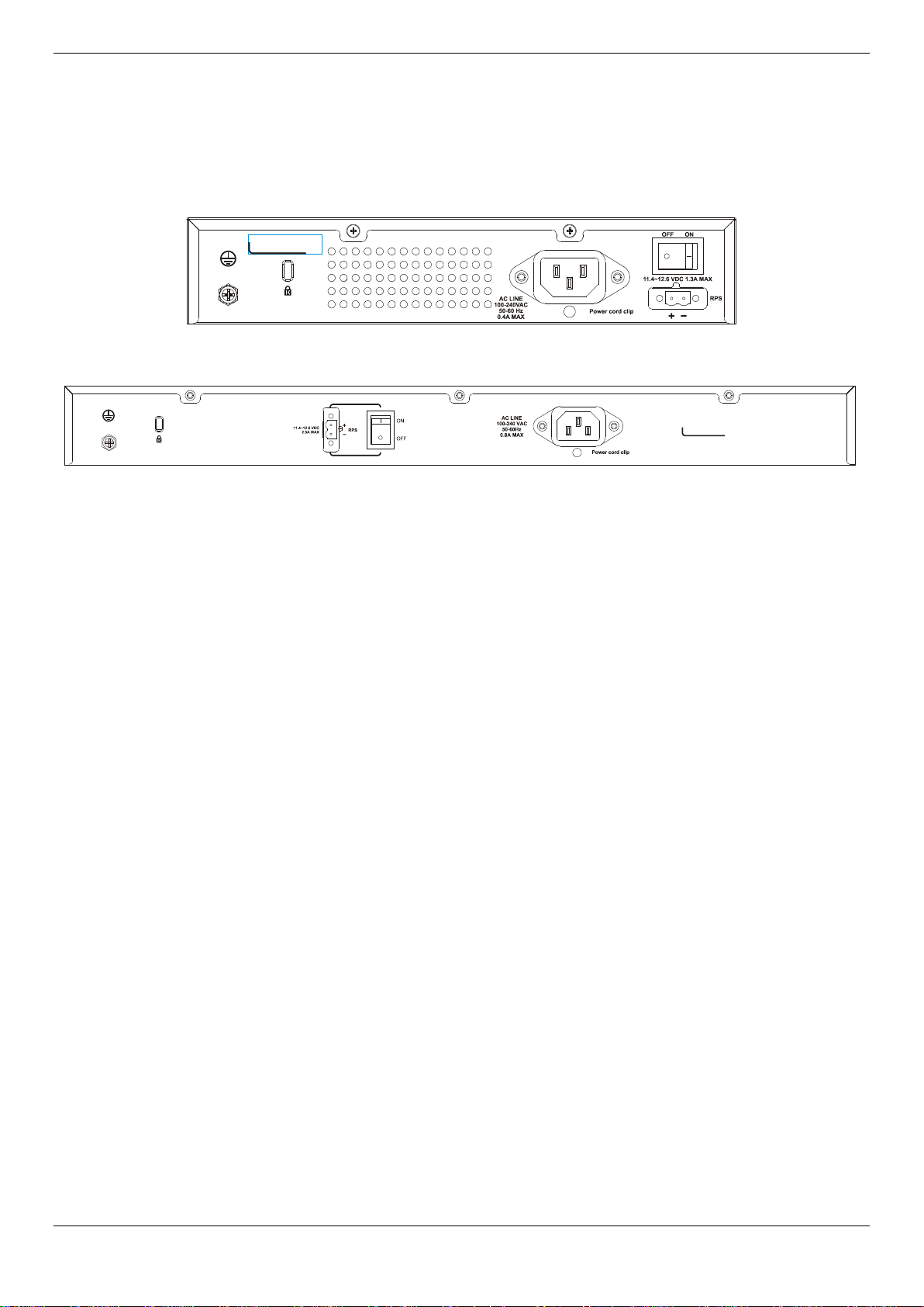
Rear Panel Description
The rear panel contains an AC power socket, an ON/OFF toggle switch, an outlet for an external redundant power
supply or a DC power supply, and security lock.
Figure 1-5 Rear panel view of the DGS-3000-10TC
Figure 1-6 Rear panel view of the DGS-3000-26TC
The AC power socket is a standard three-pronged connector that supports the power cord. Plug-in the female
connector of the provided power cord into this socket, and the male side of the cord into a power outlet. The Switch
automatically adjusts the power setting to any supply voltage in the range from 100 to 240 VAC at 50 to 60 Hz. An
optional external Redundant Power Supply (DPS-200) can be plugged into the RPS outlet displayed above. When the
internal power fails, this optional external RPS will take over all the power immediately and automatically.
6
Page 15
DGS-3000 Series Layer 2 Managed Gigabit Switch Hardware Installation Guide
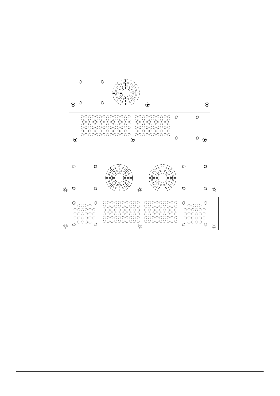
Side Panel Description
The system heat vents located on each side dissipate heat. Do not block these openings. Leave at least 6 inches of
space at the rear and sides of the Switch for proper ventilation. Be reminded that without proper heat dissipation and
air circulation, system components might overheat, which could lead to system failure or even severely damage
components.
Figure 1-7 Identical side panels of the DGS-3000-10TC
Figure 1-8 Identical side panels of the DGS-3000-26TC
7
Page 16

DGS-3000 Series Layer 2 Managed Gigabit Switch Hardware Installation Guide
Chapter 2 Installation
Package Contents
Installation Guidelines
Power On (AC Pow e r)
Alarm Connector (DGS-3000-26TC Only)
Installing Power Cord Clip
Installing SFP and SFP+ Ports
Connecting the DPS-2000 to the RPS Port
Installing the RPS into a Rack-mountChassis
Package Contents
Open the shipping carton of the Switch and carefully unpack its contents. The carton should contain the following
items:
• One DGS-3000 Series Switch
• One Quick Installation Guide
• AC power cord(s)
• One DC power source connector
• One RJ-45 to RS-232 console
• One set of Power Cord Clip
• One mounting kit (two brackets and screws)
• Four rubber feet with adhesive backing
• One CD kit for Web UI Reference Guide, CLI Reference Guide, and D-View module
If any item is missing or damaged, please contact your local D-Link reseller for replacement.
Installation Guidelines
Please follow these guidelines for setting up the Switch:
• Install the Switch on a sturdy, level surface that can support at least 13.9 lb. (6.3 kg) of weight. Do not place
heavy objects on the Switch.
• The power outlet should be within 1.82 meters (6 feet) of the Switch.
• Visually inspect the power cord and see that it is fully secur ed to the AC power p or t.
• Make sure that there is proper heat dissipation from and adequate ventilation around the Switch. Leave at
least 10 cm (4 inches) of space at the front and rear of the Switch for ventilation.
• Install the Switch in a fairly cool and dry place for the acceptable temperature and humidity operating ranges.
• Install the Switch in a site free from strong electromagnetic field generators (such as motors), vibration, dust,
and direct exposure to sunlight.
• When installing the Switch on a level surface, attach the rubber feet to the bottom of the device. The rubber
feet cushion the Switch, protect the casing from scratches and prevent it from scratching other surfaces.
8
Page 17

DGS-3000 Series Layer 2 Managed Gigabit Switch Hardware Installation Guide
Installing the Switch without a Rack
First, attach the rubber feet included with the Switch if installing on a desktop or shelf. Attach these cushioning feet on
the bottom at each corner of the device. Allow enough ventilation space between the Switch and any other objects in
the vicinity.
Figure 2-1 Prepare the Switch for installation on a desktop or shelf
Attaching Brackets to a Switch for Rack Mounting
The Switch can be mounted in a standard 19" rack using the provided mounting brackets. Use the following diagrams
as a guide.
Figure 2-2 Fasten mounting brackets on the Switch
Fasten the mounting brackets to the Switch using the screws provided. With the brackets attached securely, the
Switch can be mounted in a standard rack, as shown below.
NOTE: Please review the Installation Guidelines above before installing the Switch in a rack. Make
sure there is adequate space around the Switch to allow for proper air flow, ventilation, and
cooling.
9
Page 18

DGS-3000 Series Layer 2 Managed Gigabit Switch Hardware Installation Guide
CAUTION: Installing systems in a rack without the front and side stabilizers installed could cause the
Mounting the Switch in a Standard 19" Rack
Figure 2-3 Installing the Switch in a rack
Power On (AC Power)
1. Plug one end of the AC power cord into the power socket of the Switch and the other end into the local power
source outlet.
2. After powering on the Switch, the LED indicators will momentarily blink green. This blinking of the LED
indicators represents a reset of the system.
Power Failure (AC Power)
For AC power supply units, as a precaution, in the event of a power failure, unplug the Switch. When power has
resumed, plug the Switch back in.
rack to tip over, potentially resulting in bodily injury under certain circumstances. Therefore, always
install the stabilizers before installing components in the rack. After installing components in a rack, do
not pull more than one component out of the rack on its slide assemblies at one time. The weight of
more than one extended component could cause the rack to tip over and may result in injury.
Connecting a DC Power Supply
The Switch provides a DC power source connector to connect to any DC power source. The DC power source must
meet the following requirements:
• The DC power source's output voltage must be between 11.4V and 12.6V.
• The DC power source's output current rate must be higher or equal to 2.5A.
• Voltage protection must be apllied when the voltage is higher or equal to 15V.
• Current protection must be apllied when the current is higher or equal to 6A.
10
Page 19

DGS-3000 Series Layer 2 Managed Gigabit Switch Hardware Installation Guide
Figure 2-4 Connecting a DC power source to the Switch
1. Make sure that the ON/OFF toggle switch on the rear panel of the Switch is turned off.
2. Connect one end of the DC power cords supplied to a DC power source that will be activated when the AC
power is not working. Make sure that connection polarity (positive and negative) is correct at both sides before
using this feature to avoid any damaged.
3. Connect the other end of the DC power cords to the DC power source connector.
4. Connect the DC power source connector to the switch.
5. Turn the ON/OFF toggle switch on.
Alarm Connector (DGS-3000-26TC Only)
The alarm connector can be used to use external devices when triggered events occur.
11
Page 20

DGS-3000 Series Layer 2 Managed Gigabit Switch Hardware Installation Guide
1
Output. Normal Closed Pin. (42VAC or 60VDC)
2
Output. Common Pin. (42VAC or 60VDC)
3
Output. Normal Open Pin. (42VAC or 60VDC)
4
Input 2
5
Input 2
6
Input 1
7
Input 1
Figure 2-5 Alarm Connector
The following table describes the alarm connector port pin layout.
Contact Description
Connect the alarm input pins to alarm output terminals on other pieces of equipment.
Connect the alarm output pins to alarm input terminals on other pieces of equipment.
12
Page 21

DGS-3000 Series Layer 2 Managed Gigabit Switch Hardware Installation Guide
Installing Power Cord Clip
To prevent accidental removal of the AC power cord, it is recommended to install the power cord clip together with the
power cord.
1. With the rough side facing down, insert the Tie Wrap into the hole below the power socket.
Figure 2-6 Insert Tie Wrap to the Switch
2. Plug the AC power cord into the power socket of the Switch.
Figure 2-7 Connect the power cord to the Switch
13
Page 22

DGS-3000 Series Layer 2 Managed Gigabit Switch Hardware Installation Guide
3. Slide the Retainer through the Tie Wrap until the end of the cord.
Figure 2-8 Slide the Retainer through the Tie Wrap
4. Circle the tie of the Retainer around the power cord and into the locker of the Retainer.
Figure 2-9 Circle around the power cord
14
Page 23

DGS-3000 Series Layer 2 Managed Gigabit Switch Hardware Installation Guide
5. Fasten the tie of the Retainer until the power cord is secured.
Figure 2-10 Secure the power cord
15
Page 24

DGS-3000 Series Layer 2 Managed Gigabit Switch Hardware Installation Guide
Installing SFP and SFP+ Ports
The Switch is equipped with SFP (Small Form Factor Portable) and SFP+ ports, which are used with fiber-optical
transceiver cabling.SFP ports support full-duplex transmissions, auto-negotiation, and can be uplinked with various
other switches across a gigabit network. The SFP ports support data rates of up to 1Gbit/s and the SFP+ ports
support data rates of up to 10Gbit/s.
See the figure below for installing the SFP ports in the Switch.
Figure 2-11 Inserting fiber-optic transceivers into the Switch
For a full list of supported transceivers, compatible with this switch series, refer to Port Functions
.
16
Page 25

DGS-3000 Series Layer 2 Managed Gigabit Switch Hardware Installation Guide
Connecting the DPS-200 to the RPS Port
The DPS-200 redundant power supply can be connected to the RPS port of the Switch using the DC power supply
cord, called the DPS-CB150-2PS. It is important to notice that the DPS-200 can supply power to one or two
-300
DGS
0 at the same time.
Figure 2-12 Connecting two Swtiches to the DPS-200
The following section explaines how to connect the DPS-200 to the Switch.
1. Disconnect the Switch from the main AC power source.
2. Insert the 14-pin end of the DPS-CB150-2PS into the DPS-200 and the 2-pin end into the receptacle of the
RPS port on the Switch.
3. Using a standard AC power cord, connect the DPS-200 to the main AC power source. A green LED on the
front panel of the DPS-200 will illuminate to indicate a successful connection.
4. Make sure that the ON/OFF toggle switch on the rear panel of the Switch is turned on.
5. Re-connect the Switch to the AC power source and power on the DPS-200.
No configuration is needed in the Switch software for this installation.
NOTE: See the DPS-200 Quick Installation Guide for more information.
17
Page 26

DGS-3000 Series Layer 2 Managed Gigabit Switch Hardware Installation Guide
Installing the RPS into a Rack-mount Chassis
The DPS-200 is the redundant power supply unit designed to conform to the voltage requirements of the RPS port of
the Switch being supported. The DPS-200 can be installed into a DPS-800 and a DPS-900 rack-mount chassis unit.
CAUTION: DO NOT connect the RPS to the AC power before the DC power cable is connected.
Connecting the AC power before the DC power is connected might damage the internal power supply.
DPS-800 Rack-mount Chassis
The DPS-800 is a standard-size rack-mount (1 standard unit in height) designed to hold up to two DPS-200 redundant
power supplies.
Figure 2-13 Installing the DPS-200 in the DPS-800
The DPS-800 rack-mount chassis can be mounted into a standard 19" rack. Use the following diagram to guide you.
18
Page 27

DGS-3000 Series Layer 2 Managed Gigabit Switch Hardware Installation Guide
Figure 2-14 Installing the DPS-800 into a rack
DPS-900 Rack-mount Chassis
The DPS-900 is a standard-size rack-mount (5 standard units in height) designed to hold up to eight DPS-200
redundant power supplies.
Figure 2-15 Inserting the DPS-200 into the DPS-900
The DPS-900 rack-mount chassis can be mounted into a standard 19" rack. Use the following diagram to guide you.
19
Page 28

DGS-3000 Series Layer 2 Managed Gigabit Switch Hardware Installation Guide
CAUTION: Installing systems in a rack without the front and side stabilizers installed could cause the
Figure 2-16 Installing the DPS-900 into a rack
rack to tip over, potentially resulting in bodily injury under certain circumstances. Therefore, always
install the stabilizers before installing components in the rack. After installing components in a rack, do
not pull more than one component out of the rack on its slide assemblies at one time. The weight of
more than one extended component could cause the rack to tip over and may result in injury.
20
Page 29

DGS-3000 Series Layer 2 Managed Gigabit Switch Hardware Installation Guide
Chapter 3 Connecting the Switch
Switch to End Node
Switch to Switch
Connecting To Network Backbone or Server
NOTE: All high-performance N-Way Ethernet ports can support both MDI-II and MDI-X connections.
Switch to End Node
End nodes include PCs outfitted with a 10, 100 or 1000 Mbps RJ-45 Ethernet Network Interface Card (NIC) and
routers. An end node connects to the Switch via a twisted-pair UTP/STP cable. Connect the end node to any of the
1000BASE-T ports of the Switch. The Link/Act LEDs for each Ethernet port will light green or amber when the link is
valid. A blinking LED indicates packet activity on that port.
Figure 3-1 Connecting the Switch to an end node
21
Page 30

DGS-3000 Series Layer 2 Managed Gigabit Switch Hardware Installation Guide
Switch to Switch
There is a great deal of flexibility on how connections are made using the appropriate cabling.
• Connect a 10BASE-T switch port to the Switch via a twisted-pair Category 3, 4 or 5 UTP/STP cable.
• Connect a 100BASE-TX switch port to the Switch via a twisted-pair Category 5 UTP/STP cable.
• Connect 1000BASE-T switch port to the Switch via a twisted pair Category 5e UTP/STP cable.
• Connect switch supporting a fiber-optic uplink to the Switch’s SFP/SFP+ ports via fiber-optic cabling. See
cabling guidelines in Appendix B for more information.
Figure 3-2 Connecting a Switch to another switch
22
Page 31

DGS-3000 Series Layer 2 Managed Gigabit Switch Hardware Installation Guide
Connecting to Network Backbone or Server
The combo SFP ports and the 1000BASE-T ports are ideal for uplinking to a network backbone, server or server farm.
The copper ports operate at a speed of 1000, 100 or 10Mbps in full or half duplex mode. The fiber-optic ports can
operate at both 100Mbps and 1000Mbps in full duplex mode.
Connections to the Gigabit Ethernet ports are made using a fiber-optic cable or Category 5e copper cable, depending
on the type of port. A valid connection is indicated when the Link LED is lit.
Figure 3-3 Connecting the Switch to a server
23
Page 32

DGS-3000 Series Layer 2 Managed Gigabit Switch Hardware Installation Guide
Chapter 4 Introduction to Switch
Management
Management Options
Connecting the Console Port
First Time Connecting to the Switch
Password Protection
IP Address Assignment
SNMP Settings
Management Options
This system may be managed out-of-band through the console port on the front panel or in-band using Telnet. The
user may also choose the Web-based management, accessible through a Web browser.
Web-based Management Interface
After successfully installing the Switch, the user can configure the Switch, monitor the LED panel, and display
statistics graphically using a Web browser, such as Microsoft® Internet Explorer (version 5.5 and later), Netscape
(version 8 and later), Mozilla Firefox (version 2.0 and later), Safari (version 4.0 and later), and Google Chrome
(version 6.0 and later).
SNMP-based Management
The Switch can be managed with an SNMP-compatible console program. The Switch supports SNMP version 1.0,
version 2.0 and version 3.0. The SNMP agent decodes the incoming SNMP messages and responds to requests with
MIB objects stored in the database. The SNMP agent updates the MIB objects to generate statistics and counters.
Command Line Interface through the Serial Port or remote Telnet
The user can also connect a computer or terminal to the serial console port to access the Switch. The command line
interface provides complete access to all Switch management features.
Connecting the Console Port
The front panel of the Switch provides a port that enables a connection to a computer monitoring and configuring the
Switch. The console port is an RJ-45 port and requires a special cable that is included with the Switch, to establish the
physical connection.
To use the console port, the following equipment is needed:
• A terminal or a computer with both an RS-232 serial port and the ability to emulate a terminal.
• A console cable with a male DB-9 connector on one end and an RJ-45 connection on the other. This cable
should be included with the Switch. It establishes the physical connection to the console port.
To connect a terminal to the console port:
Connect the male DB-9 connector on the console cable (shipped with the Switch) to the RS-232 serial port on the
computer running terminal emulation software then insert the RJ-45 connector into the RJ-45 console port on the front
of the Switch. Set the terminal emulation software as follows:
• Select the appropriate serial port (COM port 1 or COM port 2).
• Set the data rate to 115200 baud.
• Set the data format to 8 data bits, 1 stop bit, and no parity.
• Set flow control to None.
24
Page 33

DGS-3000 Series Layer 2 Managed Gigabit Switch Hardware Installation Guide
NOTE:
• Under Properties, select VT100 for Emulation mode.
• Select Terminal keys for Function, Arrow and Ctrl keys. Make sure to use Terminal keys (not Windows keys)
are selected.
When using HyperTerminal with the Microsoft® Windows® 2000 operating system, ensure that
Windows 2000 Service Pack 2 or later is installed. Windows 2000 Service Pack 2 allows use of arrow
keys in HyperTerminal's VT100 emulation. See www.microsoft.com for information on Windows 2000
service packs.
• After you have correctly set up the terminal, plug the power cord into the power receptacle on the back of the
Switch. The boot sequence appears in the terminal.
• After the boot sequence completes, the console login screen displays.
• If the user has not logged into the command line interface (CLI) program, press the Enter key at the User
name and password prompts. There is no default user name and password for the Switch. The administrator
must first create user names and passwords. If user accounts have been previously set up, log in and
continue to configure the Switch.
• Enter the commands to complete desired tasks. Many commands require administrator-level access
privileges. Read the next section for more information on setting up user accounts. See the DGS-3000 Series
CLI Reference Guide on the documentation CD for a list of all commands and additional information on using
the CLI.
• To end a management session, use the logout command or close the emulator program.
If problems occur in making this connection on a PC, make sure the emulation is set to VT-100. The emulation
settings can be configured by clicking on the File menu in the HyperTerminal window by clicking on Properties in the
drop-down menu, and then clicking the Settings tab. This is where you will find the Emulation options. If you still do not
see anything, try rebooting the Switch by disconnecting its power supply.
Once connected to the console, the screen on the next page will appear on the console. This is where the user will
enter commands to perform all the available management functions. The Switch will prompt the user to enter a user
name and a password. Upon the initial connection, there is no user name or password and therefore just press Enter
twice to access the command line interface.
Boot Procedure V1.00.001
-------------------------------------------------------------------------------
Power On Self Test ........................................ 100 %
MAC Address : 00-01-02-03-04-00
H/W Version : A1
Please Wait, Loading V1.00.004 Runtime Image .............. 100 %
UART init ................................................. 100 %
Starting runtime image
Device Discovery .......................................... |
Figure 4-1 Boot up display in console screen
25
Page 34

DGS-3000 Series Layer 2 Managed Gigabit Switch Hardware Installation Guide
First Time Connecting to the Switch
The Switch supports user-based security that can allow prevention of unauthorized users from accessing the Switch
or changing its settings. This section tells how to log onto the Switch via out-of-band console connection or out-ofband Management port connection.
Upon initial connection to the Switch, the login screen appears (see example below).
DGS-3000-26TC Gigabit Ethernet Switch
Command Line Interface
Firmware: Build 1.00.004
Copyright(C) 2012 D-Link Corporation. All rights reserved.
UserName:
Figure 4-2 Initial screen, first time connecting to the Switch
Press Enter in both the Username and Password fields. Then access will be given to enter commands after the
command prompt DGS-3000-26TC:admin#
There is no initial username or password. Leave the Username and Password fields blank.
NOTE: The first user automatically gets Administrator level privileges. At least one Admin-level user
account must be created for the Switch.
Password Protection
The Switch does not have a default user name and password. One of the first tasks when settings up the Switch is to
create user accounts. Logging in using a predefined administrator-level user name will give the user privileged access
to the Switch's management software.
After the initial lo g in, define new passwords for both default user names to prevent unauthorized access to the Switch,
and record the passwords for future reference.
To create an administrator-level account for the Switch, do the following:
1. At the CLI login prompt, enter create account admin followed by the <user name> and press the Enter
key.
2. The Switch will then prompt the user to provide a password. Type the <password> used for the
administrator account being created and press the Enter key.
3. Once entered, the Switch will again ask the user to enter the same password again to verify it. Type the
same password and press the Enter key.
4. A “Success” response by the Switch will verify the creation of the new administrator.
NOTE: Passwords are case sensitive. User names and passwords can be up to 15 characters in
length.
26
Page 35

DGS-3000 Series Layer 2 Managed Gigabit Switch Hardware Installation Guide
IP Address Assignment
An IP address must be assigned to each switch, which is used for communication with an SNMP network manager or
other TCP/IP application (for example BOOTP, TFTP). The Switch's default IP address is 10.90.90.90. The user may
change the default Switch IP address to meet the specification of your networking address scheme.
The Switch is also assigned a unique MAC address by the factory. This MAC address cannot be changed, and can be
found by entering the command "show switch" into the command line interface.
The Switch's MAC address also appears in the Device Information and System Information windows of the Webbased management interface. The IP address for the Switch must be set before using the Web-based manager. The
Switch IP address can be automatically set using BOOTP or DHCP protocols, in which case the actual address
assigned to the Switch must be known.
SNMP Settings
Simple Network Management Protocol (SNMP) is an OSI Layer 7 (Application Layer) designed specifically for
managing and monitoring network devices. SNMP enables network management stations to read and modify the
settings of gateways, routers, switches and other network devices. Use SNMP to configure system features for proper
operation, monitor performance and detect potential problems in the Switch, switch group or network.
Managed devices that support SNMP include software (referred to as an agent), which runs locally on the device. A
defined set of variables (managed objects) is maintained by the SNMP agent and used to manage the device. These
objects are defined in a Management Information Base (MIB), which provides a standard presentation of the
information controlled by the on-board SNM P age nt. S NMP def ines both the format of the MIB specifications and the
protocol used to access this information over the network.
The Switch supports SNMP versions 1, 2c, and 3. The administrator may specify which version of SNMP to use to
monitor and control the Switch. The three versions of SNMP vary in the level of security provided between the
management station and the network device.
In SNMP v1 and v2, user authentication is accomplished using 'community strings', which function like passwords.
The remote user SNMP application and the Switch SNMP must use the same community string. SNMP packets from
any station that has not been authenticated are ignored (dropped).
The default community strings for the Switch used for SNMP v1 and v2 management access are:
• public - Allows authorized management stations to retrieve MIB objects.
• private - Allows authorized management stations to retrieve and modify MIB objects.
SNMP v3 uses a more sophisticated authentication process that is separated into two parts. The first part is to
maintain a list of users and their attributes that are allowed to act as SNMP managers. The second part describes
what each user on that list can do as an SNMP manager.
The Switch allows groups of users to be listed and configured with a shared set of privileges. The SNMP version may
also be set for a listed group of SNMP managers. Thus, a group of SNMP managers can be created to view read-only
information or receive traps using SNMP v1 while assigning a higher level of security to another group, granting
read/write privileges using SNM P v3.
Using SNMP v3 individual users or groups of SNMP managers can be allowed to perform or be restricted from
performing specific SNMP management functions. The functions allowed or restricted are defined using the Object
Identifier (OID) associated with a specific MIB. An additional layer of security is available for SNMP v3 in that SNMP
messages may be encrypted. To read more about how to configure SNMP v3 settings for the Switch read the section
entitled Management.
27
Page 36

DGS-3000 Series Layer 2 Managed Gigabit Switch Hardware Installation Guide
Traps
Traps are messages that alert network personnel of events that occur on the Switch. The events can be as serious as
a reboot (someone accidentally turned OFF the Switch), or less serious like a port status change. The Switch
generates traps and sends them to the trap recipient (or network manager). Typical traps include trap messages for
Authentication Failure, Topology Change and Broadcast/Multicast Storm.
MIBs
The Switch in the Management Information Base (MIB) stores management and counter information. The Switch uses
the standard MIB-II Management Information Base module. Consequently, values for MIB objects can be retrieved
from any SNMP-based network management software. In addition to the standard MIB-II, the Switch also supports its
own proprietary enterprise MIB as an extended Management Information Base. The proprietary MIB may also be
retrieved by specifying the MIB Object Identifier. MIB values can be either read-only or read-write.
28
Page 37

DGS-3000 Series Layer 2 Managed Gigabit Switch Hardware Installation Guide
Chapter 5 Web-based Switch Configuration
Introduction
Logging onto the Web Manager
Web-based User Interface
Web Pages
Introduction
The software functions of the Switch can be managed, configured, and monitored via the embedded Web-based
(HTML) interface. Manage the Switch from remote stations anywhere on the network through a standard bro w ser ,
such as Internet Explorer (version 5.5 and later), Netscape (version 8.0 and later), Mozilla Firefox (version 2.0 and
later), Safari (version 4.0 and later), or Google Chrome (version 6.0 and later). The browser acts as a universal access
tool and can communicate directly with the Switch using the HTTP protocol.
Logging onto the Web Manager
To begin managing the Switch, simply run the browser installed on your computer and point it to the IP address you
have defined for the device. The URL in the address bar should read something like: http://123.123.123.123, where
the numbers 123 represent the IP address of the Switch.
NOTE: The factory default IP address is 10.90.90.90.
This opens the management module's user authentication window, as seen below.
Figure 5-1 Enter Network Password window
As there is no default User name or Password, click OK to proceed. This will open the Web-based user interface. The
Switch management features available in the Web-based manager are explained below.
29
Page 38

DGS-3000 Series Layer 2 Managed Gigabit Switch Hardware Installation Guide
Select the menu or window to display. Open folders and click the hyperlinked menu buttons and
Presents a graphical near real-time image of the front panel of the Switch. This area displays the
AREA 2
AREA 1
AREA 3
Web-based User Interface
The user interface provides access to various Switch configuration and management windows, allows the user to view
performance statistics, and permits graphical monitoring of the system status.
Areas of the User Interface
The figure below shows the user interface. Three distinct areas divide the user interface, as described in the table.
Figure 5-2 Main Web Manager window
Area Number Function
Area 1
Area 2
Area 3
subfolders contained within them to display menus. Click the D-Link logo to go to the D-Link
website.
Switch's ports, console and management port, showing port activity.
Some management functions, including save, reboot, download and upload are accessible here.
Presents switch information based on user selection and the entry of configuration data.
30
Page 39

DGS-3000 Series Layer 2 Managed Gigabit Switch Hardware Installation Guide
Web Pages
When connecting to the management mode of the Switch with a Web browser, a login screen is displayed. There is no
default user name or password necessary to access the Switch's management mode.
NOTE: Be sure to configure the user name and password in the User Accounts window before
connecting the Switch to the greater network.
31
Page 40

DGS-3000 Series Layer 2 Managed Gigabit Switch Hardware Installation Guide
Appendix Section
Appendix A – Technical Specifications
General
Feature Detailed Description
Standards
Protocols
Data Transfer Rates:
Ethernet
Fast Ethernet
Gigabit Ethernet
10 Gigabit Ethernet
Network Cables
IEEE 802.1D/2004/Spanning Tree (802.1s, 802.1w)
IEEE 802.1Q-2005 VLAN
IEEE 802.1p Priority Queues
IEEE 802.1X Network Access Control
IEEE 802.3 Nway Auto-negotiation
IEEE 802.3ad Link Aggregation Control
IEEE 802.3az Energy-Efficient Ethernet
IEEE 802.3 10BASE-T Ethernet
IEEE 802.3u 100BASE-TX Fast Ethernet
IEEE 802.3ab 1000BASE-T Gigabit Ethernet
IEEE 802.3z 1000BASE-T (SFP “Mini GBIC”)
IEEE 802.3ae 10GBASE-X/10GBASE-R/10GBASE-W
IEEE 802.3aq 10GBASE-LRM
CSMA/CD
Half-duplex Full-duplex
10 Mbps 20Mbps
100Mbps 200Mbps
------------- 2Gbps
------------- 20Gbps
Cat.5 Enhanced for 1000BASE-T
UTP Cat.5, Cat. 5 Enhanced for 100BASE-TX
UTP Cat.3, 4, 5 for 10BASE-T
EIA/TIA-568 100-ohm screened twisted-pair (STP)(100m)
Number of Ports
DGS-3000-10TC: Eight Copper ports (10/100/1000Mbps), Two Combo Copper/SFP
ports (10/100/1000Mbps and 100/1000Mbps).
DGS-3000-26TC: Twenty Copper ports (10/100/1000Mbps), Four Combo Copper/SFP
ports (10/100/1000Mbps and 100/1000Mbps), Two SFP+ ports (1000Mbps/10Gbps)
Physical and Environmental
Feature Detailed Description
Internal Power Supply
Optional Redundant
Power Supply
Security Lock
Power Consumption
AC Input: 100 – 240 VAC, 50-60 Hz
Provides one connector in rear panel to install optional external RPS to enhance the
reliability. When internal power is failed, the optional external RPS will take over all the
power immediately and automatically.
Provides a Kensington-compatible security lock, at the rear of the switch, to be able to
connect to a secure immovable device. Insert the lock into the notch and turn the key to
secure the lock. The lock-and-cable apparatus should be purchased separately.
DGS-3000-10TC: 16.5 Watts (Max.)
DGS-3000-26TC: 29.6 Watts (Max.)
32
Page 41

DGS-3000 Series Layer 2 Managed Gigabit Switch Hardware Installation Guide
Operating Temperature
Storage Temperature
Humidity
Dimensions
Weight
EMI/EMC; RF Certificates
and Test Reports
Safety Certificates and
Test Reports
0°C - 50°C
-40°C - 70°C
Operation: 10%-90% RH non-condensing
Storage: 5% - 90% RH non-condensing
DGS-3000-10TC: 228.5mm (W) x 195mm (D) x 44mm (H)
DGS-3000-26TC: 440mm (W) x 209.9mm (D) x 44mm (H)
DGS-3000-10TC: 1.1kg
DGS-3000-26TC: 2.0kg
CE Report (2004/108/EC), EN 55022:2006, EN 55024:1998+A1: 2001+A2:2003, EN
61000-3-2:2006, EN 61000-3-3 :1995+A1: 2001+A2: 2005, FCC report (FCC CFR 47
Part 15 B), IC report (ICES-003), C-Tick Report (AS/NZS CISPR 22), VCCI Report
(CISPR 22), BSMI(CNS 13438: 95-06-01 甲類 (完整版))
UL/CSA 60950-1, IEC60950-1: 2001, EN60950-1: 200 1, BSMI(CNS 14336-1 (民國 99 年
版))
Performance
Feature Detailed Description
Transmission Method
Store-and-forward
Packet Buffer
Maximum Forwarding
Rate
Switching Capability
Priority Queues
MAC Address Table
Wire Speed
Virtual Stacking /
Clustering
1.5 MByte (Max)
DGS-3000-10TC: 14.88 million packets per second.
DGS-3000-26TC: 65.48 million packets per second.
DGS-3000-10TC: 20Gbps
DGS-3000-26TC: 88Gbps
8 Priority Queues per port
Supports 16K MAC addresses
Full-wire speed (full-duplex) operation on all ports including Gigabit ports.
1. Support D-Link Single IP Management v1.6
2. Manage up to 32 devices in a virtual stack with a single IP address.
LED Indicators
Location LED Indicative Color Status Description
Per Device Power
Console
Green Solid Light Power on.
Light off Power off.
Green Solid Light Console on.
RPS
Fan Err
Light off Console off.
Green Solid Light RPS is connected and the RPS switch is
turned on.
Light off RPS is not connected or the RPS switch is
turned off.
Red Blinking When any of the fans has failed.
Light off When all fans work normally.
33
Page 42

DGS-3000 Series Layer 2 Managed Gigabit Switch Hardware Installation Guide
10/100/1000 Mbps
LED Per
Port
LED Per SFP Port Link/Act
Link/Act/Speed
Mode
Green Solid Light When there is a secure connection (or link)
to 1000Mbps Ethernet device at any of the
ports.
Blinking When there is reception or transmission of
data occurring at 1000Mbps.
Orange Solid Light When there is a secure connection (or link)
to 10/100Mbps Ethernet device at any of the
ports.
Blinking When there is reception or transmission of
data occurring at 10/100Mbps.
Off Light off No link.
Green Solid Light When there is a secure connection (or link)
to 1000Mbps Ethernet device at any of the
ports.
Blinking When there is reception or transmission of
data occurring at 1000Mbps.
Orange Solid Light When there is a secure connection (or link)
to 100Mbps Ethernet device at any of the
ports.
Blinking When there is reception or transmission of
data occurring at 100Mbps.
LED Per SFP+
Port
Link/Act
Off Light off No link.
Green Solid Light When there is a secure connection (or link)
to 10Gbps Ethernet device at any of the
ports.
Blinking When there is reception or transmission of
data occurring at 10Gbps.
Orange Solid Light When there is a secure connection (or link)
to 1Gbps Ethernet device at any of the
ports.
Blinking When there is reception or transmission of
data occurring at 1Gbps.
Off Light off No link.
34
Page 43

DGS-3000 Series Layer 2 Managed Gigabit Switch Hardware Installation Guide
Port Functions
Feature Detailed Description
Console Port
Copper Ports Compliant with the following standards:
SFP Ports Compliant with the following standards:
RJ-45 interface for Out-Of-Band (OOB) CLI configuration.
• IEEE 802.3 compliance
• IEEE 802.3u compliance
• IEEE 802.3ab compliance
• IEEE 802.3az compliance (100/1000Mpbs)
• Support Half/Full-Duplex operations
• Auto-negotiation
• Auto MDI/MDIX
• IEEE 802.3x Flow Control support for Full-Duplex mode, Back Pressure when Half-
Duplex mode, and Head-of-line blocking prevention
• IEEE 802.3z compliance
• IEEE 802.3x Flow Control support for Full-Duplex mode
• Support Auto-negotiation for Full-Duplex/ flow control operations
SFP Transceivers supported:
• DEM-310GT (1000BASE-LX, Single-mode, 10km)
• DEM-311GT (1000BASE-SX, Multi-mode, 550m)
• DEM-312GT2 (1000BASE-SX, Multi-mode, 2km)
• DEM-314GT (1000BASE-LHX, Single-mode, 50km)
• DEM-315GT (1000BASE-ZX, Single-mode, 80km)
• DEM-210 (100BASE-FX, Single-mode, 15km)
• DEM-211 (100BASE-FX, Multi-mode, 2km)
• DGS-712 (1000BASE-T, 1G Copper, 100m)
WDM transceivers supported:
• DEM-330T (1000BASE-BX, TX-1550/RX-1310nm, Single-mode, 10km)
• DEM-330R (1000BASE-BX, TX-1310/RX-1550nm, Single-mode, 10km)
• DEM-331T (1000BASE-BX, TX-1550/RX-1310nm, Single-mode, 40km)
• DEM-331R (1000BASE-BX, TX-1310/RX-1550nm, Single-mode, 40km)
• DEM-220T (100BASE-BX-D, TX-1550/RX-1310 nm, Single-mode, 20km)
• DEM-220R (100BASE-BX-U, TX-1310/RX-1550 nm, Single-mode, 20km)
SFP+ Ports (DGS-300026TC Only)
Compliant with the following standards:
• IEEE 802.3ae compliance
• IEEE 802.3aq compliance
SFP Transceivers supported:
• DEM-310GT (1000BASE-LX, Single-mode, 10km)
• DEM-311GT (1000BASE-SX, Multi-mode, 550m)
• DEM-312GT2 (1000BASE-SX, Multi-mode, 2km)
• DEM-314GT (1000BASE-LHX, Single-mode, 50km)
• DEM-315GT (1000BASE-ZX, Single-mode, 80km)
WDM transceivers supported:
35
Page 44

DGS-3000 Series Layer 2 Managed Gigabit Switch Hardware Installation Guide
• DEM-330T (1000BASE-BX, TX-1550/RX-1310nm, Single-mode, 10km)
• DEM-330R (1000BASE-BX, TX-1310/RX-1550nm, Single-mode, 10km)
• DEM-331T (1000BASE-BX, TX-1550/RX-1310nm, Single-mode, 40km)
• DEM-331R (1000BASE-BX, TX-1310/RX-1550nm, Single-mode, 40km)
SFP+ Transceivers supported:
• DEM-431XT (10GBASE-SR, (w/o DDM), 80m: OM1 & OM2 MMF, 300m: OM3
MMF)
• DEM-431XT-DD (10GBASE-SR, (with DDM), 80m: OM1 & OM2 MMF, 300m: OM3
MMF)
• DEM-432XT (10GBASE-LR, (w/o DDM), 10km)
• DEM-432XT-DD (10GBASE-LR, (with DDM), 10km)
• DEM-433XT (10GBASE-ER, (w/o DDM), 40km)
• DEM-433XT-DD (10GBASE-ER, (with DDM), 40km)
• DEM-435XT (10GBASE-LRM, (w/o DDM), 220m: OM1 & OM2 MMF, 300m: OM3
MMF)
• DEM-435XT-DD (10GBASE-LRM, (with DDM), 220m: OM1 & OM2 MMF, 300m:
OM3 MMF)
• DEM-436XT-BXU (10GBASE-LR, BiDi (w/o DDM), 20km, TX: 1270nm, RX:
1330nm)
• DEM-436XT-BXD (10GBASE-LR, BiDi (w/o DDM), 20km, TX: 1330nm, RX:
1270nm)
SFP+ Direct Attached Cables (DAC) supported:
• Direct Attached Cables are cables with built-in SFP+ transceivers at both ends.
• DEM-CB100S (10GbE SFP+ 1m Direct Attach Cable)
• DEM-CB300S (10GbE SFP+ 3m Direct Attach Cable)
RPS Port
• DEM-CB700S (10GbE SFP+ 7m Direct Attach Cable)
• Supports the connection to an external redundant power supply. In the event that
the AC internal power supply fails, the external RPS will take over the power supply.
Redundant Power Supplies (RPSs) and accessories supported:
• DPS-200 (60 Watt redundant power supply unit (includes RPSU cable and AC
power cord))
• DEM-CB150-2PS (1 DC input connector for DPS-200 and 2 DC outp ut con nectors
for the Switch)
Alarm Port (DGS-300026TC Only)
• Supports an alarm connector, on the front panel, that provides two external event
detection input circuits and one alarm action output circuit.
• Alarm action output circuit supports 42VAC, 50Hz, 1A maximum or 60VDC, 1A
maximum.
• After trap, log, and trigger events were generated by the Switch, pin 2 of the alarm
port is connected to pin 3 of the alarm port.
36
Page 45

DGS-3000 Series Layer 2 Managed Gigabit Switch Hardware Installation Guide
Appendix B – Cables and Connectors
Ethernet Cable
When connecting the Switch to another switch, a bridge or hub, a normal cable is necessary. Please review these
products for matching cable pin assignment.
The following diagrams and tables show the standard RJ-45 receptacle/connector and their pin assignments.
Figure B- 1. The standard RJ-45 port and connector
RJ-45 Pin Assignments
Contact MDI-X Port MDI-II Port
1
2
3
4
5
6
7
8
RD+ (receive) TD+ (transmit)
RD- (receive) TD- (transmit)
TD+ (transmit) RD+ (receive)
1000BASE-T 1000BASE-T
1000BASE-T 1000BASE-T
TD- (transmit) RD- (receive)
1000BASE-T 1000BASE-T
1000BASE-T 1000BASE-T
37
Page 46

DGS-3000 Series Layer 2 Managed Gigabit Switch Hardware Installation Guide
Console Cable
When connecting the Switch a PC, a Console cable is necessary. The following diagrams and tables show the
standard Console-to-DJ-45 receptacle/connector and their pin assignments.
Figure B- 2. Console-to-RJ-45 Cable
Console-RJ-45 Pin Assignments
Pin Console (DB9/RS232) RJ-45
1
2
3
4
5
6
7
8
Not Used Not Used
RXD Not Used
TXD TXD
Not Used GND
GND (shared) GND
Not Used RXD
Not Used Not Used
Not Used Not Used
38
Page 47

DGS-3000 Series Layer 2 Managed Gigabit Switch Hardware Installation Guide
Redundant Power Supply (RPS) Cable
When connecting the Switch to a Redundant Power Supply, an RPS cable is necessary. Please review these products
for matching cable pin assignment.The following diagrams and tables show the DPS-CB150-2PS
receptacle/connector and their pin assignments.
Figure B- 3. DPS-CB150-2PS Cable
RPS 14-pin to two 2-pin DC Power Cable Pin Assignments
Pin 2-pin 14-pin
1
2
3
4
5
6
7
8
9
10
11
12
13
14
GND GND
+12V NC
- +12V
- +12V
- +12V
- +12V
- GND
- GND
- Power Good
- Power Present
- NC
- NC
- GND
- GND
39
Page 48

Subject to the terms and conditions set forth herein, D-Link Systems, Inc. (“D-Link”) provides this Limited Warranty:
• Only to the person or entity that originally purchased the product from D-Link or its authorized reseller or distributor, and
• Only for products purchas ed and delivered within the fifty states of the United States, the District of Col umbia, U.S. Possessions or Protectorates,
U.S. Military Installations, or addresses with an APO or FPO.
Limited Warranty: D-Link warrants that the hardware portion of the D-Link product described below (“Hardware”) will be free from material defects in
workmanship and materials under normal use from the date of original retail purchase of the product, for the period set forth below (“W arranty Period”),
except as otherwise stated herein.
Limited Lifetime Warranty for the product is defined as follows:
• Hardware: For as long as the original customer/end user owns the product, or five (5) years after product discontinuance, whichever occurs first
(excluding power supplies and fans)
• Power supplies and fans: Three (3) Year
• Spare parts and spare kits: Ninety (90) days
The customer's sole and exclusive remedy and the entire liabili ty of D-Link and its suppliers under this Limited Warranty will be, at D-Li nk’s option, to
repair or replace the defective Hardware during the Warranty Period at no cha rge to the original owner or to refund the actual purcha se price paid. Any
repair or replacement will be rendered by D-Link at an Authorized D-Link Service Office. The replace m ent hardware n eed not be ne w or have an i dentic al
make, model or part. D-Link may, at its option, replace the defective Hardware or an y part thereof with any reconditioned product th at D-Link reasonabl y
determines is substantially equivalent (or superior) in all material respects to the defective Hardware. Repaired or replacement hardware will be
warranted for the remainder of the original Warranty Period or ninety (90) days, whichever is longer, and is subject to the same limitations and exclusio ns.
If a material defect is incapable of correction, or if D-Link determi nes that it is not practical to repair or replace the defective Hard ware, the actual price
paid by the original purchaser for the defective Hardware will be refunded by D-Link upon return to D-Link of the defective Hardware. All Hardware or part
thereof that is replaced by D-Link, or for which the purchase price is refunded, shall become the property of D-Link upon replacement or refund.
Limited Software Warranty: D-Link warrants that the software portion of the product (“Software”) will substantially conform to D-Link’s then current
functional specifications for the Software, as set forth in the applicable documentation, from the date of original retail purchase of the Software for a period
of ninety (90) days (“Software Warranty Period”), provided that the Software is properl y installed on approved hard ware and operated as c ontemplated in
its documentation. D-Link further warrants that, during the Software Warranty Period, the magnetic m edia on which D-Link delivers the Software will be
free of physical defects. The customer's sole and exclusive remedy and the entire liabili ty of D-Link and its suppliers under this Limi ted Warranty will be,
at D-Link’s option, to replace the non-conforming Software (or defective media) with software that substantially conforms to D-Link’s functional
specifications for the Software or to refund the portion of the actual purchase pric e paid that is attributable to the Softwa re. Except as otherwise agreed
by D-Link in writing, the replacement Software is provided onl y to the origi nal li censee, and i s s ubjec t to the terms and condi tions of the li cens e granted by
D-Link for the Software. Replacement Software will be warranted for the remainder of the ori ginal Warranty Period and is subj ect to the same limitations
and exclusions. If a material non-conformance is incapable of correction, or if D-Link determines in its sol e discretion that it is not practical to replace the
non-conforming Software, the price paid by the original licensee for the non-c onforming Software will be refunded by D-Link; provided that the nonconforming Software (and all copies thereof) is first returned to D-Link. The license granted respecting any Software for which a refund is given
automatically terminates.
Non-Applicability of Warranty: The Limited Warranty provided hereunder for Hardware and Software portions of D-Link's products will not be applied to
and does not cover any refurbished product and any product purchased through the inventory clearance or liquidation sale or other sales in which D-Link,
the sellers, or the liquidators expressly disclaim their warranty obligati on pertaining to the product and in that case, the product is being sold "As-Is"
without any warranty whatsoever incl uding, without limitation, the Limited Warranty as described herein, notwithstanding anything stated herein to the
contrary.
Submitting A Claim: The custo mer shall return the pro duct to the original purchase poi nt based on its return polic y. In case the retur n policy period has
expired and the product is within warranty, the customer shall submit a claim to D-Link as outlined below:
• The customer must submit with the product as part of the claim a written description of the Hard ware defec t or Soft ware nonconfo rma nc e in suffi ci ent
detail to allow D-Link to confirm the same, along with proof of purchas e of the product (such as a copy of the dated purchase invoice for the product )
if the product is not registered.
• The customer must obtain a Case ID Number from D-Link Technical Support at 1-877-453-5465, who will attempt to assist the customer in resolvi ng
any suspected defects with the product. If the product is considered defective, the customer mus t obtain a Return Material Authorization (“RMA”)
number by completing the RMA form and entering the assigned Case ID Number at
• After an RMA number is issued, the defective product mus t be packaged securely in the origi nal or other suitable shippi ng package to ensure that i t
will not be damaged in transit, and the RMA number must be prominently marked on the outside of the pack age. Do not include any manuals or
accessories in the shipping package. D-Link will only replace the defective portion of the product and will not ship back any accessories.
• The customer is responsible for all in-bound shipping charges to D-Link. No Cash on Delivery (“COD”) is al lowed. Products sent COD will either be
rejected by D-Link or become the property of D-Link. Products shall be fully insured by the customer and shipped to D-Link Systems, Inc., 17595
Mt. Herrmann, Fountain Valley, CA 92708. D-Link will not be held responsible for any packages that are l ost in transit to D-Link. The repair ed or
replaced packages will be shipped to the customer via UPS Ground or an y common carrier selected by D-Link. Return shipping charges shall be
prepaid by D-Link if you use an address in the United States, otherwise we will ship the product to you freight collec t. Expedited shipping is av ailable
upon request and provided shipping charges are prepaid by the customer.
D-Link may reject or return any product that is not packaged and shipped in strict compliance with the foregoing requirements, or for which an RMA
number is not visible from the outside of the package. The product owner agrees to pay D -Link’s reasonable handling and return shi pping c harges for an y
product that is not packaged and shipped in accordance with the foregoing requirements, or that is determined by D-Link not to be defec tive or nonconforming.
What Is Not Covered: The Limited Warranty provided herein by D-Link does not cover: Products that, in D-Link’s judgment, have been s ubjected to
abuse, accident, alteration, modification, tampering, negligence, misuse, faulty installation, lack of reasonabl e care, repair or servi ce in any way that is not
contemplated in the documentation for the product, or if the model or serial number has been altered, tampered with, defaced or removed; Initial
installation, installation and removal of the product for repair, and shipping costs; Operational adjustm ents c overed in the operating manual for the product,
and normal maintenance; Damage that occurs in shipment, due to act of God, failures due to power surge, and cosmetic damage; Any hardware,
software, firmware or other products or services provided by anyone other than D-Link; and Products that have been purchas ed from inventory clearanc e
or liquidation sales or other sales in which D-Link, the sellers, or the liquidators expressl y disclaim their warranty obligation pertaining to the product.
While necessary maintenance or repairs on your Product can be performed by any company, we recommend that you use only an Authorized D-Link
Service Office. Improper or incorrectly performed maintenance or repair voids this Limited Warranty.
Disclaimer of Other Warranties: EXCEPT FOR THE LIMITED WARRANTY SPE CIFIED HEREIN, THE PRODUCT IS PROVIDED “AS-IS” WI THOUT
ANY WARRANTY OF ANY KIND WHATSOEVER INCLUDING, WITHOUT LIMITATION, ANY WARRANT Y OF MERCHANTABILITY, FITNESS FOR A
PARTICULAR PURPOSE AND NON-INFRINGEMENT. IF ANY IMPLIED WARRANTY CANNOT BE DISCLAIMED IN ANY TERRITORY WHERE A
PRODUCT IS SOLD, THE DURATION OF SUCH IMPLIED WARRANTY SHALL BE LIMITED TO NINETY (90) DAYS. EXCEPT AS EXPRESSLY
COVERED UNDER THE LIMITED WARRANTY PROVIDED HEREIN, THE ENTIRE RISK AS TO THE QUALITY, SELECT ION AND PERFORMANCE
OF THE PRODUCT IS WITH THE PURCHASER OF THE PRODUCT.
https://rma.dlink.com/.
 Loading...