

Page 1
Getting Started Guide
Erste Schritte
Guide de démarrage
Guida introduttiva
Guía de introducción
Краткое руководство пользователя
快速安裝指南
Guia inicial
Petunjuk Pemasangan
本製品のご利用にあたって
Page 2
About This Guide
Rack Installation
This guide gives step-by-step instructions for setting up
all D-Link EasySmart switches. Please note that the
model you have purchased may appear slightly different
from those shown in the illustrations.
For more detailed information about your switch, its
components, making network connections, and technical
specifications, please refer to the User’s Guide included
with your switch.
Step 1 – Unpacking
Open the shipping carton and carefully unpack its
contents. Please consult the packing list located in the
User Guide to make sure all items are present and
undamaged. If any item is missing or damaged, please
contact your local D-Link reseller for replacement.
- One D-Link EasySmart Switch
- Rack mounting bracket
- Power cord
- User’s Guide CD with SmartConsole Utility program
- One multilingual Getting Started Guide
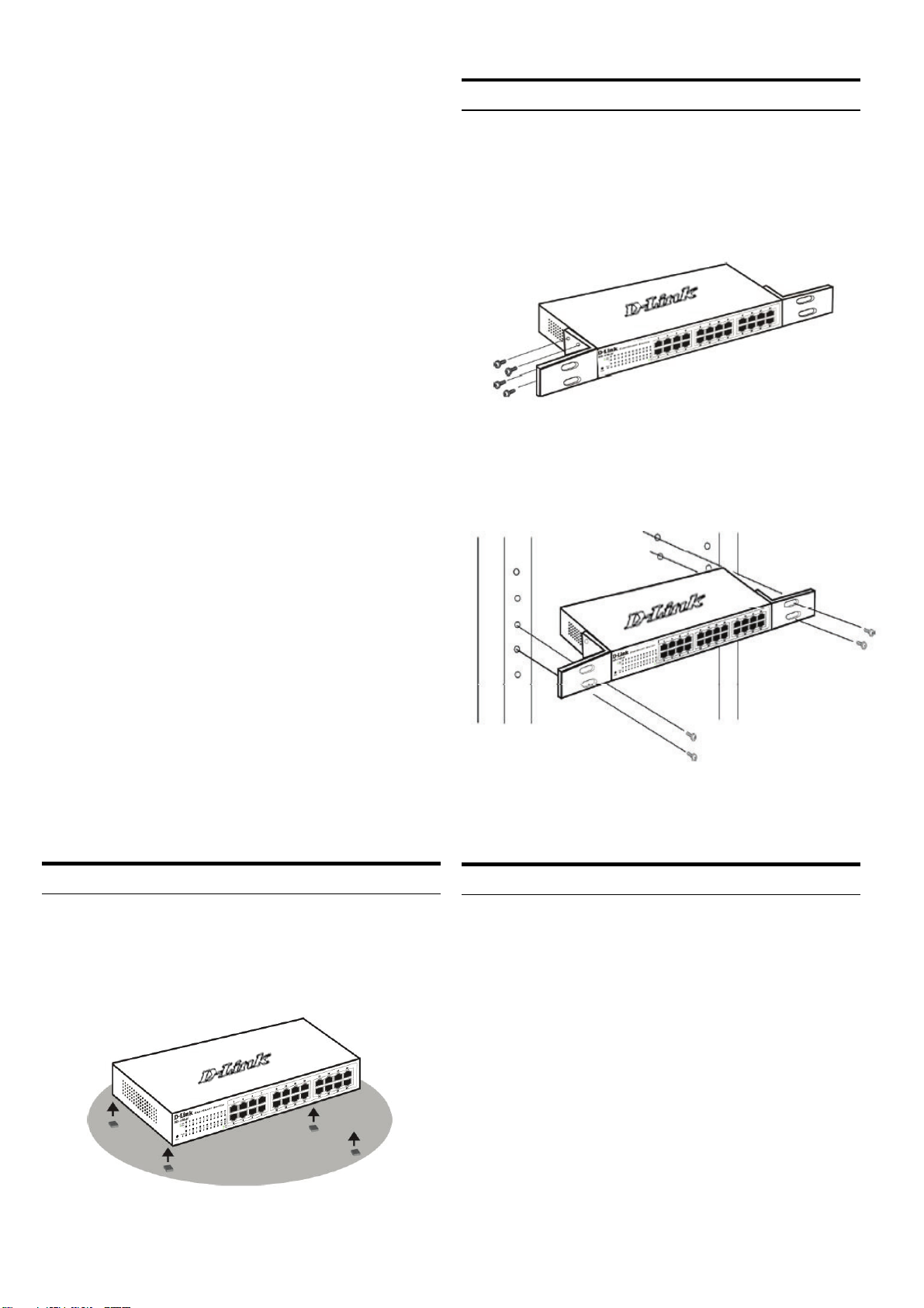
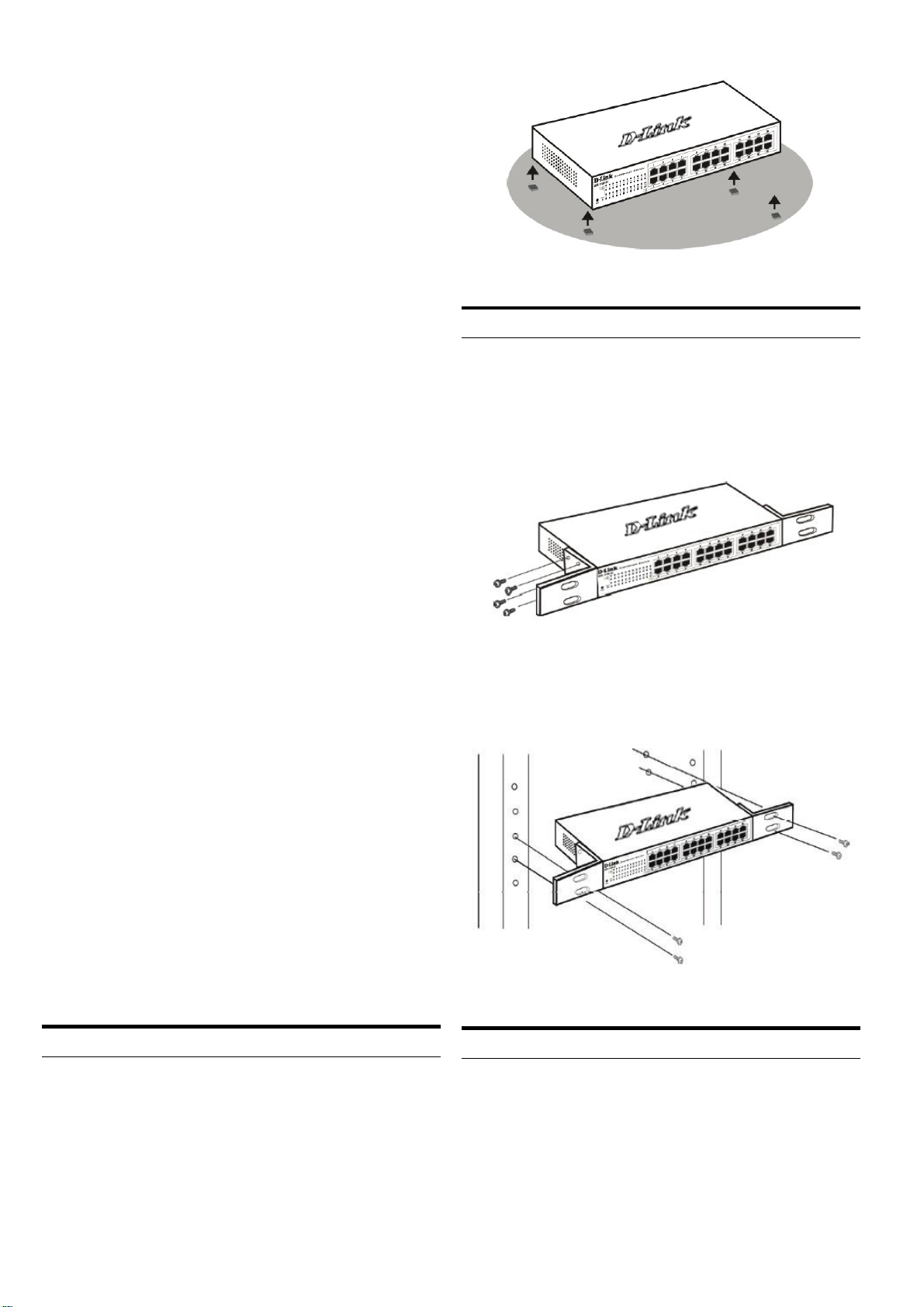
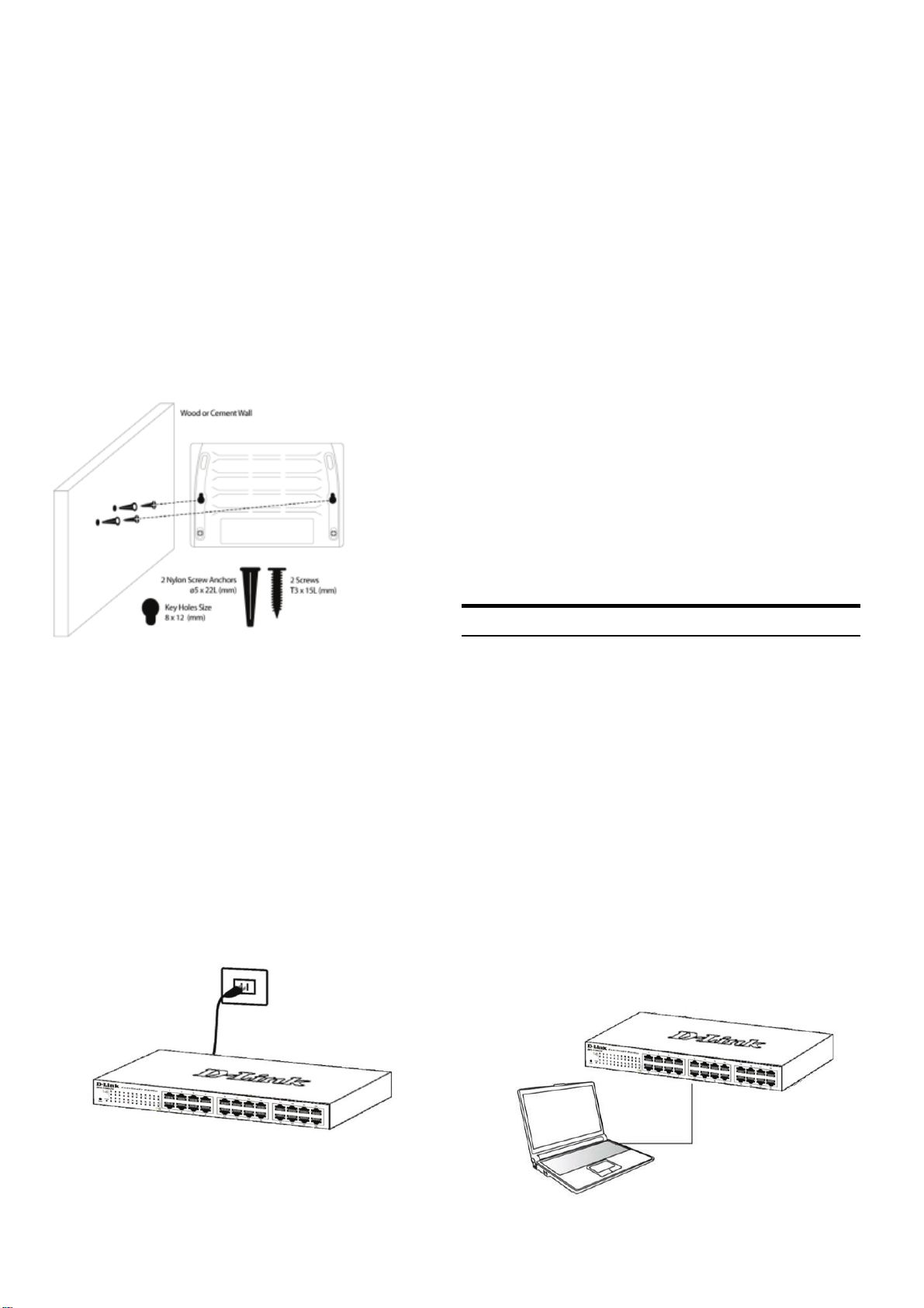
The switch can be mounted in an EIA standard size
11-inch rack, which can be placed in a wiring closet with
other equipment. To install, attach the mounting brackets
to the switch’s side panels (one on each side) and
secure them with the screws provided.
Figure 2. Attaching the mounting brackets
Then, use the screws provided with the equipment rack
to mount the switch in the rack.
- An accessory kit for one ground screw
Step 2 – Switch Installation
For safe switch installation and operation, it is
recommended that you:
♦ Visually inspect the power cord to see that it is
secured fully to the AC power connector
♦ Make sure that there is proper heat dissipation and
adequate ventilation around the switch
♦ Do not place heavy objects on the switch
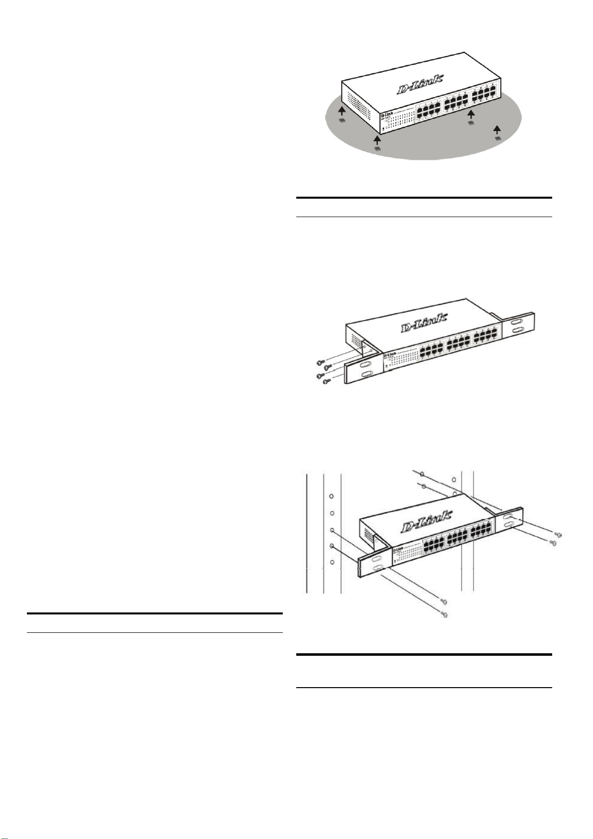
Desktop or Shelf Installation
When installing the switch on a desktop or shelf, the
rubber feet included with the device must be attached on
the bottom at each corner of the device’s base. Allow
enough ventilation space between the device and the
objects around it.
Figure 1. Attaching the rubber feet
Figure 3. Installing the switch in a standard-sized
equipment rack
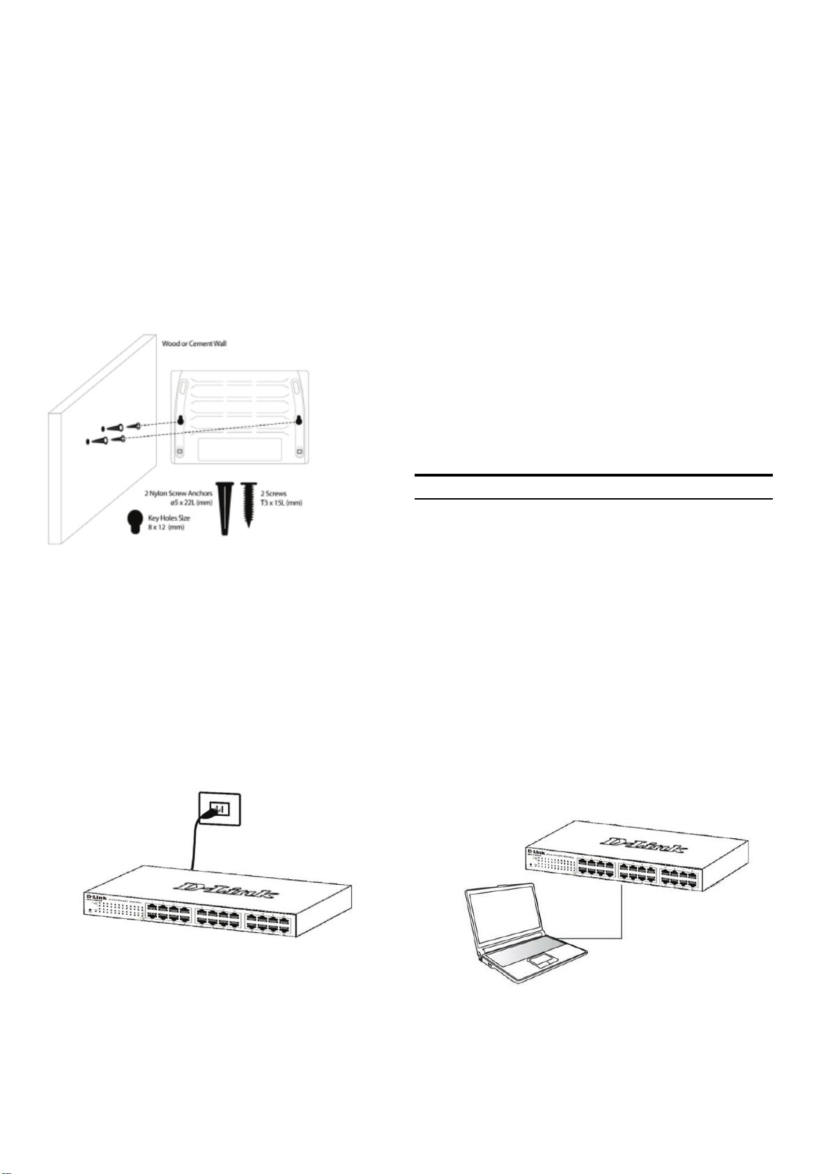
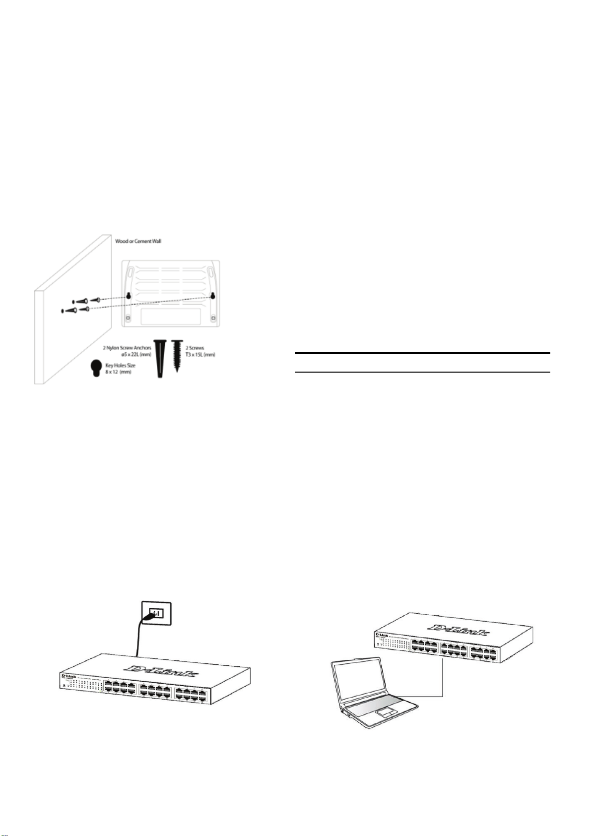
Mounting the Switch on a Wall (Wall-Mount)
The desktop size DGS-1100 switch can also be mounted
on a wall. Two mounting slots are provided on the bottom
of the switch for this purpose. Please make sure that the
front panel is exposed in order to view the LEDs. Please
refer to the illustrations below:
A.) Mounting on a concrete wall
1. Fix the nylon screw anchors into the concrete wall.
2. Drive the T3 x 15L screws into the nylon screw anchors.
3. Hook the witch with the mounting holes on the bottom
onto the screws, and it is completed.
B.) Mounting on a wooden wall
1. Drive the T3 x 15 L screws into the wooden wall.
2. Hook the witch with the mounting holes on the bottom
onto the screws, and it is completed.
2
Page 3
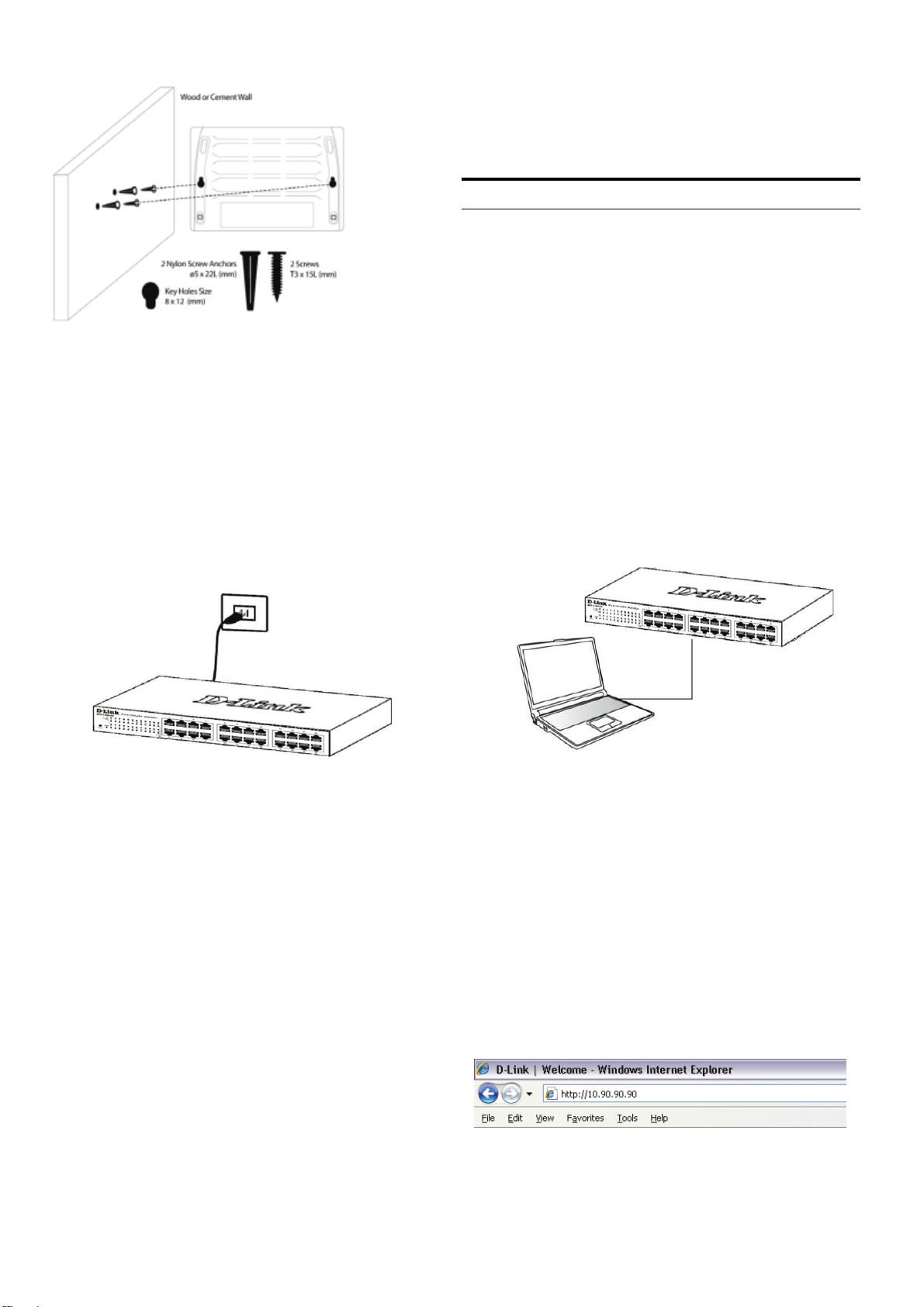
(1) 3/4 inch minimum for wooden wall.
(2) 3 inch minimum for concrete wall.
Figure 4. Mounting a desktop switch to a Wall
the IP address of your PC and it is easy to start the initial
setting of multiple EasySmart Switches.
Please refer to the following detailed installation instructions
for the Web-Based Management and SmartConsole Utility.
Web-based Management Interface
After a successful physical installation, you can configure
the switch, monitor the LED panel, and display statistics
graphically using a web browser, such as Netscape
Navigator (version 6.2 and higher) or Microsoft
Explorer (version 5.0 and higher).
You need the following equipment to begin the web
configuration of your device:
A PC with a RJ-45 Ethernet connection
A standard Ethernet cable
®
Internet
Step 3 – Plugging in the AC
Power Cord
You can now connect the AC power cord into the rear of
the switch and to an electrical outlet (preferably one that
is grounded and surge protected).
Figure 5. Plugging the switch into an outlet
Power Failure
As a precaution, the switch should be unplugged in case
of power failure. When power is resumed, plug the switch
back in.
Management Options
The D-Link EasySmart Switch can be managed through
a web browser or through any PC using the SmartConsole
Utility.
If you want to manage only one D-Link EasySmart Switch,
the Web-Based Management is the better option. Each
switch must be assigned its own IP Address, which is
used for communication with Web-Based Management
and the PC should have an IP address in the same
range as the switch.
However, if you want to manage multiple D-Link EasySmart
Switches, the SmartConsole Utility is the better option.
Using the SmartConsole Utility, you don’t need to change
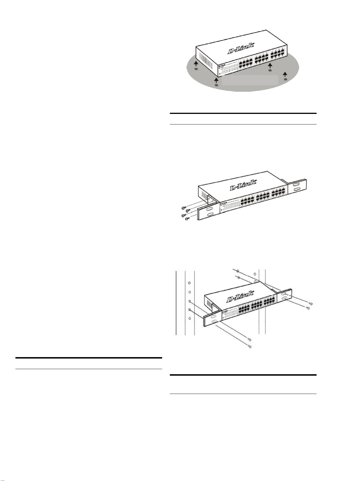
Step 1
Connect the Ethernet cable to any of the ports on the
front panel of the switch and to the Ethernet port on the
PC.
Figure 6. Connected Ethernet cable
Step 2
In order to login and configure the switch via an Ethernet
connection, the PC must have an IP address in the same
range as the switch. For example, if the switch has an IP
address of 10.90.90.90, the PC should have an IP address
of 10.x.y.z (where x/y is a number between 0 ~ 254 and z is
a number between 1 ~254), and a subnet mask of 255.0.0.0.
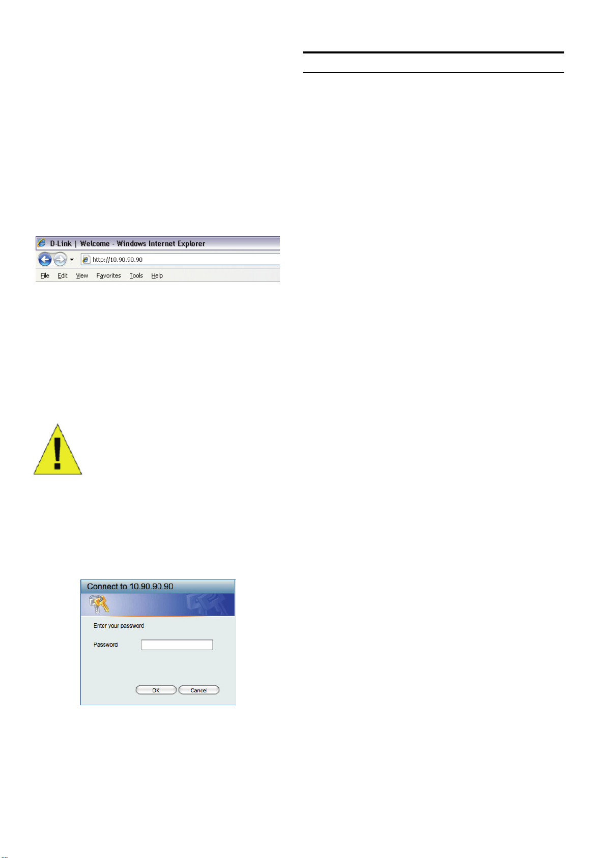
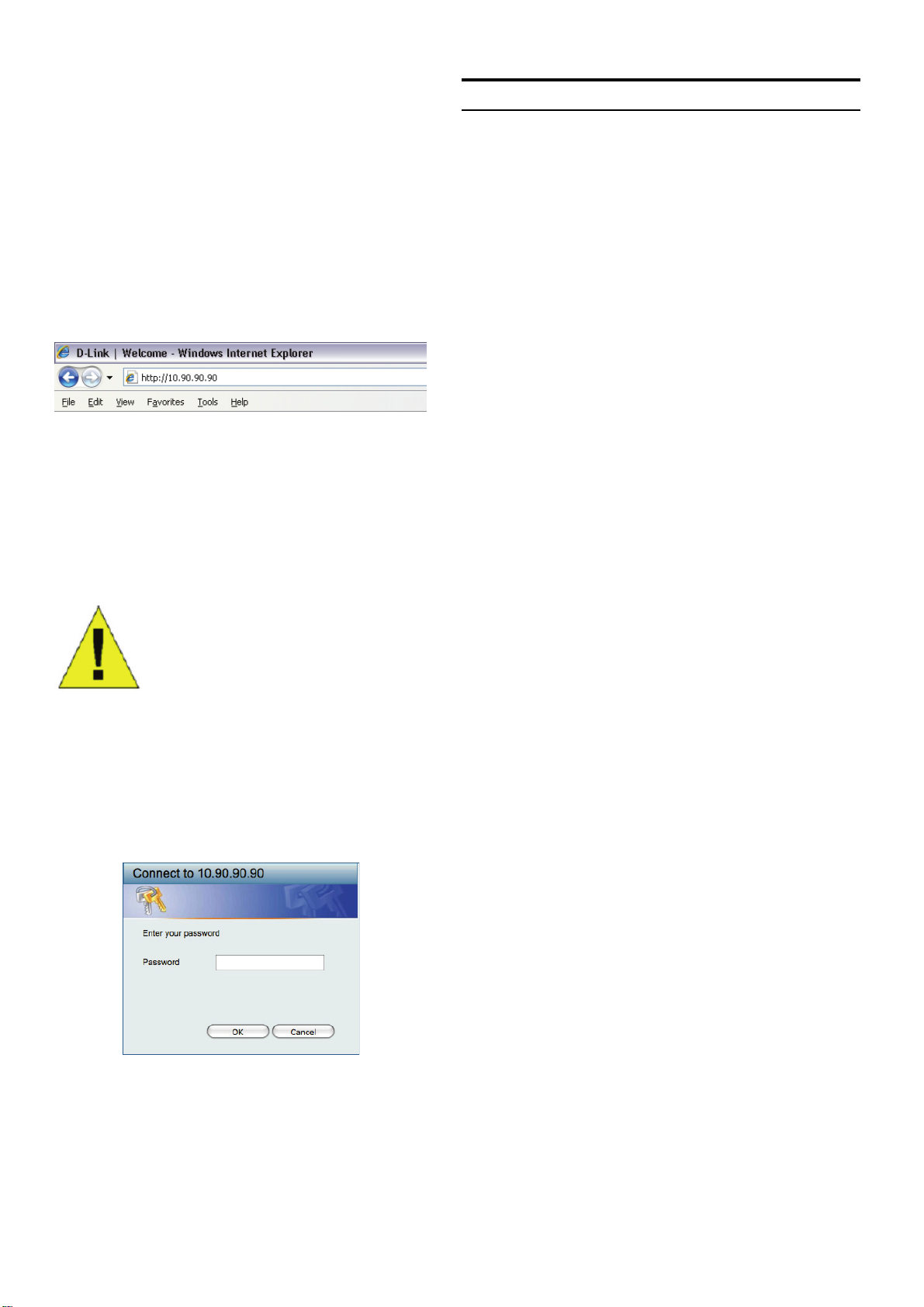
Open your web browser and enter http://10.90.90.90
(the factory-default IP address) in the address box. Then
press <Enter>.
Figure 7. Enter the IP address 10.90.90.90
in the web browser
3
Page 4
The web configuration can also be accessed through the
SmartConsole Utility. Open the SmartConsole Utility
and double-click the switch as it appears in the Device
List. This will automatically load the web configuration in
your web browser.
5. Just connect the EasySmart Switch to the same L2
network segment of your PC and use the SmartConsole
Utility to discover the EasySmart Switches.
Option 2: Follow these steps to install the SmartConsole
Utility manually.
NOTE: The switch's factory
default IP address is 10.90.90.90
with a subnet mask of 255.0.0.0
and a default gateway of 0.0.0.0
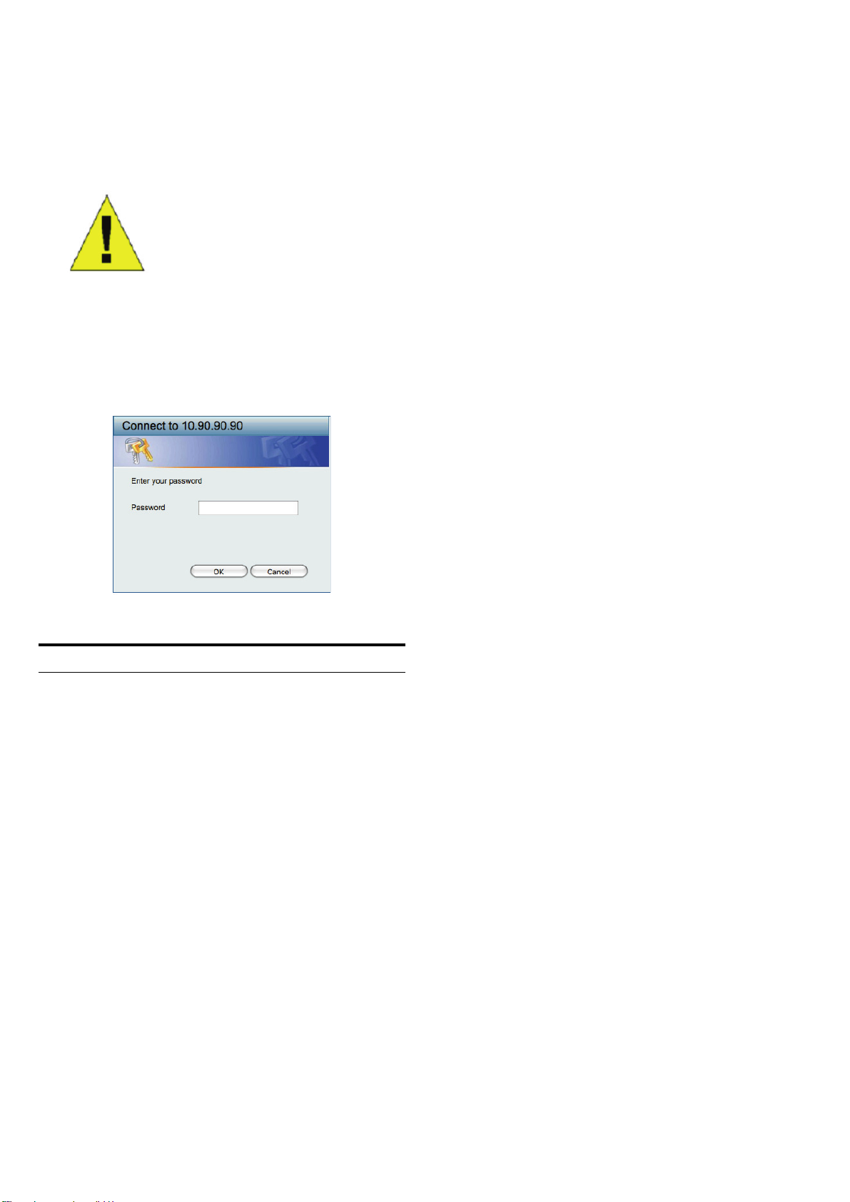
Step 3
When the following logon box appears, enter “admin” for
the password. Press OK to enter the main configuration
window.
Figure 8. User authentication window
1. Insert the Utility CD into your CD-Rom Drive.
2. From the Start
choose Run.
3. In the Run dialog box, type
D-link_SmartConsole_Utility.exe
the drive letter of your CD-Rom) and click OK.
4. Follow the on-screen instructions to install the utility.
5. Upon completion, go to
SmartConsole Utility and open the SmartConsole
Utility.
6. Just connect the EasySmart Switch to the same
L2 network segment of your PC and use the
SmartConsole Utility to discover the EasySmart
Switches.
For a detailed look at SmartConsole’s functions, please
refer to the SmartConsole Utility introduction in the user
manual.
menu on the Windows desktop,
G:\SmartConsole Utility\
(where G:\ represents
Start > Programs > D-Link
SmartConsole Utility
The SmartConsole Utility included on the installation CD
is a program for discovering EasySmart Switches with
the same L2 network segment connected to your PC.
This tool is only for computers running Windows 2000,
Windows XP, and Windows Vista x64/86 operating
systems. There are two options for the installation of
SmartConsole Utility, one is through the autorun program
on the installation CD and the other is manual installation.
Note: Please be sure to remove any existing SmartConsole
Utility from your PC before installing the latest SmartConsole
Utility.
Option 1: Follow these steps to install the SmartConsole
Utility via the autorun program on the installation CD.
1. Insert the Utility CD into your CD-Rom Drive.
2. The autorun program will pop up automatically
3. Simply click on the ”Install SmartConsole Utility”
button and an installation wizard will guide you
through the process.
4. After successfully installing the SmartConsole Utility,
you can open the utility by clicking Start > Programs
> D-Link SmartConsole Utility.
4
Page 5

5
Page 6
Über dieses Handbuch
Diese Kurzanleitung für die Installation hilft Ihnen Schritt
für Schritt bei der Inbetriebnahme aller EasySmart Switches
von D-Link. Bitte beachten Sie, dass das von Ihnen
erworbene Modell im äußeren Erscheinungsbild leicht von
den in den Illustrationen abgebildeten Modellen abweichen
kann.
Einzelheiten über Ihr Gerät, seine Komponenten, das
Einrichten von Netzwerkverbindungen sowie die technischen
Daten können Sie dem mitgelieferten Benutzerhandbuch
entnehmen.
Abbildung 1: Gummifüße anbringen
Rackmontage
Schritt 1 – Auspacken
Öffnen Sie die Transportverpackung, und entnehmen Sie
vorsichtig den Inhalt. Vergewissern Sie sich anhand der
Packliste im Benutzerhandbuch, dass alle Bestandteile
vollständig und unbeschädigt vorhanden sind. Sollte
eines der Teile fehlen oder beschädigt sein, wenden Sie
sich bitte an Ihren D-Link-Fachhändler.
- Ein D-Link EasySmart Switch
- Einbauwinkel
- Stromkabel
- CD-ROM mit Benutzerhandbuch und dem
Dienstprogramm SmartConsole
- Eine Kurzanleitung in mehreren Sprachen
- Ein Zubehörsatz für ein Schraubfundament
Schritt 2 – Switch installieren
Gehen Sie zum sicheren Installieren und Betreiben des
Switch wie folgt vor:
Der Switch kann in einem 11-Zoll-Rack (EIAStandardgröße) montiert und mit weiteren Geräten in
einem Verkabelungsschrank installiert werden. Bringen
Sie an jedem Seitenblech des Switch einen Einbauwinkel
an, und schrauben Sie die Winkel mit den beiliegenden
Schrauben fest.
Montieren Sie danach den Switch im Einschub mit den
Schrauben, die Sie zu Ihrem Rack erhalten haben.
Abbildung 2: Einbauwinkel anbringen
♦ Vergewissern Sie sich, dass das Stromkabel
unbeschädigt ist, und achten Sie auf den festen
Sitz der Steckverbindungen.
♦ Sorgen Sie für eine funktionierende Wärmeableitung
und eine ausreichende Belüftung in der Umgebung
des Switch.
♦ Stellen Sie keine schweren Gegenstände auf den
Switch.
Tisch- oder Regalmontage
Wenn Sie den Switch auf einem Tisch oder in einem
Regal aufstellen möchten, bringen Sie vorher die
mitgelieferten Gummifüße in den vier Ecken an der
Unterseite des Gehäuses an. Lassen Sie um das Gerät
herum genug Platz zur Belüftung frei.
Abbildung 3: Switch im Standardrack installieren
Switch Wandmontage
Der DGS-1100 Desktop-Switch kann auch an einer Wand
angebracht werden. Zu diesem Zwecke stehen zwei
Aussparungen zur waagerechten oder senkrechten
Aufhängung auf der Unterseite des Switches zur Verfügung.
Stellen Sie sicher, dass bei der Wandmontage die
Vorderseite des Geräts gut sichtbar ist, damit die LEDs
zu erkennen sind. Zur Veranschaulichung der Montage
sehen Sie sich bitte die Illustrationen unten an:
6
Page 7
A.) Montage an einer Mauer aus Backstein oder Beton
1. Bohren Sie im Mauerwerk Löcher 5x22mm und
setzen Sie die Plastikdübel ein.
2 Drehen Sie die Schrauben 3x15 in die Dübel nicht
ganz bis zum Anschlag ein.
3. Richten Sie die unten am Gerät befindlichen
Aussparungen über den Schrauben aus und hängen
Sie das Gerät ein.
B.) Montage an einer Wand aus Holz
1. Drehen Sie die zwei 3x15mm Schrauben in die
Holzwand ein.
2. Richten Sie die unten am Gerät befindlichen
Aussparungen über den Schrauben aus und hängen
Sie das Gerät ein.
Verwaltungsoptionen
Das Management des D-Link EasySmart Switch ist über
einen Webbrowser oder einen PC mithilfe der
SmartConsole-Hilfsanwendung möglich.
Soll lediglich ein D-Link EasySmart Switch verwaltet
werden, ist das webbasierte Management die bessere
Option. Jedem Switch muss eine eigene IP-Adresse
zugewiesen werden, die zur Kommunikation mit dem
webbasierten Management verwendet wird, und der PC
sollte eine IP-Adresse im gleichen Adressenbereich wie
der Switch haben.
Sollen jedoch mehrere D-Link EasySmart Switches
verwaltet werden, ist die SmartConsole-Hilfsanwendung
die bessere Option. Wenn Sie die SmartConsoleHilfsanwendung verwenden, müssen Sie die IP-Adresse
Ihres PC nicht ändern und es ist leicht, die Ersteinstellung
mehrerer EasySmart Switches zu starten. Nähere Angaben
finden Sie in den folgenden Installationsanleitungen für
das webbasierte Management und die SmartConsoleHilfsanwendung.
(1) Mindestens 20mm für eine Wand aus Holz.
(2) Mindestens 80mm für eine Mauer.
Abbildung 4. Desktop-Switch - Wandmontage
Schritt 3 – An die
Stromversorgung anschließen
Schließen Sie das Stromkabel an eine Steckdose
(möglichst geerdet und mit Überspannungsschutz) und
an den Netzanschluss auf der Rückseite des Switch an.
Die webbasierte Management-Benutzeroberfläche
Nach erfolgreicher Installation können Sie den Switch
konfigurieren, die LED-Anzeigen überwachen und Statistiken
grafisch über einen Webbrowser anzeigen lassen, z. B.
mit Netscape Navigator (Version 6.2 und höher) oder
Microsoft
Sie benötigen das folgende Zubehör, um mit der
Webkonfiguration Ihres Geräts zu beginnen:
Einen PC mit einem RJ-45-Ethernet-Anschluss
Ein Standard-Ethernetkabel
®
Internet Explorer (Version 5.0 und höher).
Schritt 1
Verbinden Sie das Ethernetkabel mit einem beliebigen
Anschluss auf der Vorderseite des Switch und mit dem
Ethernetanschluss an Ihrem PC.
Abbildung 5: Switch an die Stromversorgung anschließen
Stromausfall
Aus Sicherheitsgründen sollten Sie bei einem Stromausfall
den Netzstecker ziehen. Ist die Stromversorgung wieder
gewährleistet, können Sie den Netzstecker des Switch
wieder einstecken.
Abbildung 6: Ethernetkabel anschließen
7
Page 8
Schritt 2
SmartConsole
Zur Anmeldung und um den Switch über eine EthernetVerbindung zu konfigurieren, muss der PC eine IP-Adresse
im gleichen Adressenbereich wie der Switch aufweisen.
Beispiel: Wenn der Switch die IP-Adresse 10.90.90.90
hat, sollte der PC die IP-Adresse 10.x.y.z haben (wobei
x/y eine Zahl zwischen 0 ~ 254 und z eine zwischen 1 ~254
ist) und eine Subnetzmaske 255.0.0.0.
Öffnen Sie Ihren Webbrowser, und geben Sie
http://10.90.90.90 (die werkseitige Standard-IP-Adresse)
in die Adresszeile ein. Drücken Sie anschließend die
Eingabetaste.
Die Webkonfiguration kann auch über das
Dienstprogramm SmartConsole vorgenommen werden.
Öffnen Sie SmartConsole, und doppelklicken Sie in der
Geräteliste auf den Switch. Daraufhin wird die
Webkonfiguration automatisch in Ihrem Webbrowser
geladen.
Abbildung 7: IP-Adresse 10.90.90.90
in den Webbrowser eingeben
HINWEIS: Die werkseitige Standard-IP-
Adresse des Switch lautet 10.90.90.90,
die Subnetzmaske 255.0.0.0 und das
Standard-Gateway 0.0.0.0
Schritt 3
Wenn der folgende Anmeldedialog angezeigt wird,
geben Sie „admin“ als Kennwort ein. Klicken Sie
anschließend auf OK.
Abbildung 8: Benutzerauthentifizierung
Das Dienstprogramm SmartConsole befindet sich auf der
Installations-CD und ist ein Programm zur Suche von
EasySmart Switches mit dem gleichen L2-Netzwerksegment,
mit dem Ihr PC verbunden ist. Dieses Tool läuft nur auf
Computern mit dem Betriebssystem Windows 2000,
Windows XP oder Windows Vista x64/86. Sie können
SmartConsole auf zwei Arten installieren: über das
Installationsprogramm auf der Installations-CD oder manuell.
Hinweis: Falls auf Ihrem Computer bereits eine Version
von SmartConsole installiert ist, müssen Sie diese
deinstallieren, bevor Sie die neueste Version von
SmartConsole installieren können.
1. Option: Führen Sie die folgenden Schritte durch,
um SmartConsole über das auf der Installations-CD
vorhandene Installationsprogramm zu installieren.
1. Legen Sie die CD in das CD-ROM-Laufwerk ein.
2. Das Installationsprogramm wird automatisch geöffnet.
3.
Klicken Sie auf die Schaltfläche Install SmartConsole
Utility (SmartConsole installieren). Der daraufhin
angezeigte Installationsassistent wird Sie durch den
Installationsvorgang führen.
4. Nachdem Sie SmartConsole erfolgreich installiert
haben, können Sie das Dienstprogramm über Start
> Programs (Programme) > D-Link SmartConsole
Utility öffnen.
5. Schließen Sie den EasySmart Switches an das gleiche
L2-Netzwerksegment Ihres PC an, und führen Sie
mit SmartConsole eine Suche nach EasySmart
Switches durch.
2. Option: Führen Sie die folgenden Schritte durch,
um das Dienstprogramm SmartConsole manuell zu
installieren.
1. Legen Sie die CD in das CD-ROM-Laufwerk ein.
2. Klicken Sie unter Windows im Menü Start auf Run
(Ausführen).
3. Geben Sie im Dialogfeld Run (Ausführen) folgende
Befehlszeile ein: G:\SmartConsole Utility\
D-link_SmartConsole_Utility.exe (hierbei steht
„G:“ für den Laufwerksbuchstaben Ihres CD-ROMLaufwerks). Klicken Sie anschließend auf OK.
4. Befolgen Sie die Installationsanweisungen auf dem
Bildschirm.
5. Klicken Sie nach Abschluss der Installation zum Starten
des Dienstprogramms SmartConsole auf Start ->
Programs (Programme) -> SmartConsole Utility.
6. Schließen Sie den EasySmart Switches an das
gleiche L2-Netzwerksegment Ihres PC an, und
führen Sie mit SmartConsole eine Suche nach
EasySmart Switches durch.
Weitere Informationen zu den Funktionen von SmartConsole
finden Sie im Benutzerhandbuch in der Einführung zu
SmartConsole.
8
Page 9

9
Page 10
À propos de ce guide
Ce guide vous explique, étape par étape, comment
configurer tous les EasySmart Switches Web de D-Link.
Remarque : il se peut que votre modèle d’appareil diffère
légèrement de ceux illustrés dans le présent manuel.
Pour obtenir des informations plus détaillées sur votre
switch, ses composants, ses connexions réseau et ses
spécifications techniques, reportez-vous au Guide de
l’utilisateur fourni dans son emballage.
Étape 1 : déballage
Ouvrez le carton d’expédition et sortez-en le contenu
avec précaution. Le Guide de l’utilisateur contient une
liste des éléments devant se trouver dans l’emballage ;
en vous y reportant, vérifiez que tous les composants
sont présents et en parfait état. Si un élément est absent
ou détérioré, contactez votre revendeur D-Link pour en
obtenir un nouveau.
- Un EasySmart Switch Web D-Link
- Un support pour montage en armoire
- Un cordon d’alimentation
- Le CD du Guide de l’utilisateur, incluant l’utilitaire
SmartConsole
- Un guide de démarrage multilingue
- Un kit d’accessoire pour mise à la terre d’une vis
Pieds en caoutchouc
Figure 1. Fixation des pieds en caoutchouc
Installation dans une armoire
Vous pouvez monter votre switch dans une armoire
11 pouces EIA standard, à insérer dans une armoire de
câblage avec d’autres équipements. Pour cela, installez
les supports sur les panneaux latéraux du switch (un de
chaque côté) et fixez-les à l’aide des vis fournies.
Figure 2. Fixation des supports de montage
Utilisez ensuite les vis fournies pour monter le switch
dans l’armoire.
Étape 2 : installation du switch
Pour installer et utiliser le switch en toute sécurité, nous
vous recommandons de procéder comme suit :
♦ Inspectez le cordon d’alimentation et assurez-vous
qu’il est parfaitement relié au connecteur
d’alimentation secteur.
♦ Vérifiez que le switch présente une dissipation de
chaleur adaptée et qu’il est entouré d’un espace
suffisant pour garantir une bonne ventilation.
♦ Ne posez pas d’objets lourds sur le switch.
Installation sur un bureau ou sur une étagère
Pour installer le switch sur un bureau ou une étagère,
vous devez ajouter les pieds en caoutchouc fournis aux
quatre coins de sa base. À des fins de ventilation,
prévoyez un espace suffisant entre l’appareil et les
objets environnants.
Figure 3. Installation du switch dans une armoire de taille
standard
Installation du commutateur sur un mur
(montage mural)
Le commutateur DGS-1100 au format PC peut
également être installé sur un mur. À cet effet, deux
trous de fixation sont prévus sous le commutateur.
Veuillez vous assurer que le panneau avant soit bien en
vue afin que les voyants lumineux soient visibles.
Veuillez vous reporter aux illustrations ci-dessous :
10
Page 11
A.) Installation sur un mur en béton
1. Insérez les chevilles nylon dans le mur en béton.
2. Serrez les vis T3 x 15L dans les chevilles nylon.
3. Accrochez le commutateur sur les vis, les trous de
fixation se trouvant sur la partie inférieure du
périphérique. L'installation est maintenant terminée.
B.) Installation sur un mur en bois
1. Serrez les vis T3 x 15L dans le mur en bois.
2. Accrochez le commutateur sur les vis, les trous de
fixation se trouvant sur la partie inférieure du
périphérique. L'installation est maintenant terminée.
Panne de courant
En cas de panne de courant, par précaution, débranchez
le switch. Rebranchez-le une fois le courant rétabli.
Options d’administration
Le commutateur EasySmart de D-Link peut être géré par
le biais d’un navigateur Web ou via un PC utilisant l’utilitaire
SmartConsole.
Si vous ne voulez gérez qu’un seul commutateur
EasySmart de D-Link, l’option Web est préférable. Chaque
commutateur doit posséder sa propre adresse IP pour
communiquer avec le Web ; l'adresse IP du PC doit se
trouver sur la même plage que celle du commutateur.
Cependant, si vous voulez gérez plusieurs commutateurs
EasySmart de D-Link, l’utilitaire SmartConsole est une
meilleure option. En effet, il vous évite de devoir changer
l’adresse IP de votre PC et facilite la configuration initiale
de plusieurs commutateurs EasySmart. Reportez-vous aux
instructions d’installation détaillées suivantes concernant
la gestion Web et l’utilitaire SmartConsole.
(1) Minimum 19 mm pour un mur en bois.
(2) Minimum 7 cm pour un mur en
Figure4. Installation d'un commutateur au format
PC sur un mur
Étape 3 : raccordement au
secteur
À présent, reliez le switch à une prise de courant (de
préférence mise à la terre et dotée d’un parasurtenseur)
à l’aide du cordon d’alimentation secteur branché à
l’arrière du switch.
Interface de gestion Web
Une fois l’installation physique effectuée, vous pouvez
configurer le switch, surveiller les voyants et afficher des
graphiques de statistiques à l’aide d’un navigateur Web
(Netscape Navigator version 6.2 ou supérieure, ou
Microsoft® Internet Explorer version 5.0 ou supérieure,
par exemple).
Pour commencer la configuration Web de votre unité,
vous avez besoin des éléments suivants :
PC équipé d’une connexion Ethernet RJ-45
Câble Ethernet standard
Étape 1
Connectez une extrémité du câble Ethernet à l’un des
ports disponibles sur le panneau avant du switch et
l’autre extrémité au port Ethernet de l’ordinateur.
Figure 5. Raccordement du switch à une prise de courant
Figure 6. Branchement du câble Ethernet
11
Page 12
Étape 2
Utilitaire SmartConsole
Pour pouvoir ouvrir une session et configurer le commutateur
via une connexion Ethernet, l'adresse IP du PC doit être
dans la même plage que celle du commutateur. Par
exemple, si l'adresse IP du commutateur est 10.90.90.90,
l'adresse IP du PC doit être 10.x.y.z (où x et y sont
compris entre 0 et 254 et z est compris entre 1 et 254) et
son masque de sous-réseau doit être 255.0.0.0.
Ouvrez votre navigateur Web et, dans la barre d’adresse,
tapez http://10.90.90.90 (adresse IP par défaut). Ensuite,
appuyez sur <Entrée>.
Figure 7. Saisie de l’adresse IP 10.90.90.90
Vous pouvez également accéder à la configuration Web
via l’utilitaire SmartConsole. Ouvrez l’utilitaire
SmartConsole et, dans la liste des switches, doublecliquez sur celui de votre choix. La configuration Web est
automatiquement chargée dans votre navigateur Web.
dans le navigateur Web
REMARQUE : L’adresse IP par
défaut du switch est 10.90.90.90 ; son
masque de sous-réseau est 255.0.0.0
et sa passerelle par défaut, 0.0.0.0
Étape 3
Lorsque la boîte de connexion suivante apparaît, entrez
le mot de passe « admin ». Appuyez sur OK pour ouvrir
la fenêtre de configuration principale.
Figure 8. Fenêtre d’authentification utilisateur
L’utilitaire SmartConsole est inclus dans le CD
d’installation. Il s’agit d’un programme de détection des
EasySmart Switches connectés au même segment de
réseau de niveau 2 que le PC. Cet outil concerne
uniquement les PC exécutant Windows 2000, Windows
XP et Windows Vista x64/86. Vous pouvez procéder de
deux manières pour installer cet utilitaire : en lançant le
programme d’installation automatique présent sur le CD
ou manuellement.
Remarque : avant d’installer la dernière version de l’utilitaire
SmartConsole, veillez à supprimer toute installation
précédente.
Option 1 : la procédure suivante vous permet d’installer
l’utilitaire SmartConsole via le programme d’installation
automatique du CD.
1. Insérez le CD de l’utilitaire dans le lecteur de CD-ROM.
2. Le programme d’installation automatique apparaît.
3.
Cliquez sur le bouton “Install SmartConsole Utility”
(Installer l’utilitaire SmartConsole). Un assistant vous
guidera tout au long du processus.
4. Une fois l’utilitaire installé, ouvrez-le en cliquant sur
Démarrer > Tous les programmes > D-Link
SmartConsole Utility (Utilitaire D-Link SmartConsole).
5. Connectez le EasySmart Switch au même segment
de réseau de niveau 2 que le PC et détectez les
Smart Switches présents via l’utilitaire SmartConsole.
Option 2 : la procédure suivante vous permet d’installer
l’utilitaire SmartConsole manuellement.
1. Insérez le CD de l’utilitaire dans le lecteur de CD-ROM.
2. Dans le menu Démarrer du bureau Windows,
3. Dans la boîte de dialogue Exécuter, tapez
4. Pour installer l’utilitaire, suivez les instructions
5. Une fois l’installation terminée, sélectionnez Démarrer
6. Connectez le EasySmart Switch au même segment
Pour une présentation détaillée des fonctions de
l’utilitaire SmartConsole, consultez la présentation qui lui
est consacrée dans le Guide de l’utilisateur.
choisissez Exécuter
G:\SmartConsole Utility\
D-link_SmartConsole_Utility.exe (où G:\ correspond
à votre lecteur de CD-ROM), puis cliquez sur OK.
affichées à l’écran.
> Tous les programmes > D-Link SmartConsole
Utility (Utilitaire D-Link SmartConsole), puis
lancez l’utilitaire SmartConsole
de réseau de niveau 2 que le PC et détectez les
EasySmart Switches présents via l’utilitaire
SmartConsole.
.
.
12
Page 13

13
Page 14
Sobre esta guía
Esta guía ofrece las instrucciones detalladas para
configurar todos los switches EasySmart de D-Link.
Tenga en cuenta que el modelo que ha comprado puede
ser algo diferente al que se muestra en las ilustraciones.
Si desea más información sobre el switch, sus
componentes, la manera de realizar las conexiones de
red o las especificaciones técnicas, consulte la Guía del
usuario que se incluye con el switch.
Figura 1. Fijar los pies de goma
Paso 1. Desempaquetar
Abra la caja y con cuidado saque el contenido. Consulte
la lista de componentes en la Guía del usuario para
asegurarse de que están todos los elementos y que se
encuentran en perfecto estado. Si falta algún
componente o ha sufrido algún daño, contacte con su
distribuidor de D-Link para que se lo cambie.
- Un switch EasySmart de D-Link.
- Ángulo para montaje en rack.
- Cable de alimentación
- CD con la Guía del usuario y el programa
SmartConsole.
- Una Guía de iniciación multilingüe.
- Un kit de accesorios para un tornillo con toma de tierra
Paso 2. Instalación del switch
Para que la instalación y el funcionamiento del switch
sean seguros, se recomienda que:
Instalación en rack
El switch se puede montar en un rack EIA estándar de
11'', que se puede colocar en un armario de cableado
junto a otros equipos. Para instalarlo, fije los ángulos de
montaje en los laterales del switch (uno a cada lado)con
los tornillos suministrados.
Figura 2. Fijar los ángulos de montaje
Luego, con los tornillos suministrados con el rack, monte
el switch en el rack.
♦ Inspeccione visualmente el cable de alimentación
para comprobar que está correctamente conectado
al conector de alimentación AC.
♦ Se asegure de que, alrededor del switch, el calor
se disipa correctamente y se ventila adecuadamente.
♦ No sitúa objetos pesados sobre el switch.
Instalación de sobremesa o en estante
Para instalar el switch sobre una mesa o en un estante,
debe fijar los pies de goma que se incluyen con el
dispositivo en la base del mismo, uno en cada esquina.
Deje suficiente espacio entre el dispositivo y los objetos
que haya alrededor para la ventilación.
Figura 3. Instalar el switch en un rack estándar
Montaje del conmutador en la pared
(montaje de pared)
El conmutador DGS-1100 de tamaño de escritorio se
puede montar también en la pared. Para este fin, en la
parte inferior del conmutador existen dos bahías de
montaje. Asegúrese de que el panel frontal está a la
vista para poder ver los LED. Consulte las ilustraciones
siguientes:
14
Page 15
A.) Montaje en una pared de hormigón
1. Fije los anclajes de nylon para tornillo en la pared de
hormigón.
2. Introduzca los tornillos T3 x 15L en los anclajes de
nylon para tornillo.
Corte del suministro eléctrico
Como precaución, en caso de corte del suministro eléctrico,
el switch debería desenchufarse. Cuando se restablece
el consumo eléctrico, puede volver a enchufarlo.
3. Enganche el conmutador que tiene los orificios de
montaje en la parte inferior en los tornillos y habrá
terminado.
B.) Montaje en una pared de madera
1. Introduzca los tornillos T3 x 15 L en la pared de madera.
2. Enganche el conmutador que tiene los orificios de
montaje en la parte inferior en los tornillos y habrá
terminado.
(1) Mínimo 3/4 de pulgada para pared de madera.
(2) Mínimo 3 pulgadas para pared de
Figura 4. Montaje de un conmutador de
escritorio en la pared
Opciones de gestión
El conmutador EasySmart D-Link se puede gestionar a
través de un explorador de web o de cualquier PC que
use la utilidad SmartConsole.
Si sólo desea gestionar un conmutador EasySmart DLink, la gestión basada en la web es la mejor opción. Se
debe asignar a cada conmutador su propia dirección IP,
que se utiliza para la comunicación con la gestión
basada en la web, y el PC debe tener una dirección IP
que esté en el mismo rango que el conmutador.
Sin embargo, si desea gestionar varios conmutadores
EasySmart D-Link, la utilidad SmartConsole es la mejor
opción. Al usar la utilidad SmartConsole, no es necesario
cambiar la dirección IP de su PC y resulta fácil iniciar la
configuración inicial de varios conmutadores EasySmart.
Consulte las instrucciones de instalación detalladas que
se muestran a continuación para la gestión basada en la
web y para la utilidad SmartConsole.
z de gestión basada en web
Tras haber realizado la instalación física sin problemas,
puede configurar el switch, controlar el panel de indicadores
LED y visualizar las estadísticas gráficamente por medio
de un navegador web, como Netscape Navigator
(versión 6.2 o superior) o Microsoft
(versión 5.0 o superior).
®
Internet Explorer
Paso 3. Conexión del cable de
alimentación AC
Ahora puede conectar el cable de alimentación AC a la
parte posterior del switch y a una toma eléctrica
(preferiblemente una que disponga de toma de tierra y
protector de sobretensión).
Figura 5. Conectar el switch a una toma eléctrica
Para realizar la configuración web del dispositivo, necesita
el equipo siguiente:
Un PC con una conexión Ethernet RJ-45.
Un cable Ethernet estándar.
Paso 1
Conecte el cable Ethernet a cualquiera de los puertos
del panel delantero del switch y al puerto Ethernet del
PC.
Figura 6. Conectar el cable Ethernet
15
Page 16

Paso 2
Utilidad SmartConsole
Para iniciar sesión y configurar el switch a través de una
conexión Ethernet, el PC debe tener una dirección IP en
el mismo rango que el switch. Por ejemplo, si el switch
tiene una dirección IP de 10.90.90.90, el PC debe tener
una dirección IP de 10.x.y.z (donde x/y es un número
entre 0 y 254 y z es un número entre 1 y 254), y una
máscara de subred de 255.0.0.0.
Abra el navegador web y escriba http://10.90.90.90 (la
dirección IP por defecto) en el campo de direcciones.
Luego pulse <Intro>.
Figura 7. Introducir la dirección IP 10.90.90.90
en el navegador web
A la configuración web también se puede acceder a
través de la utilidad SmartConsole. Abra la utilidad
SmartConsole y haga doble clic sobre el switch, que
figura en la lista de dispositivos. De este modo, se
cargará la configuración web en el navegador web.
NOTA: La dirección IP por
defecto del switch es
10.90.90.90, con una máscara
de subred de 255.0.0.0 y un
gateway por defecto de 0.0.0.0
Paso 3
Cuando aparezca la siguiente caja de entrada al sistema,
escriba «admin» en el campo contraseña. Pulse OK
para entrar en la ventana principal de configuración.
Figura 8. Ventana de autentificación del usuario
La utilidad SmartConsole incluida en el CD de instalación es
un programa para detectar switches con el mismo
segmento de red L2 conectados a su PC. Esta
herramienta es solo para ordenadores con los sistemas
operativos Windows 2000, Windows XP, y Windows
Vista x64/86. Para la instalación de la utilidad
SmartConsole se dispone de dos opciones: a través del
programa autorun del CD de instalación, o bien del
manual de instalación.
Nota: Asegúrese de que ha eliminado cualquier utilidad
SmartConsole que pudiera haber en su PC antes de
instalar la última versión de la utilidad SmartConsole.
Opción 1: Siga estos pasos para instalar la utilidad
SmartConsole a través del programa autorun del CD
de instalación.
1. Introduzca el CD de la utilidad en la unidad de CD-ROM.
2. El programa autorun se abrirá automáticamente.
3. Haga clic en el botón «Instalar utilidad SmartConsole»
y un asistente de instalación lo guiará a lo largo del
proceso.
4. Tras haber instalado correctamente la utilidad
SmartConsole, abra la utilidad haciendo clic en
Inicio > Programas > D-Link SmartConsole Utility.
5. Conecte el EasySmart Switch al mismo segmento de
red L2 de su PC y use la utilidad SmartConsole
para detectar los switches EasySmart.
Opción 2: Siga estos pasos para instalar la utilidad
SmartConsole manualmente.
1. Introduzca el CD de la utilidad en la unidad de CD-ROM.
2. En el menú Inicio
Ejecutar.
3. En el cuadro de diálogo Ejecutar, escriba «
G:\SmartConsole Utility\
D-link_SmartConsole_Utility.exe» (donde G:\
representa la letra de la unidad de su CD-ROM) y
haga clic en OK.
4. Siga las instrucciones que aparecen en la pantalla
para instalar la utilidad.
5. Tras completarlo, vaya a
D-Link SmartConsole Utility y abra la utilidad
SmartConsole.
6. Conecte el switch EasySmart Switch al mismo
segmento de red L2 de su PC y use la utilidad
SmartConsole para detectar los switches EasySmart.
Si desea más información sobre las funciones de la
utilidad SmartConsole, consulte la introducción a la
utilidad SmartConsole en el Manual del usuario.
del escritorio de Windows, elija
Inicio > Programas >
16
Page 17

17
Page 18

Informazioni sul presente
manuale
Il presente manuale rapido d’installazione fornisce le
istruzioni per impostare tutti i EasySmart Switch di D-Link.
Il modello acquistato potrebbe differire leggermente da
quello riportato nelle illustrazioni.
Maggiori informazioni sullo switch, i suoi componenti, le
connessioni di rete e le specifiche tecniche sono contenute
nel Manuale utente fornito con il prodotto.
Figura 1. Fissaggio dei piedini in gomma
Fase 1 – Disimballaggio
Aprire la confezione ed estrarne delicatamente il contenuto.
Verificare il contenuto del pacchetto, confrontandolo con
l’elenco riportato nel manuale utente. Se un componente
dovesse risultare mancante o danneggiato, contattare il
rivenditore D-Link locale per la sostituzione.
- 1 EasySmart Switch D-Link
- Staffe per montaggio su rack
- Cavo di alimentazione
- CD del Manuale utente con programma SmartConsole
Utility
- 1 manuale rapido di installazione multilingue
- Un kit di accessori per una vite di terra
Fase 2 – Installazione dello
Installazione su rack
Lo switch può essere montato in un rack da 11 pollici,
conforme allo standard EIA, posizionabile in un armadio
elettrico. Fissare le staffe di montaggio ai pannelli laterali
dello switch (una per lato) e fermarle con le viti fornite.
Figura 2. Fissaggio delle staffe di montaggio
Montare lo switch all’interno del rack, utilizzando le viti
fornite con quest’ultimo.
switch
Per una installazione sicura dello switch, si consiglia di:
♦ Ispezionare il cavo di alimentazione e verificare
che sia correttamente fissato al relativo connettore
CA.
♦ Verificare che attorno allo switch ci sia lo spazio
sufficiente per un’adeguata ventilazione e
dissipazione del calore.
♦ Non posizionare oggetti pesanti sopra lo switch.
Installazione su un ripiano o una scrivania
Per installare lo switch su un ripiano o una scrivania,
fissare i piedini in gomma forniti con il dispositivo ai
quattro angoli del pannello inferiore. Per consentire una
corretta ventilazione è necessario lasciare uno spazio
sufficiente tra il dispositivo e gli oggetti circostanti.
Figura 3. Installazione dello switch all’interno del rack
Montaggio dello switch a parete
Lo switch DGS-1100 da scrivania può essere anche
montato a parete. A tale scopo è possibile utilizzare le
apposite scanalature presenti nella parte inferiore dello
switch. Per il montaggio assicurarsi di sistemare il pannello
frontale in modo da consentire la visualizzazione dei LED.
Fare riferimento alle figure seguenti:
18
Page 19

A.) Montaggio su parete in cemento
1. Praticare dei fori nella parete in cemento e inserirvi i
tasselli in nylon.
2. Avvitare le viti T3 x 15 L nei tasselli in nylon.
3. Agganciare lo switch facendo in modo che le viti risultino
inserite nelle scanalature.
B.) Montaggio su parete in legno
1. Avvitare le viti T3 x 15 L nella parete in legno.
2. Agganciare lo switch facendo in modo che le viti risultino
inserite nelle scanalature.
(1) Almeno 2 cm per la parete in legno.
(2) Almeno 7,5 cm per la parete in.
Figura 4. Montaggio a parete di uno switch da scrivania
Fase 3 – Collegamento del cavo
di alimentazione CA
Opzioni di gestione
È possibile gestire il dispositivo D-Link EasySmart Switch
da un browser Web o da qualsiasi PC tramite SmartConsole
Utility.
Se si desidera gestire un solo dispositivo D-Link
EasySmart Switch, è preferibile utilizzare la funzione
Gestione basata sul Web. È necessario assegnare a
ogni switch un indirizzo IP, che verrà utilizzato per
comunicare con Gestione basata sul Web. È inoltre
necessario che al PC sia assegnato un indirizzo IP
compreso nello stesso intervallo di quello dello switch.
Se tuttavia si desidera gestire più dispositivi D-Link
EasySmart Switch, è preferibile utilizzare la funzione
SmartConsole Utility. Con SmartConsole Utility non è
necessario modificare l'indirizzo IP del PC ed è possibile
avviare l'installazione di più dispositivi EasySmart Switch.
Per le funzioni Gestione basata sul Web e SmartConsole
Utility, fare riferimento alle istruzioni di installazione
dettagliate riportate di seguito.
Interfaccia di gestione basata sul Web
Al termine dell’installazione fisica, è possibile configurare
lo switch, monitorare il pannello dei LED e visualizzare
graficamente le statistiche utilizzando un browser come
Netscape Navigator (versione 6.2 o superiore) o
Microsoft
Requisiti necessari per la configurazione del dispositivo:
PC dotato di connessione Ethernet RJ-45
Cavo Ethernet standard
®
Internet Explorer (versione 5.0 o superiore).
È ora possibile connettere il cavo di alimentazione CA al
relativo connettore posto sul pannello posteriore dello
switch e a una presa di corrente (preferibilmente dotata
di messa a terra e protezione da sovratensioni).
Figura 5. Collegamento dello switch alla presa di corrente
Interruzione di corrente
Per precauzione, in caso di un’interruzione di corrente si
consiglia di disconnettere lo switch. Riconnettere il
dispositivo quando l’erogazione di corrente elettrica torna
alla normalità.
Fase 1:
Collegare il cavo Ethernet a una delle porte poste sul
pannello frontale dello switch e a una porta Ethernet del
PC.
Figura 6. Connessione del cavo Ethernet
19
Page 20

Fase 2:
SmartConsole Utility
Per poter effettuare l'accesso e configurare lo switch
tramite una connessione Ethernet, gli indirizzi IP del PC
e dello switch devono essere compresi nello stesso
intervallo. Ad esempio, se l'indirizzo IP dello switch è
10.90.90.90, l'indirizzo IP del PC deve essere 10.x.y.z
(dove x/y è un numero compreso tra 0 e 254 e z è un
numero compreso tra 1 e 254), mentre la subnet mask
deve essere 255.0.0.0.
Aprire il browser web e inserire http://10.90.90.90
(indirizzo IP di default) nel campo indirizzo. Premere
<Invio>.
Figure 7. Inserire l'indirizzo IP 10.90.90.90 nel browser
Anche la SmartConsole Utility consente di accedere
alla procedura di configurazione attraverso il web.
Aprire la SmartConsole Utility e fare doppio clic sullo
switch presente nell'Elenco dispositivi. La procedura di
configurazione viene automaticamente caricata nel
browser web.
NOTA: L’indirizzo IP di default
dello switch è 10.90.90.90 con
subnet mask 255.0.0.0 e
gateway di default 0.0.0.0
Fase 3:
Quando appare la finestra di login illustrata di seguito,
inserire “admin” nel campo password. Premere OK per
accedere alla finestra principale della procedura di
configurazione.
Figura 8. Finestra di autenticazione dell'utente
La SmartConsole Utility inclusa nel CD di installazione è
un programma che consente di individuare gli EasySmart
Switch appartenenti al segmento di rete L2 connesso al
PC. Questo strumento può essere utilizzato esclusivamente
con computer dotati di sistema operativo Windows 2000,
Windows XP o Windows Vista x64/86. Per l'installazione
della SmartConsole Utility sono disponibili due opzioni:
installazione mediante programma autorun sul CD di
installazione o installazione manuale.
Nota: Rimuovere tutte le SmartConsole Utility presenti
sul PC prima di installare l'ultima versione del programma.
Opzione 1: per installare la SmartConsole Utility,
utilizzando il programma autorun presente sul CD di
installazione, eseguire i passi descritti di seguito.
1. Inserire il CD dell'Utility nella relativa unità.
2. Il programma viene caricato automaticamente.
3. Cliccare sul pulsante ”Installa la SmartConsole
Utility” per avviare la procedura di installazione.
4. Al termine dell'installazione della SmartConsole Utility, è
possibile aprire il programma cliccando su Start >
Programmi > D-Link SmartConsole Utility.
5. Connettere lo EasySmart Switch allo stesso segmento
di rete L2 del PC e utilizzare la SmartConsole
Utility per individuare il dispositivo.
Opzione 2: per installare manualmente la SmartConsole
eseguire i seguenti passi.
1. Inserire il CD dell'Utility nella relativa unità.
2. Dal menu Start
Esegui.
3. Nella finestra di dialogo Esegui, digitare
G:\SmartConsole Utility\
D-link_SmartConsole_Utility.exe (G:\ è la lettera
che rappresenta l'unità CD-Rom) e cliccare su OK.
4. Seguire le istruzioni visualizzate per installare l'utility.
5. Al termine del processo, selezionare
Programmi > D-Link SmartConsole Utility per
aprire il programma.
6. Connettere lo EasySmart Switch allo stesso segmento
di rete L2 del PC e utilizzare la SmartConsole
Utility per individuare il dispositivo.
Il capitolo Introduzione alla SmartConsole Utility del manuale
utente contiene una panoramica dettagliata delle funzioni
disponibili.
del desktop di Windows, selezionare
Start >
20
Page 21

21
Page 22

Введение
Данное руководство содержит пошаговые инструкции
для настройки всех коммутаторов серии D-Link EasySmart.
Пожалуйста, имейте в виду, что приобретенная модель
может незначительно отличаться от изображенной на
иллюстрациях. За более подробной информацией о
коммутаторе, его компонентах, подключении к сети и
технической спецификацией, пожалуйста, обратитесь
к руководству пользователя, включенного в комплект
поставки коммутатора.
Шаг 1 – Распаковка
Рисунок 1. Крепление резиновых ножек
Установка в стойку
Откройте коробку и аккуратно достаньте ее
содержимое. Пожалуйста, сверьтесь со списком
комплекта поставки, расположенным в руководстве
пользователя. Если какой-то из этих элементов
отсутствует или поврежден, пожалуйста, обратитесь
к продавцу для замены.
- Один коммутатор D-Link EasySmart
- Кронштейны для монтажа в стойку
- Шнур питания
- Компакт-диск с руководством пользователя и
утилитой SmartConsole
-
Одно мультиязычное руководство по быстрой установке
- Комплект для заземления
Шаг 2 – Установка коммутатора
Для безопасной работы и установки коммутатора
необходимо сделать следующие шаги:
♦ Визуально проверьте силовой кабель и
убедитесь в безопасности его подключения к
разъему питания переменного тока
Коммутатор допускает установку в 11-дюймовую
стойку EIA , которая, как правило, размещается в
серверной комнате вместе с другим оборудованием.
Прикрепите монтажные уголки к боковым панелям
коммутатора (по одному с каждой стороны) и
закрепите их прилагаемыми винтами.
Рисунок 2. Крепление монтажных уголков
Затем, используя винты от стойки, закрепите на ней
коммутатор.
♦ Убедитесь, что вокруг коммутатора достаточно
пространства для вентиляции
♦ Не размещайте тяжелые или нагревающиеся
объекты на коммутаторе
Установка на стол или поверхность
При установке коммутатора на стол или какую-нибудь
поверхность, необходимо прикрепить к нему
поставляемые вместе с ним резиновые ножки.
Самоклеющиеся ножки крепятся на дне устройства
по его углам. Обеспечьте достаточное пространство
для вентиляции между устройством и объектами
вокруг него.
Рисунок 3. Установка коммутатора в
стандартную стойку
Крепление коммутатора к стене
Коммутатор DGS-1100 настольного размера также
может быть прикреплен к стене. Для этой цели на
нижней части коммутатора предусмотрены два
разъема крепления. Пожалуйста, убедитесь в том,
что передняя панель расположена таким образом,
что видны индикаторы. Пожалуйста, обратитесь к
расположенным ниже иллюстрациям:
22
Page 23

A.) Крепление к бетонной стене
1. Закрепите нейлоновые дюбели в бетонной стене.
2. Вкрутите шурупы T3 x 15L в нейлоновые дюбели.
3. Повесьте коммутатор крепежными отверстиями
нижней части на шурупы; монтаж завершен.
B.) Крепление к деревянной стене
1. Вкрутите шурупы T3 x 15L в деревянную стену.
2. Повесьте коммутатор крепежными отверстиями
нижней части на шурупы; монтаж завершен.
(1) 3/4 дюйма - минимум для деревянной стены.
(2) 3 дюйма - минимум для бетонной стены.
Рисунок 4. Крепление настольного
коммутатора к стене
Шаг 3 – Подключение кабеля
питания переменного тока
На данном шаге подключите кабель питания к розетке
сети питания (желательно заземленной и защищенной
от перепадов напряжения).
Шаг 3 – Подключение кабеля
питания переменного тока
На данном шаге подключите кабель питания к
розетке сети питания (желательно заземленной и
защищенной от перепадов напряжения).
Сбой питания
В случае сбоя питания коммутатор должен быть
отключен. При восстановлении питания включите его
снова.
Функции управления
Управление коммутатором D-Link серии EasySmart
осуществляется через web-браузер или через любой
компьютер с помощью утилиты SmartConsole.
Если пользователю требуется управление только одним
коммутатором D-Link серии EasySmart, следует выбрать
управление на основе web-интерфейса. Каждому
коммутатору должен быть назначен собственный
IP-адрес, который используется для доступа к webинтерфейсу управления, компьютер должен обладать
IP-адресом в той же сети, что и коммутатор.
Тем не менее, для управления несколькими
коммутаторами D-Link серии EasySmart следует
использовать утилиту SmartConsole. Использование
утилиты SmartConsole исключает необходимость
изменять IP-адрес компьютера и обеспечивает легкую
начальную установку коммутаторов EasySmart.
Пожалуйста, обратитесь к подробным инструкциям по
установке для управления через web-интерфейс и
утилиту SmartConsole.
Управление на основе Web-интерфейса
После успешной установки можно начать настройку
коммутатора, следить за индикаторами на панели, и
отображать графическую статистику с помощью Web
-браузера, такого как Netscape Navigator (версии 6.2 и
выше) или Microsoft
®
Internet Explorer (версии 5.0 и выше).
Для Web-настройки устройства необходимо следующее
оборудование:
• Компьютер с разъемом RJ-45 для Ethernet-соединения
• Стандартный кабель Ethernet
Шаг 1
Подключите кабель Ethernet к любому порту на
передней панели коммутатора и к порту Ethernet на
компьютере.
Рисунок 5. Подключение коммутатора к розетке
Рисунок 6. Подключение Ethernet-кабеля
23
Page 24

Шаг 2
Утилита SmartConsole
Чтобы зарегистрироваться и настроить коммутатор
через Ethernet-соединение, необходимо назначить
компьютеру IP-адрес из того же диапазона, что и IPадрес коммутатора. Например, если коммутатору
присвоен IP-адрес 10.90.90.90, то компьютеру
необходимо присвоить IP-адрес вида 10.x.y.z (где x/y
– числа от 0 до 254, а z – число от 1 до 254) и маску
подсети 255.0.0.0.
Рисунок 7. Введите IP-адрес 10.90.90.90
в адресной строке Web-браузера
К Web-настройке также можно получить доступ с
помощью утилиты SmartConsole Utility. Запустите
утилиту SmartConsole Utility и дважды нажмите на
нужный коммутатор из списка устройств. Это
автоматически загрузит Web-конфигуратор в Webбраузере.
ПРИМЕЧАНИЕ: На
коммутаторах по умолчанию
используется IP-адрес
10.90.90.90 с маской подсети -
255.0.0.0 и шлюзом по
умолчанию - 0.0.0.0
Шаг 3
После того как появится окно регистрации, введите
“admin” в поле пароля. Нажмите OK для входа в
главное окно конфигурации.
Рисунок 8. Окно аутентификации пользователя
Утилита SmartConsole, включенная в установочный
компакт-диск, является программой для обнаружения
Smart-коммутаторов в одном сетевом сегменте 2
уровня, подключенных к компьютеру. Данную утилиту
можно установить только на компьютеры под
управлением следующих операционных систем:
Windows 2000, Windows XP и Windows Vista x64/86.
Имеется два варианта установки утилиты SmartConsole,
первый – через программу автозапуска на установочном
компакт-диске и другой – установка вручную.
Примечание: Перед установкой последней версии
SmartConsole, пожалуйста, убедитесь в том, что
любая старая версия утилиты SmartConsole
удалена из компьютера.
Вариант 1: Следуйте за этими шагами по установке
утилиты SmartConsole через программу автозагрузки
на установочном компакт-диске.
1. Поместите компакт-диск с утилитой в привод CD-ROM.
2. Программа автозагрузки откроется автоматически
3. Нажмите на кнопку ”Install SmartConsole Utility”
(Установить
утилиту SmartConsole) и мастер
установки проведет через процесс установки.
4. После окончания установки утилиты SmartConsole
можно запустить ее, нажав на Пуск > Программы >
D-Link SmartConsole Utility.
5. Подключите коммутатор серии EasySmart к тому
же самому сетевому сегменту 2 уровня, что и
компьютер и используйте утилиту SmartConsole
для обнаружения коммутаторов EasySmart.
Вариант 2: Следуйте этим шагам по установке
утилиты SmartConsole вручную.
1. Поместите
компакт-диск с утилитой в привод
CD-ROM.
2. Из меню Пуск
на рабочем столе Windows,
выберите Выполнить.
3. В диалоговом окне Запуск программы, введите
G:\SmartConsole Utility\
D-link_SmartConsole_Utility.exe (где G:\ - буква
привода CD-ROM) и нажмите OK.
4. Следуйте инструкциям на экране для установки
утилиты.
5. После завершения установки, нажмите Пуск >
Программы > D-Link SmartConsole Utility и
запустите утилиту SmartConsole.
6. Подключите коммутатор Smart к тому же
сетевому сегменту 2 уровня, что и компьютер,
затем используйте утилиту SmartConsole для
обнаружения коммутаторов Smart.
За детальной информацией по функциям утилиты
SmartConsole, пожалуйста, обратитесь к описанию
утилиты SmartConsole в руководстве пользователя.
24
Page 25

25
Page 26

關於本指南
機架安裝
本指南提供設定 D-Link 智慧型交換器的的說明,請注意
您購買的產品可能與下列說明有些許差異。
更多關於您的交換器細節資訊、配件、設定網連接路與技
術規格,請參閱產品包裝中的使用手冊。
步驟
小心打開包裝後,請參閱包裝內容物資料,確認所有品項
數量正確以及均正常沒有損壞,假如有任何品項遺失或損
壞,請聯絡當地的零售商更換。
- D-Link Web 智慧型交換器。
- 機架固定架。
- 電源線。
- 使用手冊光碟片(包含 SmartConsole Utility program)。
- 多國語言版設定指南。
- 一個附件包配一個接地螺絲。
1 –
打開包裝
交換器可以安裝在 EIA 標準尺寸的 11 吋機架,安裝時,
請將利用螺絲將機架固定架固定鎖緊在交換器的側面(兩
邊均要安裝)。
圖 2. 固定機架固定架
然後,使用包裝內所提供的螺絲,將交換器鎖到機架上面。
步驟
為了讓交換器安裝與運作安全,建議您以下幾件事情:
♦ 檢查電源線的外表,並確認 AC 電源連接插頭是安
♦ 請確認交換器周圍為適當的通風散熱環境。
♦ 不要放重物在交換器上。
2 –
全的。
交換器安裝
桌上型或架上行安裝
當安裝交換器在桌上或架子上,產品包裝內的橡膠腳墊請
安裝至交換器底部的四個角落,讓交換器與桌面有適當的
通風空間。
圖 1. 安裝橡膠腳墊
圖 3. 安裝交換器到標準尺寸的機架
將交換器安裝於牆上(壁掛)
若您需要將 DGS-1100 交換器安裝於牆上,在交換器的底
部具備 2 個璧掛插槽,可滿足您的需求。安裝前請確認安
裝交換器的位置與牆面有保留足夠的空間,讓您能確認前
方面板 LED 指示燈的燈號及狀態。請參考下列圖示及說
明:
A.) 璧掛於水泥牆上
1. 在水泥牆壁鑽孔後,將塑膠壁虎安裝於鑽孔處。
2. 將 T3 x 15L 螺絲釘旋入塑膠壁虎內。
3. 將交換器底部卡榫對準牆上螺絲釘,確認交換器穩固
後,完成璧掛。
B.) 璧掛於木牆上
1. 將 T3 x 15L 螺絲釘旋入木牆內。
2. 將交換器底部卡榫對準牆上螺絲釘,確認交換器穩固
後,完成璧掛。
26
Page 27

Utility,您不需更換您電腦的 IP 位址,即可輕鬆開始進行
多部智慧型交換器的初始設定,請參考接下來 Web-
Based Management 與 SmartConsole Utility 的詳細安裝
說明。
Web-based 管理介面
(1) 木牆至少要有 3/4 英吋厚
(2) 水泥牆至少要有 3 英吋厚
圖 4. 將交換器安裝於牆上(壁掛)
步驟
您可以連接 AC 電源線至交換器後方的的電源插孔(電源
插孔最好具備接地或高壓保護機制)
3 –
將
AC
電源線連接至交換器
設備成功安裝後,您可以設定交換器、監控LED面板顯示
與使用Netscape Navigator (6.2或以後版本)或Microsoft
Internet Explorer(5.0或以後版本)進行圖形化統計資料
顯示。
開始 Web 設定您的交換器時,您需要以下的設備:
電腦具備提供 RJ-45 介面乙太網路卡。
標準乙太網路線。
步驟
1
使用標準網路線連接電腦網路卡與交換器前方任何網路埠。
圖 6. 連接乙太網路線
®
圖 5. 將交換器電源插上牆壁插座
電源中斷
為了預防危險,如果發生電源中斷, 請立即拔掉插座,當
電源回覆,請將電源插上。
管理設定
D-Link 智慧型交換器可以使用網路瀏覽器管理,或可以透
過任何電腦用 SmartConsole Uititlity 進行管理。
假如您想要管理一部 D-Link 智慧型交換器,Web-based
Management 將會是較好的選擇,每部交換器會取得自己
的 IP 位址,可以讓 Web-Based Management 或電腦在相
同的 IP 網段進行通訊溝通之用。
不過,假如您要管理多部的 D-Link 智慧型交換器,
SmartConsole Utility 則是較好的選擇。使用 SmartConsole
步驟
2
電腦必須取得與交換器相同網段的 IP 位址,始可透過乙太
網路線連結登入與設定交換器,舉例來說,假如交換器的
IP 位址為 10.90.90.90,電腦的 IP 位址必須為 10.x.y.z (其中
x/y 需介於 0 ~ 254 之間,z 需介於 1 ~ 254 之間)
圖 7. 在瀏覽器輸入 IP 位址 10.90.90.90
網頁設定也可以透過 SmartConsole Utility 開啟,打開
SmartConsole Utility 當出現設備列表時,雙擊該交換器,
將會自動下載設定至您的瀏覽器中。
注意:交換器的 IP 位址原廠設定
值為 10.90.90.90、子網路遮罩為
255.0.0.0 與預設閘道為 0.0.0.0。
27
Page 28

步驟
3
當下面的登入視窗顯示,請在密碼欄輸入輸入“admin”,
接著按下 OK 至設定主視窗畫面。
圖 8. 使用者認證視窗
SmartConsole Utility
產品提供 SmartConsole Utility 程式,可以利用它經由電
腦搜尋與該電腦相同 L2 網段的交換器,這個工具僅支援
使用 Windows 2000、XP 與 Vista x64/86 作業系統的電腦,
安裝 SmartConsole Utility 有兩種方式,一是透過安裝光
碟片自動執行,另一種是手動安裝。
注意:請在安裝最新版
除任何現在在電腦的
方式 1:透過安裝光碟片自動執行 SmartConsole Utility ,
請依據下面幾個步驟安裝。
SmartConsole Utility
SmartConsole Utility。
前,確認移
5. 完成後,點選開始,選擇程式集 > D-Link
SmartConsole Utility ,打開 SmartConsole Utility。
6. 連接智慧型交換器至與您電腦相同的 L2 網段,使用
SmartConsole Utility 尋找智慧型交換器。
關於SmartConsole更詳細的功能,請參閱使用手冊中的
Smart Wizard文件說明。
1. 將 Utility 光碟片放入您電腦的光碟機中。
2. 自動執行程式將會彈出自動執行。
3. 點選”Install SmartConsole Utility”按鍵,安裝精靈
將會引導您設定過程。
4. 成功安裝 SmartConsole Utility 後,您可以透過點選開
始 > 程式集 > D-Link SmartConsole Utility 開啟
Utility。
5. 您的電腦僅需要與智慧型交換器放在相同的 L2 網段中,
就可以透過 SmartConsole Utility 尋找到交換器。
方式 2:透過手動安裝 SmartConsole Utility ,請依據下
面幾個步驟安裝。
1. 將 Utility 光碟片放入您電腦的光碟機中。
2. 在 Windows 中點選開始,選擇執行。
3. 在 執行對話框中,輸入 G:\SmartConsole Utility\
D-link_SmartConsole_Utility.exe(G:\表示您的光碟
機位址),接著點選 OK。
4. 接著可以隨著螢幕的說明繼續安裝 Utility。
28
Page 29

29
Page 30

Sobre esse Guia
Este guia fornece instruções passo a passo para
configurar todos os switches D-Link EasySmart. Favor
observar que o modelo que você adquiriu pode ter um
aspecto ligeiramente diferente dos mostrados nas
ilustrações.
Para informações mais detalhadas sobre o seu switch,
seus componentes, estabelecimento das conexões de
rede e especificações técnicas, favor consultar o Guia do
Usuário incluído com o seu switch.
Etapa 1 – Desembalando
Figura 1. Fixando os Pés de Borracha
Instalação em Rack
Abra a embalagem e desembale cuidadosamente o seu
conteúdo. Favor consultar o conteúdo da embalagem
localizado no Guia do Usuário para certificar-se de que
todos os itens estejam presentes e intactos. Se qualquer
item estiver faltando ou danificado, favor contatar seu
revendedor local D-Link para realizar a reposição.
- Um Switch D-Link EasySmart
- Braçadeira para montagem em rack
- Cabo de alimentação
- CD contendo o Guia do Usuário com o programa
SmartConsole Utility
- Um Guia Rápido multilíngüe
- Um kit de acessórios para um parafuso de aterramento
Etapa 2 – Instalação do Switch
Para uma instalação e operação seguras do switch, é
recomendável que você:
♦ Inspecione visualmente o cabo de alimentação para
se certificar-se de que o mesmo esteja totalmente
preso ao conector de alimentação CA
O switch pode ser montado em um rack tamanho padrão
de 11 polegadas EIA que pode ser colocado em um
armário de fiação com outros equipamentos. Para
instalar, prenda as braçadeiras de montagem nos
painéis laterais do switch (uma de cada lado), e fixe-as
com os parafusos fornecidos.
Figura 2. Fixando as braçadeiras de montagem
Em seguida, utilize os parafusos fornecidos com o rack
de equipamentos para montar o switch no mesmo.
♦ Certifique que há dissipação de calor e ventilação
adequadas em torno do switch
♦ Não coloque objetos pesados sob o switch
Instalação em Mesa de Trabalho ou Prateleira
Ao instalar o switch sobre uma mesa de trabalho ou
prateleira, os pés de borracha incluídos com o dispositivo
devem ser fixados em cada canto da base do dispositivo.
Permitir espaço de ventilação suficiente entre o dispositivo e
os objetos ao seu redor.
Figura 3. Instalando o switch em um rack de
equipamentos tamanho padrão
Montagem do Switch em uma parede
(Montagem na parede)
O switch de tamanho desktop DGS-1100 também pode
ser montado em uma parede. Duas ranhuras de
montagem são fornecidas na parte inferior do switch
para essa finalidade. Certifique-se de que o painel frontal
30
Page 31

esteja exposto para permitir que você veja os LEDs.
Favor consultar as ilustrações abaixo:
A.) Montagem em uma parede de concreto
1. Fixe as buchas de nylon na parede de concreto.
2. Coloque os parafusos T3 x 15L nas buchas de nylon.
3. Enganche o suporte aos orifícios de montagem na
parte inferior nos parafusos e a instalação está
concluída.
B.) Montagem em uma parede de madeira
1. Fixe os parafusos T3 x 15 L na parede de madeira.
2. Enganche o suporte aos orifícios de montagem na
parte inferior nos parafusos e a instalação está
concluída.
Queda de Energia
Por precaução, o switch deverá ser desplugado em caso
de queda de energia. Quando a energia voltar, conecte
novamente o switch.
Opções de Gerenciamento
O Switch D-Link EasySmart pode ser gerenciado através
de um navegador web ou através de qualquer
computador usando o utilitário SmartConsole.
Se você deseja gerenciar apenas um D-Link Switch
EasySmart, o gerenciamento baseado na Web é a
melhor opção. Cada mudança deve ser atribuída ao seu
próprio endereço IP, que é usado para comunicação
com os Web-Based Management, e o PC deve ter um
endereço IP no mesmo intervalo que o Switch.
No entanto, se você deseja gerenciar múltiplos Switches
D-Link EasySmart, o utilitário SmartConsole é a melhor
opção. Usando o utilitário SmartConsole, você não
precisa alterar o endereço IP do seu PC e é fácil iniciar a
configuração de vários Switches EasySmart. Por favor,
consulte as seguintes instruções de instalação
detalhadas para o gerenciamento baseado na web e ou
para o utilitário SmartConsole.
(1) No mínimo 3/4 de polegada para a parede de
madeira.
(2) No mínimo 3 polegadas para a parede de
concreto.
Figura 4. Montagem de um switch tamanho
desktop em uma parede
Etapa 3 – Conectando o Cabo de
Alimentação CA
Você pode agora conectar o cabo de alimentação CA na
parte traseira do switch a uma tomada (preferencialmente
aterrada e com proteção contra surtos).
Interface de Gerenciamento Baseada na Web
Após uma instalação física bem sucedida, você pode
configurar o switch, monitorar o painel de LEDs e exibir
estatísticas graficamente utilizando um navegador web,
como o Netscape Navigator (versão 6.2 e superior) ou
Microsoft
Você necessita dos seguintes equipamentos para
começar a configuração web do seu dispositivo:
Um PC com uma conexão Ethernet RJ-45
Um cabo Ethernet padrão
®
Internet Explorer (versão 5.0 e superior).
Etapa 1
Conecte o cabo Ethernet a qualquer uma das portas no
painel frontal do switch e à porta Ethernet no PC.
Figura 5. Conectando o switch a uma tomada
31
Figura 6. Conecte o cabo Ethernet.
Page 32

Etapa 2
SmartConsole Utility
Para acessar e configurar o switch via uma conexão
Ethernet, o PC deve ter um endereço IP no mesmo
alcance do switch. Por exemplo, se o switch tem o
endereço IP 10.90.90.90, o PC deveria ter o endereço IP
10.x.y.z (onde x/y é um número entre 0 ~ 254 e z um
número entre 1 ~ 254) e a máscara de subrede 255.0.0.0.
Abra o seu navegador web e digite http://10.90.90.90 (o
endereço IP padrão de fábrica) na caixa de endereços.
Em seguida, pressione <Enter>.
Figura 7. Digite o endereço IP 10.90.90.90
no navegador web.
A configuração web também pode ser acessada via o
SmartConsole Utility. Abra o SmartConsole Utility e
dê um duplo clique no switch conforme ele é exibido na
Lista de Dispositivos. Isso vai carregar automaticamente
a configuração web no seu navegador.
OBSERVAÇÃO: O endereço IP padrão
de fábrica do switch é 10.90.90.90 com
uma máscara de sub-rede 255.0.0.0 e
gateway padrão 0.0.0.0
O SmartConsole Utility incluído no CD de instalação é
um programa para identificar Smart Switches com o
mesmo segmento de rede L2 conectados ao seu PC.
Essa ferramenta é apenas para computadores que
utilizam os sistemas operacionais Windows 2000,
Windows XP e Windows Vista x64/86. Há duas opções
para a instalação do SmartConsole Utility, uma por meio
do programa de execução automática (autorun) no CD
de instalação e a outra é a instalação manual.
Observação: Favor certificar-se de remover qualquer
SmartConsole Utility do seu PC antes de instalar a
última versão do SmartConsole Utility.
Opção 1: Siga essas etapas para instalar o
SmartConsole Utility via o programa de execução
automática no CD de instalação.
1. Insira o CD do Utiltário na sua Unidade de CD-ROM.
2. O programa de execução automática será exibido
automaticamente
3. Basta clicar no botão ”Install SmartConsole Utility”
e um assistente de instalação vai guiá-lo pelo processo.
4. Após instalar com sucesso o SmartConsole Utility,
você pode abrir o utilitário clicando em Iniciar >
Programas > D-Link SmartConsole Utility.
5. Basta conectar o EasySmart Switch no mesmo
segmento de rede L2 do seu PC e utilizar o
SmartConsole Utility para identificar os EasySmart
Switches.
Etapa 3
Quando a caixa de logon a seguir for exibida, digite
“admin” como senha Pressione OK para entrar na janela
de configuração principal.
Figura 8. Janela de autenticação do usuário.
Opção 2: Siga as etapas para instalar o SmartConsole
Utility manualmente.
1. Insira o CD do Utilitário na sua Unidade de CD-ROM.
2. No menu Start
selecione Run.
3. Na caixa de diálogo Run, digite G:\SmartConsole
Utility\
D-link_SmartConsole_Utility.exe (onde G:\
representa a letra da sua unidade de CD-ROM) e
clique em OK.
4. Siga as instruções na tela para instalar o utilitário.
5. Ao concluir, vá para
D-Link SmartConsole Utility e abra o SmartConsole
Utility.
6. Basta conectar o EasySmart Switch nno mesmo
segmento de rede L2 do seu PC e utilizar o
SmartConsole Utility para identificar os EasySmart
Switches.
Para uma análise detalhada das funções do SmartConsole,
favor consultar a introdução ao SmartConsole Utility no
Manual do Usuário.
na área de trabalho do Windows,
Iniciar
> Programas >
32
Page 33

33
Page 34

Mengenai Petunjuk Ini
Pemasangan pada Rak
Petunjuk ini memberikan langkah-langkah yang diperlukan
untuk mengatur semua D-Link EasySmart Switch. Tolong
perhatikan bahwa model yang anda beli mungkin sedikit
berbeda dengan yang ditunjukkan dalam ilustrasi
Untuk informasi yang lebih detil mengenai switch anda,
mengenai komponen-komponen-nya, membuat koneksi
jaringan dan spesifikasi teknis, silahkan melihat pada
Petunjuk Penggunaan yang ada pada CD.
Langkah 1 : Membuka Paket
Buka paket penjualan dan keluarkan semua isinya
dengan hati-hati. Gunakan daftar isi paket penjualan
yang ada pada Petunjuk Penggunaan untuk memastikan
semua isi paket lengkap dan tidak rusak. Jika ada yang
hilang atau rusak, hubungi penjual untuk penggantian.
- Satu D-Link EasySmart Switch
- Braket untuk pemasangan di Rak
- Satu kabel power AC
- CD-Rom yang berisi aplikasi SmartConsole Utility dan
Petunjuk Penggunaan
- Satu petunjuk pemasangan awal dengan multi bahasa
- Sebuah kit aksesoris untuk sekrup grounding
Switch dapat dipasang pada rak dengan ukuran standar
EIA 11 inci, dimana dapat ditempatkan pada ruang
komunikasi/server dengan perangkat lainnya. Untuk
memasang pada rack, pasang braket pada bagian
samping switch (satu braket di setiap sisi) dan
kencangkan dengan sekrup yang tersedia dalam paket
penjualan.
Gambar 2. Memasang Braket
Kemudian, gunakan sekrup yang terdapat dalam
penjualan rak untuk memasang switch ke rak.
Langkah 2 : Pemasangan Switch
Untuk pemasangan dan pengoperasian switch secara
aman, direkomendasikan :
♦ Lakukan pengecekan langsung kabel power untuk
melihat apakah kabel power sudah terpasang
dengan benar ke colokan listrik
♦ Pastikan ada ruang untuk pelepasan panas dan
ventilasi yang cukup disekitar switch
♦ Jangan menaruh benda yang berat diatas switch
Pemasangan di atas meja atau papan
Ketika memasang switch di atas meja atau papan, kaki
karet yang termasuk dalam paket penjualan harus dipasang
di switch pada setiap sudut bawah switch.
Berikan ruang yang cukup sebagai ventilasi disekitar switch.
Gambar 3. Memasang switch ke rak dengan
ukuran standar
Menempelkan switch pada dinding
(Wall-Mount)
Switch dengan ukuran desktop DGS-1100 ini dapat dipasang di
dinding. Dua slot pemasangan yang terdapat pada bagian
bawah perangkat dibuat untuk tujuan ini. Pastikan bahwa
panel depan tidak terhalang supaya pengguna dapat
melihat indikator LED. Silakan lihat ilustrasi di bawah ini:
A.) Pemasangan pada dinding beton
1. Masukkan jangkar sekrup nilon ke dalam dinding beton.
2. Masukkan sekrup T3 x 15L ke jangkar sekrup nilon.
3. Kaitkan sekrup dengan lubang pemasangan di bagian
bawah. Selesai.
B.) Pemasangan pada dinding kayu
1. Masukkan sekrup T3 x 15L ke dalam dinding kayu.
2. Kaitkan sekrup dengan lubang pemasangan di bagian
bawah. Selesai.
Gambar 1. Memasang kaki karet
34
Page 35

(1) Minimal 3/4 inch untuk tembok kayu..
(2) Minimal 3 inch untuk tembok beton.
Gambar 4. Memasang switch ke dinding
harus mempunyai sebuah alamat IP yang berada dalam
subnet yang sama dengan switch.
Namun, jika anda ingin mengatur beberapa D-Link
EasySmart Switches, maka SmartConsole Utility adalah
pilihan terbaik. Menggunakan SmartConsole Utility, anda
tidak perlu mengganti alamat IP dari komputer anda dan
sangat mudah untuk memulai pengaturan awal untuk
beberapa EasySmart Switches.
Silahkan mengacu pada petunjuk pemasangan lebih
detail berikut untuk Pengaturan berbasiskan Web dan
SmartConsole Utility.
Antar Muka Pengaturan Berbasiskan Web
Setelah pemasangan secara fisik selesai dilakukan, anda
dapat mengatur switch, me-monitor lampu LED dan
menampilkan gambar statistik menggunakan web browser
seperti Netscape Navigator (versi 6.2 atau lebih tinggi)
atau Microsoft® Internet Explorer (versi 5.0 atau lebih tinggi)
Langkah 3: Colokkan kabel
power AC
Sekarang anda dapat menghubungkan kabel power AC
ke port power dibelakang switch ke colokan listrik.
(Direkomendasikan peralatan sudah di grounded dan
dilengkapi dengan pelindung terhadap lonjakan listrik).
Gambar 5. Mencolokkan switch ke colokan listrik
Pemadaman Listrik
Sebagai tindakan pencegahan, kabel power harus
dicabut jika terjadi pemadaman listrik. Ketika listrik
kembali menyala, anda dapat kembali menghubungkan
switch ke listrik.
Anda membutuhkan perangkat berikut untuk memulai
mengatur perangkat anda melalui web :
Sebuah PC dengan koneksi ethernet RJ-45
Sebuah kabel Ethernet standar
Langkah 1 :
Hubungkan kabel Ethernet dari port mana saja pada
bagian depan switch ke port Ethernet pada PC.
Gambar 6. Kabel Ethernet yang sudah terhubung
Langkah 2 :
Pilihan Pengaturan
D-Link EasySmart Switch dapat diatur melalui sebuah
browser web atau melalui PC mana saja menggunakan
SmartConsole Utility.
Jika anda ingin mengatur hanya sebuah D-Link
EasySmart Switch, Pengaturan berbasiskan Web adalah
pilihan terbaik. Setiap switch harus mempunyai sebuah
alamat IP sendiri yang digunakan untuk komunikasi
dalam pengaturan berbasiskan Web dan Komputer
Dalam rangka untuk login dan mengatur switch melalui
koneksi Ethernet, PC harus mempunyai sebuah alamat
IP yang berada dalam jangkauan yang sama. Sebagai
contoh, jika switch mempunyai sebuah alamat IP
10.90.90.90, PC harus mempunyai sebuah alamat IP
10.x.y.z (dimana x/y adalah sebuah angka antara 0 ~
254 dan z adalah sebuah angka antara 1 ~ 254), dan
sebuah subnet mask 255.0.0.0
Buka web browser anda dan ketik http://10.90.90.90
(Alamat IP default) pada kotak alamat, lalu tekan <Enter>.
35
Page 36

Gambar 7. Memasukkan alamat IP 10.90.90.90
pada Web browser
Konfigurasi berbasiskan web bisa juga diakses melalui
SmartConsole Utility. Buka SmartConsole Utility dan klik
dua kali pada switch yang muncul pada Device List. Ini
akan secara otomatis membuka konfigurasi berbasiskan
web pada web browser anda.
Catatan : Alamat IP default
switch adalah 10.90.90.90
dengan subnet mask 255.0.0.0
dan default gateway 0.0.0.0
Langkah 3 :
Ketika kotak login muncul, ketik “admin” untuk passwordnya. Lalu tekan OK untuk masuk kedalam jendela utama
konfigurasi.
Gambar 8. Jendela autentikasi user
Pilihan 1 : Ikuti langkah-langkah berikut untuk memasang
SmartConsole Utility menggunakan program autorun
yang ada pada CD instalasi.
1. Masukkan CD Instalasi pada CD-ROM Drive anda.
2. Program autorun akan muncul secara otomatis
3. Klik tombol “Install SmartConsole Utility” dan Wizard
Pemasangan akan menuntun anda.
4. Setelah proses pemasangan selesai, anda dapat
menjalan program dengan meng-klik Start >
Programs > D-Link SmartConsole Utility.
5. Hubungkan EasySmart Switch dengan segmen
jaringan L2 yang sama dengan PC anda dan
gunakan SmartConsole Utility untuk menemukan
EasySmart Switches.
Pilihan 2 : Ikuti langkah-langkah berikut untuk memasang
SmartConsole Utility secara manual.
1. Masukkan CD Instalasi pada CD-ROM Drive anda.
2. Dari menu Start, pilih Run.
3. Pada kotak Run, ketik G:\SmartConsole Utility\
D-link_SmartConsole_Utility.exe (dimana G:\
melambangkan huruf drive CD-ROM anda) dan klik
OK.
4. Ikuti langkah-langkah yang tertera pada layar untuk
memasang Utility.
5. Setelah selesai, pergi ke Start > Programs >
D-Link SmartConsole Utility dan jalankan
SmartConsole Utility.
6. Hubungkan EasySmart Switch dengan segmen
jaringan L2 yang sama dengan PC anda dan
gunakan SmartConsole Utility untuk menemukan
EasySmart Switches..
Untuk lebih detil mengenai fungsi SmartConsole, silahkan
melihat pada pengenalan SmartConsole Utility yang ada
pada petunjuk penggunaan.
SmartConsole Utility
SmartConsole Utility yang ada pada CD instalasi adalah
sebuah program untuk menemukan Smart Switches
yang berada dalam segmen jaringan L2 yang sama
dengan PC anda. Tool ini hanya untuk komputer dengan
sistem operasi Windows 2000, Windows XP dan
Windows Vista x64/86. Ada dua pilihan untuk memasang
SmartConsole Utility, yang pertama menggunakan
program autorun yang ada pada CD instalasi dan yang
kedua melalui pemasangan manual.
Catatan : Pastikan anda membuang SmartConsole Utility
yang mungkin ada pada PC anda sebelum anda memasang
SmartConsole Utility yang baru.
36
Page 37

37
Page 38

本書の内容
ラックに設置するとき
本書では、D-Link スマートスイッチ全モデル共通の設置・設
定手順を説明しています。使用しているイラストはお手元の
機種とは異なる場合があります。
お手元のスイッチの詳細や、付属品、ネットワーク設定の方
法、スペックなどについては、スイッチに付属のユーザマニュ
アルをご覧ください。
1―パッケージ内容
梱包を開けて、中身をていねいに取り出します。ユーザマニ
ュアルの付属品一覧を見て、同梱物がすべてそろっているか
確認してください。万一不足している部品や破損している部
品がありましたら、弊社ホームページにてユーザ登録を行い、
サポート窓口までご連絡ください。
- D-Link スマートスイッチ 1台
- ラックマウントキット
- 電源ケーブル
- ユーザマニュアル CD(「SmartConsole ユーティリティ」を収
録)
本製品は EIA 規格の 11 インチラックに取り付けることができ、
サーバルームなどに設置する場合に便利です。はじめに、ラ
ックマウントキットを付属のネジで本製品の両側面に取り付
けます。
図2 ラックマウントキットを取り付ける
次に、付属のネジを使用して、スイッチをラックに固定します。
- スタートガイド(多言語版)
- 接地ねじ用アクセサリキット
2―設置
安全にお使いいただくために、以下の点に注意してください。
♦ 電源ケーブルを本体の電源コネクタに確実に差し込ん
でください。
♦ 本製品の周囲には、放熱と通気のために十分なスペ
ースを確保してください。
♦ 本製品の上に重たいものを置かないでください。
平置きおよび棚などへの設置
平置きおよび棚などに設置する場合は、付属のゴム足を本体底面
の四隅に取り付けます。周囲には通気のために十分なスペースを
確保し設置してください。
ゴム足
図1 ゴム足を取り付ける
図3 スイッチをラックに取り付ける
スイッチを壁に設置する場合
コンパクトサイズに設計された DGS-1100 シリーズ製品は壁に設置
することが可能です。スイッチの下部に位置する 2 つの取り付け用
スロットは、スイッチを壁に設置する目的に用意されています。前面
パネルは LED が確認できるように設置してください。スイッチを壁に
設置する方法は次の手順にそって行ってください。
A.) コンクリートの壁に取り付ける場合
1. コンクリートの壁にナイロン製スクリューアンカーを取り付けま
す。
2. ナイロン製スクリューアンカーに T3 x 15L のネジを押し込みま
す。
3. スイッチの背面にある取付け用の穴を、既に壁に取付けたネジ
にあわせひっかけ、設置します。
B.) 木製の壁に取り付ける場合
1. 木製の壁に T3 x 15L のネジを取り付けます。
2. スイッチの背面にある取付け用の穴を、既に壁に取付けたネジ
にあわせひっかけ、設置します。
38
Page 39

複数の D-Link EasySmart Switch を管理する場合は、
SmartConsole Utility で 管 理 す る こ と をお 勧 め し ま す。
SmartConsole Utility を使用するにあたり、PC の IP アドレス
を変更することなく、複数の EasySmart Switch の初期設定を
開始することが可能です。WEB ベース管理及び
SmartConsole Utility のインストールに関しては、次の詳細を
参照ください。
Web ベース管理インターフェイス
Webブラウザを使って、スイッチの設定、ステータスLEDのモ
ニタリング、統計情報のグラフ表示などができます。使用可
能なブラウザは、Netscape Navigator(バージョン6.2以降)や
Microsoft
®
Internet Explorer(バージョン5.0以降)などです。
(1) 木製の壁には最低深さ 3/4 インチは必要
(2) コンクリートの壁には最低深さ 3 インチは必要
図 4 壁にスイッチを取付ける方法
3―電源ケーブルの接続
電源ケーブルを本体背面の電源コネクタに接続し、もう一方
をコンセントに差し込みます。(コンセントはアース付きでサー
ジ対策のあるものをおすすめします。)
図 5 電源ケーブルの接続
停電の際には
ウェブブラウザを使ったスイッチの設定には、以下のものが
必要です。
イーサネットポート(RJ-45)を持つコンピュータ
標準的なイーサネットケーブル
ステップ1
イーサネットケーブルを使って、スイッチ前面のいずれかのポ
ートとコンピュータのイーサネットポートを接続します。
図6 イーサネットケーブルの接続
ステップ2
停電の際には念のためコンセントを抜きます。電力が復旧し
てから、再度コンセントをつないでください。
管理方法
D-Link EasySmart Switch は WEB ブラウザもしくは
SmartConsole Utility がインストールされている PC から管理
することが可能です。
D-Link EasySmart Switch を1台のみ管理する場合は、WEB
ベースで管理することをお勧めします。WEB ベースで管理で
きるよう各スイッチは IP アドレスを割り当て、WEB ベース管
理に使用する PC はスイッチと同じ IP アドレス範囲内に設定
します。
イーサネット接続経由でスイッチへのログインや設定を行なう
には、PC はスイッチと同じ範囲内の IP アドレスを所有してい
る必要があります。スイッチが 10.90.90.90 の IP アドレスを所
有している場合、PC は 10.x.y.z(x 及び y は 0~254、z は 1
~254 の値)でサブネットマスクは 255.0.0.0 である必要があ
ります。
Web ブラウザを起動し、アドレス欄に「http://10.90.90.90」(初
期設定の IP アドレス)と入力し、Enter キーを押します。
図7 Web ブラウザ上で IP アドレス「10.90.90.90」を入力
39
Page 40

SmartConsole ユーティリティを使って Web 設定画面を開くこ
ともできます。SmartConsole ユーティリティを開いて、
「Device List」からスイッチ名をダブルクリックすると、ブラウ
ザ上にウェブ設定画面が表示されます。
初期設定値は以下の通りです。
IP アドレス:10.90.90.90
サブネットマスク:255.0.0.0
ゲートウェイ:0.0.0.0
ステップ3
以下のようなログインダイアログが表示されたら、「Password」
に「admin」と入力します。「OK」ボタンをクリックするとメイン設
定画面が表示されます。
図8 ログインダイアログ
SmartConsole ユーティリティ
インストール CD に収録されている「SmartConsole ユーティリ
ティ」は、設定用コンピュータが接続されているレイヤ2ネット
ワークセグメント内のスマートスイッチを検出します。このユ
ーティリティが動作する OS は、Windows 2000、Windows XP、
Windows Vista x64/86 です。SmartConsole ユーティリティの
インストール方法には、インストール CD のオートランを利用
する方法と、手動インストールの二通りがあります。
注意:古いバージョンの SmartConsole ユーティリティがイン
ストールされている場合は、必ず古いバージョンをアンインス
トールしてから最新版をインストールしてください。
1:インストール CD のオートランを利用したインストール
1. インストール CD をコンピュータの CD-ROM ドライブにセ
ットする
2. オートランが自動的にスタートします。
3. 「 Install SmartConsole Utility 」 ボタンをクリックする
インストールウィザードの指示に従ってインストールしてく
ださい。
4. インストールが完了したら、「スタート」メニューの「すべて
のプログラム」から「D-Link SmartConsole Utility」をクリ
ックし、SmartConsole ユーティリティを起動します。
5. スマートスイッチを設定用コンピュータと同じレイヤ2ネッ
トワークセグメントに接続し、SmartConsole ユーティリテ
ィを使ってスマートスイッチを検出してください。
2:手動インストール
1. インストール CD をコンピュータの CD-ROM ドライブに
セットする
2. Windows の「スタート」メニューから、「ファイル名を指定
して実行」を選択する
3. 「名前」に「G:\ SmartConsole Utility\D-
link_SmartConsole_Utility.exe( 「G:」の部分はご使用 の
CD-ROM ドライブ名を指定してください)」と入力し、
「OK」をクリックする
4. 画面の指示に従ってユーティリティをインストールしてく
ださい。
5. インストールが完了したら、「スタート」メニューの「すべ
てのプログラム」から「D-Link SmartConsole Utility」を
クリックして SmartConsole ユーティリティを起動します。
6. スマートスイッチを設定用コンピュータと同じレイヤ2ネ
ットワークセグメントに接続し、SmartConsole ユーティ
リティを使ってスマートスイッチを検出してください。
SmartConsole ユーティリティの詳細については、ユーザマニ
ュアルの SmartConsole ユーティリティのページをご覧くださ
い。
40
Page 41

41
Page 42

關於本指南
本本手冊提供指示說明用來按部就班安裝D-Link Web智能
交換机,請注意您的設備可能會與文件中所顯示的圖有細
微的差別。
更多關于您的交換机詳細信息、配件、設定网絡
連接与技術規格,請參閱產品包裝中的用戶手冊。
步驟 1 – 打開包裝
機架安裝
交換机可安裝在EIA標准11英寸机架上,這种机架可同其
他設備一起放在配線房中。安裝的時候,將机架的托架裝
在交換机側面板上(每邊裝一个)。
小心打開包裝后,請檢查包裝內容清單,确認所有配件
數量正确及均正常沒有損坏,假如有任何配件遺失或損
坏,請聯絡當地的經銷商更換。
- D-Link Web 智能交換機
- 機螺絲和2个安裝支架
- 4个橡膠腳墊
- AC電源線
- 光盤(包含用戶手冊,SmartConsole Utility程
序)
- 快速安裝指南
- 附件包(裝有接地螺絲)
步驟 2 – 交換機安裝
為了安全的安裝和操作交換机,建議您注意以下几項:
- 目測檢查電源線,以查看是否安全。
- 确保交換机周圍有足夠的散熱空間和空气流通。
- 請勿在交換机上放置重物。
圖 2. 固定機架托架
然後用提供的螺絲釘將其固定好。
圖 3. 安裝交換機到標準尺寸的機架
將交換機安裝到牆壁上(牆面安裝)
桌面或機架托盤安裝
當在桌面或机架托盤上安裝交換机的時候,設備包裝里包
含的橡膠腳墊必須安裝在交換机底部的四个角上。确保設
備和周圍的物体之間有足夠的空气流通空間。
圖 1. 安裝橡膠腳墊
在该交换机的底部提供了两个安装插槽,因此桌面型交换
机大小的 DGS-1100 系列交换机也可以安装到墙壁上。为
了便于查看 LED 指示灯,请务必确保前面板暴露在外。安
装方式请参考以下说明:
A.) 安装到混泥土墙面上。
1. 将塑料螺丝扣件固定到混泥土墙中。
2. 将规格为 T3 x 15 L(mm)的螺丝旋入塑料螺丝扣件中。
3. 把交换机底部的安装孔对准螺丝,钩挂在墙面上。
B.) 安装到木制墙面上
1. 将规格为 T3 x 15L(mm) 的螺丝钉入木墙。
2. 把交换机底部的安装孔对准螺丝,钩挂在墙面上。
42
Page 43

假如您想要管理一台D-Link Web智能交換机,基于Web管
理將會是比較好的選擇,每台交換机必須指派各自的IP地
進
址,用來和基于Web管理
行溝通。電腦應具有同交換机
相同网段的IP地址。
不過,假如您想要管理多台 D-Link Web 智能交換
机,SmartConsole Utility 會是更方便的選擇,使用
SmartConsole Utility,您無需更改您電腦的 IP 地址,
進
即可輕松開始
行多台 Web 智能交換机的初始
設定。請參考以下基于 WEB 管理与 SmartConsole Utility 的
詳細安裝說明
基於 Web 管理界面
。
(1) 对于木墙最小为 3/4 英寸。
(2) 对于混泥土墙最小为 3 英寸。
2 颗螺丝,规格为 T3x15L (mm)
2 个塑料螺丝扣件,规格为 Φ5x22L (mm)
扣件孔尺寸: 8x12 (mm)
圖 4. 將桌面交換機安裝到牆面上
步驟 3 – 插上交流電源線
此時,請將交流電源接線器連接到插座(有接地及過電
壓保護的插座最佳),然后連接到交換机的后面的電源
插口。
設備安裝成功后,您可以使用Web瀏覽器來配置交換机、
監控网絡狀態和顯示統計信息,例如Netscape Navigator
(6.2或更高版本)或Microsoft Internet Explorer(5.0或更
高版本)瀏覽器。
開始Web界面設置交換机時,您需要以下設備:
- 配備RJ-45网卡的電腦。
- 標准以太网線。
步驟 1
使用標准以太网線連接電腦以太网界面和交換机的前面
板任意端口
。
圖 5. 將交換機插上電源
電源中斷
作為預防措施,在停電的時候請把交換机的電源斷開。
當供電恢复后再將其連接上。
管理設定
D-Link Web智能交換机可以通過Web界面管理,也可通
過任何電腦使用SmartConsole Utility進行管理。
圖 6. 連接以太網線
步驟 2
通過以太网線連接登錄和設置交換机,電腦必須具有同
交換机相同网段的IP地址。例如:交換机的IP地址為
10.90.90.90,電腦的IP地址必須為10.x.y.z (x/y為0 ~
254之間的任意數字,z為1 ~ 254之間的任意數字)。
43
Page 44

圖 7. 在瀏覽器地址檔輸入 IP 位址 10.90.90.90
Web配置也可以通過SmartConsole Utility進行訪問。打開
SmartConsole Utility,當交換机出現在監控清單中時對其
圖示按兩下,將會在Web瀏覽器中自動載入Web配置。
注意:交換機出廠默認IP地址為
10.90.90.90、子网掩碼為
255.0.0.0,默認網關為
0.0.0.0。
步驟 3
當出現下面的登錄視窗時,請輸入密碼“admin”,接着点
擊“确定”進入管理界面。
處于相同的L2网段中,即可使用SmartConsole Utility尋
找Web智能交換机。
方式2:手動方式安裝SmartConsole Utility,請依照下面
几个步驟安裝:
1. 將光盤放入電腦光驅;
2. 在Windows桌面上点選開始 > 運行;
3. 在運行對話框中輸入G:\SmartConsole Utility\D-
link_SmartConsole_Utility.exe(G:\表示您的光驅位置),
然后点擊确定;
4. 然后根據屏幕上的說明繼續安裝Utility;
5. 完成后您可以通過点擊開始 > 程序 > D-Link
SmartConsole Utility運行該程序;
6. 將交換机連接至電腦,您的電腦只需与Web智能交換机處
于相同的L2网段中,即可使用SmartConsole Utility尋找
Web智能交換机。
關于SmartConsole更詳細的功能,請參閱用戶手冊中的Smart Wizard檔說
明。
圖 8. 使用者認證視窗
SmartConsole Utility
D-Link Web智能交換机安裝光盤中提供SmartConsole Utility
程序,通過該程序可以發現所有与网管主机在
相同L2网段的Smart交換机和Web智能交換机,該程序支
持Windows 2000/Windows 7/XP/Vista等操作系統。
SmartConsole Utility有兩种安裝方式:一是通過安裝光盤上
的自動運行程序,另一种是手動安裝。
注意:在安裝最新SmartConsole Utility工具時,請确定現有
的SmartConsole Utility工具已經从電腦中卸載。
方式1:通過光盤中的安裝向導自動執行安裝
SmartConsole Utility。請依照下面几个步驟安裝:
1. 將光盤放入電腦光驅;
2. 自動安裝程序會彈出自動執行視窗;
3. 点擊“安裝SmartConsole Utility”按鈕,安裝向導將會
引導您完成設置過程;
4. 安裝成功后,您可以通過点選開始 > 程序 > D-Link
SmartConsole Utility運行該程序;
5. 將交換机連接至電腦,您的電腦只需与Web智能交換机
44
Page 45

45
Page 46

46
Page 47

47
Page 48

Ver. 1.20(WW)
2013/01/22
29072600D110081
48
 Loading...