

Page 1

DES-3208
10/100 Fast Ethernet Switch
User’s Guide
Rev. 02 (January, 1998)
6DES3208..02
Printed In Taiwan
RECYCLABLE
Page 2

Wichtige Sicherheitshinweise
1. Bitte lesen Sie sich diese Hinweis e s o rgfältig durc h.
2. Heben Sie diese Anleitung für den spätern Gebrauch auf.
3. Vor jedem Reinigen ist das Gerät vom Stromnetz zu trennen. Vervenden Sie keine Flüssig- oder
Aerosolreiniger. Am besten dient ein angefeuchtetes Tuch zur Reinigung.
4. Um eine Beschädigung des Gerätes zu vermeiden sollten Sie nur Zubehörteile verwenden, die vom
Hersteller zugelassen sind.
5. Das Gerät is vor Feuchtigkeit zu schützen.
6. Bei der Aufstellung des Gerätes ist auf sichern Stand zu achten. Ein Kippen oder Fallen könnte
Verletzungen hervorrufen. Verwenden Sie nur sichere Standorte und beachten Sie die Aufstellhinweise
des Herstellers.
7. Die Belüftungsöffnungen dienen zur Luftzirkulation die das Gerät vor Überhitzung schützt. Sorgen Sie
dafür, daß diese Öffnungen nicht abgedeckt werden.
8. Beachten Sie beim Anschluß an das Stromnetz die Anschlußwerte.
9. Die Netzanschlußsteckdose muß aus Gründen der elektrischen Sicherheit einen Schutzleiterkontakt
haben.
10. Verlegen Sie die Netzanschlußleitung so, daß niemand darüber fallen kann. Es sollete auch nichts auf der
Leitung abgestellt werden.
11. Alle Hinweise und Warnungen die sich am Geräten befinden sind zu beachten.
12. Wird das Gerät über einen längeren Zeitraum nicht benutzt, so llten Sie es vom Stromne tz tre nnen. Somit
wird im Falle einer Überspannung eine Beschädigung vermieden.
13. Durch die Lüftungsöffnungen dürfen niemals Gegenstände oder Flüssigkeiten in das Gerät gelangen.
Dies könnte einen Brand bzw. Elektrischen Schlag auslösen.
14. Öffnen Sie niemals das Gerät. Das Gerät darf aus Gründen der elektrischen Sicherheit nur von
authorisiertem Servicepersonal geöffnet werden.
15. Wenn folgende Situationen auftreten ist das Gerät vom Stromnetz zu trennen und von einer qualifizierten
Servicestelle zu überprüfen:
a – Netzkabel oder Netzstecker sint beschädigt.
b – Flüssigkeit ist in das Gerät eingedrungen.
c – Das Gerät war Feuchtigkeit ausgesetzt.
d – Wenn das Gerät nicht der Bedienungsanleitung ensprechend funktioniert oder Sie mit Hilfe dieser
Anleitung keine Verbesserung erzielen.
e – Das Gerät ist gefallen und/oder das Gehäuse ist beschädigt.
f – Wenn das Gerät deutliche Anzeichen eines Defe ktes a ufwe ist.
16. Bei Reparaturen dürfen nur Orginalersatzteile bzw. den Orginalteilen entsprechende Teile verwendet
werden. Der Einsatz von ungeeigneten Ersatzteilen kann eine weitere Beschädigung hervorrufen.
17. Wenden Sie sich mit allen Fragen die Service und Repartur betreffen an Ihren Servicepartner. Somit
stellen Sie die Betriebssicherheit des Gerätes sicher.
Page 3

WARRANTIES EXCLUSIVE
IF THE D-LINK PRODUCT DOES NOT OPERATE AS WARRANTED ABOVE, THE CUSTOMER'S
SOLE REMEDY SHALL BE, AT D-LINK'S OPTION, REPAIR OR REPLACEMENT. THE FOREGOING
WARRANTIES AND REMEDIES ARE EXCLUSIVE AND ARE IN LIEU OF ALL OTHER
WARRANTIES, EXPRESSED OR IMPLIED, EITHER IN FACT OR BY OPERATION OF LAW,
STATUTORY OR OTHERWISE, INCLUDING WARRANTIES OF MERCHANTABILITY AND FITNESS
FOR A PARTICULAR PURPOSE. D-LINK NEITHER ASSUMES NOR AUTHORIZES ANY OTHER
PERSON TO ASSUME FOR IT ANY OTHER LIABILITY IN CONNECTION WITH THE SALE,
INSTALLATION MAINTENANCE OR USE OF D-LINK'S PRODUCTS
D-LINK SHALL NOT BE LIABLE UNDER THIS WARRANTY IF ITS TESTING AND EXAMINATION
DISCLOSE THAT THE ALLEGED DEFECT IN THE PRODUCT DOES NOT EXIST OR WAS CAUSED
BY THE CUSTOMER'S OR ANY THIRD PERSON'S MISUSE, NEGLECT, IMPROPER INSTALLATION
OR TESTING, UNAUTHORIZED ATTEMPTS TO REPAIR, OR ANY OTHER CAUSE BEYOND THE
RANGE OF THE INTENDED USE, OR BY ACCIDENT, FIRE, LIGHTNING OR OTHER HAZARD.
LIMITATION OF LIABILITY
IN NO EVENT WILL D-LINK BE LIABLE FOR ANY DAMAGES, INCLUDING LOSS OF DATA, LOSS
OF PROFITS, COST OF COVER OR OTHER INCIDENTAL, CONSEQUENTIAL OR INDIRECT
DAMAGES ARISING OUT THE INSTALLATION, MAINTENANCE, USE, PERFORMANCE, FAILURE
OR INTERRUPTION OF A D- LINK PRODUCT, HOWEVER CAUSED AND ON ANY THEORY OF
LIABILITY. THIS LIMITATION WILL APPLY EVEN IF D-LINK HAS BEEN ADVISED OF THE
POSSIBILITY OF SUCH DAMAGE.
IF YOU PURCHASED A D-LINK PRODUCT IN THE UNITED STATES, SOME STATES DO NOT
ALLOW THE LIMITATION OR EXCLUSION OF LIABILITY FOR INCIDENTAL OR
CONSEQUENTIAL DAMAGES, SO THE ABOVE LIMITATION MAY NOT APPLY TO YOU.
Page 4

Limited Warranty
Hardware:
D-Link warrants its hardware products to be free from defects in workmanship and materials, under normal use
and service, for the following lengths of time from the date of purc ha s e from D-Link or its Authorize d
Reseller:
Product Type Warranty Period
Network adapters Lifetime
Unmanaged and managed hubs (10Mbps) Lifetime *
Unmanaged and managed hubs (100Mbps) One year
Managed Switches Three years *
Unmanaged switches Lifetime *
Repeaters, MAUs , transceivers, media converters One year
Concentrators One year
Internetworking products One year
* Power supply and fans in these devices One year
Other hardware products One year
Spare parts and spare kits 90 days
If a product does not operate as warranted during the applicable warranty period, D-Link shall, at its option and
expense, (1) repair the defective product or part, (2) deliver to Customer an equivalent product or part to
replace the defective item. All products that are replaced will become the property of D-Link. Replacement
products may be new or reconditioned. Any replaced or repaired product or part has a ninety (90) day
warranty or the remainder of the initial warranty period, whichever is longer.
D-Link shall not be responsible for any software, firmware, information, or memory data of Customer
contained in, stored on, or integrated with any products returned to D-Link pursuant to any warranty.
All products with lifetime warranty have a standard five-year warranty. To qualify for lifetime warranty, the
enclosed Product Registration Card must be completed and returned to D-Link within ninety (90) days of
purchase.
Warranty service may be obtained by contacting a D-Link office within the applicable warranty period for a
Return Material Authorization (RMA) number. If a Registration Card has not been previously sent, proof of
purchase, such as a copy of the dated purchase invoice, must be provided. Once an RMA number is issued,
the defective product must be shipped back to D-Link prepaid, insured and wrapped in the original or similar
shipping package to ensure that it will not be damaged during shipment. When returning the defective product
to D-Link for service, the RMA number must be marked on the outside of the shipping package. Any product
returned without an RMA number shall be rejected and sent back to the Customer, and D-Link reserves the
right to have Customer bear the cost of sending back such products. A service charge may or may not be levied
to Customer by D-Link. To find out if a service charge is levied or not, and the charged amount, read the
RMA that is returned to Customer, or ask the D-Link office when an RMA is requested.
Page 5

Software:
D-Link warrants that the software programs license d from it will perform in substantial conformance to the
applicable published program specifications for a period of ninety (90) days from the date of purchase from DLink or its Authorized Reseller. D-Link warrants the magnetic media containing software against failure
during the warranty period. No updates are provided. D-Link's sole obligation hereunder shall be to replace
any defective software products with products which substantially conform to D-Link's applicable published
specifications. Customer assumes responsibility for the selection of the appropriate applications program and
associated reference materials. D-Link makes no warranty that its software products will work in combination
with any hardware or applications software products provided by third party, that the operation of the software
products will be uninterrupted or error free, or that all defects in the software product will be corrected. For any
third party products listed in the D-Link software product documentation or specifications as being compatible,
D-Link will make reasonable efforts to provide compatibility, except where the non-compatibility is caused by
"bug" or defect in the third party's product.
Warranty service for software products may be obtained by contacting a D-Link office within the warranty
period. Where no Product Registration Card has been sent by Customer, proof of purchase, such as a copy of
the dated purchased invoice, must be provided.
D-Link Offices to Contact for Warranty Service:
To obtain an RMA number for warranty service, contact the D-Link office nearest you. A list of contact
addresses for D-Link’s international offices is found in the back of this User’s Guide. Your Warranty
Registration Card should also be sent to your regional D-Link office.
Page 6

Trademarks
Copyright 1998 D-Link Corporation.
Contents subject to change without prior notice.
D-Link is a registered trademark of D-Link Corporation/D-Link Systems,
Inc.
All other trademarks belong to their respective proprietors.
Copyright Statement
No part of this publication may be reproduced in any form or by any means
or used to make any derivative such as translation, transformation, or
adaptation without permission from D-Link Corporation/D-Link Systems
Inc., as stipulated by the United States Copyright Act of 1976.
FCC Warning
This equipment has been tested and found to comply with the limits for a
Class A digital device, pursuant to Part 15 of the FCC Rules. These limits
are designed to provide reasonable protection against harmful interference
when the equipment is operated in a commercial environment. This
equipment generates, uses, and can radiate radio frequency energy and, if not
installed and used in accordance with this user’s guide, may cause harmful
interference to radio communications. Operation of this equipment in a
residential area is likely to cause harmful interference in which case the user
will be required to correct the interference at his own exp ense.
CE Mark Warning
This is a Class A product. In a domestic environment, this product may
cause radio interference in which case the user may be required to take
adequate measures.
Page 7

Page 8

Page 9

T
ABLE OF
0 ABOUT THIS GUIDE.............................................................................. V
C
ONTENTS
ERMS
T
O
1 INTRODUCTION......................................................................................1
F
S
F
2 UNPACKING AND SETUP......................................................................5
U
S
D
R
P
3 IDENTIFYING EXTERNAL COMPONENTS.....................................10
F
R
LED I
4 CONNECTING THE SWITCH..............................................................15
..........................................................................................................
VERVIEW OF THIS USER’S GUIDE
AST ETHERNET TECHNOLOGY
WITCHING TECHNOLOGY
EATURES
Ports.......................................................................................................... 3
Performance features................................................................................ 3
Management..............................................................................................4
NPACKING
ETUP
ESKTOP OR SHELF INSTALLATION
ACK INSTALLATION
OWER ON
Power Failure........................................................................................... 9
RONT PANEL
EAR PANEL
.....................................................................................................3
..................................................................................................5
...........................................................................................................6
....................................................................................................8
.............................................................................................10
...............................................................................................11
NDICATORS
.............................................................................2
....................................................................................7
.......................................................................................13
................................................................
.....................................................................1
...............................................................6
V
V
TO SWITCH
PC
UB TO SWITCH
H
10Base-T Hub.........................................................................................17
100Base-TX Hub..................................................................................... 17
UB WITHOUT UPLINK
H
About This Guide
............................................................................................15
..........................................................................................16
(MDI-II)
PORT
........................................................17
i
Page 10

Using straight cable................................................................................ 18
Using crossover cable............................................................................. 18
WITCH TO SWITCH (OTHER DEVICES
S
).........................................................18
Using straight cable................................................................................ 19
Using crossover cable............................................................................. 19
5 SWITCH MANAGEMENT ....................................................................20
OCAL CONSOLE MANAGAMENT
L
................................................................20
Console port (RS-232 DCE.....................................................................21
IP Addresses and SNMP Community Names..........................................21
Traps....................................................................................................... 22
MIBs........................................................................................................ 23
Packet Forwarding.................................................................................24
Aging Time..............................................................................................25
Spanning Tree Algorithm........................................................................ 25
STA Operation Levels.............................................................................26
On the Bridge Level.........................................................................................26
On the Port Level.............................................................................................27
User-Changeable Parameters.................................................................27
Illustration of STA................................................................................... 29
6 USING THE CONSOLE INTERFACE.................................................32
ONNECTING TO THE SWITCH
C
ONSOLE USAGE CONVENTIONS
C
IRST TIME CONNECTING TO THE SWITCH
F
.....................................................................32
.................................................................33
.................................................34
Steps to create a Super User or General User:......................................35
Super and General User Privileges........................................................35
LOGIN ON THE SWITCH CONSOLE BY REGISTERED USERS.......38
Changing Your Password....................................................................... 39
Adding and Deleting Users..................................................................... 40
ETTING UP THE SWITCH
S
.............................................................................42
TCP/IP Settings.......................................................................................42
Out-of-band management and console settings...................................... 44
Software Updates....................................................................................45
System Configuration Menu.................................................................... 46
SNMP M
ANAGEMENT SETTINGS
................................................................47
SNMP Trap Manager Configuration......................................................47
SNMP Manager Configuration...............................................................49
SNMP Security (Community Names)..............................................................49
ii
About This Guide
Page 11

Port Configuration.................................................................................. 50
WITCH MONITORING
S
.................................................................................51
Displaying Port Statistics........................................................................51
PANNING TREE ALGORITHM PARAMETERS
S
...............................................53
Forwarding Table................................................................................... 54
Custom Filtering Table........................................................................... 55
Protocol Parameters...............................................................................58
STAP Port Parameters............................................................................59
ESETTING THE SWITCH
R
..............................................................................60
System Reset............................................................................................ 61
Factory Reset.......................................................................................... 61
7 TECHNICAL SPECIFICATIONS.........................................................63
8 RJ-45 PIN SPECIFICATION.................................................................66
9 MII CONNECTOR SPECIFICATIONS ............................................... 68
10 INDEX.....................................................................................................71
About This Guide
iii
Page 12

Page 13

10/100 Fast Ethernet Switch User’s Guide
0 A
This User’s guide tells you how to install your DES-3208, how to connect it
to your Fast Ethernet network, and how to set its configuration using the built
-in console interface.
BOUT THIS
G
UIDE
Terms
For simplicity, this documentation uses the terms “ Switch” (first letter upper
case) to refer to the DES-3208 10/100 Fast Ethernet Switch, and “ switch”
(first letter lower case) to refer to all Ethernet switches, includ ing the DES-
3208.
Overview of this User’s Guide
Chapter 1,
♦
Introduction
. Describes the switch and its features.
Chapter 2,
♦
installation of the switch.
Chapter 3,
♦
frontpanel, rear panel and LED indicators of the switch.
Chapter 4,
♦
DES-3208 to your Fast Ethernet network.
About This Guide
Unpacking and Setup
Identifying External Components
Connecting the Switch
. Helps you get started with the basic
. Tells how you can connect the
. Describes the
v
Page 14

10/100 Fast Ethernet Switch User’s Guide
Chapter 5,
♦
Switch Management
. Talks about Local Console
Management via the RS-232 DCE console port and other aspects
about how to manage the Switch.
Chapter 6,
♦
Using the Console Interface
. Tells how to use the built-in
console interface to change, set and monitor Switch performance and
security.
Appendix A,
♦
Technical Specifications
. Lists the technical
specifications of the DES-3208.
Appendix B,
♦
RJ-45 Pin Specifications
. Shows the details and pin
assignments for the RJ-45 receptacle/ connector.
Appendix C,
♦
MII Port Specifications
.
vi
About This Guide
Page 15

10/100 Fast Ethernet Switch User’s Guide
1
1 I
This section describes the features of the DES-3208, as well as giving some
background information about Ethernet/ Fast Ethernet switching technology.
NTRODUCTION
Fast Ethernet Technology
The growing importance of LAN s and the increasing complexity of desktop
computing applications are fueling the need for high performance networks.
A number of high-speed LAN technologies are proposed to provide greater
bandwidth and improve client/server response times. Among them, Fast
Ethernet, or 100Base-T, provides a non-disruptive, smooth evolution from
the current 10Base-T technology. The non-disruptive and smooth evolution
nature, and the dominating potential market base, virtually guarantee cost
effective and high performance Fast Ethernet solutions in the years to come.
100Mbps Fast Ethernet is a new standard specified by the IEEE 802.3 LAN
committee. It is an extension of the 10Mbps Ethernet standard with the
ability to transmit and receive data at 100Mbps, while maintaining the
CSMA/CD Ethernet protocol. Since the 100Mbps Fast Ethernet is
compatible with all other 10Mbps Ethernet environments, it provides a
straightforward upgrade and takes advantage of the company’s existing
investment in hardware, software, and personnel training.
Introduction
1
Page 16

10/100 Fast Ethernet Switch User’s Guide
Switching Technology
Another approach to pushing beyond the limits of Ethernet technology is the
development of Switching technology. A switch bridges Ethernet packets at
the MAC address level of the Ethernet protocol transmitting among
connected Ethernet or fast Ethernet LAN segments.
Switching is a cost-effective way of increasing the total network capacity
available to users on a local area network. A switch increases capacity and
decreases network loading by making it possible for a local area network to
be divided into different
network transmission capacity, giving a decreased load on each.
The switch acts as a high-speed selective bridge between the individual
segments. Traffic that needs to go from one segment to another is
automatically forwarded by the switch, without interfering with any other
segments. This allows the total network capacity to be multiplied, while still
maintaining the same network cabling and adapter cards.
For Fast Ethernet networks, a switch is an effective way of eliminating
problems of chaining hubs beyond the “two-repeater limit.” A switch can be
used to split parts of the network into different collision domains, making it
possible to expand your Fast Ethernet network beyond the 205 meter
network diameter limit for 100BASE-TX networks. Switches supporting
both traditional 10Mbps Ethernet and 100Mbps Fast Ethernet are also ideal
for bridging between existing 10Mbps networks and new 100Mbps networks.
segments
which don’t compete with each other for
Switching LAN technology is a marked improvement over the previous
generation of network bridges, which were characterized by higher latencies.
Routers have also been used to segment local area networks, but the cost of a
router and the setup and maintenance required make routers relatively
impractical. Today’s switches are an ideal solution to most kinds of local
area network congestion problems.
2
Introduction
Page 17

10/100 Fast Ethernet Switch User’s Guide
Features
The DES-3208 Switch was designed for easy installation and high
performance in an environment where traffic on the network and the number
of users increase continuously.
The DES-3208 Switch features:
Ports
8 high performance N-way ports all operating at 10/100 Mbps for
♦
connection to servers and hubs. All ports can be auto-negotiated
between 10Mbps/ 100Mbps, Half-duplex or full duplex connections.
Uplink/ MDI-II (media dependent interface) port for uplink to
♦
another switch, hub or repeater.
RS-232 DCE console port for diagnosing the Switch via a connection
♦
to a PC and Console/ Out-of-band management.
MII (Media Independent Interface) flexible media connection port for
♦
connection to different physical layer devices (e.g. fiber )
Performance features
Store and forward switching scheme capability to support rate
♦
adaptation and protocol conversion.
Full and Half-duplex (for both 10Mbps and 100Mbps) to allow two
♦
communicating stations to transmit and receive at the same time.
Auto polarity detection for correction of incorrect polarity on the
♦
receive twisted pair at each port.
Introduction
3
Page 18

10/100 Fast Ethernet Switch User’s Guide
Data forwarding rate 14,880 pps per port at 100% of wire-speed for
♦
10Mbps speed.
Data forwarding rate 148,800 pps per port at 100% of wire-speed for
♦
100Mbps speed.
Data filtering rate eliminates all error packets, runts, etc. at 14,880 pps
♦
per port at 100% of wire-speed for 10Mbps speed.
Data filtering rate eliminates all error packets, runts, etc. at 148,800
♦
pps per port at 100% of wire-speed for 100Mbps speed.
8K active MAC address entry table per device with self learning and
♦
table aging.
8 MB packet buffer per device.
♦
Supports broadcast storm rate filtering.
♦
Management
RS-232 console port for out-of-band network management via a PC.
♦
Spanning Tree Algorithm Protocol for creation of alternative backup
♦
paths and prevention of indefinite network loops.
D-View Network Management Program for standard SNMP-based
♦
management.
Fully configurable either in-band or out-of-band control via SNMP
♦
based software.
Flash memory for software up-grade. This can be done in-band via
♦
BOOTP/TFTP. D-View or out-of-band console can also initiate a
download request.
Built-in SNMP management: MIB-I (RFC 1156), MIB-II (RFC
♦
1213), Bridge MIB (RFC 1268) and D-Link proprietary MIB.
4
Introduction
Page 19

10/100 Fast Ethernet Switch User’s Guide
2
2 U
This chapter provides unpacking and setup information for the Switch.
NPACKING AND
S
ETUP
Unpacking
Open the shipping carton of the Switch and carefully unpack its contents.
The carton should contain the following items:
One DES-3208 10/100 Fast Ethernet Switch
♦
Accessory pack: 2 mounting brackets and screws
♦
Four rubber feet with adhesive backing
♦
1 AC power cord
♦
This user’s guide with Registration Card
♦
Diskette containing management software
♦
If any item is found missing or damaged, please contact your local D-Link
Reseller for replacement.
Unpacking and Setup
5
Page 20

10/100 Fast Ethernet Switch User’s Guide
Setup
The setup of the Switch can be performed using the following steps:
The surface must support at least 3 Kg.
♦
The power outlet should be within 1.82 meters (6 feet) of the device.
♦
Visually inspect the power cord and see that it is secured fully to th e
♦
AC power connector.
Make sure that there is proper heat dissipation from and adequate
♦
ventilation around the Switch. Do not place heavy objects on the
Switch.
Desktop or Shelf Installation
When installing the Switch on a desktop or shelf, the rubber feet included
with the device must be first attached. Attach these cushioning feet on the
bottom at each corner of the device. Allow enough ventilation space
between the device and the objects around it.
6
Unpacking and Setup
Page 21
10/100 Fast Ethernet Switch User’s Guide
Figure 2-1. 10/100 Fast Ethernet Switch installed on a Desktop or
Shelf
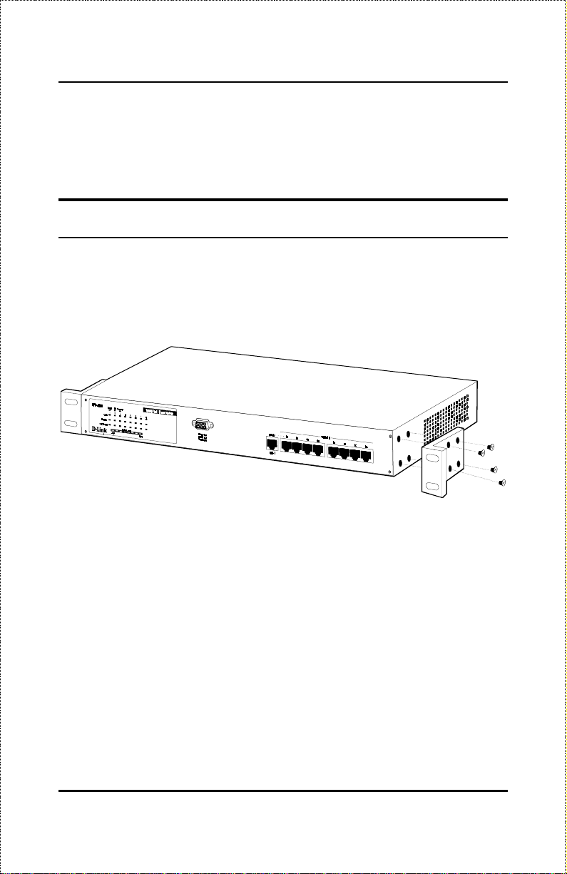
Rack Installation
The DES-3208 can be mounted in an EIA standard size, 19-inch rack, which
can be placed in a wiring closet with other equipment. To install, attach the
mounting brackets on the switch’s front panel (one on each side) and secure
them with the screws provided.
Figure 2- 2A. A ttaching the mounting brackets to the 10/100 Fast
Ethernet Switch
Then, use the screws provided with the equipment rack to mount the Switch
in the rack.
Unpacking and Setup
7
Page 22
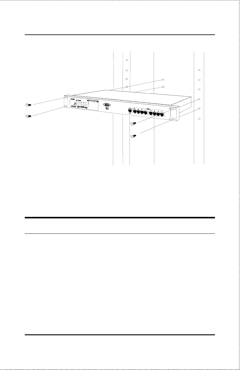
10/100 Fast Ethernet Switch User’s Guide
Figure 2-2B. Installing the 10/100 Fast Ethernet Switch in an
equipment rack
Power on
The DES-3208 Switch can be used with AC power sources 100 - 240 VAC,
50 - 60 Hz. The power switch is located at the rear of the unit adjacent to the
AC power connector and the system fan. The Switch’s power supply will
adjust to the local power source automatically and may be turned on without
having any or all LAN segment cables connected.
After the power switch is turned on, the LED indicators should respond as
follows:
All LED indicators will momentarily blink . This blink ing of the LED
♦
indicators represents a reset of the system.
8
Unpacking and Setup
Page 23

10/100 Fast Ethernet Switch User’s Guide
The FDX/Col LED indicators blink from
♦
The power LED indicator will light yellow while the switch loads
♦
onboard software and performs a self-test. After approximately 20
seconds, the LED will light green to indicate the switch is in a ready
state.
The console LED indicator will remain ON if there is a connection at
♦
the RS-232 port, otherwise this LED indicator is
The MII LED indicator will remain ON if there is a connection at the
♦
MII port, otherwise this LED indicator is
connection at the MII port, The MII LED, and the 100M and Link/Act
LED indicators for port 2x will remain ON, otherwise the Link/Act
LED indicators are OFF. The 100M LED indicator may remain ON
or OFF depending on the transmission speed.
The System Load LED indicators will momentarily b lin k.
♦
yellow to green
.
OFF
. If there is an active
OFF
.
Power Failure
As a precaution, the Switch should be turned
When power is resumed, turn the Switch ON. At all times, av oid leaving the
Switch ON after the occurrence of a power failure.
OFF
in case of power failure.
Unpacking and Setup
9
Page 24

10/100 Fast Ethernet Switch User’s Guide
3
3 I
This chapter describes the front panel, rear panel and LED indicators of the
Switch
DENTIFYING
E
XTERNAL
C
OMPONENTS
Front Panel
The front panel of the Switch consists of 8 (10/100 Mbps) MDI-X ports, 1
uplink (MDI-II) port, a RS-232 communication port and LED indicators.
Figure 3-1. Front panel view of the DES-3208 Switch
8 high performance N-way (MDI-X) ports all operating at 10/100
♦
Mbps for connection to servers and hubs. All ports can be autonegotiated between 10Mbps or 100Mbps.
10
Identifying External Components
Page 25
10/100 Fast Ethernet Switch User’s Guide
Port 2x (Port number two) is a shared connection with the (Media
♦
Independent Interface) MII port in the back of the Switch. Note that,
whenever there is a connection at the MII port, port 2x is unavailable
for connection to other devices.
Uplink/ MDI-II (media dependent interface) port for uplink to
♦
another switch, hub or repeater.
RS-232 DCE console port for diagnosing the Switch via a connection
♦
to a PC and Local Console Management.
Comprehensive LED indicators that display the conditions of the
♦
Switch and status of the network. A description of these LED
indicators follow (see
LED Indicators
).
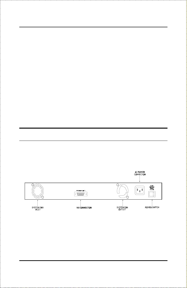
Rear Panel
The rear panel of the Switch consists of a power switch, an AC power
connector, system fans and MII port. The following shows the rear panel of
the Switch.
Figure 3-2. Rear panel view of the DES-3208
Power Switch.
♦
system, press the switch to the “ 1” position; to turn off, press the
switch to the “0” position.
Identifying External Components
This turns the Switch on and off. To turn on the
11
Page 26

10/100 Fast Ethernet Switch User’s Guide
AC Power Connector.
♦
supports the power cord. Plug in the female connector of the
provided power cord into this connector, and the male into a power
outlet. Supported input voltages range from 100 ~ 240 VAC at 50 ~
60 Hz.
System Fan.
♦
also to dissipate heat. The sides of the system also provide heat vents
to serve the same purpose. Do not block these openings, and leave
adequate space at the rear and sides of the Switch for proper
ventilation. Be reminded that without proper heat dissipation and air
circulation, system components might overheat, which could lead to
system failure.
MII Connector.
♦
connector is a 40 pin connector for use with flexible media (e.g. fiber
cable).
This connector has a shared connection with port 2x, and when
connected, the MII connector takes operational precedence over port
2x.
If you are using a 100BASE-FX Transceiver, This connector is
◊
used for connection between two independent locations up to a
distance of
These fan are used to circulate air inside the Switch and
two kilometers
This is a three-pronged connector that
The MII (Media Independent Interface) interface
.
If you are using a 100BASE-TX Transceiver, this connector is
◊
used for connection between two independent location up to a
distance of
When you are connecting a 100BASE-FX or TX Transceiver to the
MII connector prior to making cable connections, make sure that the
100BASE-FX or TX Transceiver address setting is set to “ 2,” (See
the Transceiver manufacturer user’s guide for more information). The
pin specifications for this connector appear in
Note
: When making cable or transceiver connections
100 meters
.
Appendix C
to the MII inteface connector, make sure that
12
Identifying External Components
Page 27
10/100 Fast Ethernet Switch User’s Guide
the the Switch is
turned off
after connecting
turn the Switch on. When disconnecting a
cable or transceiver from the MII interface
connector,
turn off
the Switch then disconnect
the cable or transceiver.
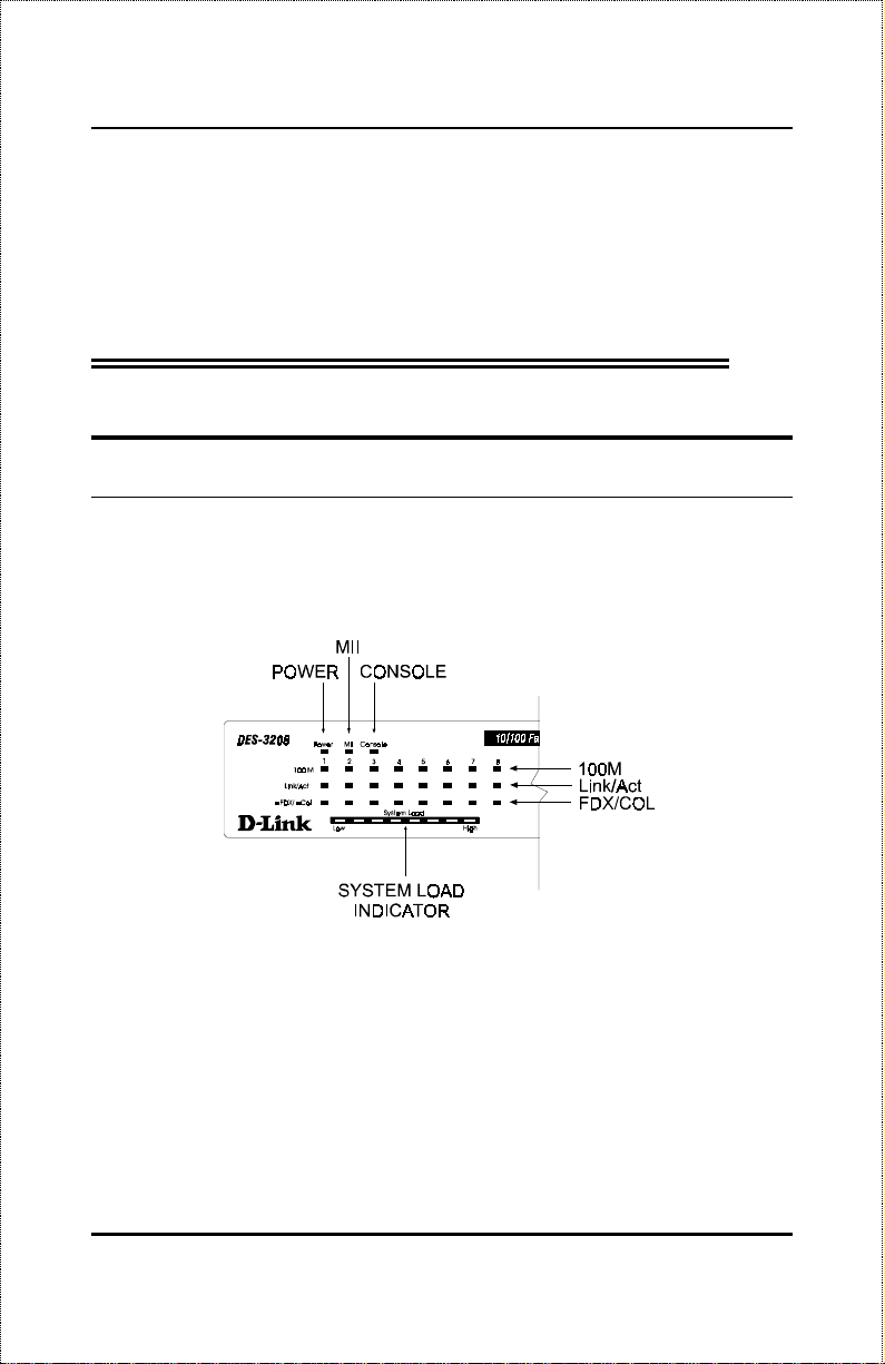
LED Indicators
The LED indicators of the Switch include Power, MII, Console, 100 M,
Link/Act FDX/Col and System Load. The following shows the LED
indicators for the Switch along with an explanation of each indicator.
Figure 3-3. The DES-3208 Switch LED indicators
Power
♦
♦
Identifying External Components
. After turning on the power, the Power indicator, on the front
panel, should light yellow to indicate the switch is loading onboard
software and performing a self-test. After approximately 20 seconds,
the green LED lights to indicate the ready state of the switch.
MII.
The MII (Media Independent Interface) is used for connection
between two independent locations up to a distance of two kilometers.
13
Page 28

10/100 Fast Ethernet Switch User’s Guide
After the system’s initial check and power is on , this LED in dicator is
ON
(
) when a secured connection is established at the port,
green
otherwise it is
OFF
.
♦
Console.
This LED indicator is lit when the switch is being managed
via out-of-band/ local console management through the RS-232
console port using a straight-through serial cable. When a secured
connection is established, this LED ind icator is lit
. Otherwise, it
green
is OFF.
100 M
♦
. These LED indicators are illuminated (
) when a 100
green
Mbps device is connected to any of the 8 ports or uplink port. If a 10
Mbps device is connected to any of the 8 ports or uplink port, these
LED indicators are
Link/Act
♦
. These LED indicators are lighted up (
OFF
.
) when there is
green
a secure connection (or link) to a device at any of the ports. The LED
indicators blink (
) whenever there is reception or transmission
green
(i.e. Activity--Act) of data occurring at a port.
FDX/Col
♦
. This LED indicator is
when a respective port is in
green
full duplex (FDX) mode. Otherwise, it is OFF for half duplex (HDX)
operations. It blinks
when collisions are occurring on the
yellow
respective port.
System Load.
♦
Indicates the current traffic load on the Switch. The
system load bar provides a quick reference of the current traffic load
relative to the capacity. It is a measure of the number of packets
traversing within the device. Only valid packet and transmit packet
are counted. The first six LED indicators are
indicators are
yellow
.
; the last two LED
green
14
Identifying External Components
Page 29

10/100 Fast Ethernet Switch User’s Guide
4
4 C
This chapter describes how to connect the DES-3208 to your Fast Ethernet
network.
ONNECTING THE
S
WITCH
PC to Switch
A PC can be connected to the Switch via a two-pair Category 3, 4, 5 UTP
/STP straight cable. The PC (equipped with a RJ-45 10/100 Mbps jack)
should be connected to any of the eight ports (1x - 8x) of the DES-3208.
Figure 4-1. DES-3208 Switch connected to a PC or Workstation
Connecting The Switch
15
Page 30

10/100 Fast Ethernet Switch User’s Guide
The LED indicators for PC connection are dependent on the LAN card
capabilities. If LED indicators are not illuminated after making a proper
connection, check the PC’s LAN card, the cable, Switch conditions and
connections.
The following are LED indicator possibilities for a PC to Switch connection:
1.
The 100M LED indicator comes ON for a 100 Mbps and stays OFF
for 10 Mbps.
2.
The Link/Act LED indicator lights up upon hookup.
3.
The FDX/Col LED indicator depends upon LAN card capabilities.
Hub to Switch
A 10Base-T hub can be connected to the Switch via a two-pair
♦
Category 3, 4 or 5 UTP/STP straight cable.
A 100Base-TX hub can be connected to the Switch via a two-pair
♦
Category 5 UTP/STP straight cable.
The connection is accomplished from the hub’s uplink (MDI-II) port to any
of the Switch’s (MDI-X) ports 1x - 8x of the DES-3208.
Figure 4-2. DES-3208 Switch connected to a 10BASE-T or
100Base-TX Hub
16
Connecting The Switch
Page 31

10/100 Fast Ethernet Switch User’s Guide
10Base-T Hub
For a 10 Base-T hub, the Switch’s LED indicators should illuminate the
following:
100M LED speed indicator is
♦
Link/Act indicator is ON.
♦
FDX/Col indicator is OFF.
♦
OFF.
100Base-TX Hub
For a 100Base-TX hub, the Switch’s LED indicators should illuminate the
following:
100M LED speed indicator is
♦
Link/Act is ON.
♦
FDX/Col LED indicator is OFF.
♦
ON.
Hub without Uplink (MDI-II) port
If a hub is not equipped with an uplink (MDI-II) port, then connection can
be made using either straight cable or crossover cable (see
Technical Specifications
Connecting The Switch
for cable requirements).
Appendix A
17
,
Page 32

10/100 Fast Ethernet Switch User’s Guide
Figure 4-3. DES-3208 Switch connected to a Hub without uplink
(MDI-II) port using the Straight OR crossover cable option
Using straight cable
When using straight cable, the connection can be made from the uplink
(MDI-II) port of the Switch to any port of the Hub (see figure 4-3).
Using crossover cable
When using crossover cable, the connection can be made from any (1x - 8x)
port of the Switch to any port of the Hub (see figure 4-3).
Switch to Switch (other devices)
The Switch can be connected to another switch or other devices (routers,
bridges, etc.) via a two-pair Category 3, 4, 5 UTP/STP straight or crossover
cable.
18
Connecting The Switch
Page 33

10/100 Fast Ethernet Switch User’s Guide
Figure 4-4. DES-3208 Switch to switch connection using the
straight OR crossover cable options.
Using straight cable
When using straight cable, this is done from the uplink (MDI-II) port of the
Switch (Switch A) to any of the 10 Mbps or 100 Mbps (MDI-X) port of the
other switch (switch B) or other devices (see figure 4-4).
Using crossover cable
When using crossover cable, this is done from any (MDI-X) port of the
Switch (Switch A) to any of the 10 Mbps or 100 Mbps (MDI-X) port of the
other switch (switch B) or other devices (see figure 4-4).
Switch A’s LED indicators for the respective connected ports are as follows:
100M is ON for 100Mbps, otherwise OFF.
♦
Link/Act is ON.
♦
FDX/Col depends on the connected switch or other device.
♦
Connecting The Switch
19
Page 34

10/100 Fast Ethernet Switch User’s Guide
5
5 S
WITCH
M
ANAGEMENT
Local Console Managament
Local console management involves the administration of the DES-3208
Switch via a direct connection to the RS-232 DCE console port. From the
Main Menu screen of the console program, a Super User or General User
(defined in the next chapter) has priviledge and access to manage, control
and monitor the many functions of the Switch.
The components of the Switch allow them to be part of a manageable
network. These components include a CPU, memory for data storage, other
related hardware and the SNMP agent firmware. Activities on the Switch
can be monitored with these components, while the Switch can be
manipulated to carry out specific tasks.
Out-of-Band Management for the Switch is accomplished through a locally
connected management terminal to the RS-232 console port. Through this
port, a user can set up, monitor, or change the configuration of the Switch.
The Spanning Tree Algorithm (STA) provides the capability for the Switch
to operate properly with other Bridges in a SNMP network supporting the
STA. Using the STA, the network will prevent network loop, and
automatically establish and activate a backup path in the event of a path
failure.
20
Switch Management
Page 35

10/100 Fast Ethernet Switch User’s Guide
Console port (RS-232 DCE
Out-of-band )management requires connecting a PC (with a SNMP
management platform) to the RS-232 DCE console port of the Switch.
Switch management using terminal emulation/ VT100 when connected to the
RS-232 DCE console port is called
differentiate it from management done via management platforms.
The console port is set for the following configuration:
Baud rate: 9,600
◊
Parity: none
◊
Data width: 8 bits
◊
Stop bits: 1
◊
Local Console Managment
to
IP Addresses and SNMP Community
Names
Each Switch has its own IP Address, which is used for communication with
an SNMP network manager or other TCP/IP application (for example
BOOTP, TFTP). You can change the default Switch IP Address to meet the
specification of your networking address scheme.
In addition, you can also set in the Switch an IP Address for a gateway or a
router. It is useful when the network management station is not located on
the same network as the Switch, making it necessary for the Switch to go
through a gateway or router to reach the network manager.
For security, you can set in the Switch a list of IP Addresses of the network
managers that you allow to manage the Switch. You can also change the
default Community Name in the Switch and set access rights of these
Community Names.
Switch Management
21
Page 36

10/100 Fast Ethernet Switch User’s Guide
Traps
Trap managers are special users of the network who are given certain rights
and access in overseeing the maintenance of the network. Trap managers can
receive traps sent from the Switch; they must immediately take certain
actions to avoid future failure or breakdown of the network.
Traps are messages that alert you of events that occur on the Switch. The
events can be as serious as a reboot (someone accidentally turned OFF the
Switch), or less serious like a port status change. The Switch generates traps
and sends them to the network manager (trap managers). The following lists
the types of events that can take place on the Switch.
System resets
◊
Errors
◊
Status changes
◊
Topology changes
◊
Operation
◊
You can also specify which network managers may receive traps from the
Switch by setting a list of IP Addresses of the authorized network managers.
The following are trap types a trap manager will receive:
Cold Start
♦
and initialized such that software settings are reconfigured and
hardware systems are rebooted. A cold start is different from a
factory reset.
Authentication Failure
♦
manager/ user) on the Switch is not a valid user of the Switch and may
have entered an incorrect community name.
New Root
♦
root of the Spanning Tree, the trap is sent by a bridge soon after its
22
: This trap signifies that the Switch has been powered up
: This trap signifies that an addressee (or
: This trap indicates that the Switch has become the new
Switch Management
Page 37

10/100 Fast Ethernet Switch User’s Guide
election as the new root. This implies that upon expiration of the
Topology Change Timer the new root trap is sent out immediately
after the Switch’s selection as a new root.
Topology Change
♦
when any of its configured ports tranisitions from the Learning state
to the Forwarding state, or from the Forwarding state to the Blocking
state. The trap is not sent if a new root trap is sent for the same
transition.
Link Change Event
♦
changes from link up to link down or from link down to link up.
Port Partition
♦
partition mode (or automatic partitioning, port disable) when more
than thirty-two collisions occur while transmitting.
: A Topology Change trap is sent by the Switch
: This trap is sent whenever the link of a port
: This trap is sent whenever the port state enter the
MIBs
The information stored in the Switch is known as the Management
Information Base (MIB). The Switch uses the standard MIB-II Management
Information Base module. Consequently, MIB values inside the Switch can
be retrieved from any SNMP-based network manager. In addition to the
standard MIB-II, the Switch also supports its own proprietary enterprise MIB
as an extended Management Information Base. These MIBs may also be
retrieved by specifying the MIB’s Object-Identity (OID) at the network
manager. MIB values can be either read-only or read-write.
Read-only MIBs variables can be either constants that are programmed into
the Switch, or variables that change while the Switch is in operation.
Examples of read-only constants are the number of ports and types of ports.
Examples of read-only variables are the statistics counters such as the
number of errors that have occurred, or how many kilobytes of data have
been received and forwarded through a port.
Switch Management
23
Page 38

10/100 Fast Ethernet Switch User’s Guide
Read-write MIBs are variables usually related to user-customized
configurations. Examples of these are the Switch’s IP Address, Spanning
Tree Algorithm parameters and port status.
If you use a third-party vendors’ SNMP software to manage the Switch, a
diskette listing the Switch’s propriety enterprise MIBs can be obtained by
request. If your software provides functions to browse or modify MIBs, you
can also get the MIB values and change them (if the MIBs’ attributes permit
the write operation). This process however can be quite involved, since you
must know the MIB OIDs and retrieve them one by one.
Packet Forwarding
The Switch looks at the network configuration to forward packets. This
reduces the traffic congestion on the network, because packets, instead of
being transmitted to all segments, are transmitted to the destination only.
Example: if Port 1 receives a packet destined for Port 2, the Switch
transmits that packet through Port 2 only, and transmits nothing through Port
1.
Filtering Database.
♦
frames received by a Switch Port to other Ports on that Switch, in
order to prevent the duplication of frames. Frames transmitted
between a pair of end stations can be confined to LANs that form a
path between those end stations.
The functions that support the use and maintenance of filtering
database information are:
1.
Permanent configuration of reserved addresses.
2.
Explicit configuration of static filtering in formation.
3.
Automatic learning of dynamic filtering information through
observation of Switched Local Area Network traffic.
4.
Aging out of filtering information that has been automatically learned.
24
A Switch filters frames, i.e., does not relay
Switch Management
Page 39

10/100 Fast Ethernet Switch User’s Guide
5.
Calculation and configuration of Switched Local Area Network
topology.
Aging Time
The Aging Time is a parameter that affects the auto-learn process of the
Switch in terms of the network configuration. Dynamic Entries, which make
up the auto-learned-node address, are aged out of the address table according
to the Aging Time that you set.
The Aging Time can be from 10 seconds to 1,000,000 seconds. A very long
Aging Time can result with the out-of-date Dynamic Entries that may cause
incorrect packet filtering/forwarding decisions.
In the opposite case, if the Aging Time is too short, many entries may be
aged out soon, resulting in a high percentage of received packets whose
source addresses cannot be found in the address table.
Spanning Tree Algorithm
The Spanning Tree Algorithm (STA) in the Switch allows you to create
alternative paths (with multiple switches or other types of bridges) in your
network. These backup paths are idle until the Switch determines that a
problem has developed in the primary paths. When a primary path is lost,
the Switch providing the alternative path will auto matically go into service
with no operator intervention. This automatic network reconfiguration
provides maximum uptime to network users. The concept of the Spanning
Tree Algorithm is a complicated and complex subject and must be fully
researched and understood. Please read the following before making any
changes .
Network loop detection and prevention.
♦
With STA, there will be only one path between any two LANs. If
there is more than one path, forwarded packets will loop indefinitely.
STA detects any looped path and selects the path with the lowest path
Switch Management
25
Page 40

10/100 Fast Ethernet Switch User’s Guide
cost as the active path, while blocking the other path and using it as
the backup path.
Automatic topology re-configuration.
♦
When the path for which there is a backup path fails, the backup path
will be automatically activated, and STA will automatically reconfigure the network topology.
STA Operation Levels
STA operates on two levels: the bridge level and the port level. On the
bridge level, STA calculates the Bridge Identifier for each Switch, then sets
the Root Bridge and the Designated Bridges. On the port level, STA sets the
Root Port and Designated Ports. Details are as follows:
On the Bridge Level
Root Bridge
♦
Bridge. Naturally, you will want the Root Bridge to be the best
Switch among the Switches in the loop to ensure the highest network
performance and reliability.
Bridge Identifier
♦
parameter that you can set) and the MAC address of the Switch.
Example: 4 00 80 C8 00 01 00, where 4 is the Bridge Priority. A
lower Bridge Identifier results in a higher priority for the Switch, and
thus increases it probabily of being selected as the Root Bridge.
Designated Bridge
♦
that has the lowest Root Path Cost to the Root Bridge is the
Designated Bridge. It forwards data packets for that LAN segment.
In cases where all Switches have the same Root Path Cost, the
Switch with the lowest Bridge Identifier becomes the Designated
Bridge.
26
: The Switch with the lowest Bridge Identifier is the Ro ot
: This is the combination of the Bridge Prio rity (a
: From each LAN segment, the attached Bridge
Switch Management
Page 41

10/100 Fast Ethernet Switch User’s Guide
Root Path Cost
♦
Path Cost of the Root Port and the Root Path Costs of all the
Switches that the packet goes through. The Root Path Cost of the
Root Bridge is zero.
Bridge Priority
♦
the number you set, the higher the Bridge Priority is. the higher the
Bridge Priority, the better the chance the Switch will be selected as
the Root Bridge.
: The Root Path Cost of a Switch is the sum of the
: This is a parameter that users can set. The smaller
On the Port Level
Root Port
♦
lowest Path Cost to the Root Bridge. In case there are several such
ports, then the one with the lowest Port Iden tifier is the Root Port.
Designated Port
♦
attached to the LAN segment for which the Switch is the Designated
Bridge.
Port Priority
♦
is. With higher Port Priority, the highe r the probability that the po rt
will be selected as the Root Port.
Path Cost
♦
according to the STA specification. The 100Mbps segment has an
assigned Path Cost of 10, and each 10Mbps segment has an assigned
Path Cost of 100, based on the STA specifications.
: Each Switch has a Root Port. This is the port that has the
: This is the port on each Designated Bridge that is
: The smaller this number, the higher the Port Priority
: This is a changeable parameter and may be modified
User-Changeable Parameters
The factory default setting should cover the majority of installations.
However, it is advisable to keep the default settings as set at the factory;
unless, it is absolutely necessary. The user changeable parameters in the
Switch are as follows:
Switch Management
27
Page 42

10/100 Fast Ethernet Switch User’s Guide
Bridge Priority
♦
. A Bridge Priority can be from 0 to 65535. 0 is
equal to the highest Bridge Priority.
Bridge Hello Time
♦
. The Hello Time can be from 1 to 10 seconds.
This is the interval between two transmission s of BPDU packets sent
by the Root Bridge to tell all other Switches that it is indeed the Root
Bridge. If you set a Hello Time for your Switch, and it is not the Root
Bridge, the set Hello Time will be used if and when your Switch
becomes the Root Bridge.
Note that the Hello Time cannot be longer than the Max. Age.
Otherwise, a configuration error will occur.
Bridge Max. Age
♦
. The Max. Age can be from 6 to 40 seconds. At
the end of the Max. Age, if a BPDU has still not been received from
the Root Bridge, your Switch will start sending its own BPDU to all
other Switches for permission to become the Root Bridge. If it turns
out that your Switch has the lowest Bridge Identifier, it will become
the Root Bridge.
Bridge Forward Delay
♦
. The Forward Delay can be from 4 to 30
seconds. This is the time any port on the Switch spends in the
listening state while moving from the blocking state to the
forwarding state.
Observe the following formulas when you set the above parameters:
1. Max. Age • 2 x (Forward Delay - 1 second)
2. Max. Age • 2 x (Hello Time + 1 second)
Port Priority
♦
: A Port Priority can be from 0 to 255. The lower the
number, the greater the probability the port will be chosen as the
Root Port.
28
Switch Management
Page 43

10/100 Fast Ethernet Switch User’s Guide
Illustration of STA
A simple illustration of three Bridges (or the Switch) connected in a loop is
depicted in
network problems if the STA assistance is not applied. For instance, if
Bridge 1 broadcasts a packet to Bridge 2, Bridge 2 will broadcast it to
Bridge 3, and Bridge 3 will broadcast it to Bridge 1...and so on. The
broadcast packet will be passed indefinitely in a loop, causing a serious
network failure.
Figure 5-1
. In this example, you can anticipate some major
To alleviate network loop problems, STA can be applied as shown in
5-2. In this example, STA breaks the loop by blocking the connection
between Bridge 1 and 2. The decision to block a particular connection is
based on the STA calculation of the most current Bridge and Port settings.
Now, if Bridge 1 broadcasts a packet to Bridge 3, then Bridge 3 will
broadcast it to Bridge 2 and th e broadcast will end there.
STA setup can be somewhat complex. Therefore, you are advised to keep
the default factory settings and STA will automatically assign root
bridges/ports and block loop connections. However, if you need to
customize the STA parameters, refer to
Table 5-1
.
Figure
Switch Management
29
Page 44

10/100 Fast Ethernet Switch User’s Guide
Figure 5-1. Before Applying the STA Rules
30
Figure 5-2. After Applying the STA Rules
Switch Management
Page 45

10/100 Fast Ethernet Switch User’s Guide
STA parameters Settings Effects Comment
Bridge Priority
Hello Time
Max. Age Time
Forward Delay
Enable / Disable
Port Priority
lower the #,
higher the
priority
1 - 10 sec. No effect, if not
6 - 40 sec. Compete for Root
4 - 30 sec. High # delays the
Port Level STA parameters
Enable /
Disable
lower the #,
higher the
priority
Table 5-1. User-selective STA parameters
Increases chance of
becoming the Root
Bridge
Root Bridge
Bridge, if BPDU is
not received
change in state
Enable or disable
this LAN segment
Increases chance of
become Root Port
Avoid, if the switch is
used in workgroup level
of a large network
Never set greater than
Max. Age Time
Avoid low number for
unnecessary reset of
Root Bridge
Max. Age ≤ 2 x
(Forward Delay - 1)
Max. Age ≥ 2 x (Hello
Time + 1)
Disable a port for
security or problem
isolation
Switch Management
31
Page 46

10/100 Fast Ethernet Switch User’s Guide
6
6 U
Your 10/100 Fast Ethernet Switch supports a console management interface
that allows you to set up and control your Switch, either with an ordinary
terminal (or terminal emulator), or over the network using the TCP/IP
TELNET
management functions. In addition, the console program will allow you to
set up the Switch for management using D-View, SNMP-View or another
SNMP-based network management system. This chapter describes how to
use the console interface to access the Switch, change its settings, and
monitor its operation.
SING THE
protocol. You can use this facility to perfo rm many b asic networ k
C
ONSOLE
I
NTERFACE
Connecting to the Switch
You can use the console interface by connecting the Switch to a VT100compatible terminal or a computer running an ordinary terminal emulator
program (e.g., the
system) using an RS-232C serial cable. Your terminal parameters will need
to be set to:
terminal
program included with the Windows operating
VT-100/ANSI compatible
♦
Arrow keys enabled
♦
32
Using the Console Interface
Page 47

9,600 baud
♦
8 data bits
♦
No parity
♦
One stop bit
♦
10/100 Fast Ethernet Switch User’s Guide
You can also access the same functions over a
you have set an IP address for your Switch, you can use a
(in a VT-100 compatible terminal mode) to access and control the Switch.
All of the screens are for the most part identical, whether accessed from the
console port or from a
TELNET
interface.
TELNET
interface. Once
TELNET
program
Console Usage Conventions
The console interface makes use of the following conventions:
1.
Items after a colon
information purposes. The cursor cannot be moved to these items.
2.
Items in
bar.
3.
Items in
You can use the backspace and delete keys to erase characters behind
and in front of the cursor.
4.
The up and down arrow keys, the left and right arrow keys, the tab
key and the backspace key, can be used to move between selected
items. It is recommended that you use the
for moving around console.
<
angle brackets
[
square brackets
are read-only values, displayed for
”:”
can be toggled on or off using the space
>
can be changed by typing in a new value.
]
and
tab key
backspace key
5.
Items in UPPERCASE are commands. Moving the selection to a
command and pressing Enter will execute that com mand, e.g. SAVE,
EXIT, etc.
Using the Console Interface
33
Page 48

10/100 Fast Ethernet Switch User’s Guide
First Time Connecting To The Switch
The Switch supports user-based security that can allow you to prevent
unauthorized users from accessing the Switch or changing its settings. This
section tells how to log onto the Switch.
Note: The passwords used to access the Switch are case
sensitive; therefore, “S” is not the same as “s.”
When you first connect to the Switch, you will be presented with the first
login screen (shown below).
press the R key, and release both keys) to call up the screen, if the
first login screen does not appear. Also Ctrl+R can be used at any
time to refresh the screen.
Press Ctrl+R (hold down the Ctrl key,
Figure 6-1. Initial Screen, first time connecting to the Switch
Move the cursor to OK and press Enter (Note:
Password
fields blank
). You will see the
Main Menu
34
Leave the
Using the Console Interface
User Name
shown below:
and
Page 49

10/100 Fast Ethernet Switch User’s Guide
Figure 6-2. Main Menu for Super User
The first user automatically gets super user privileges
and is recommended to create at least one Super User for the Switch.
(See
Table 6-1
)
Steps to create a Super User or General User:
From the screen above, move the cursor to the
press Enter, then the
1.
Choose
Create New User Menu
2.
Enter the new user name, and assign an initial password. Determine
whether the new user should have
privileges.
3.
Choose
4.
Choose
Create New User
SAVE
EXIT
User Account Change Menu
User Account Change Menu
to let the user addition take effect.
and press
to leave the
from the
appears.
Enter
Create New User menu
User Account Change
appears.
Super User
or
.
and
and the
General User
Super and General User Privileges
There are two levels of user privileges:
menu selections available to users with
Super User
Super User
and
General User
privileges may not be
. Some
Using the Console Interface
35
Page 50

10/100 Fast Ethernet Switch User’s Guide
available to
with
Super User
General User
and
s. The main menus shown are the menus for users
General User
privileges:
Figure 6-3. Main Menu for Super User
Figure 6-4. Main Menu for General User
The following table summarizes Super User and General User privileges:
Menu Super User General User
Privilege
36
Using the Console Interface
Page 51

10/100 Fast Ethernet Switch User’s Guide
Menu Super User General User
Privilege
System Config. Yes Yes, view only.
TCP/IP Parameter Configuration Yes Yes, view only.
Statistic Counters Yes Yes .
Port Configuration Yes Yes, view only.
Spanning Tree Algorithm Parameters
Forwarding Table Yes Yes, view only.
Custom Filtering Table Yes Yes, view only.
Protocol Parameters Yes Yes, view only.
STAP Port Parameters Yes Yes, view only.
Out-of-Band/ Console Configuration Yes Yes, view only.
User Account Change
Create New User Yes No
Change Access/ Delete Users Yes No
Change Password Yes Yes
SNMP Trap Manager Configuration Yes Yes, view only.
SNMP Manager Config. Yes Yes, view only.
System Reset Yes No
Software Update Yes No
Factory Reset NV-RAM to Default Value Yes No
Table 6-1. Super User and General User Privileges
Using the Console Interface
37
Page 52

10/100 Fast Ethernet Switch User’s Guide
establishing a
issue a
Super User
LOGOFF
, you are now ready to operate the Switch. Now
command from the main menu, the login screen
1
appears
as follows.
LOGIN ON THE SWITCH CONSOLE
BY REGISTERED USERS
Figure 6-5. Login Screen
To log in,
1.
Type in your user name and press Enter.
2.
Type in your password and press Enter.
4
If the Switch is not used within five (5) minutes, the following message appears at the bottom
of the console’s main menu: “Console time out press ENTER to continue...” At this time,
press ENTER and login screen will be displayed.
38
Using the Console Interface
Page 53

10/100 Fast Ethernet Switch User’s Guide
3.
With the cursor on the OK selection, press Enter. The main menu
screen will be displayed based on your Super User or General User
access level or privilege.
The following describes the differences between the user privileges.
Changing Your Password
To change your user password:
1.
Choose
User Account Change
from the main menu.
2.
Choose
3.
Type in your
4.
Type in your
5.
Type in the new password you have chosen, and press Enter. Type in
the same new password in the following blank to verify that you have
not mistyped it.
6.
Choose the SAVE command to let the password change take effect.
Change Password
Figure 6-6. Change Password
user name
old password
and press Enter.
and press Enter.
.
Using the Console Interface
39
Page 54

10/100 Fast Ethernet Switch User’s Guide
7.
Choose EXIT to exit this screen.
This method can also be used by a
password.
Super User
to change another user’s
Adding and Deleting Users
Access to the console, whether using the console port or via
controlled using a user name and password. Up to three of these user names
can be defined. The console interface will not let you delete the current
logged-in user, however, in order to prevent accidentally deleting all of the
users with
Only users with the
Super User
privilege.
Super User
privilege can add new and delete users.
TELNET
Adding a New User
To add a new user:
1.
Choose
User Account Change
from the main menu.
, is
2.
40
Choose
Figure 6-7. User Account Change Menu
Create New User
from the User Account Change menu.
Using the Console Interface
Page 55

10/100 Fast Ethernet Switch User’s Guide
3.
Enter the new user name, and assign an initial passwo rd. Determine
whether the new user should have
Super User
or
General User
privileges.
Figure 6-8. Adding a New User
4.
Choose SAVE and press Enter to let the user addition take effect.
5.
Choose EXIT to leave the Create New User menu.
Deleting a User
To delete a user,
1.
Choose
2.
Choose
3.
Toggle the Delete field of the user you wish to remove to Yes.
Using the Console Interface
User Account Change
Delete Users
from the User Account Change menu.
from the main menu.
41
Page 56

10/100 Fast Ethernet Switch User’s Guide
Figure 6-9. Deleting a User
4.
Choose SAVE and press Enter to let the user addition take effect.
5.
Choose EXIT to leave the Delete Users menu.
Setting up the Switch
This section describes the settings you will need to change to allow you to be
able to manage the Switch from an SNMP-based Network Management
System such as D-View, SNMP-View, or to be able to access the Switch
using the
TELNET
TCP/IP Settings
The Switch needs to have a TCP/IP address assigned to it so that the network
management system or
TCP/IP Parameters Configuration
for the two different interfaces used on the Switch: the Ethernet interface
42
protocol.
TELNET
client can find it on the network. The
menu allows you to change the settings
Using the Console Interface
Page 57

10/100 Fast Ethernet Switch User’s Guide
used for in-band communication, and the SLIP interface used over the
console port for out-of-band communication.
Each of the fields on this menu takes effect the next time the system is
restarted. Fields that can be set include:
IP Address:
♦
receiving SNMP and
form
xxx.xxx.xxx.xxx
determines the IP address used by the Switch for
TELNET
, where each
communications. Should be of the
is a number (represented in
xxx
decimal) between 0 and 255. This address should be a unique address
on a network assigned to you by the central Internet authorities. The
same IP address is shared by both the SLIP and Ethernet network
interfaces.
Subnet Mask:
♦
the Switch is on. Should be of the form
is a number (represented in decimal) between 0 and 255. If no
xxx
bitmask that determines the extent of the subnet that
xxx.xxx.xxx.xxx
, where each
subnetting is being done, the value should be 255.0.0.0 for a Class A
network, 255.255.0.0 for a Class B network, and 255.255.255.0 for a
Class C network.
Default Gateway:
♦
IP address that determines where frames with a
destination outside the current subnet should be sent. This is usually
the address of a router or a host acting as an IP gateway. If your
network is not part of an internetwork, or you do not want the Switch
to be accessible outside your local network, you can leave this field
blank.
Send BOOTP Request Upon Power Up:
♦
determines whether the
Switch should send out a BOOTP broadcast request when it is
powered up. The BOOTP protocol allows IP addresses, network
masks, and default gateways to be assigned on a central BOOTP
server; if this option is set the Switch will first look for a BOOTP
server to provide it with this information before using the supplied
settings.
Using the Console Interface
43
Page 58

10/100 Fast Ethernet Switch User’s Guide
Figure 6-10. TCP/IP Parameters Configuration Menu
Out-of-band management and console
settings
You can use the
use the Switch’s RS-232C serial port for console management or for out-ofband TCP/IP communications using SLIP, and to set the bit rate used for
SLIP communications.
The following fields can be set:
System Restart Setting:
Serial Port Type:
♦
for out-of-band (SLIP) management or for console management,
starting from the next time the Switch is restarted. In this field, yo u
can toggle between
Out-of-Band Baud Rate:
♦
be used the next time the Switch is restarted. Applies only when the
serial port is being used for out-of-band (SLIP) management; it does
not apply when the port is used for the console port. Available speeds
are 2400, 9600, 19200 and 38,400 bits per second..
44
Out-of-Band/Console Setting
determines whether the serial port should be used
Out-of-band
determines the serial port bit rate that will
Console
or
menu to choose whether to
port type settings.
Using the Console Interface
Page 59

10/100 Fast Ethernet Switch User’s Guide
Figure 6-11. Out-of-Band/Console Setting Menu
Software Updates
The Switch is capable of obtaining its boot-time configuration information,
as well as updated versions of its internal firmware, using TFTP (the Trivial
File Transfer Protocol) and BOOTP (the BOOTstrap Protocol). You can use
the Software Update menu to control this featur e.
The fields you can set in this menu are:
Software Update
♦
look for a configuration file over the network. If set to Disable, none
of the fields below have any effect.
Software Update Mode
♦
Determines whether the configuration file should be obtained through
the Ethernet network or through the console port.
Boot Protocol:
♦
Applies only if the
Boot Server IP Address:
♦
the configuration file is located. This entry is used only if the
Software Update is set to enabled and your boot protocol is
Using the Console Interface
Determines whether or not the Switch will try to
Set to either
Set to either TFTP ONLY or
Software Update
The IP address of the TFTP server where
Network
is set to enabled.
Out-of-band
or
BOOTP&TFTP.
.
tftp
45
Page 60

10/100 Fast Ethernet Switch User’s Guide
only
. If you are using
Request on Power Up
is set to “Yes,” the address will be obtained from the BOOTP server.
Boot File Name:
♦
TFTP server. This entry is used only if your boot protocol is TFTP
ONLY; if you are using BOOTP&TFTP mode, the pathname will be
obtained from the BOOTP server.
The pathname of the configuration file on your
Figure 6-12. Software Update Menu
bootp-tftp
(see TCP/IP Parameters Configuration Menu)
mode, or if
Send BOOTP
System Configuration Menu
The System Configuration Menu screen shows various pieces of information
about your Switch, and allows you to set the System Name, System Location,
and System Contact. These settings can be retrieved from the Switch using
SNMP requests, allowing these settings to be used for network management
purposes. Each of these fields can contain up to 64 characters:
System Name:
♦
system.sysName
administrative purposes. The Switch’s fully qualified domain name is
often used, provided a name has been assigned.
46
corresponds to the SNMP MIB II variable
, and is used to give a name to the Switch for
Using the Console Interface
Page 61

10/100 Fast Ethernet Switch User’s Guide
System Location:
♦
system.sysLocation
location of the Switch for administrative purposes.
System Contact:
♦
sysContact
for the person responsible for administering the Switch.
The System Configuration Menu also contains the
Timeout
before the user is automatically “logged out.”
parameter, which determines how long the console may sit idle
corresponds to the SNMP MIB II variable
, and is used to indicate the physical
corresponds to the SNMP MIB II variable
, and is used to give the name and contact information
Figure 6-13. System Configuration Menu
Console/Telnet Display
SNMP Management Settings
SNMP Trap Manager Configuration
The Switch sends out SNMP
whenever certain exceptional events occur, such as when the Switch is turned
Using the Console Interface
to network management stations
traps
47
Page 62

10/100 Fast Ethernet Switch User’s Guide
on or when a system reset occurs. The Switch allows traps to be routed to up
to four different network management hosts.
For a detail list of Trap Types used for this Switch, see
Management, Traps
section.
Figure 6-14. SNMP Trap Manager Configuration Menu
The following trap parameters can be set:
IP Address:
♦
gives the IP address of the network management station
to receive the trap.
SNMP Community String:
♦
determines the SNMP community na me
to be included in the trap request.
Chapter 5, Switch
Status:
♦
determines whether this trap entry is valid or invalid. You
can delete an entry by changing its status to Invalid.
48
Using the Console Interface
Page 63

10/100 Fast Ethernet Switch User’s Guide
SNMP Manager Configuration
SNMP Security (Community Names)
SNMP (version 1) implements a rudimentary form of security by requiring
that each request includes a
arbitrary string of characters used as a “ password” to control access to the
Switch. If the Switch receives a request with a community name it does not
recognize, it will trigger an authentication trap.
The SNMP allows up to four different community names to be defined. The
community name
in addition to adding others. You will need to coor dinate these names with
the community name settings you use in your network management system.
The following SNMP Manager Configuration parameters can be set:
public
community name
is defined by default; you can change this name
. A community name is an
Access Rights:
♦
read only
Status:
♦
Using the Console Interface
determines whether this SNMP Community name entry is
valid or invalid.
allows each community to be separately set to either
or
read/write
Figure 6-15. SNMP Manager Configuration
.
49
Page 64

10/100 Fast Ethernet Switch User’s Guide
Port Configuration
The port configuration menu allows you to change the port state in the case
when you would like to partition a port due to excessive collision, or for
observation, device repair, security reasons. Great caution, however, must be
observed when partitioning a port; you should make sure that the partitioned
port is not being used as the port to control or monitor the condition of other
devices.
To change the configuration of a port:
1.
Choose
2.
Specify the port in the
3.
In the
4.
Choose SAVE and press Enter to let the changes take effect.
5.
Choose EXIT and hit the enter key to leave the Port Configuration
menu.
Port Configuration
Port State
field, change the port state to enable or disable.
Figure 6-16. Port Configuration Menu
from the main menu.
Port(1-8)
field.
Port Status, Media Speed (10/100Mbps) and Duplex Mode reflect the current
conditions of the port and are read-only fields and cannot be changed.
50
Using the Console Interface
Page 65

10/100 Fast Ethernet Switch User’s Guide
Previously made modifications should be noticed the next time upon entering
the Port Configuration menu.
You can use the PREPORT and NEXTPORT commands to view and modify
the previous port and next port, respectively, as you wish.
Switch Monitoring
The Switch allows you to keep statistics on the operation of each port. The
statistics obtained can be used to monitor the conditions and general
efficiency of the Switch.
Displaying Port Statistics
The display permits you to observe the condition of each individual port.
To display Statistic Counters:
1.
Choose
2.
Enter the desired port in the
3.
Choose EXIT to leave the Statistic Counters menu.
Use the PREPORT and NEXTPORT command to observe conditions on the
previous port and next port, respectively. The CLEAR COUNTER command
clears all counters
does not terminate or reset the statistic counters on the other ports, only the
currently displayed port.
Using the Console Interface
Statistic Counters
on the current port
from the main menu.
Port(1-8)
field.
to zero. This command, however,
51
Page 66

10/100 Fast Ethernet Switch User’s Guide
Figure 6-17. Statistics Counters
The statistic counters displayed are defined as follows:
MAC Rx Errors (MAC Received Errors):
♦
The number of frames
with received MAC Errors (assertion of RXEr).
CRC Errors:
♦
The number of frames with valid packet length and
misalignment (or odd number of nibbles).
Oversize Frames:
♦
The number of good frames with length greater
than 1518 bytes and therefore are greater than the maximum legal
length.
Fragments:
♦
The number of good frames with length less than the
64-byte (octet) minimum defined by the Ethernet standard. These are
usually caused by collisions.
Jabber:
♦
The number of frames with length more than 1518 bytes
and with CRC error or misalignment (bad framing).
Collisions:
♦
Late Collisions:
♦
th
64
byte (octet) in the frame.
52
The number of collision errors.
The number of collisions that occur at or after the
Using the Console Interface
Page 67

10/100 Fast Ethernet Switch User’s Guide
Bytes Tx (Bytes Sent):
♦
respective port.
Tx (Good) (Frames Sent):
♦
the respective port.
Bytes Rx (Bytes Received):
♦
This also includes local and dropped packets.
Rx (Good) (Frames Received):
♦
received. This also includes local and dropped packets.
Total Bytes Rx (Total Bytes Received):
♦
received ---- good and bad.
Multicast Rx (Multicast Frames Received):
♦
multicast frames received. This includes local and dropped multicast
packets.
Broadcast Rx (Broadcast Frames Received):
♦
good broadcast frames received. This includes local and dropped
broadcast packets.
64 Octs, 65-127 Octs, 128-255 Octs, 256-511 Octs, 512-1023 Octs
♦
1024-1518 Octs:
ranges, both valid and invalid.
The number of good frames of various length
The number of good bytes sent from the
The number of good frames sent from
The number of good bytes received.
The number of good frames
The number of bytes
The number of good
The number of
,
Total Frames Rx (Total Frames Received):
♦
received --- good and bad.
The number of frames
Spanning Tree Algorithm
Parameters
The Spanning Tree Algorithm Parameters can be used for creating alternative
paths in your network. This section will guide you through the steps
Using the Console Interface
53
Page 68

10/100 Fast Ethernet Switch User’s Guide
involved in changing the parameters in the Spanning Tree Algorithm.
However, before changing any of the parameters in the Protocol Parameters
or STAP Port Parameters, please read
and become familiar with the complex aspects of the STA. It is
recommended that you leave these parameters as they are. If you, however,
must change them follow the steps in this section, which covers: the
Forwarding Table, Custom Filtering Table, Protocol Parameters, and STAP
Port Parameters.
Chapter 5’s, Spanning Tree Algorithm
Forwarding Table
The Forwarding Table displays the list of MAC address entries obtained
from the Switch. It represents a table that contains information about unicast
entries for which the Switch has forwarding and/o r filterin g information.
Age Time:
♦
default value and has a range from 30 to 1,000,000 seconds. See the
Age Time
Under the
♦
will be seen; while, the Source Address list holds a total number of
8,000 entries.
Under the
♦
for each corresponding Source Addresses.
Under the
♦
displayed for each corresponding Source Addresses. The status of the
MAC addresses reflects how the Switch got the address and should
show either: (1) Management, (2) Learned or (3) Self. The following
explain each status:
Management:
◊
obtained through the direct entry from a network manager.
Learned:
◊
obtained from the LAN network.
54
The age time is in seconds with 300 seconds being the
section, in chapter 5,
Source Address
Port
heading a total of sixteen (16) port will be displayed
Status
heading a total of sixteen (16) status will be
This status indicates that the MAC address was
This status indicates that the MAC address was
Switch Management
heading a total of sixteen (16) addresses
.
Using the Console Interface
Page 69

10/100 Fast Ethernet Switch User’s Guide
Self:
◊
To display the Forwarding Table entries:
1.
Choose Spanning Tree Algorithm from the main menu.
This status means that the MAC address was obtained from
the Switch
itself
.
2.
Choose
3.
In the
displayed.
4.
Choose the PREPAGE command to see the previous page and the
NEXTPAGE command to see the next page. Choose EXIT to leave
the Forwarding Table.
Forwarding Table
Port(1-8)
field, type in the desired port you would like
Figure 6-18. STA, Forwarding Table
from the Spanning Tree Algorithm menu.
Custom Filtering Table
The Custom Filtering Table contains filtering information configured into
the Switch by (local or network) management specifying the set of ports to
which packets received from specific ports and containing specific
destination addresses that are allowed to be forwarded. You can use the
Custom Filtering Table for network security purposes thereby aging out or
Using the Console Interface
55
Page 70

10/100 Fast Ethernet Switch User’s Guide
discarding unwanted addresses from the Forwarding Table; furthermore, you
can use it for explicit forwarding by speeding up the process of packet
forwarding.
Dynamic Filtering and Static Filtering are among the two important features
of the Custom Filtering Table. They are defined here briefly as follows.
Dynamic Filtering
is defined when a dynamic entry is created by the
Learning Process as a result of observation of ne twork traffic in the Filterin g
Database.
Static Filtering
is defined as static entries that may be added and
removed from the Filtering Database by the user. They are not
automatically removed by any timeout mechanism.
Source Address
The
heading displays a total of ten (10) addresses at a time;
while a total of 40 MAC addresses may be inputted for all of the ports. The
Source Port
with an inputted
heading displays the respective port you would like associate
Source Address
.
Occasionally you may want to manually add entries to the switch’s
forwarding table. To add an entry for a station,
1.
Choose Spanning Tree Algorithm Parameters from the main menu.
2.
Choose Custom Filtering Table.
Figure 6-19. Custom Filtering Table
56
Using the Console Interface
Page 71

10/100 Fast Ethernet Switch User’s Guide
3.
In the “
Source Address
” field, enter the Ethernet (MAC) address of
the station, in the form xx:xx:xx:xx:xx:xx; each xx must be a
hexadecimal number between 00 and FF.
4.
In the “
Source Port
” field, type in the port number to which the
station is to be connected. For example: the value “ 1” in this field
would represent that the station will be connected to port 1 of this
switch; the value “0” would represent that the station can not be
connected to any port of the switch, and the switch will filter out all
packets from the station.
5.
Set the Status of the entry to Permanent in orde r to enter an d save th e
settings in the memory of the switch.
Choose SAVE to add the entry to the forwarding table.
The PREPAGE command allows you to see the previous page, and the
NEXTPAGE command allows you to see the next page.
The following Custom Filtering Table parameters can be set:
Source Address:
♦
This field allows you to input the Source Address.
This must be a valid MAC address; you will be immediately notified
with the message “ Invalid MAC Address!” if you enter an incorrect
MAC address.
Source Port:
♦
This field allows you to enter the receive port for a
specified Destination Address. For example, if 00:80:C8:12:33:43
constitutes a destination address for receiv e port no . 3, and the Switch
receives this destination address for port no. 5; this destination address
will be discarded. However, if you do not want a destination address
to be discarded because of lack of recognition, a zero (0) may be used
to specify all ports.
Status:
♦
This field allows you to toggle between three choices. It
represents the filtering portion of the Switch and determines the
Using the Console Interface
57
Page 72

10/100 Fast Ethernet Switch User’s Guide
treatment of each destination address upon reception. The following
are definitions for status types:
Invalid:
◊
address from the filtering table.
Permanent:
◊
remain so after the next reset of the Switch. This is the default
entry for destination address entry.
Delete On Reset:
◊
until the next reset of the Switch.
This entry, in all cases, will discard the destination
This entry, in all cases, is currently in u se and will
This entry is currently in use and will remain so
Protocol Parameters
The Protocol Parameters allows you to change the behind the scene
parameters of the Spanning Tree Algorithm at the bridge level. The
parameters for this section have been fully explained in
Management
Changeable Parameters
and/or Chapter 5 first before changing any of the parameters.
To change the Protocol Parameters:
1.
Choose Spanning Tree Algorithm from the main menu.
2.
Choose
menu.
, see
STA Operation Levels: On the Bridge level
. It is recommended that you read these sections
Protocol Parameters
from the Spanning Tree Algorithm
Chapter 5, Switch
, and
User-
3.
Enter the Bridge Max Age in the
4.
Enter the Bridge Hello Time in the
5.
Enter the Bridge Forward Delay time in the
field.
6.
Enter the Bridge Priority in the
Bridge Max Age
Bridge Hello Time
Bridge Priority
58
field.
field.
Bridge Forward Delay
field.
Using the Console Interface
Page 73

10/100 Fast Ethernet Switch User’s Guide
7.
Go to the SAVE command and save the Protocol Parameters.
8.
Choose EXIT and hit the enter key to leave the Protocol Parameters.
Figure 6-21. Protocol Parameters
STAP Port Parameters
The STAP Port Parameters allows you to change the behind the scene
parameters of the Spanning Tree Algorithm at the port level. The parameters
for this section have been fully explained in Chapter 5,
see
STA Operation Levels: On the port level
parameters
first before changing any of the parameters.
To change the STAP Port Parameters:
1.
Choose Spanning Tree Algorithm from the main menu.
2.
Choose
menu.
3.
Enter the desired port in the
4.
Enter the desired Port Path Cost in the
Using the Console Interface
. It is recommended that you read these sections and/or Chapter 5
STAP Port Parameters
from the Spanning Tree Algorithm
Port Number
(1-8) field.
Port Path Cost (1-65535)
Switch Management
, and
User-changeable
field.
59
,
Page 74

10/100 Fast Ethernet Switch User’s Guide
5.
Enter the desired Port Priority in the
6.
Go to the SAVE command and save the STAP Port Parameters.
7.
Choose EXIT to leave the STAP Port Parameters.
The PREPORT command allows you to see the parameters of the previous
port, and the NEXTPORT command allows you to see the parameters of the
next port
Port Priority (0-255)
field.
.
Figure 6-22. STAP Port Parameters
Resetting the Switch
You can use the console interface to reset the Switch stack, either doing a
System Reset (which restarts the Switch and is identical to powering the
Switch off and back on again) or a Factory Reset (which sets all of the
Switch’s parameters to what they were when the Switch was delivered from
the factory).
60
Using the Console Interface
Page 75

System Reset
To perform a System Reset,
10/100 Fast Ethernet Switch User’s Guide
1.
Choose
2.
Move the cursor to Yes to confirm the reset and press Enter. The
Switch should restart.
System Reset
from the main menu.
Figure 6-23. System Reset
Factory Reset
Before performing a factory reset, be absolutely certain that this is what you
want to do. Once the reset is done, all of the Switch’s settings stored in NVRAM (including TCP/IP parameters, SNMP parameters, the enabled/disabled
settings of ports, security settings, etc.) will be erased and resto red to their
factory default settings.
1.
Choose
menu.
Using the Console Interface
Factory Reset NV-RAM to Default Value
from the main
61
Page 76

10/100 Fast Ethernet Switch User’s Guide
Figure 6-24. Factory Reset
2.
Move the cursor to
3.
The main menu screen should appear. Move the cursor to the TCP/IP
Parameters Configuration Menu and input: the
Mask and Default Gateway
is an optional field for your response. Using the spacebar, toggle
Up
Yes
to confirm the reset and press Enter.
IP Address, Subnet
. The
Send BootP Request Upon Power
your response in this field at this time.
4.
Move the cursor to SAVE and press Enter.
5.
Move the cursor to EXIT and press Enter. The Switch should restart,
and all of its parameters will be reset to their default valu es.
62
Using the Console Interface
Page 77

10/100 Fast Ethernet Switch User’s Guide
A
7 T
S
PECIFICATIONS
General
Standards: IEEE 802.3 10BASE-T Ethernet
IEEE 802.3u 100 BASE-TX Fast Ethernet
ANSI/IEEE Std 802.3 NWay auto-negotiation
IEEE 802.3 Frame types: Transparent
IEEE 802.3 MAC layer frame size: 64–1518 bytes
Protocol: CSMA/CD
Data Transfer Rate: Fast Ethernet:
100Mbps (half duplex)
200Mbps (full duplex)
ECHNICAL
Topology: Star
Technical Specifications
63
Page 78

10/100 Fast Ethernet Switch User’s Guide
General
Network Cables: 10BaseT:
2-pair UTP Cat. 3,4,5 (100 m)
EIA/TIA- 568 100-ohm STP (100 m)
100Base-TX:
2-pair UTP Cat. 5 (100 m)
EIA/TIA-568 100-ohm STP (100 m)
Number of Ports: 8 x 10/100 Mbps NWay ports
Media Interface
Exchange:
Controller Chips VLSI
MDI-II RJ-45 shared with port 1x
Physical and Environmental
AC inputs: 100 - 240 VAC, 50/60 Hz (internal universal power supply)
Power Consumption: 40 watts maximum
DC fans: 2 built-in 40x40 mm fan
Operating Temperature: 0 ~ 50 degrees Celsius
Storage Temperature: -40 ~ 70 degree Celsius
Humidity: 5% ~ 95% non-condensing
Dimensions: 324x231x43 mm (1U), 19 inch rack-mount width
Weight: 3 Kg
64
Technical Specifications
Page 79

10/100 Fast Ethernet Switch User’s Guide
Physical and Environmental
EMI: FCC Class A, CE Mark Class A, VCCI Class A
Safety: UL (UL 1950), CSA (CSA950), TUV/GS (EN60950)
Performance
Transmission Method: Store-and-forward
RAM Buffer: 8 M bytes per device
Filtering Address Table: 8 K entries per device
Packet Filtering/Forwarding Rate: 148,800 pps per port (for 100Mbps)
MAC Address Learning: Automatic update
Max age: fixed
Technical Specifications
65
Page 80

10/100 Fast Ethernet Switch User’s Guide
B
8 RJ-45 P
S
PECIFICATION
When connecting the DES-3208 Switch to another switch, a bridge or a hub,
a modified crossover cable is necessary. Please review these products for
matching cable pin assignment.
The following diagram and table show the standard RJ-45
receptacle/connector and their pin assignments for the switch-to-network
adapter card connection, and the straight/ crossover cable for the Switch-toswitch/hub/bridge connection.
IN
66
Figure B-1. The standard RJ-45 receptacle/connector
RJ-45 Pin Specification
Page 81

10/100 Fast Ethernet Switch User’s Guide
RJ-45 Connector pin assignment
Contact Media Direct Interface Signal
1 Tx + (transmit)
2 Tx - (transmi t )
3 Rx + (receive)
4 Not used
5 Not used
6 Rx - (receive)
7 Not used
8 Not used
Table B-1. The standard Category 3 cable, RJ-45 pin assignment
The following shows straight cable and crossover cable connection:
Figure B-2. Straight cable for Switch (uplink MDI-II port) to
switch/Hub or other devices connection
Figure B-3. Crossover cable for Switch (MDI-X port) to
switch/hub or other network devices (MDI-X port) connection
RJ-45 Pin Specification
67
Page 82

10/100 Fast Ethernet Switch User’s Guide
C
9 MII C
S
PECIFICATIONS
The MII (Media Independent Interface) is a 40 pin connector used for
making connection with other LAN networks. This connector has a shared
connection with port 2x, and when connected, the MII connection takes
operational precedence over port 2x.
The following Figure and table show the standard MII 40 pin connector and
the pin assignment.
Figure C-1. The Standard MII connector
ONNECTOR
68
MII Connector Specifications
Page 83

10/100 Fast Ethernet Switch User’s Guide
MII Connector Pin Assignment
Contact MII
Signal Name Contact MII Signal Signal Name
Signal
1 +5 V Voltage 21 +5 V Voltage
2 MDIO MAC Data Input
Output
3 MDC MAC Data Clock 23 --- Ground
4 RXD<3> Receive Data 3 bit 24 --- Ground
5 RXD<2> Receive Data 2 bit 25 --- Ground
6 RXD<1> Receive Data 1 bit 26 --- Ground
7 RXD<0> Receive Data 0 bit 27 --- Ground
8 RX_DV Receive Data
Valid
9 RX_CLK Receive Clock 29 --- Ground
10 RX_ER Receive Error 30 --- Ground
11 NOT USED Not Used 31 --- Ground
12 TX_CLK Transmit Clock 32 --- Ground
13 TX_EN Transmit Enable 33 --- Ground
22 --- Ground
28 --- Ground
14 TXD<0> Transmit Data 0
bit
15 TXD<1> Transmit Data 1
bit
16 TXD<2> Transmit Data 2
bit
17 TXD<3> Transmit Data 3
bit
MII Connector Specifications
34 --- Ground
35 --- Ground
36 --- Ground
37 --- Ground
69
Page 84

10/100 Fast Ethernet Switch User’s Guide
MII Connector Pin Assignment
Contact MII
Signal
18 COL Collision 38 --- Ground
19 CRS Carry Sense 39 --- Ground
20 +5 V Voltage 40 +5 V Voltage
Signal Name Contact MII Signal Signal Name
Table C-1. The MII standard pin assignment
70
MII Connector Specifications
Page 85

10 I
NDEX
100 M (speed indicator), 15
100BASE-TX networks, 2
100Mbps Fast Ethernet, 1
1024-1518 Octs, 56
128-255 Octs, 56
256-511 Octs, 56
512-1023 Octs, 56
64 Octs, 56
65-127 Octs, 56
AC inputs, 68
AC Power Connector, 13
AC power cord, 6
Access Rights
read only, 52
read/write, 52
Accessory pack, 6
Adding a New User, 42
Adding and Deleting Users, 42
Age Time, 57
Ageing out of filtering information,
26
Aging Time
very long, 26
very short, 26
Aging Time, definition of, 26
Aging Time, range of, 26
Alleviating network loop problems,
31
Attaching the moun ting brackets.
See Rack Installation
Auto polarity detection, 4
Automatic learning, 26
Automatic topology re-configuration
Spanning Tree Algorithm, 27
Boot File Name, 48
Boot Protocol
BOOTP&TFTP, 48
TFTP ONLY, 48
Boot Server IP Address, 48
BOOTP (the BOOTstrap Protocol),
48
BOOTP broadcast, 46
BOOTP protocol, 46
BOOTP server, 46
Bridge Level, STA Operation Level
Bridge Identifier, 28
Bridge Priority, 28
Designated Bridge, 28
Root Bridge, 27
Root Path Cost, 28
Bridge MIB (RFC 1268), 5
Bridge Priority, 33
Broadcast Rx (Broadcast Frames
Received), 56
Bytes Rx (Bytes Received), 56
Bytes Tx (Bytes Sent), 56
Change the Port Configuration, 53
Changing the Protocol Parameters,
62
Changing the SNMP Trap Manager
Configuration settings, 51
Changing the STAP Port Parameters,
63
Changing theSNMP Manager
Configuration parameters settings,
52
Changing your Password, 41
CLEAR COUNTER, 54
Collisions, 55
Community name, definition of, 51
Community names
Private, 52
Page 86

10/100 Fast Ethernet Switch User’s Guide
Public, 52
Connecting The Switch, 16–20
Connecting to the Switch
VT100-compatible terminal, 34
Console LED indicator, 15
Console port (RS-232 DCE), 22
Console port settings, 22
Console Usage Conventions, 35
angle brackets, 35
colon, 35
keyboard keys, 35
square brackets, 35
UPPERCASE commands, 36
Console/Telnet Display Timeout
parameter, 50
CRC Errors, 55
Crossover cable, 71
CSMA/CD Ethernet protocol, 1
Custom Filtering Table
Destination Address heading, 60
Receive Port heading, 60
Data filtering, 4
Data filtering rate, 4
Data forwarding, 4
Data forwarding rate, 4
Default Gateway, 46
Deleting a User, 44
Desktop or Shelf Installation, 7
Destination Address, 61
Dimensions, 68
Displaying Forwarding Table
entries, 58
Displaying Port Statistics, 54
D-Link proprietary MIB, 5
D-View Network Management
Program, 5
Dynamic filtering, 26
Dynamic Filtering, definition of, 59
Ethernet interface
in-band communication, 45
Factory Reset, 65
Factory Reset NV-RAM to Default
Value, 65
Fast Ethernet Technology, 1
FDX/Col LED indicator, 15
Features, 3
MII, 3
Ports, 3
RE-232 DCE console port, 3
Uplink/ MDI-II, 3
Filtering Database, 25
Flash memory, 5
Forward Delay, 33
Forwarding Table, 60
Port (1-8) field, 58
Source Address, 57
Status, 57, 58
Fragments, 55
Front Panel, 11
Full and Half-duplex, 4
General User, 21, 38
heat dissipation, 7
Hello Time, 33
Hub to Switch, connecting the, 17
Hub without Uplink (MDI-II) port,
18
Humidity, 68
Identifying External Components,
11–15
Illustration of STA, 31
Introduction, 1–5
IP address, 51
SNMP and TELNET
communication, 45
IP Addresses and SNMP Community
Names, 22
Jabber, 55
LAN card, 17
Late Collisions, 55
LED Indicators, 14
Link/Act LED indicator, 15
Local console management, 21
72
Index
Page 87

Logging In on the Console Screen,
36
Logging In on the Switch Console,
36
Lower Bridge Identifier, 28
MAC Address Learning, 69
MAC Rx Errors (MAC Received
Errors), 55
Management, 4
Management feature
Spanning Tree Algorithm Protocol,
5
Management Information Base
(MIB), 24
Max. Age Time, 33
MDI-II
Media Dependent Interface, 3
MIB’s Object-Identity (OID), 25
MIB-I (RFC 1156), 5
MIB-II (RFC 1213), 5
MII
Media Independent Interface, 3
MII Connector, 13
MII LED indicator, 15
MII port
Port 2x shared connection with, 12
Multicast Rx (Multicast Frames
Received), 56
Network Classes
Class A, B, C for Subnet Mask, 45
Network loop detection and
prevention
Spanning Tree Algorithm, 27
NEXTPAGE (next page), 58, 61
NEXTPORT (next port), 54, 64
Operating Temperature, 68
Out-of-Band Management, 21
Out-of-band management and
console settings, 46
Out-of-Band/Console Setting menu,
46
Oversize Frames, 55
Overview of this User’s Guide, v
Packet Forwarding, 25
PC to Switch, connecting the, 16
Performance features, 4
Performing a factory reset, 65
Performing a System Reset, 65
Port Configuration menu, 52, 53
Port Level, STA Operation Level
Designated Port, 29
Path Cost, 29
Port Priority, 29
Root Bridge, 28
Port Priority, 33
Port State field, 53
Port type settings
Console, 47
Out-of-Band, 47
Power Consumption, 68
Power Failure, 10
Power LED indicator, 11, 14
Power on, 9
Power Switch, 12
PREPAGE (previous page), 58, 61
PREPORT (previous port), 54, 64
Prevent Unauthorized Users, 36
Protocol Parameters
Bridge Forward Delay field, 62
Bridge Hello Time field, 62
Bridge Max Age field, 62
Bridge Priority field, 62
Rack Installation, 8
RAM Buffer, 69
Read-only MIBs, Definition of, 25
Read-write MIBs, Definition of, 25
Rear Panel, 12
Receive Port, 61
Resetting the Switch, 64
RJ-45 Pin Specification, 70
Routers, 3
RS-232 DCE console port, 21
Rx (Good) (Frames Received), 56
Segments, Network, 2
Page 88

10/100 Fast Ethernet Switch User’s Guide
Send BOOTP Request Upon Power
Up
TCP/IP Parameter, 46
Setting up the Switch, 45
Setup, 7
SLIP interface
out-of-band communication, 45
SLIP management, 47
SNMP Community String, 51
SNMP Management Settings, 50–54
SNMP Manager Configuration, 51
SNMP Manager Configuration
parameter
Status, 52
SNMP MIB II variable
sysContact, 49
system.sysLocation, 49
system.sysName, 49
SNMP Security (Community
Names), 51
SNMP Trap Manager Configuration,
50
Software Update menu, 48
Software Update Mode
Network, 48
Out-of-Band, 48
Software Update, changeble
parameter, 48
Software Updates, 47
Spanning Tree Algorithm (STA), 27
Spanning Tree Algorithm (STA),
Function of the, 21
Spanning Tree Algorithm Parameters,
57
Custom Filtering Table, 59
Forwarding Table, 57
Protocol Parameters, 62
STAP Port Parameters, 63
STA Operation Levels, 27
On the Bridge Level, 27
Standard MIB-II, 24
STAP Port Parameters
Port Number (1-8) field, 63
Port Path Cost (1-65535) field, 63
Port Priority (0-255) field, 64
Static filtering, 26
Static Filtering, definition of, 59
Statistic Counters menu, 54
Status, 51, 61
Learned, 58
Management, 58
Self, 58
Status, Custom Filtering Table
Delete On Reset, 62
Invalid, 61
Permanent, 62
Storage Temperature, 68
Store and forward switching, 4
straight cable, 71
Subnet Mask, 45
Super and General User Privileges,
38
Super User, 21, 38
Switch Management, 21–33
Switch Monitoring, 54
Switch to 10 Base-T hub, connecting
the, 18
Switch to 100Base-TX hub,
connecting the, 18
Switch to Hub without uplink port
Using crossover cable, 19
Using straight cable, 19
Switch to Switch (other devices),
connecting the, 19
Switch to switch, connecting the
Using crossover cable, 20
Using straight cable, 20
Switching Technology, 2
System Configuration Menu, 49
System Contact, 49
System Fan, 13
System Load LED indicator, 15
System Location, 49
System Name, 49
74
Index
Page 89

System Restart Setting
Out-of-Band Baud Rate, 47
Serial Port Type, 47
TCP/IP Parameters Configuration, 45
TCP/IP Settings, 45
TCP/IP TELNET protocol, 34
TELNET program, 35
Terminal emulation/ VT100, 22
Terminal emulator program
Under Windows operating system,
34
Terms used in document, v
TFTP (the Trivial File Transfer
Protocol), 47
Third-party vendors’ SNMP
software, 25
Total Bytes Rx (Total Bytes
Received), 56
Total Frames Rx (Total Frames
Received), 56
Transceiver
100BASE-FX or TX, 13
Transceiver address setting, 13
Transmission Methods, 69
Trap Type
Authentication Failure, 24
Cold Start, 23
Link Change Event, 24
New Root, 24
Port Partition, 24
Topology Change, 24
Traps, 2 3
Traps, definition of, 23
Tx (Good) (Frames Sent), 56
Unpacking, 6
Unpacking and Setup, 6–10
User-Changeblel Parameters
Bridge Forward Delay, 30
Bridge Hello Time, 29
Bridge Max Age, 29
Bridge Priority, 29
Port Priority, 30
User-Changeblel Parameters, 29
Using the Console Interface, 34–66
ventilation, 7
VT100-compatible terminal, 34
Weight, 69
Page 90

10/100 Fast Ethernet Switch User’s Guide
Offices
U.S.A. D- LINK SYS TEMS , INC.
CANADA D-LINK CANADA, INC.
U.K. D-LINK (EUROPE) LTD.
GERMANY D-LINK (DEUTSCHLAND) GMBH I.G.
FRANCE D-LINK FRANCE
SWEDEN D-LINK A/B
DENMARK D-LINK DENMARK
SINGAPORE D-LINK SINGAPORE PTE.LTD.
AUSTRALIA D-LINK AUSTRALIA PTY.LTD.
CHINA D - LIN K BEIJ ING
JAPAN D-LINK TOKYO
INDIA D-LINK (INDIA) PVT. LTD.
TAIWAN D-LINK TAIWAN
5 Musick Irvine, CA 92618 USA
TEL: 1-714-455-1688 FAX: 1-714-455-2521
2180 Dunwin Drive, Unit # 6,
Mississauga Ontario, L5L 5M8, Canada
TEL: 1-905-828-0260 FAX: 1-905-828-5669
D-Link House, 6 Garland Road, Stanmore, London HA7 1DP U.K.
TEL: 44-181-235-5555 FAX: 44-181-235-5500
Bachstraße 2265812 65830 Kriftel, Germany
TEL: 49-6192-97110 FAX: 49-6192-971111
Le FLORILEGE #2, Allee de la Fresnerie
78330 Fontenay Le Fleury France
TEL: 33-1-30238688 FAX: 33-1-30238689
World Trade Center P. O. Box 70396, 107 24 Stockholm Sweden
TEL: 46-8-700.62.11 FAX: 46-8-21.96.40
Naverland 2 DK-2600 Glostrup Copenhagen, Denmark
TEL: 45-43-96.90.40 FAX: 45-43-42.43.47
77 Science Park Drive #03-03 CINTECH III,
Singapore Science Park Singapore 118256
TEL : 65-774-6233 FAX: 65-774-6322
Unit 16, 390 Eastern Valley Way Roseville, NSW 2069 Australia
TEL: 61-2-9417-7100 FAX: 61-2-9417-1077
15th Floor, Science and Technology Tower
No. 11, Baishiqiao Road, Haidian District, Beijing 100081 China
TEL: 86-10-68467106/68467107/68467108/68467109 FAX: 86-10-68467110
5F, 3-9-1 Togoshi, Shinagawa-ku Tokyo 142 Japan
TEL: 81-3-5751-2351 FAX: 81-3-5751-2352
Plot No.5, Kurla-Bandra Complex Rd.
Off Cst Rd., Santacruz (E) Bombay - 400 098 India
TEL: 91-22-611-2788/617-2478-80/611-2948 FAX: 91-22-611-3503/617-2476
2F, No.233-2 Pao-Chiao Rd, Hsin-Tien, Taipei,Taiwan, R.O.C.
TEL: 886-2-916-1600 FAX: 886-2-914-6299
76
Index
Page 91

Registration Card
Print, type or use block letters.
Your name: Mr./Ms_____________________________________________________________________________
Organization: ________________________________________________Dept. ____________________________
Your title at organization:________________________________________________________________________
Telephone:_______________________________________ Fax:________________________________________
Organization's full address: ______________________________________________________________________
____________________________________________________________________________________________
Country: _____________________________________________________________________________________
Date of purchase (Month/Day/Year):_______________________________________________________________
Product Model Product Serial
No.
(* Applies to adapters only)
Product was purchased f rom:
Reseller's name: ______________________________________________________________________________
Telephone:_______________________________________ Fax:________________________________________
Reseller's full address: _________________________________________________________________________
_________________________________________________________________________
_________________________________________________________________________
Answers to the following questions help us to support your product:
1.Where and how will the product primarily be used?
†Home †Office †Travel †Company Business †Home Business †Personal Use
2. How many employees work at installation site?
†1 employee †2-9 †10-49 †50-99 †100-499 †500-999 †1000 or more
3. What network protocol(s) does your organization use ?
†XNS/IPX †TCP/IP †DECnet †Others_____________________________
4. What network operating system(s) does your organization use ?
†D-Link LANsmart †Novell NetWare † NetWare Lite †SCO Unix/Xenix †PC NFS †3Com 3+Open
†Banyan Vines †DECnet Pathwork †Windows NT †Windows NTAS †Windows '95
†Others__________________________________________
5. What network management program does your organization use ?
†D-View †HP OpenView/Windows †HP OpenView/Unix †SunNet Manager †Novell NMS
†NetView 6000 †Others________________________________________
6. What network medium/media does your organization use ?
†Fiber-optics †Thick coax Ethernet †Thin coax Ethernet †10BASE-T UTP/STP
†100BASE-TX †100BASE-T4 †100VGAnyLAN †Others_________________
7. What applications are used on your network?
†Desktop publishing †Spreadsheet †Word processing †CAD/CAM
†Database management †Accounting †Others_____________________
8. What category best describes your company?
†Aerospace †Engineering †Education †Finance †Hospital †Legal †Insurance/Real Estate †Manufacturing
†Retail/Chainstore/Wholesale †Government †Transportation/Utilities/Communication †VAR
†System house/company †Other________________________________
9. Would you recommend your D-Link product to a friend?
†Yes †No †Don't know yet
10.Your comments on this product?
__________________________________________________________________________________________
__________________________________________________________________________________________
* Product installed in type of
computer (e.g., Compaq 486)
* Product installed in
computer serial No.
Page 92

 Loading...