

Page 1

ADDENDUM
0 FILTERING DATA BASE
MAC ADDRESS
CONFIGURATION
Introduction
In order to boost the performance of the DES-3205, the Filtering
Data Base is used to accomplish this task by:
◊ Explicitly forwarding user defined MAC addresses.
◊ Discarding frames with undefined addresses.
◊ Letting the user define sixteen MAC addresses for each
port.
Explicit Forwarding
The DES-3205 Switch comes with an explicit forwarding feature.
This feature can be used for security as well as other aspects in the
management of the Switch.
Explicit forwarding can be viewed in relation to a post office where
slots are reserved for forwarding specific letters once they are
identified for particular addresses. In the Switch, each port has a
Page 2

reserved capacity of sixteen MAC addresses to form a Destination
Address (DA) table. The Switch will compare all the incoming
packets and checks if the DA is within the sixteen MAC addresses
of the DA table. If there is a match between the packet’s DA and
the sixteen MAC addresses, the packet is then “forwarded” to the
intended for MAC address. Otherwise, the packet will be
discarded.
User Defined Table
You can compile your own User Defined Table using the
EtherSwitch Console Program which allows you to input sixteen
MAC addresses for each of the five ports. The Console
management program can be accessed via the RS-232 DCE port
located in the front panel of the DES-3205. These MAC addresses
form the basis for explicit forwarding and can be used for filtering
and security of the system. Filtering can be viewed as the process
of discarding, examining, forwarding and blocking of packets as
they go through the Switch. Security can be illustrated when you
have specified the MAC addresses that are allowed to be forwarded
or blocked depending on the filter setting. Therefore, if a packet is
received with a MAC address that is not recorded within the
sixteen MAC address table (your user defined table). The MAC
address is considered an undefined address, and the packet will be
automatically discarded. the Switch does not forward packets with
undefined MAC addresses. This procedure will speed up and
enhance the processing of packets and thereby give you (the user)
the benefit of enhance performance.
Adding MAC Addresses to the Table
In order to add entries to the user defined MAC address table, first
connect a PC (or terminal) to the RS-232 port of the Switch. This
begins the VT100 terminal emulation process. The VT100
terminal emulation software can be found in Microsoft Windows or
Page 3
any other communication software. For more information about
the RS-232 port and the VT100 terminal emulation process, see
the Out-of-Band Management of this user’s guide.
After a successful connection of the PC to the RS-232 port of the
Switch. At the setup screen, verify that all settings are in accord
with the settings shown on the front panel of the DES-3205 Switch
or the “DCE/DTE line setting” in the Out-of-Band Management
section of this user’s guide.
The settings should be as follows:
Baud Rate 19200
Parity None
Data bits 8
Stop bits 1
Verify that these settings are correctly entered in each field.
Incorrect settings could mean that VT100 terminal emulation
communication with the Switch might not be possible.
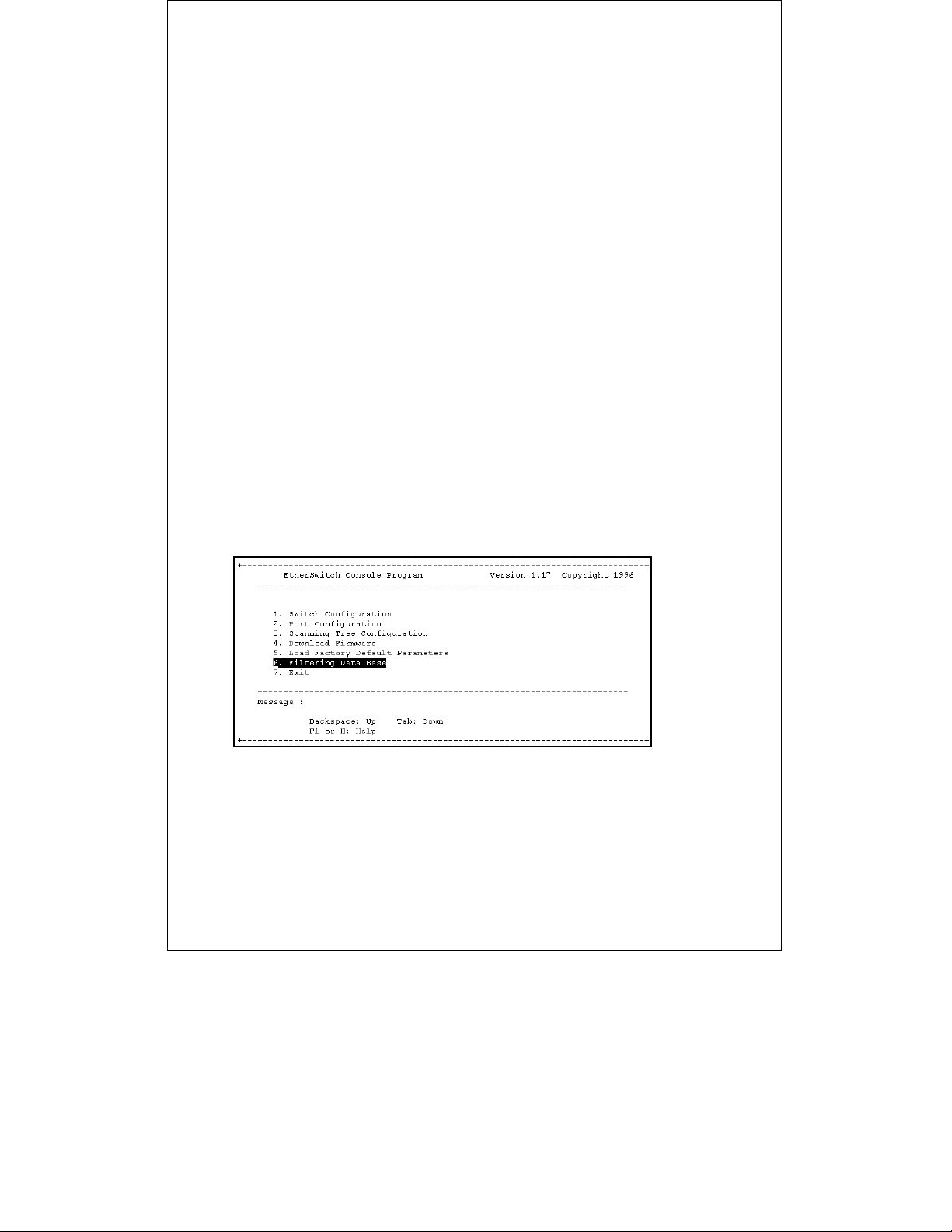
Pressing the Enter (Return) key should give you the EtherSwitch
Console Program main menu screen:
From this screen, perform the following steps to add entries to
your user defined MAC address table:
Page 4

1. Press the Tab key until you are at the “Filtering Data Base”
selection of the main menu. Press the Enter key and the
Filtering Data Base Menu appears:
2. The Tab key moves the highlighting down from field to field;
while, the Backspace key moves the highlighting up from
field to field. Also, the up and down arrow keys moves the
highlighting and cursor up and down as appropriate.
3. Move the highlighting to the Port Number field and type in
the desired port you are willing to set. Press the Tab key.
Note that the Filter State automatically changes to “Disable”
and all MAC addresses are cleared and ready for your input.
4. Move the highlighting to the Filter State field and toggle
between either “Disable, Forwarding or Blocking.” To
toggle within this field, you must use the Space bar.
5. Move the highlighting from the 1
st
MAC address field and
type in the desired MAC address, then continue this
th
procedure to the 16
MAC address field.
6. Press the F2 or S keys to save the input. Note that the
Switch must be reset in order for changes to take effect.
Page 5

Press the F4 or X keys to exit the Filtering Data Base menu
and return to the main menu.
The following represents an explanation of the selection and input
parameters for the Filtering Data Base Menu:
♦ Port Number. This selection can be set from ports 1 to 5,
and it is not required that all of the five ports of the Switch
be used in the Filtering Data Base. MAC addresses can only
be typed in for one port at a time.
♦ Filter State. This selection can be toggled (using the Space
bar) between three settings: Disable, Forwarding and
Blocking.
◊ Disable. This selection of the filter state disables the
process where forwarding or blocking is not possible. In
this setting, ALL packets will be discarded. This is the
Default for all ports in the Switch.
◊ Forwarding. This selection of the filter state enables
the forwarding process to perform forwarding of an
incoming packet. A packet with a MAC address that
matches any address in the sixteen MAC address user
defined table will be forwarded. Otherwise, the packet
will be discarded.
◊ Blocking. This selection of the filter state will compare
all incoming packets to check if it matches one of the
sixteen MAC addresses specified by the user. In the case
of a match, the packet will be discarded. Otherwise, the
packet will be forwarded.
st
MAC Address ~ 16th MAC Address. This is where
♦ 1
user defined MAC address entries can be inputted. These
entries must be accurate in order for proper management
and handling of packets. Also, it is not required that all of
the sixteen MAC addresses be used.
 Loading...