

D-Link DES-3200-28/ME, DES-3200-52P Installation Manual
xStack® DES-3200 Series Layer 2 Managed Fast Ethernet Switch Hardware Installation Guide
1

xStack® DES-3200 Series Layer 2 Managed Fast Ethernet Switch Hardware Installation Guide
i
Information in this document is subject to change without notice.
© 2012 D-Link Corporation. All rights reserved.
Reproduction in any manner whatsoever without the written permission of D-Link Corporation is strictly forbidden.
Trademarks used in this text: D-Link and the D-LINK logo are trademarks of D-Link Corporation; Microsoft and Windows are
registered trademarks of Microsoft Corporation.
Other trademarks and trade names may be used in this document to refer to either the entities claiming the marks and names or
their products. D-Link Corporation disclaims any proprietary interest in trademarks and trade names other than its own.
November, 2012 P/N 651ES32C1035G
FCC Warning
This equipment has been tested and found to comply with the limits for a Class A digital device, pursuant to Part 15 of the FCC
Rules. These limits are designed to provide reasonable protection against harmful interference when the equipme nt is operated in a
commercial environment. This equipment generates, uses, and can radiate radio frequency energy and, if not installed and used in
accordance with this manual, may cause harmful interference to radio communications. Operation of this equipment in a residential
area is likely to cause harmful interference in which case the user will be required to correct the interference at his own expense.
CE Mark Warning
This is a Class A product. In a domestic environment, this product may cause radio interference in which case the user may be
required to take adequate measures.
Warnung!
Dies ist ein Produkt der Klasse A. Im Wohnbereich kann dieses Produkt Funkstoerungen verursachen. In diesem Fall kann vom
Benutzer verlangt werden, angemessene Massnahmen zu ergreifen.
Precaución!
Este es un producto de Clase A. En un entorno doméstico, puede causar interferencias de radio, en cuyo case, puede requerirse al
usuario para que adopte las medidas adecuadas.
Attention!
Ceci est un produit de classe A. Dans un environnement domestique, ce produit pourrait causer des interférences radio, auqu el cas
l`utilisateur devrait prendre les mesures adéquates.
Attenzione!
Il presente prodotto appartiene alla classe A. Se utilizzato in ambiente domestico il prodotto può causare interferenze radio, nel cui
caso è possibile che l`utente debba assumere provvedimenti adeguati.
VCCI Warning
この装置は、クラス A 情報技術装置です。この装置を家庭環境で使用すると電波妨害を引き起こすことがあります。この場合には
使用者が適切な 対策を講ずるよう要求されることがあります。VCCI-A
BSMI
此為甲類的資訊技術設備,在居住環境中使用時,可能會造成射頻擾動,在這種情況下,使用者會被要求採取某些適當的對策。
產品 DES-3200-10-DC/DES-3200-18-DC/ DES-3200-26-DC/ DES-3200-52DC 須連接額定電流 2A 至 10A 之斷路器,做為與直流電源
之切斷裝置。
SFP (Mini-GBIC), XENPAK, and XFP Regulatory Compliance
Networks pluggable optical modules meet the following regulatory requirements:
Class 1 Laser Product
EN60825-1+A2:2001 or later, European laser standard
FCC 21 CFR Chapter 1, Subchapter J in accordance with FDA & CDRH requirements

xStack® DES-3200 Series Layer 2 Managed Fast Ethernet Switch Hardware Installation Guide
Table of Contents
Intended Readers ...................................................................................................................................................iii
Typographical Conventions......................................................................................................................................................iii
Notes, Notices, and Cautions...................................................................................................................................................iii
Safety Instructions ...................................................................................................................................................................iii
Safety Cautions........................................................................................................................................................................iv
General Precautions for Rack-Mountable Products..................................................................................................................v
Protecting Against Electrostatic Discharge ...............................................................................................................................v
Chapter 1 Introduction ...........................................................................................................................................1
Switch Description ...................................................................................................................................................................1
Front Panel Description ........................................................................................................................................................... 2
LED Indicators.......................................................................................................................................................................6
Rear Panel Description.......................................................................................................................................................... 11
Side Panel Description........................................................................................................................................................... 13
Gigabit Combo Ports.............................................................................................................................................................. 16
Chapter 2 Installation ...........................................................................................................................................18
Package Contents.................................................................................................................................................................. 18
Before You Connect to the Network....................................................................................................................................... 18
Installing the Switch without the Rack.................................................................................................................................... 19
Installing the Switch in a Rack ...............................................................................................................................................19
Mounting the Switch in a Standard 19" Rack......................................................................................................................... 20
Power on AC Power............................................................................................................................................................... 20
Power Failure...................................................................................................................................................................... 20
Connecting DC Power ........................................................................................................................................................... 20
Alarm Connector (DES_3200-28/ME only) ............................................................................................................................ 21
Chapter 3 Connecting the Switch .......................................................................................................................23
Switch to End Node ............................................................................................................................................................... 23
Switch to Hub or Switch......................................................................................................................................................... 24
Chapter 4 Introduction to Switch Management ................................................................................................. 25
Management Options............................................................................................................................................................. 25
Web-based Management Interface........................................................................................................................................ 25
SNMP-Based Management ................................................................................................................................................... 25
Connecting the Console Port................................................................................................................................................. 25
First Time Connecting to the Switch ...................................................................................................................................... 26
Password Protection.............................................................................................................................................................. 27
SNMP Settings....................................................................................................................................................................... 28
Traps................................................................................................................................................................................... 28
MIBs.................................................................................................................................................................................... 28
IP Address Assignment.......................................................................................................................................................... 29
Chapter 5 Web-based Switch Configuration...................................................................................................... 31
Introduction............................................................................................................................................................................ 31
Login to Web Manager........................................................................................................................................................... 31
Web-based User Interface..................................................................................................................................................... 32
Areas of the User Interface................................................................................................................................................. 32
Web Pages ............................................................................................................................................................................ 33
Appendix A – Technical Specifications .............................................................................................................. 34
Appendix B – Cables and Connectors................................................................................................................ 40
Ethernet Cable....................................................................................................................................................................... 40
Console Cable ....................................................................................................................................................................... 41
Appendix C – Module Specs and Cable Lengths............................................................................................... 42
Warranty & Technical Support.............................................................................................................................43
ii
xStack® DES-3200 Series Layer 2 Managed Fast Ethernet Switch Hardware Installation Guide
Intended Readers
Typographical Conventions
Notes, Notices, and Cautions
Safety Instructions
Safety Cautions
General Precautions for Rack-Mountable Products
Protecting Against Electrostatic Discharge
The DES-320
0 Series Har
dware Installation Guide contains detailed information about the hardware specifications
of a Switch in this series. It also contains brief information on how to configure and manage a Switch in this series.
This manual is intended for advanced level users that are familiar with network management concepts and
terminology. For all practical reasons all the Switches in this series will simply be referred to as the Switch throughout
this manual. All example screenshots are taken from the DES-3200-28P Switch.
Typographical Conventions
Convention Description
[ ]
In a command line, square brackets indicate an optional entry. For example: [copy filename]
means that optionally you can type copy followed by the name of the file. Do not type the
brackets.
Bold font
Indicates a button, a toolbar icon, menu, or menu item. For example: Open the File menu
and choose Cancel. Used for emphasis. May also indicate system messages or prompts
appearing on your screen. For example: You have mail. Bold font is also used to represent
filenames, program names and commands. For example: use the copy command.
Boldface
Typewriter Font
Indicates commands and responses to prompts that must be typed exactly as printed in the
manual.
Initial capital letter
Indicates a window name. Names of keys on the keyboard have initial capitals. For example:
Click Enter.
Italics
Indicates a window name or a field. Also can indicate a variables or parameter that is
replaced with an appropriate word or string. For example: type filename means that you
should type the actual filename instead of the word shown in italic.
Menu Name > Menu
Option
Menu Name > Menu Option Indicates the menu structure. Device > Port > Port
Properties means the Port Properties menu option under the Port menu option that is
located under the Device menu.
Notes, Notices, and Cautions
A NOTE indicates important information that helps you make better use of your device.
A NOTICE indicates either potential damage to hardware or loss of data and tells you how to avoid
the problem.
A CAUTION indicates a potential for property damage, personal injury, or death.
Safety Instructions
Use the following safety guidelines to ensure your own personal safety and to help protect your system from potential
damage. Throughout this document, the caution icon (
) is used to indicate cautions and precautions that you need
to review and follow.
iii

xStack® DES-3200 Series Layer 2 Managed Fast Ethernet Switch Hardware Installation Guide
Safety Cautions
To reduce the risk of bodily injury, electrical shock, fire, or damage to the equipment, observe the following
precautions.
Observe and follow service markings.
o Do not service any product except as explained in your system documentation.
o Opening or removing cove rs that are marked with the triangular symbol with a lightning bolt may expose
you to electrical shock.
o Only a trained service technician should service components inside these compartments.
If any of the following conditions occur, unplug the product from the electrical outlet and replace the part or
contact your trained service provider:
o The power cable, extension cable, or plug is damaged.
o An object has fallen into the product.
o The product has been exposed to water.
o The product has been dro pped or damaged.
o The product does not operate correctly whe n you follow the operating instructions.
Keep your system away from radiators and heat sources. Also, do not block cooling vents.
Do not spill food or liquids on your system components, and never operate the product in a wet environment. If
the system gets wet, see the appropriate section in your troubleshooting guide or contact your trained service
provider.
Do not push any objects into the openings of your system. Doing so can cause fire or electric shock by shorting
out interior components.
Use the product only with approved equipment.
Allow the product to cool before removing covers or touching internal components.
Operate the product only from the type of external power source indicated on the electrical ratings label. If you
are not sure of the type of power source required, consult your service provider or local power company.
To help avoid damaging your system, be sure the voltage on the power supply is set to match the power
available at your location:
o 115 volts (V)/60 hertz (Hz) in most of North and South America and some Far Eastern countries such as
South Korea and Taiwan
o 100 V/50 Hz in eastern Japan and 100 V/60 Hz in western Japan
o 230 V/50 Hz in most of Europe, the Middle East, and the Far East
Also, be sure that attached devices are electrically rated to operate with the power available in your location.
Use only approved power cable(s). If you have not been provided with a power cable for your system or for any
AC-powered option intended for your system, purchase a power cable that is approved for use in your co untry.
The power cable must be rated for the product and for the voltage and current marked on the product's
electrical ratings label. The voltage and current rating of the cable should be greater than the ratings marked on
the product.
To help prevent electric shock, plug the system and peripheral power cables into properly grounded electrical
outlets. These cables are equipped with three-prong plugs to help ensure proper grounding. Do not use adapter
plugs or remove the grounding prong from a cable. If you must use an extension cable, use a 3-wire cable with
properly grounded plugs.
Observe extension cable and power strip ratings. Make sure that the total ampere rating of all products plugged
into the extension cable or power strip does not exceed 80 percent of the ampere ratings limit for the extension
cable or power strip.
To help protect your system from sudden, transient increases and decreases in electrical power, use a surge
suppressor, line conditioner, or uninterruptible power supply (UPS).
Position system cables and power cables carefully; route cables so that they cannot be stepped on or tripped
over. Be sure that nothing rests on any cables.
Do not modif
y power cables or plugs. Consult a licensed electrician or your power company for site
modifications. Always follow your local/national wiring rules.
When connecting or disconnecting power to hot-pluggable power supplies, if offered with you r system, ob serve
the following guidelines:
o Install the power supply before connecting the power cable to the power supply.
o Unplug the power ca ble before removing the power supply.
iv
xStack® DES-3200 Series Layer 2 Managed Fast Ethernet Switch Hardware Installation Guide
o If the system has multipl
e sources of power, disconnect power from the system by unplugging all power
cables from the power supplies.
Move products with care; ensure that all casters and/or stabilizers are firmly connected to the system. Avoid
sudden stops and uneven surfaces.
General Precautions for Rack-Mountable Products
Observe the following precautions for rack stability and safety. Also, refer to the rack installation documentation
accompanying the system and the rack for specific caution statements and procedures.
Systems are considered to be components in a rack. Thus, "component" refers to any system as well as to
various peripherals or supporting hardware.
Before working on the rack, make sure that the stabilizers are secured to the rack, extended to the floor, and
that the full weight of the rack rests on the floor. Install front and side stabilizers on a single rack or front
stabilizers for joined multiple racks before working on the rack.
Always load the rack from the bottom up, and load the heaviest item in the rack first.
Make sure that the rack is level and stable before extending a component from the rack.
Use caution when pressing the component rail release latches and sliding a component into or out of a rack;
the slide rails can pinch your fingers.
After a component is inserted into the rack, carefully extend the rail into a locking position, and then slide the
component into the rack.
Do not overload the AC supply branch circuit that provides power to the rack. The total rack load should not
exceed 80 percent of the branch circuit rating.
Ensure that proper airflow is provided to components in the rack.
Do not step on or stand on any component when servicing other components in a rack.
NOTE: A qualified electrician must perform all connections to DC power and to safety grounds. All
electrical wiring must comply with applicable local, regional or national codes and pra ctices.
CAUTION: Never defeat the ground conductor or operate the equipment in the absence of a suitably
installed ground conductor. Contact the appropriate electrical inspection authority or an electrician if
you are uncertain that suitable grounding is available.
CAUTION: The system chassis must be positively grounded to the rack cabinet frame. Do not
attempt to connect power to the system until grounding cables are connected. A qualified electrical
inspector must inspect completed power and safety ground wiring. An energy hazard will exist if the
safety ground cable is omitted or disconnected.
CAUTION: Do not replace the battery with an incorrect type. The risk of explosion exists if the
replacement battery is not the correct lithium battery type. Dispose of used batteries according to the
instructions.
Protecting Against Electrostatic Discharge
Static electricity can harm delicate components inside your system. To prevent static damage, discharge static
electricity from your body before you touch any of the electronic components, such as the microprocessor. You can do
so by periodically touching an unpainted metal surface on the chassis.
You can also take the following steps to prevent damage from electrostatic discharge (ESD):
1. When unpacking a static-sensitive component from its shipping carton, do not remove the component from the
antistatic packing material until you are ready to install the component in your system. Just before unwrapping
the antistatic packaging, be sure to discharge static electricity from your body.
2. When transporting a sensitive compon ent, first place it in an antistatic container or packaging.
3. Handle all sensitive components in a static-safe area. If possible, use antistatic floor pads, workbench pads and
an antistatic grounding strap.
v

xStack® DES-3200 Series Layer 2 Ethernet Managed Switch Hardware Installation Guide
1
Chapter 1 Introduction
Switch Description
Front Panel Description
Rear Panel Description
Side Panel Description
Gigabit Combo Ports
Switch Description
The DES-3200 Series Hardware Installation Guide describes the hardware installation and specifications
concerning the DES-3200 Series switches. These switches are identical in configuration and very similar in basic
hardware and consequentially, most of the information in this manual will be universal to the total group of switches.
This manual concentrates on the Hardware Version C1.
The DES-3200 Series switches are equipped with Copper ports (10/100Mbps) and SFP ports (100/1000Mbps) that
can be used to attach various networking devices to the network like Computers, Notebooks, Print Servers, Network
Attached Storage devices, IP Cameras, VoIP PBX devices, and other Switches. The Small Form Factor Portable (SFP)
combo ports can be used together with fiber-optical transceivers in order to connect various ot her networking devices,
using a fiber-optic connection, to the network at Gigabit Ethernet speeds over great distances.
The DES-3200 Series switches provide unsurpassed performance, fault tolerance, scalable flexibility, robust security,
standard-based interoperability and impressive technology to future-proof departmental and enterprise network
deployments with an easy migration path.
The Series features the following list of switches:
Switch Description
DES-3200-10
Eight 10/100Mbps Copper Ports, One 100/1000Mbps SFP Port, One Combo
10/100/1000Mbps Copper / 100/1000Mbps SFP Port, and One RJ-45 Console Port for
out-of-band CLI configuration.
DES-3200-10-DC
Eight 10/100Mbps Copper Ports, One 100/1000Mbps SFP Port, One Combo
10/100/1000Mbps Copper / 100/1000Mbps SFP Port, and One RJ-45 Console Port for
out-of-band CLI configuration.
DES-3200-18
Sixteen 10/100Mbps Copper Ports, One 100/1000Mbps SFP Port, One Combo
10/100/1000Mbps Copper / 100/1000Mbps SFP Port, and One RJ-45 Console Port for
out-of-band CLI configuration.
DES-3200-18-DC
Sixteen 10/100Mbps Copper Ports, One 100/1000Mbps SFP Port, One Combo
10/100/1000Mbps Copper / 100/1000Mbps SFP Port, and One RJ-45 Console Port for
out-of-band CLI configuration.
DES-3200-26
Twenty-four 10/100Mbps Copper Ports, Two Combo 10/100/1000Mbps Copper /
100/1000Mbps SFP Ports, and One RJ-45 Console Port for out-of-band CLI
configuration.
DES-3200-26-DC
Twenty-four 10/100Mbps Copper Ports, Two Combo 10/100/1000Mbps Copper /
100/1000Mbps SFP Ports, and One RJ-45 Console Port for out-of-band CLI
configuration.
DES-3200-28
Twenty-four 10/100Mbps Copper Ports, Two Combo 10/100/1000Mbps Copper /
100/1000Mbps SFP Ports, Two 100/1000Mbps SFP Ports, and One RJ-45 Console
Port for out-of-band CLI configuration.
DES-3200-28F
Twenty-four 100Mbps SFP Ports, Four Combo 10/100/1000Mbps Copper /
100/1000Mbps SFP Ports, and One RJ-45 Console Port for out-of-band CLI
configuration.
DES-3200-28P
Twenty-four 10/100Mbps Power over Ethernet Copper Ports, Two Combo
xStack® DES-3200 Series Layer 2 Ethernet Managed Switch Hardware Installation Guide
10/100/1000
Mbps Copper / 100/1000Mbps SFP Ports, Two 10/100/1000Mbps Copper
Ports, and One RJ-45 Console Port for out-of-band CLI configuration.
DES-3200-28/ME
Twenty-four 10/100Mbps Copper Ports, Two Combo 10/100/1000Mbps Copper /
100/1000Mbps SFP Ports, Two 100/1000Mbps SFP Ports, One RJ-45 Console Port for
out-of-band CLI configuration, and One Alarm Connector Port.
DES-3200-52
Forty-eight 10/100Mbps Copper Ports, Two Combo 10/100/1000Mbps Copper /
100/1000Mbps SFP Ports, Two 100/1000Mbps SFP Ports, and One RJ-45 Console
Port for out-of-band CLI configuration.
DES-3200-52-DC
Forty-eight 10/100Mbps Copper Ports, Two Combo 10/100/1000Mbps Copper /
100/1000Mbps SFP Ports, Two 100/1000Mbps SFP Ports, and One RJ-45 Console
Port for out-of-band CLI configuration.
DES-3200-52P
Forty-eight 10/100Mbps Power over Ethernet Copper Ports, Two Combo
10/100/1000Mbps Copper / 100/1000Mbps SFP Ports, Two 10/100/1000Mbps Copper
Ports, and One RJ-45 Console Port for out-of-band CLI configuration.
These switches have a combination of 1000BASE-T ports and SFP ports that may be used in to uplink various
network devices to the Switch, including PCs, hubs and other switches to provide a gigabit Ethernet uplink in fullduplex mode. The SFP (Small Form Factor Portable) combo ports are used with fiber-optical transceiver ca bling in
order to uplink various other networking devices for a gigabit link that may span great distances.
Front Panel Description
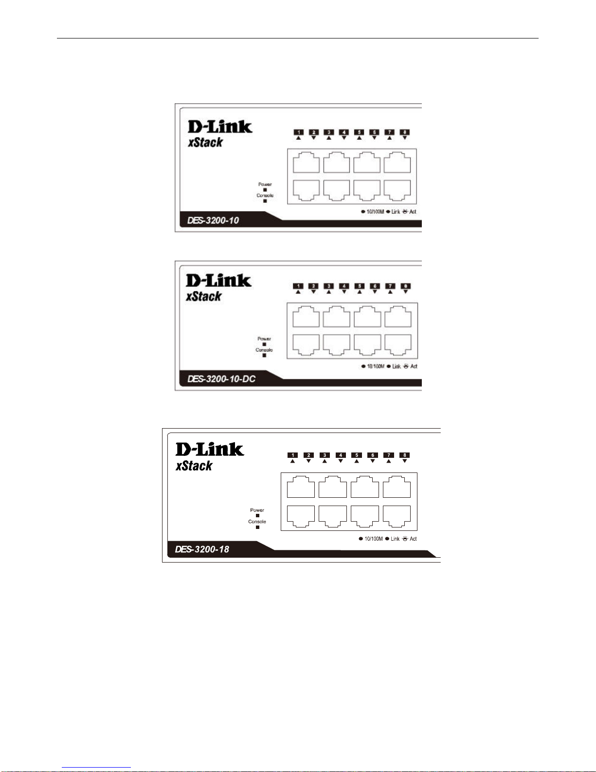
The front panel of the DES-3200-10 switch consists out of the following:
Eight 10/100Mbps Copper Ports
One Combo 10/100/1000Mbps Copper / 100/1000Mbps SFP port
One 100/1000Mbps SFP Port
One RJ-45 Console Port
LEDs for Power, Console, Link/Act for port 1 to 8, and Link/Act/Speed for port 9 and 10
Figure 1-1. Front Panel of the DES-3200-10
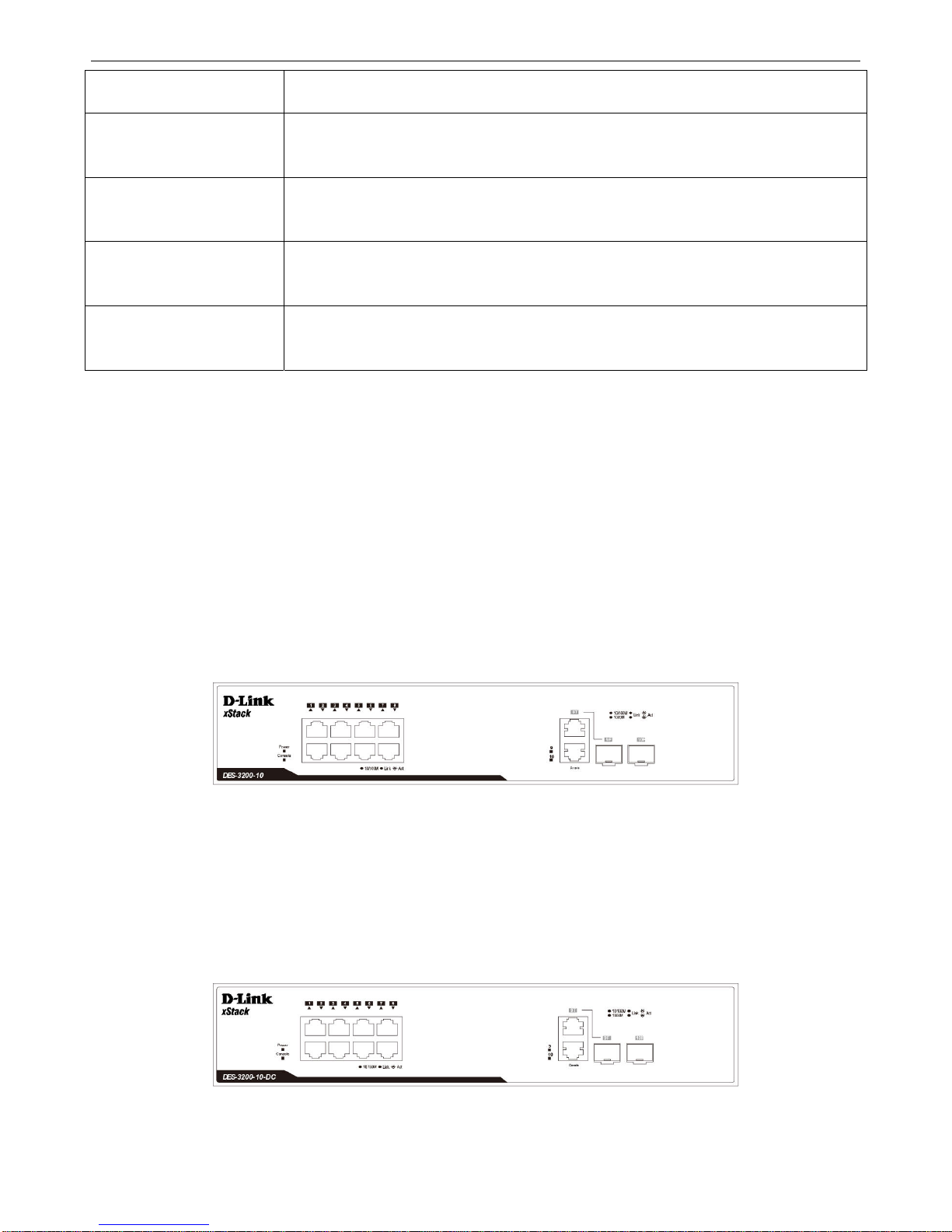
The front panel of the DES-3200-10-DC switch consists out of the following:
Eight 10/100Mbps Copper Ports
One Combo 10/100/1000Mbps Copper / 100/1000Mbps SFP port
One 100/1000Mbps SFP Port
One RJ-45 Console Port
LEDs for Power, Console, Link/Act for port 1 to 8, and Link/Act/Speed for port 9 and 10
Figure 1-2. Front Panel of the DES-3200-10-DC
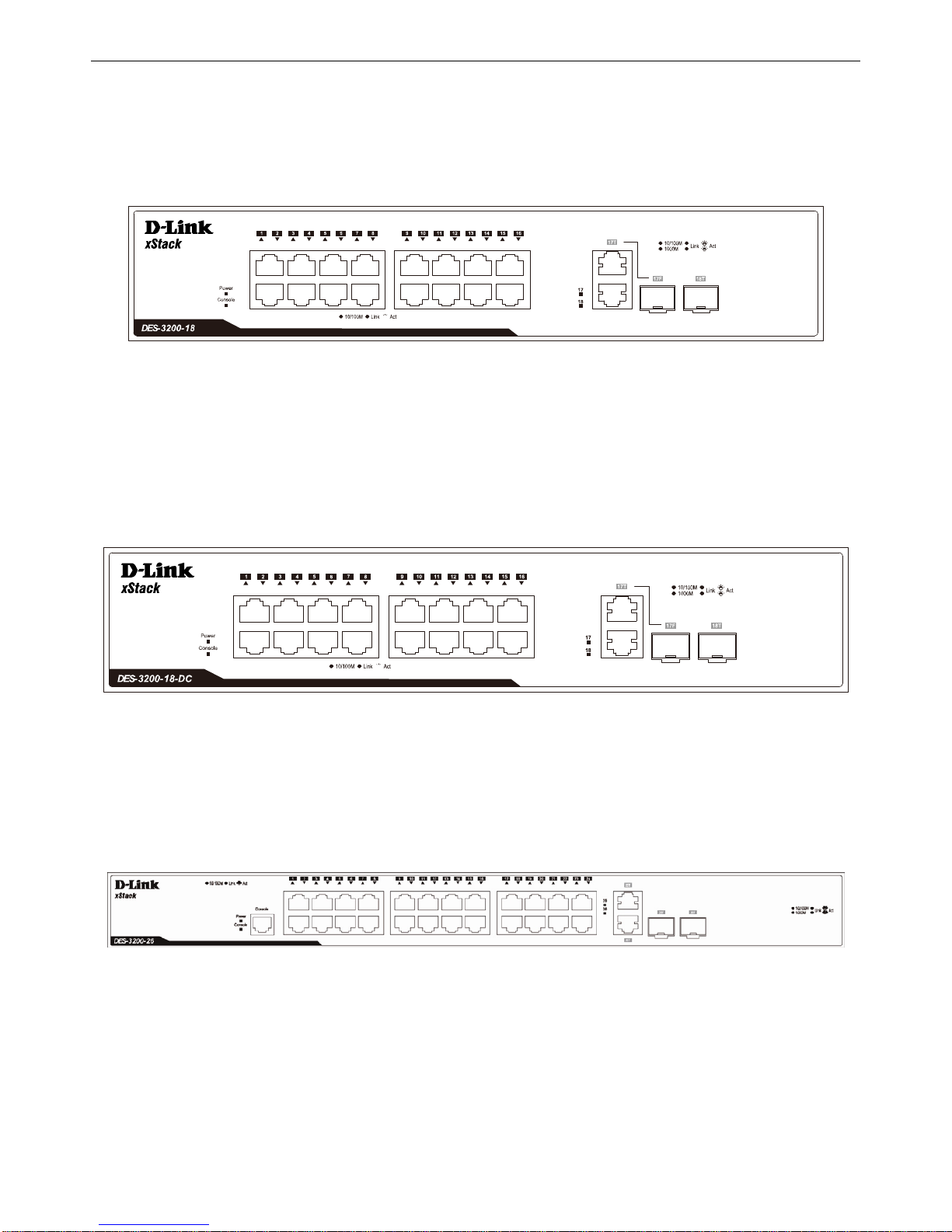
The front panel of the DES-3200-18 switch consists out of the following:
2
xStack® DES-3200 Series Layer 2 Ethernet Managed Switch Hardware Installation Guide
Sixteen 10/10
0Mbps Copper Ports
One Combo 10/100/1000Mbps Copper / 100/1000Mbps SFP port
One 100/1000Mbps SFP Port
One RJ-45 Console Port
LEDs for Power, Console, Link/Act for port 1 to 16, and Link/Act/Speed for port 17 and 18
Figure 1-3. Front Panel of the DES-3200-18
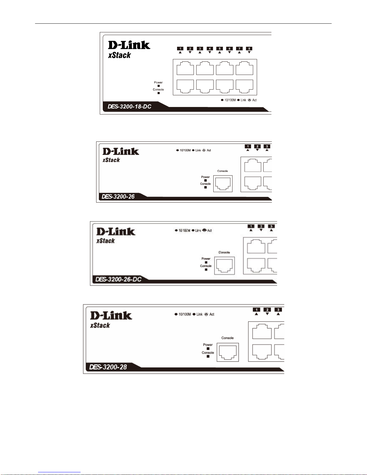
The front panel of the DES-3200-18-DC switch consists out of the following:
Sixteen 10/100Mbps Copper Ports
One Combo 10/100/1000Mbps Copper / 100/1000Mbps SFP port
One 100/1000Mbps SFP Port
One RJ-45 Console Port
LEDs for Power, Console, Link/Act for port 1 to 16, and Link/Act/Speed for port 17 and 18
Figure 1-4. Front Panel of the DES-3200-18-DC
The front panel of the DES-3200-26 switch consists out of the following:
Twenty-four 10/100Mbps Copper Ports
Two Combo 10/100/1000Mbps Copper / 100/1000Mbps SFP ports
One RJ-45 Console Port
LEDs for Power, Console, Link/Act for port 1 to 24, and Link/Act/Speed for port 25 and 26
Figure 1-5. Front Panel of the DES-3200-26
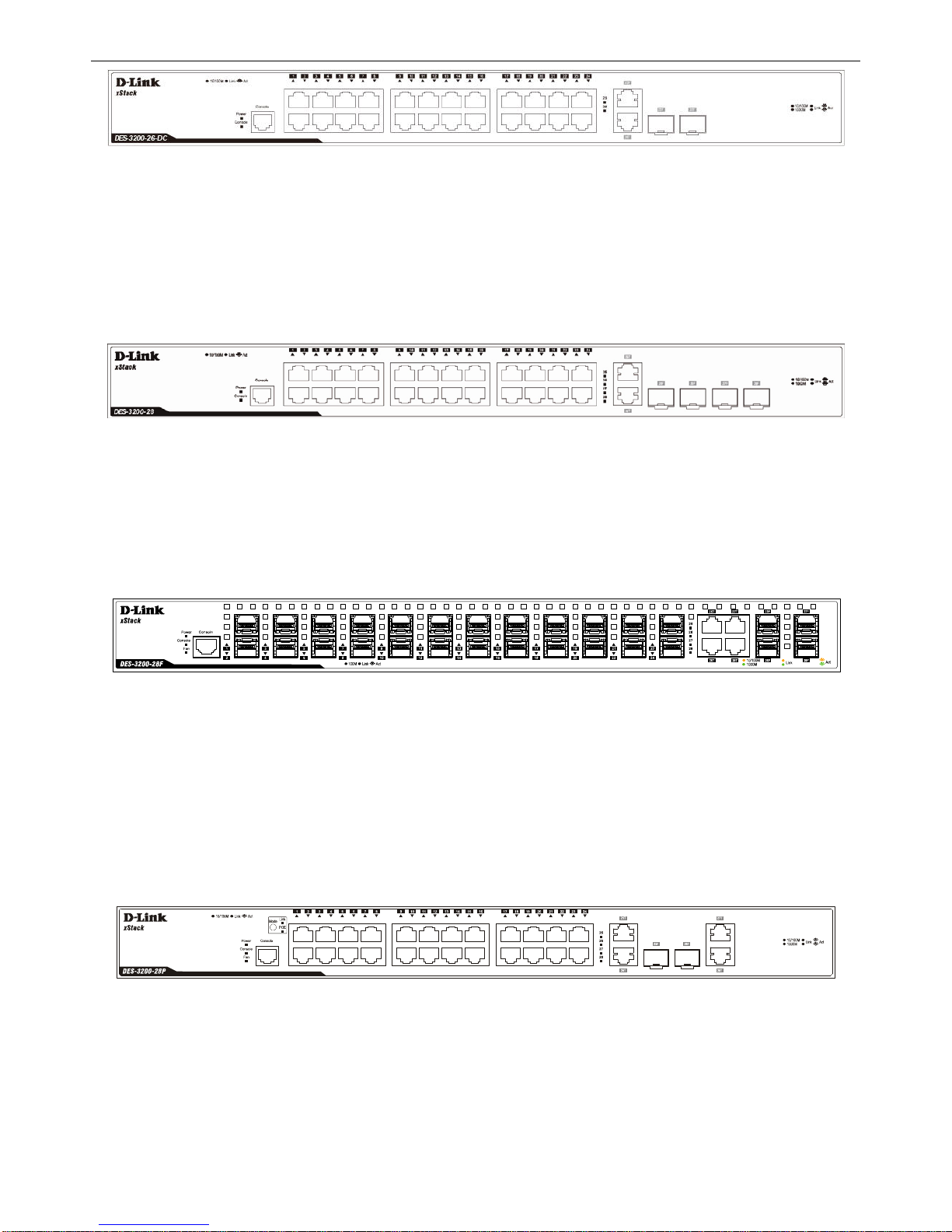
The front panel of the DES-3200-26-DC switch consists out of the following:
Twenty-four 10/100Mbps Copper Ports
Two Combo 10/100/1000Mbps Copper / 100/1000Mbps SFP ports
One RJ-45 Console Port
LEDs for Power, Console, Link/Act for port 1 to 24, and Link/Act/Speed for port 25 and 26
3
xStack® DES-3200 Series Layer 2 Ethernet Managed Switch Hardware Installation Guide
Figure 1-6. Front Panel of the DES-3200-26-DC
The front panel of the DES-3200-28 switch consists out of the following:
Twenty-four 10/100Mbps Copper Ports
Two Combo 10/100/1000Mbps Copper / 100/1000Mbps SFP ports
Two 100/1000Mbps SFP Ports
One RJ-45 Console Port
LEDs for Power, Console, Link/Act for port 1 to 24, and Link/Act/Speed for port 25 to 28
Figure 1-7. Front Panel of the DES-3200-28
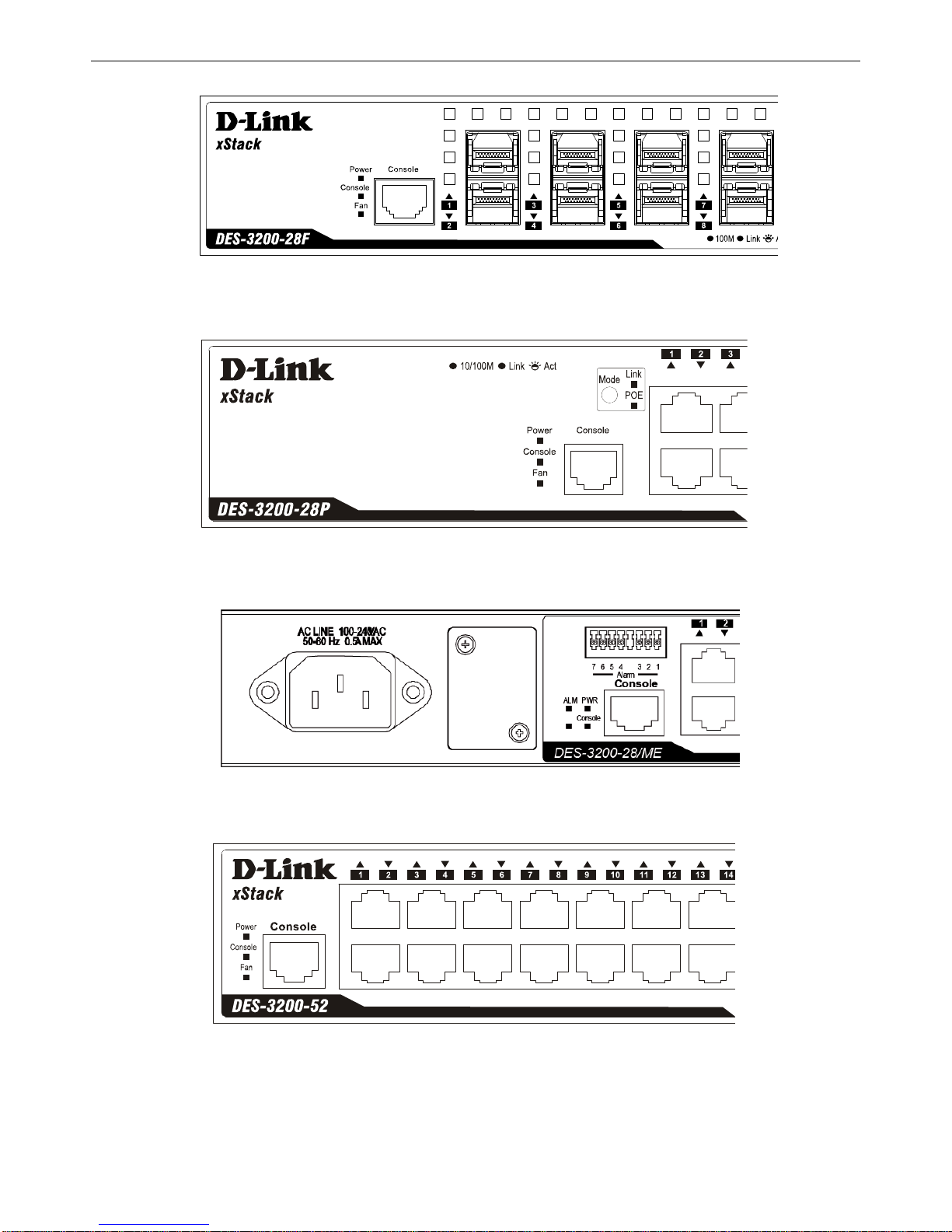
The front panel of the DES-3200-28F switch consists out of the following:
Twenty-four 100Mbps SFP Ports
Four Combo 10/100/1000Mbps Copper / 100/1000Mbps SFP Ports
One RJ-45 Console Port
LEDs for Power, Console, Fan, Link/Act for port 1 to 24, and Link/Act/Speed for port 25 to 28
Figure 1-8. Front Panel of the DES-3200-28F
The front panel of the DES-3200-28P switch consists out of the following:
Twenty-four 10/100Mbps Power over Ethernet Copper Ports
Two Combo 10/100/1000Mbps Copper / 100/1000Mbps SFP ports
Two 10/100/1000Mbps Copper Ports
One RJ-45 Console Port
Link/PoE button
LEDs for Link, PoE, Power, Console, Fan, Link/Act for port 1 to 24, and Link/Act/Speed for port 25 to 28
Figure 1-9. Front Panel of the DES-3200-28P
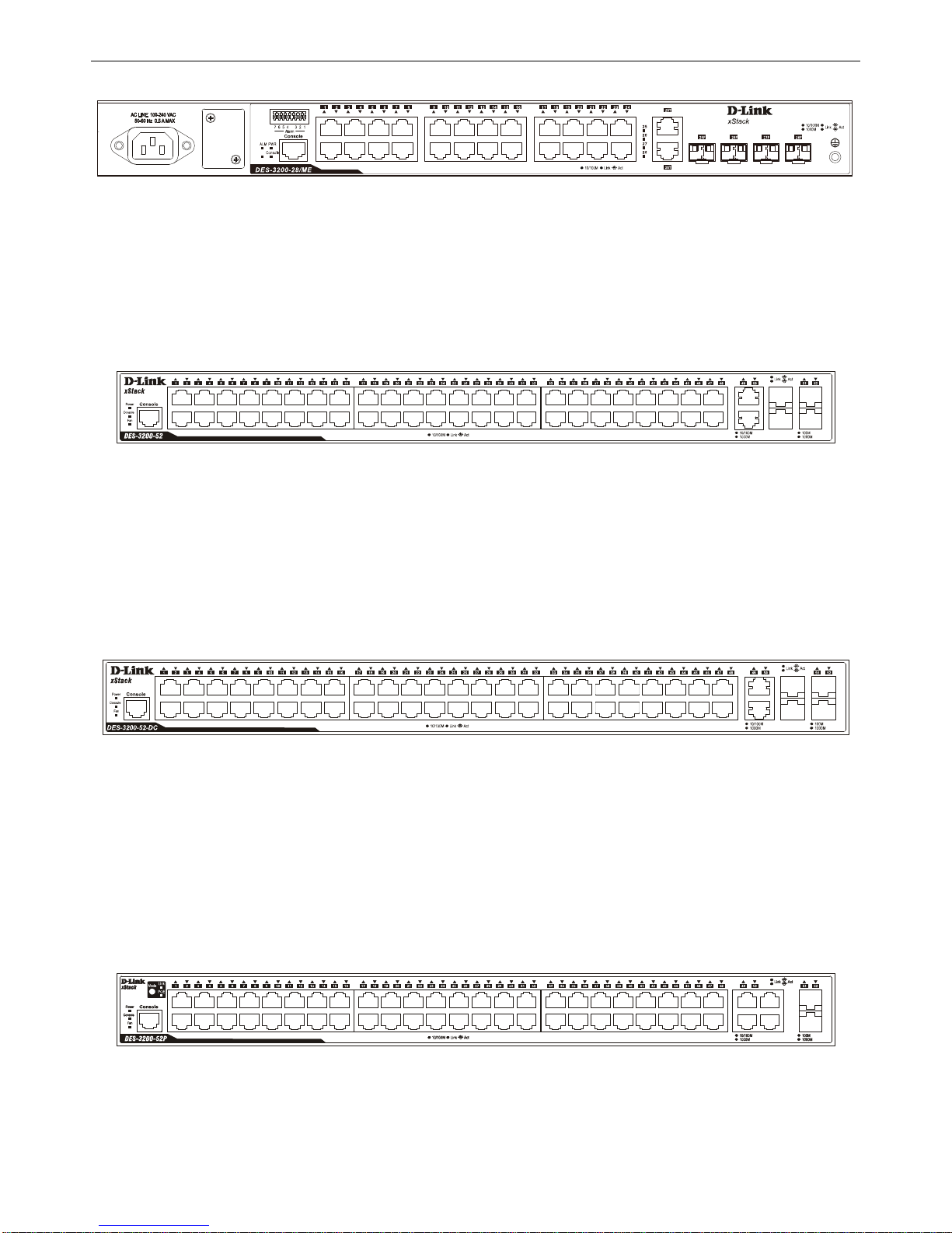
The front panel of the DES-3200-28/ME switch consists out of the following:
Twenty-four 10/100Mbps Copper ports
Two Combo 10/100/1000Mbps Copper 100/1000Mbps SFP ports, Two 100/1000Mbps SFP ports
One RJ-45 Console port
One Alarm Connector
LEDs for Power, Console, Alarm, and Link/Act/Speed for each port
4
xStack® DES-3200 Series Layer 2 Ethernet Managed Switch Hardware Installation Guide
Figure 1-10. Front Panel of the DES-3200-28/ME
The front panel of the DES-3200-52 switch consists out of the following:
Forty-eight 10/100Mbps Copper Ports
Two Combo 10/100/1000Mbps Copper / 100/1000Mbps SFP ports
Two 100/1000Mbps SFP Ports
One RJ-45 Console Port
LEDs for Power, Console, Fan, Link/Act for port 1 to 48, and Link/Act/Speed for port 49 to 52
Figure 1-11. Front Panel of the DES-3200-52
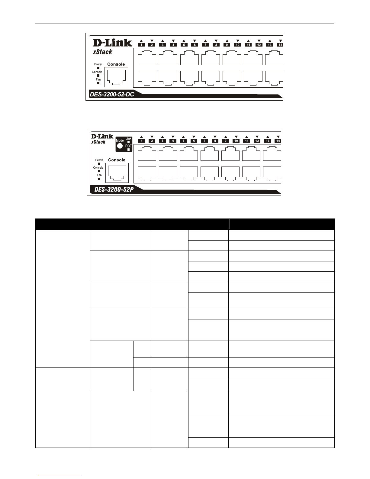
The front panel of the DES-3200-52-DC switch consists out of the following:
Forty-eight 10/100Mbps Copper Ports
Two Combo 10/100/1000Mbps Copper / 100/1000Mbps SFP Ports
Two 100/1000Mbps SFP Ports
One RJ-45 Console Port
LEDs for Power, Console, Fan, Link/Act for port 1 to 48, and Link/Act/Speed for port 49 to 52
Figure 1-12. Front Panel of the DES-3200-52-DC
The front panel of the DES-3200-52P switch consists out of the following:
Forty-eight 10/100Mbps Power over Ethernet Copper Ports
Two Combo 10/100/1000Mbps Copper / 100/1000Mbps SFP ports
Two 10/100/1000Mbps Copper Ports
Link/PoE button
One RJ-45 Console Port
LEDs for Link, PoE, Power, Console, Fan, Link/Act for port 1 to 48, and Link/Act/Speed for port 49 to 52
Figure 1-13. Front Panel of the DES-3200-52P
5
xStack® DES-3200 Series Layer 2 Ethernet Managed Switch Hardware Installation Guide
LED Indicators
The Switch supports LED indicators for Power, Console, Fan, and Link/Act or Link/Act/Speed for each port. The
following shows the LED indicators for the DES-3200 Series along with an explanation of each indicator.
Figure 1-14. LED Indicators on DES-3200-10
Figure 1-15. LED Indicators on DES-3200-10-DC
Figure 1-16. LED Indicators on DES-3200-18
6
xStack® DES-3200 Series Layer 2 Ethernet Managed Switch Hardware Installation Guide
Figure 1-17. LED Indicators on DES-3200-18-DC
Figure 1-18. LED Indicators on DES-3200-26
Figure 1-19 LED Indicators on DES-3200-26-DC
Figure 1-20. LED Indicators on DES-3200-28
7
xStack® DES-3200 Series Layer 2 Ethernet Managed Switch Hardware Installation Guide
Figure 1-21. LED Indicators on DES-3200-28F
Figure 1-22. LED Indicators on DES-3200-28P
Figure 1-23. LED Indicators on DES-3200-28/ME
Figure 1-24. LED Indicators on DES-3200-52
8
xStack® DES-3200 Series Layer 2 Ethernet Managed Switch Hardware Installation Guide
Figure 1-25. LED Indicators on DES-3200-52-DC
Figure 1-26. LED Indicators on DES-3200-52P
Location LED Indicative Color Status Description
Solid Light Power on.
Power
Green
Light off Power off.
Solid Light Console on.
Blinking POST is in progress.
Console
Green
Light off Console off.
Solid Light Attached device failure is detected.
Alarm (DES-320028/ME only)
Red
Light off
Attached device is off or functioning
properly.
Blinking Light When any of the fans has failed.
Fan
(DES-3200-
28F/28P/52/52-DC/52P
only)
Red
Light off When all fans work no rmally.
Link
Green Solid Light
When 10/100Mbps port is in Link/Act
Mode.
Per Device
Port LED Mode
(DES-3200-
28P/52P only)
POE
Green Solid Light When 10/100Mbps port is in PoE Mode.
Solid Light RPS in use
RPS (Only for
Redundant
Power)
Green
Light off RPS not in use
Solid Green
When there is a secure 10/100Mbps
Ethernet connection (or link) at any of the
ports.
Blinking Green
When there is reception or transmission
(i.e. Activity—Act) of data occurring at a
10/100Mbps Ethernet connected port.
LED Per
10/100Mbps
Copper Port
Link/Act
Green
Light off No link.
9

xStack® DES-3200 Series Layer 2 Ethernet Managed Switch Hardware Installation Guide
10
Solid Green When there is a secure 1000Mbps
Ethernet connection (or link) at any of the
ports.
Blinking Green When there is reception or transmission
(i.e. Activity—Act) of data occurring at a
1000Mbps Ethernet connected port.
Solid Amber When there is a secure 10/100Mbp s
Ethernet connection (or link) at any of the
ports.
Blinking Amber When there is reception or transmission
(i.e. Activity—Act) of data occurring at a
10/100Mbps Ethernet connected port.
LED Per
10/100/1000Mbps
Copper Port
Link/Act/Speed
Green/Amber
Light off No link.
Solid Green Power feeding.
Blinking Green Error Condition
LED Per
10/100Mbps Port in
PoE Mode (DES3200-28P/52P only)
PoE
Green
Light off No powe r feeding.
Solid Green When there is a secure 100Mbps
Ethernet connection (or link) at any of the
ports.
Blinking Green When there is reception or transmission
(i.e. Activity—Act) of data occurring at a
100Mbps Ethernet connected port.
LED Per 100Mbps
SFP Port (DES3200-28F only)
Link/Act
Green
Light off No link.
Solid Green When there is a secure 1000Mbps
Ethernet connection (or link) at any of the
ports.
Blinking Green When there is reception or transmission
(i.e. Activity—Act) of data occurring at a
1000Mbps Ethernet connected port.
Solid Amber When there is a secure 100Mbp s
Ethernet connection (or link) at any of the
ports.
Blinking Amber When there is reception or transmission
(i.e. Activity—Act) of data occurring at a
100Mbps Ethernet connected port.
LED Per
100/1000Mbps SFP
Port
Link/Act/Speed
Green/Amber
Light off No link.
xStack® DES-3200 Series Layer 2 Ethernet Managed Switch Hardware Installation Guide
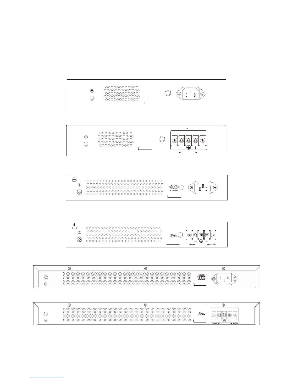
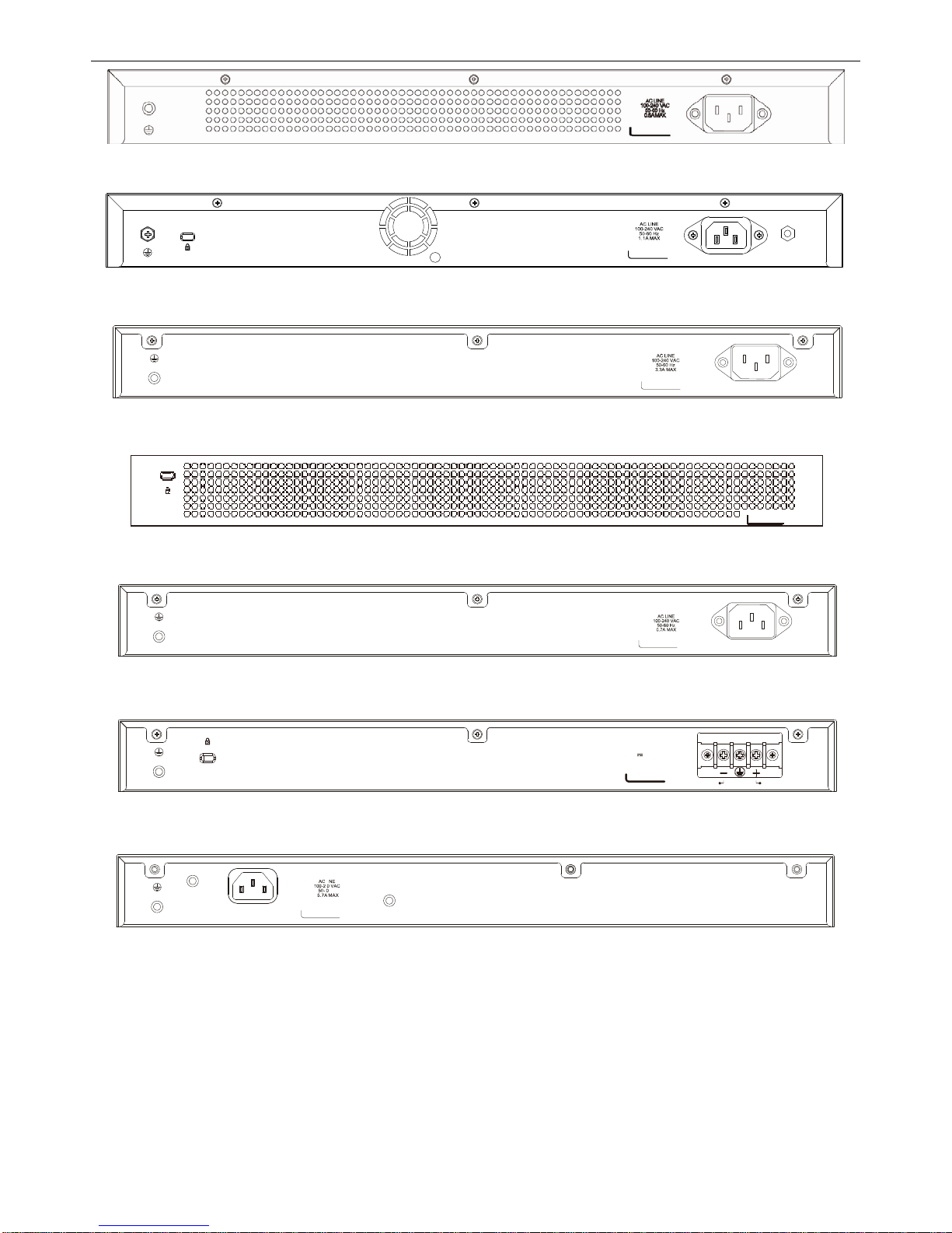
Rear Panel Description
The rear panel of the Switch contains an AC or DC power connector. The AC powe r connector is a standard threepronged connector that supports the power cord. Plug-in the female connector of the provided power cord into this
socket, and the male side of the cord into a power outlet. The Switch automatically adjusts its power setting to any
supply voltage in the range from 100 to 240 VAC at 50 to 60 Hz. The DC power supply has a three-terminal wiring
block consisting of a positive (+), a negative (-) and a safety ground terminal. Connect the Kensington-c ompatible
security lock, at the rear of the switch, to a secure immovable device. Insert the lock into the notch and turn the key to
secure the lock.
ACLINE
100-240 VAC
50-60Hz
0.
3AMAX
Figure 1-27. Rear panel view of the DES-3200-10
0.4A MA X
-48V -48V RET
-48 V
Figure 1-28. Rear panel view of the DES-3200-10-DC
Figure 1-29. Rear panel view of the DES-3200-18
Figure 1-30. Rear panel view of the DES-3200-18-DC
Figure 1-31. Rear panel view of the DES-3200-26
Figure 1-32. Rear panel view of the DES-3200-26-DC
11
xStack® DES-3200 Series Layer 2 Ethernet Managed Switch Hardware Installation Guide
Figure 1-33. Rear panel view of the DES-3200-28
Figure 1-34. Rear panel view of the DES-3200-28F
Figure 1-35. Rear panel view of the DES-3200-28P
Figure 1-36. Rear panel view of the DES-3200-28/ME
Figure 1-37. Rear panel view of the DES-3200-52
-48V -48VRET
-48V 1.1AMAX
Figure 1-38. Rear panel view of the DES-3200-52-DC
Figure 1-39. Rear panel view of the DES-3200-52P
12
xStack® DES-3200 Series Layer 2 Ethernet Managed Switch Hardware Installation Guide
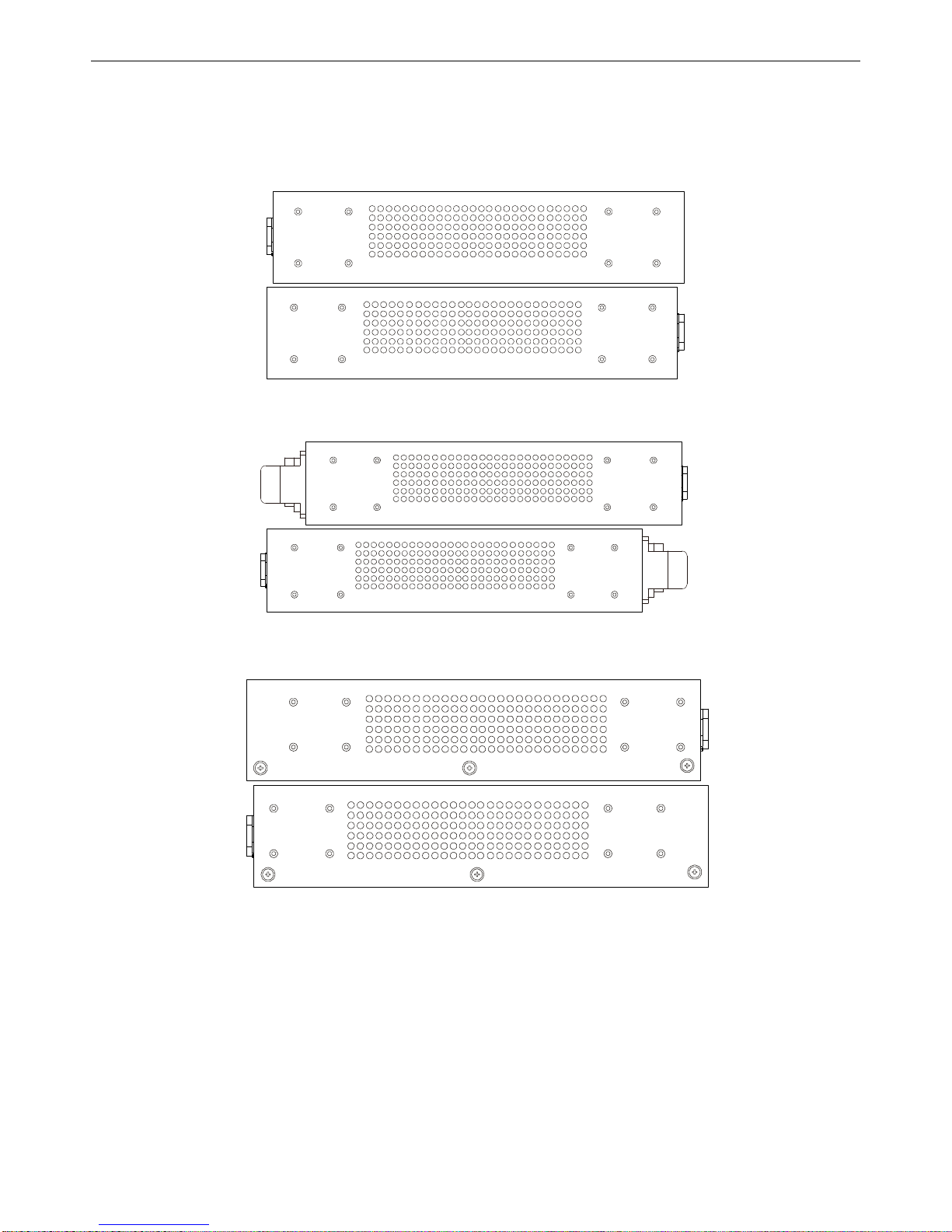
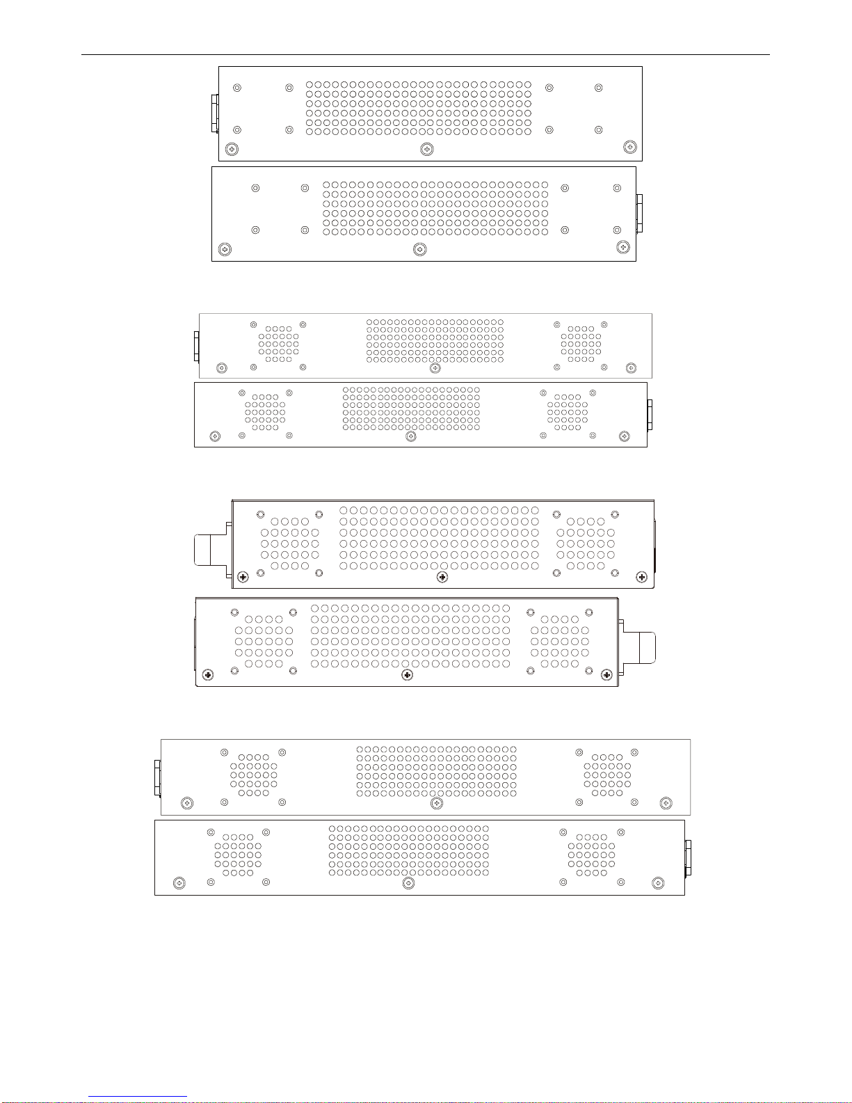
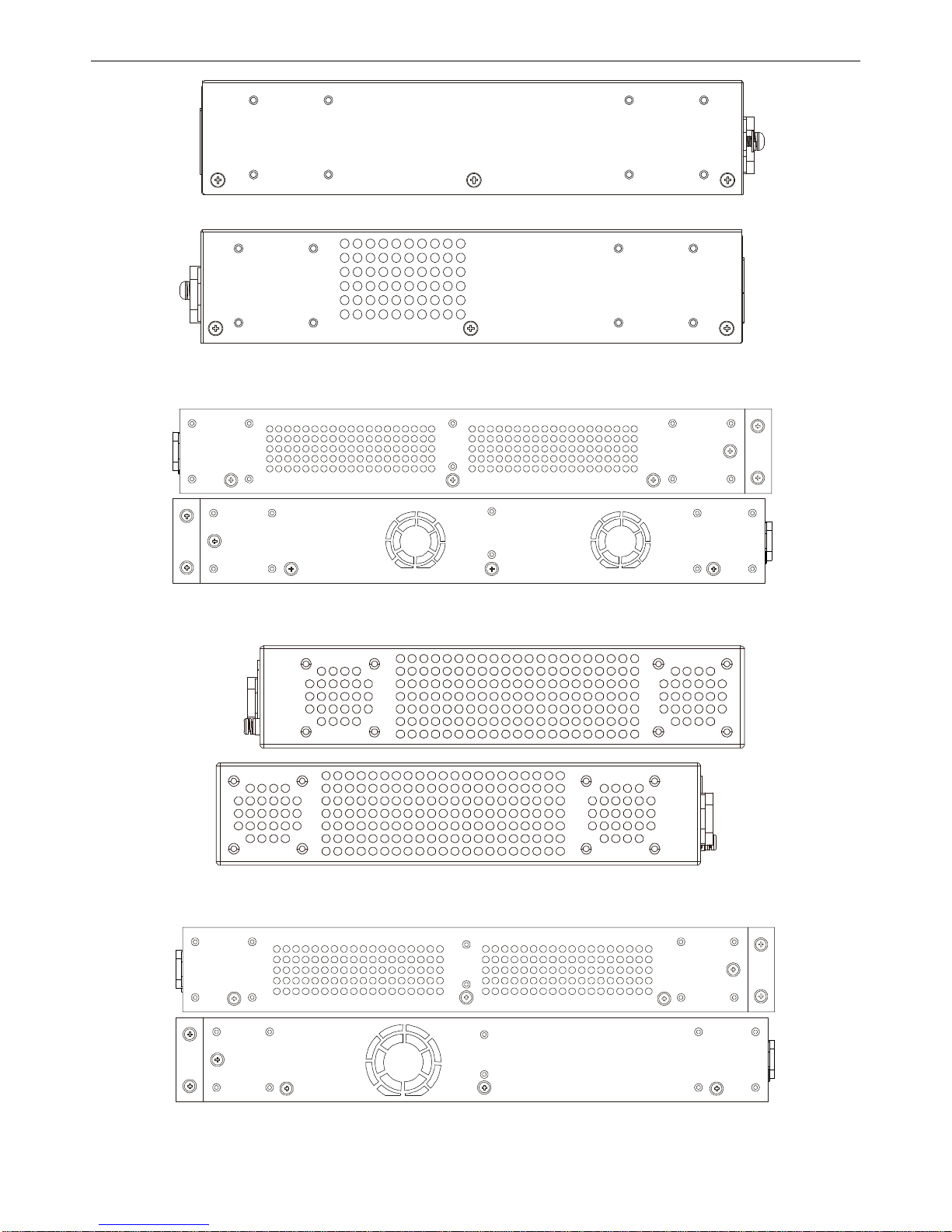
Side Panel Description
The left- and right-hand panels of the Switch have heat vents to dissipate heat. Do not block these openings, and
leave at least 6 inches of space at the rear and sides of the Switch for proper ventilation. Be reminded that without
proper heat dissipation and air circulation, system components might overheat, which could lead to system failure
Figure 1-40. Side panels of the DES-3200-10
Figure 1-41. Side panels of the DES-3200-10-DC
Figure 1-42. Side panels of the DES-3200-18
13
xStack® DES-3200 Series Layer 2 Ethernet Managed Switch Hardware Installation Guide
Figure 1-43. Side panels of the DES-3200-18-DC
Figure 1-44. Side panels of the DES-3200-26
Figure 1-45. Side panels of the DES-3200-26-DC
Figure 1-46. Side panels of the DES-3200-28
14
xStack® DES-3200 Series Layer 2 Ethernet Managed Switch Hardware Installation Guide
Figure 1-47. Side panels of the DES-3200-28F
Figure 1-48. Side panels of the DES-3200-28P
Figure 1-49. Side panels of the DES-3200-28/ME
Figure 1-50. Side panels of the DES-3200-52
15
 Loading...