

D-Link DES-3200-10, DES-3200-10-DC, DES-3200-18, DES-3200-18-DC, DES-3200-26 Service Manual
...Page 1
xStack® DES-3200 Series Layer 2 Managed Fast Ethernet Switch Hardware Installation Guide
1
Page 2

xStack® DES-3200 Series Layer 2 Managed Fast Ethernet Switch Hardware Installation Guide
Information in this document is subject to change without notice.
© 2012 D-Link Corporation. All rights reserved.
Reproduction in any manner whatsoever without the written permission of D-Link C orporation is strictly forbidden.
Trademarks used in this text: D-Link and the D-LINK logo are trademarks of D-Link Corporation; Microsoft and Windows are
registered trademarks of Microsoft Corporation.
Other trademarks and trade names may be used in this document to refer to either the entities claiming the marks and names or
their products. D-Link Corporation disclaims any proprietary interest in trademarks and trade names other than its own.
November, 2012 P/N 651ES32C1035G
FCC Warning
This equipment has been tested and found to comply with the limits for a Class A digital device, pursuant to Part 15 of the FCC
Rules. These limits are designed to provide reasonable protection against harmful interference when the equipment is operated in a
commercial environment. This equipment generates, uses, and can radiate radio frequency energy and, if not installed and used in
accordance with this manual, may cause harmful interference to radio communications. Operation of this equipment in a residential
area is likely to cause harmful interference in which case the user will be required to correct the interference at his own expense.
CE Mark Warning
This is a Class A product. In a domestic environment, this product may cause radio interference in which case the user may be
required to take adequate measures.
Warnung!
Dies ist ein Produkt der Klasse A. Im Wohnbereich kann dieses Produkt Funkstoerungen verursachen. In diesem F all kann vom
Benutzer verlangt werden, angemessene Massnahmen zu ergreifen.
Precaución!
Este es un producto de Clase A. En un entorno doméstico, puede causar interferencias de radio, en cuyo case, pu ede requerirse al
usuario para que adopte las medidas adecuadas.
Attention!
Ceci est un produit de classe A. Dans un environnement domestique, ce produit pourrait causer des interférences radi o, auquel cas
l`utilisateur devrait prendre les mesures adéquates.
Attenzione!
Il presente prodotto appartiene alla classe A. Se utilizzato in ambiente domestico il prodotto può causare interferenze radio, nel cui
caso è possibile che l`utente debba assumere provvedimenti adeguati.
VCCI Warning
この装置は、クラス A 情報技術装置です。この装置を家庭環境で使用すると電波妨害を引き起こすことがあります。この場合には
使用者が適切な 対策を講ずるよう要求されることがあります。VCCI-A
BSMI
此為甲類的資訊技術設備,在居住環境中使用時,可能會造成射頻擾動,在這種情況下,使用者會被要求採取某些適當的對策。
產品 DES-3200-10-DC/DES-3200-18-DC/ DES-3200-26-DC/ DES-3200-52DC 須連接額定電流 2A 至 10A 之斷路器,做為與直流電源
之切斷裝置。
SFP (Mini-GBIC), XENPAK, and XFP Regulatory Compliance
Networks pluggable optical modules meet the following regulatory requirements:
Class 1 Laser Product
EN60825-1+A2:2001 or later, European laser standard
FCC 21 CFR Chapter 1, Subchapter J in accordance with FDA & CDRH requirements
i
Page 3

xStack® DES-3200 Series Layer 2 Managed Fast Ethernet Switch Hardware Installation Guide
Table of Contents
Intended Readers ...................................................................................................................................................iii
Typographical Conventions......................................................................................................................................................iii
Notes, Notices, and Cautions...................................................................................................................................................iii
Safety Instructions ...................................................................................................................................................................iii
Safety Cautions........................................................................................................................................................................iv
General Precautions for Rack-Mountable Products..................................................................................................................v
Protecting Against Electrostatic Discharge ...............................................................................................................................v
Chapter 1 Introduction ...........................................................................................................................................1
Switch Description ...................................................................................................................................................................1
Front Panel Description ........................................................................................................................................................... 2
LED Indicators.......................................................................................................................................................................6
Rear Panel Description.......................................................................................................................................................... 11
Side Panel Description........................................................................................................................................................... 13
Gigabit Combo Ports.............................................................................................................................................................. 16
Chapter 2 Installation ...........................................................................................................................................18
Package Contents.................................................................................................................................................................. 18
Before You Connect to the Network....................................................................................................................................... 18
Installing the Switch without the Rack.................................................................................................................................... 19
Installing the Switch in a Rack ...............................................................................................................................................19
Mounting the Switch in a Standard 19" Rack......................................................................................................................... 20
Power on AC Power............................................................................................................................................................... 20
Power Failure...................................................................................................................................................................... 20
Connecting DC Power ........................................................................................................................................................... 20
Alarm Connector (DES_3200-28/ME only) ............................................................................................................................ 21
Chapter 3 Connecting the Switch .......................................................................................................................23
Switch to End Node ............................................................................................................................................................... 23
Switch to Hub or Switch......................................................................................................................................................... 24
Chapter 4 Introduction to Switch Management ................................................................................................. 25
Management Options............................................................................................................................................................. 25
Web-based Management Interface........................................................................................................................................ 25
SNMP-Based Management ................................................................................................................................................... 25
Connecting the Console Port................................................................................................................................................. 25
First Time Connecting to the Switch ...................................................................................................................................... 26
Password Protection.............................................................................................................................................................. 27
SNMP Settings....................................................................................................................................................................... 28
Traps................................................................................................................................................................................... 28
MIBs.................................................................................................................................................................................... 28
IP Address Assignment.......................................................................................................................................................... 29
Chapter 5 Web-based Switch Configuration......................................................................................................31
Introduction............................................................................................................................................................................ 31
Login to Web Manager........................................................................................................................................................... 31
Web-based User Interface..................................................................................................................................................... 32
Areas of the User Interface................................................................................................................................................. 32
Web Pages ............................................................................................................................................................................ 33
Appendix A – Technical Specifications .............................................................................................................. 34
Appendix B – Cables and Connectors................................................................................................................40
Ethernet Cable....................................................................................................................................................................... 40
Console Cable ....................................................................................................................................................................... 41
Appendix C – Module Specs and Cable Lengths............................................................................................... 42
Warranty & Technical Support.............................................................................................................................43
ii
Page 4
xStack® DES-3200 Series Layer 2 Managed Fast Ethernet Switch Hardware Installation Guide
Intended Readers
Typographical Conventions
Notes, Notices, and Cautions
Safety Instructions
Safety Cautions
General Precautions for Rack-Mountable Products
Protecting Against Electrostatic Discharge
The DES-320
of a Switch in this series. It also contains brief information on how to configure and manage a Switch in this series.
This manual is intended for advanced level users that are familiar with network management concepts and
terminology. For all practical reasons all the Switches in this series will simply be referred to as the Switch throughout
this manual. All example screenshots are taken from the DES-3200-28P Switch.
0 Series Har
Typographical Conventions
Convention Description
dware Installation Guide contains detailed information about the hardware specifications
[ ]
Bold font
Boldface
Typewriter Font
Initial capital letter
Italics
Menu Name > Menu
Option
In a command line, square brackets indicate an optional entry. For example: [copy filename]
means that optionally you can type copy followed by the name of the file. Do not type the
brackets.
Indicates a button, a toolbar icon, menu, or menu item. For example: Open the File menu
and choose Cancel. Used for emphasis. May also indicate system messages or prompts
appearing on your screen. For example: You have mail. Bold font is also used to represent
filenames, program names and commands. For example: use the copy command.
Indicates commands and responses to prompts that must be typed exactly as printed in the
manual.
Indicates a window name. Names of keys on the keyboard have initial capitals. For example:
Click Enter.
Indicates a window name or a field. Also can indicate a variables or parameter that is
replaced with an appropriate word or string. For example: type filename means that you
should type the actual filename instead of the word shown in italic.
Menu Name > Menu Option Indicates the menu structure. Device > Port > Port
Properties means the Port Properties menu option under the Port menu option that is
located under the Device menu.
Notes, Notices, and Cautions
A NOTE indicates important information that helps you make better use of your device.
A NOTICE indicates either potential damage to hardware or loss of data and tells you how to avoid
the problem.
A CAUTION indicates a potential for property damage, personal injury, or death.
Safety Instructions
Use the following safety guidelines to ensure your own personal safety and to help protect your system from potential
damage. Throughout this document, the caution icon (
to review and follow.
) is used to indicate cautions and precautions that you need
iii
Page 5

xStack® DES-3200 Series Layer 2 Managed Fast Ethernet Switch Hardware Installation Guide
Safety Cautions
To reduce the risk of bodily injury, electrical shock, fire, or damage to the equipment, observe the following
precautions.
Observe and follow service markings.
o Do not service any product except as explaine d in your system documentation.
o Opening or re moving covers that are marked with the triangular symbol with a lightning bolt may expose
you to electrical shock.
o Only a trained service technici an should service components inside these compartments.
If any of the following conditions occur, unplug the product from the electrical outlet and replace the part or
contact your trained service provider:
o The power ca ble, extension cable, or plug is damaged.
o An object has fallen into the product.
o The product has been exposed to water.
o The product has been d ropped or damaged.
o The product does not operate correctly when you follow the operating instructions.
Keep your system away from radiators and heat sources. Also, do not block cooling vents.
Do not spill food or liquids on your system components, and never operate the product in a wet environment. If
the system gets wet, see the appropriate section in your troubleshooting guide or contact your trained service
provider.
Do not push any objects into the openings of your system. Doing so can cause fire or electric sho c k by shorting
out interior components.
Use the product only with approved equipment.
Allow the product to cool before removing covers or touching internal components.
Operate the product only from the type of external power source indicated on the electrical ratings label. If you
are not sure of the type of power source required, consult your service provider or local power company.
To help avoid damaging your system, be sure the voltage on the power supply is set to match the power
available at your location:
o 115 volts (V)/60 hert z (Hz) in most of North and South America and some Far Eastern countries such as
South Korea and Taiwan
o 100 V/50 Hz in eastern Japan and 1 00 V/60 Hz in western Japan
o 230 V/50 Hz in most of Europe, the Middle East, and the Far East
Also, be sure that attached devices are electrically rated to operate with the power available in your location.
Use only approved power cable(s). If you have not been provided with a power cable for your system or for any
AC-powered option intended for your system, purchase a power cable that is approved for use in your country.
The power cable must be rated for the product and for the voltage and current marked on the product's
electrical ratings label. The voltage and current rating of the cable should be greater than the ratings marked on
the product.
To help prevent electric shock, plug the system and peripheral power cables into properly grounded electrical
outlets. These cables are equipped with three-prong plugs to help ensure proper grounding. Do not use adapter
plugs or remove the grounding prong from a cable. If you must use an extension cable, use a 3-wire cable with
properly grounded plugs.
Observe extension cable and power strip ratings. Make sure that the total ampere rating of all produ cts plugged
into the extension cable or power strip does not exceed 80 percent of the ampere ratings limit for the extension
cable or power strip.
To help protect your system from sudden, transient increases and decreases in electrical power, use a surge
suppressor, line conditioner, or uninterruptible power supply (UPS).
Position system cables and power cables carefully; route cables so that they cannot be stepped on or tripped
over. Be sure that nothing rests on any cables.
Do not modif
modifications. Always follow your local/national wiring rules.
When connecting or disconnecting power to hot-pluggable power supplies, if offered with your system, observe
the following guidelines:
o Install the power sup ply before connecting the power cable to the power supply.
o Unplug the power cable before removing the power supply.
y power cables or plugs. Consult a licensed electrician or your power company for site
iv
Page 6
xStack® DES-3200 Series Layer 2 Managed Fast Ethernet Switch Hardware Installation Guide
o If the system has multipl
cables from the power supplies.
Move products with care; ensure that all casters and/or stabilizers are firmly connected to the system. Avoid
sudden stops and uneven surfaces.
e sources of power, disconnect power from the system by unplugging all power
General Precautions for Rack-Mountable Products
Observe the following precautions for rack stability and safety. Also, refer to the rack installation documentation
accompanying the system and the rack for specific caution statements and procedures.
Systems are considered to be components in a rack. Thus, "component" refers to any system as well as to
various peripherals or supporting hardware.
Before working on the rack, make sure that the stabilizers are secured to the rack, extended to the floor, and
that the full weight of the rack rests on the floor. Install front and side stabilizers on a single rack or front
stabilizers for joined multiple racks before working on the rack.
Always load the rack from the bottom up, and load the heaviest item in the rack first.
Make sure that the rack is level and stable before extending a component from the rack.
Use caution when pressing the component rail release latches and sliding a component into or out of a rack;
the slide rails can pinch your fingers.
After a component is inserted into the rack, carefully extend the rail into a locking position, and then slide the
component into the rack.
Do not overload the AC supply branch circuit that provides power to the rack. The total rack load should n ot
exceed 80 percent of the branch circuit rating.
Ensure that proper airflow is provided to components in the rack.
Do not step on or stand on any component when servicing other components in a rack.
NOTE: A qualified electrician must perform all connections to DC power and to safety grounds. All
electrical wiring must comply with applicable local, regional or national codes a nd practices.
CAUTION: Never defeat the ground conductor or operate the equipment in the absence of a suitably
installed ground conductor. Contact the appropriate electrical inspection authority or an electrician if
you are uncertain that suitable grounding is available.
CAUTION: The system chassis must be positively grounded to the rack cabinet frame. Do not
attempt to connect power to the system until grounding cables are connected. A qualified electrical
inspector must inspect completed power and safety ground wiring. An energy hazard will exist if the
safety ground cable is omitted or disconnected.
CAUTION: Do not replace the battery with an incorrect type. The risk of explosion exists if the
replacement battery is not the correct lithium battery type. Dispose of used batteries according to the
instructions.
Protecting Against Electrostatic Discharge
Static electricity can harm delicate components inside your system. To prevent static damage, discharge static
electricity from your body before you touch any of the electronic components, such as the microprocessor. You can do
so by periodically touching an unpainted metal surface on the chassis.
You can also take the following steps to prevent damage from electrostatic discharge (ESD):
1. When unpacking a static-sensitive component from its shipping carton, do not re move the component from the
antistatic packing material until you are ready to install the component in your system. Just before unwrapping
the antistatic packaging, be sure to discharge static electricity from your body.
2. When transporting a sensit ive component, first place it in an antistatic container or packaging.
3. Handle all sensitive compo nents in a static-safe area. If possible, use antistatic floor pads, workbench pads and
an antistatic grounding strap.
v
Page 7

xStack® DES-3200 Series Layer 2 Ethernet Managed Switch Hardware Installation Guide
Chapter 1 Introduction
Switch Description
Front Panel Description
Rear Panel Description
Side Panel Description
Gigabit Combo Ports
Switch Description
The DES-3200 Series Hardware Installation Guide describes the hardware installation and specifications
concerning the DES-3200 Series switches. These switches are identical in configuration and very similar in basic
hardware and consequentially, most of the information in this manual will be universal to the total group of switches.
This manual concentrates on the Hardware Version C1.
The DES-3200 Series switches are equipped with Copper ports (10/100Mbps) and SFP ports (100/1000Mbps) that
can be used to attach various networking devices to the network like Computers, Notebooks, Print Servers, Network
Attached Storage devices, IP Cameras, VoIP PBX devices, and other Switches. The Small Form Factor Portable (SFP)
combo ports can be used together with fiber-optical transceivers in order to connect various other networking devices,
using a fiber-optic connection, to the network at Gigabit Ethernet speeds over great distances.
The DES-3200 Series switches provide unsurpassed performance, fault tolerance, scalable flexibility, robust security,
standard-based interoperability and impressive technology to future-proof departmental and enterprise network
deployments with an easy migration path.
The Series features the following list of switches:
Switch Description
DES-3200-10
DES-3200-10-DC
DES-3200-18
DES-3200-18-DC
DES-3200-26
DES-3200-26-DC
DES-3200-28
Eight 10/100Mbps Copper Ports, One 100/1000Mbps SFP Port, One Combo
10/100/1000Mbps Copper / 100/1000Mbps SFP Port, and One RJ-45 Console Port for
out-of-band CLI configuration.
Eight 10/100Mbps Copper Ports, One 100/1000Mbps SFP Port, One Combo
10/100/1000Mbps Copper / 100/1000Mbps SFP Port, and One RJ-45 Console Port for
out-of-band CLI configuration.
Sixteen 10/100Mbps Copper Ports, One 100/1000Mbps SFP Port, One Combo
10/100/1000Mbps Copper / 100/1000Mbps SFP Port, and One RJ-45 Console Port for
out-of-band CLI configuration.
Sixteen 10/100Mbps Copper Ports, One 100/1000Mbps SFP Port, One Combo
10/100/1000Mbps Copper / 100/1000Mbps SFP Port, and One RJ-45 Console Port for
out-of-band CLI configuration.
Twenty-four 10/100Mbps Copper Ports, Two Combo 10/100/1000Mbps Copper /
100/1000Mbps SFP Ports, and One RJ-45 Console Port for out-of-band CLI
configuration.
Twenty-four 10/100Mbps Copper Ports, Two Combo 10/100/1000Mbps Copper /
100/1000Mbps SFP Ports, and One RJ-45 Console Port for out-of-band CLI
configuration.
Twenty-four 10/100Mbps Copper Ports, Two Combo 10/100/1000Mbps Copper /
100/1000Mbps SFP Ports, Two 100/1000Mbps SFP Ports, and One RJ-45 Console
Port for out-of-band CLI configuration.
DES-3200-28F
DES-3200-28P
Twenty-four 100Mbps SFP Ports, Four Combo 10/100/1000Mbps Copper /
100/1000Mbps SFP Ports, and One RJ-45 Console Port for out-of-band CLI
configuration.
Twenty-four 10/100Mbps Power over Ethernet Copper Ports, Two Combo
1
Page 8
xStack® DES-3200 Series Layer 2 Ethernet Managed Switch Hardware Installation Guide
10/100/1000
Ports, and One RJ-45 Console Port for out-of-band CLI configuration.
DES-3200-28/ME
DES-3200-52
DES-3200-52-DC
DES-3200-52P
These switches have a combination of 1000BASE-T ports and SFP ports that may be used in to uplink various
network devices to the Switch, including PCs, hubs and other switches to provide a gigabit Ethernet uplink in fullduplex mode. The SFP (Small Form Factor Portable) combo ports are used with fiber-optical transceiver cabling in
order to uplink various other networking devices for a gigabit link that may span great distan ces.
Twenty-four 10/100Mbps Copper Ports, Two Combo 10/100/1000Mbps Copper /
100/1000Mbps SFP Ports, Two 100/1000Mbps SFP Ports, One RJ-45 Console Port for
out-of-band CLI configuration, and One Alarm Connector Port.
Forty-eight 10/100Mbps Copper Ports, Two Combo 10/100/1000Mbps Copper /
100/1000Mbps SFP Ports, Two 100/1000Mbps SFP Ports, and One RJ-45 Console
Port for out-of-band CLI configuration.
Forty-eight 10/100Mbps Copper Ports, Two Combo 10/100/1000Mbps Copper /
100/1000Mbps SFP Ports, Two 100/1000Mbps SFP Ports, and One RJ-45 Console
Port for out-of-band CLI configuration.
Forty-eight 10/100Mbps Power over Ethernet Copper Ports, Two Combo
10/100/1000Mbps Copper / 100/1000Mbps SFP Ports, Two 10/100/1000Mbps Copper
Ports, and One RJ-45 Console Port for out-of-band CLI configuration.
Mbps Copper / 100/1000Mbps SFP Ports, Two 10/100/1000Mbps Copper
Front Panel Description
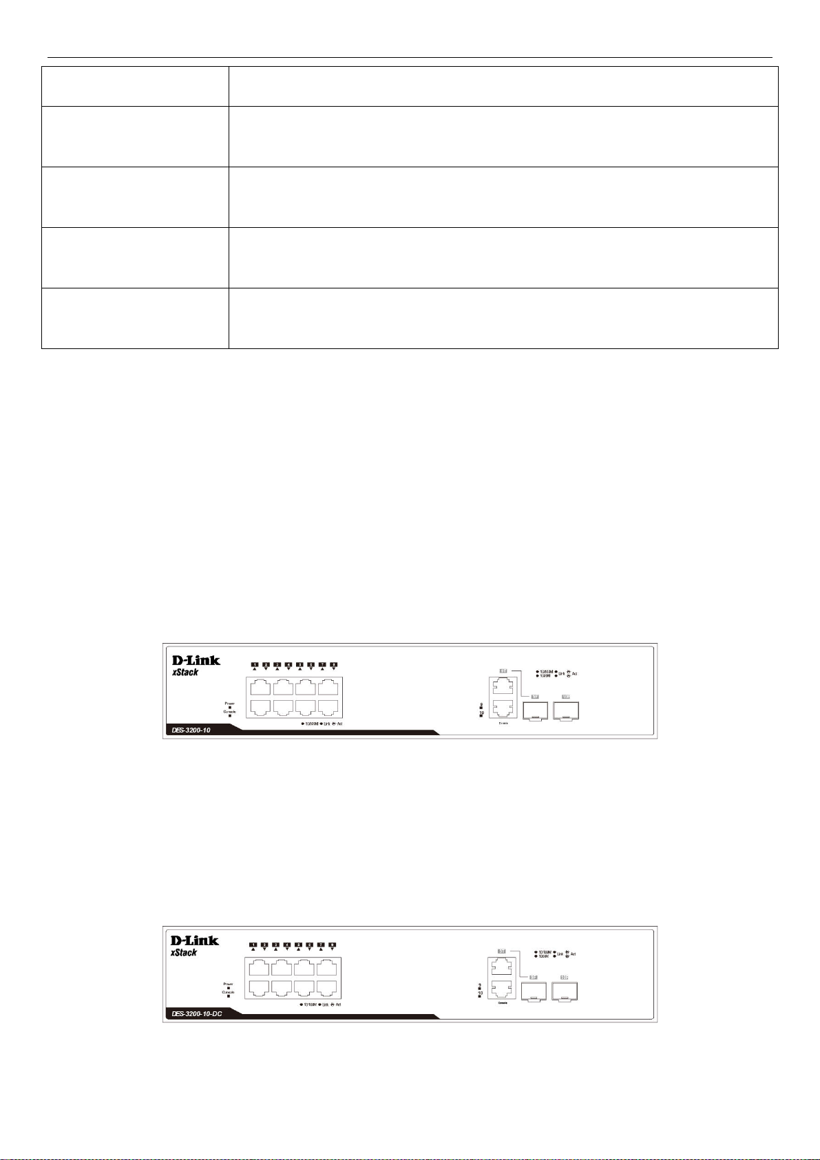
The front panel of the DES-3200-10 switch consists out of the following:
Eight 10/100Mbps Copper Ports
One Combo 10/100/1000Mbps Copper / 100/1000Mbps SFP port
One 100/1000Mbps SFP Port
One RJ-45 Console Port
LEDs for Power, Console, Link/Act for port 1 to 8, and Link/Act/Speed for port 9 and 10
Figure 1-1. Front Panel of the DES-3200-10
The front panel of the DES-3200-10-DC switch consists out of the following:
Eight 10/100Mbps Copper Ports
One Combo 10/100/1000Mbps Copper / 100/1000Mbps SFP port
One 100/1000Mbps SFP Port
One RJ-45 Console Port
LEDs for Power, Console, Link/Act for port 1 to 8, and Link/Act/Speed for port 9 and 10
Figure 1-2. Front Panel of the DES-3200-10-DC
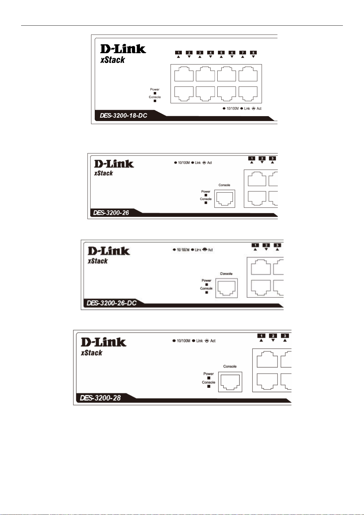
The front panel of the DES-3200-18 switch consists out of the following:
2
Page 9
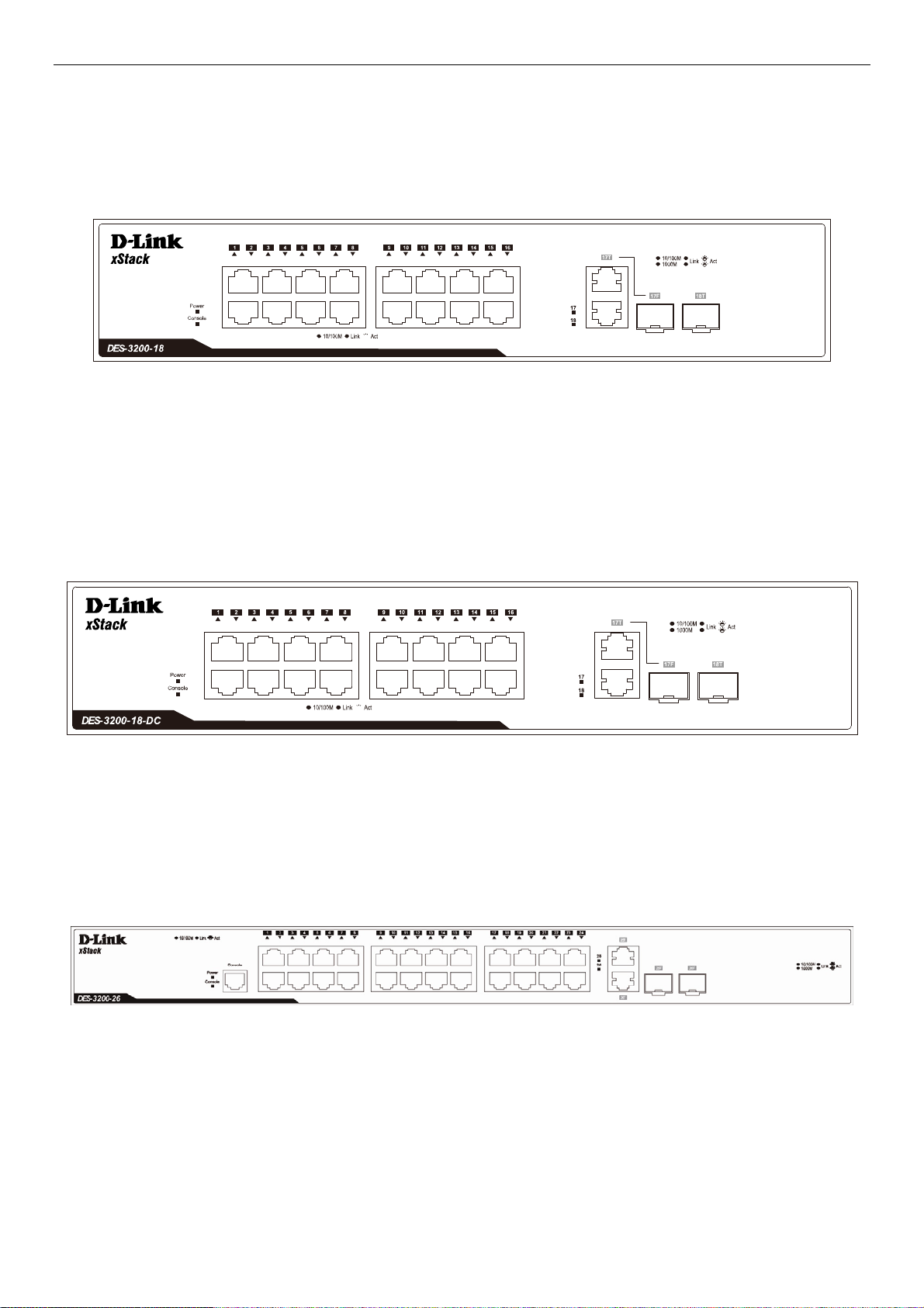
xStack® DES-3200 Series Layer 2 Ethernet Managed Switch Hardware Installation Guide
Sixteen 10/10
0Mbps Copper Ports
One Combo 10/100/1000Mbps Copper / 100/1000Mbps SFP port
One 100/1000Mbps SFP Port
One RJ-45 Console Port
LEDs for Power, Console, Link/Act for port 1 to 16, and Link/Act/Speed for port 17 and 18
Figure 1-3. Front Panel of the DES-3200-18
The front panel of the DES-3200-18-DC switch consists out of the following:
Sixteen 10/100Mbps Copper Ports
One Combo 10/100/1000Mbps Copper / 100/1000Mbps SFP port
One 100/1000Mbps SFP Port
One RJ-45 Console Port
LEDs for Power, Console, Link/Act for port 1 to 16, and Link/Act/Speed for port 17 and 18
Figure 1-4. Front Panel of the DES-3200-18-DC
The front panel of the DES-3200-26 switch consists out of the following:
Twenty-four 10/100Mbps Copper Ports
Two Combo 10/100/1000Mbps Copper / 100/1000Mbps SFP ports
One RJ-45 Console Port
LEDs for Power, Console, Link/Act for port 1 to 24, and Link/Act/Speed for port 25 and 26
Figure 1-5. Front Panel of the DES-3200-26
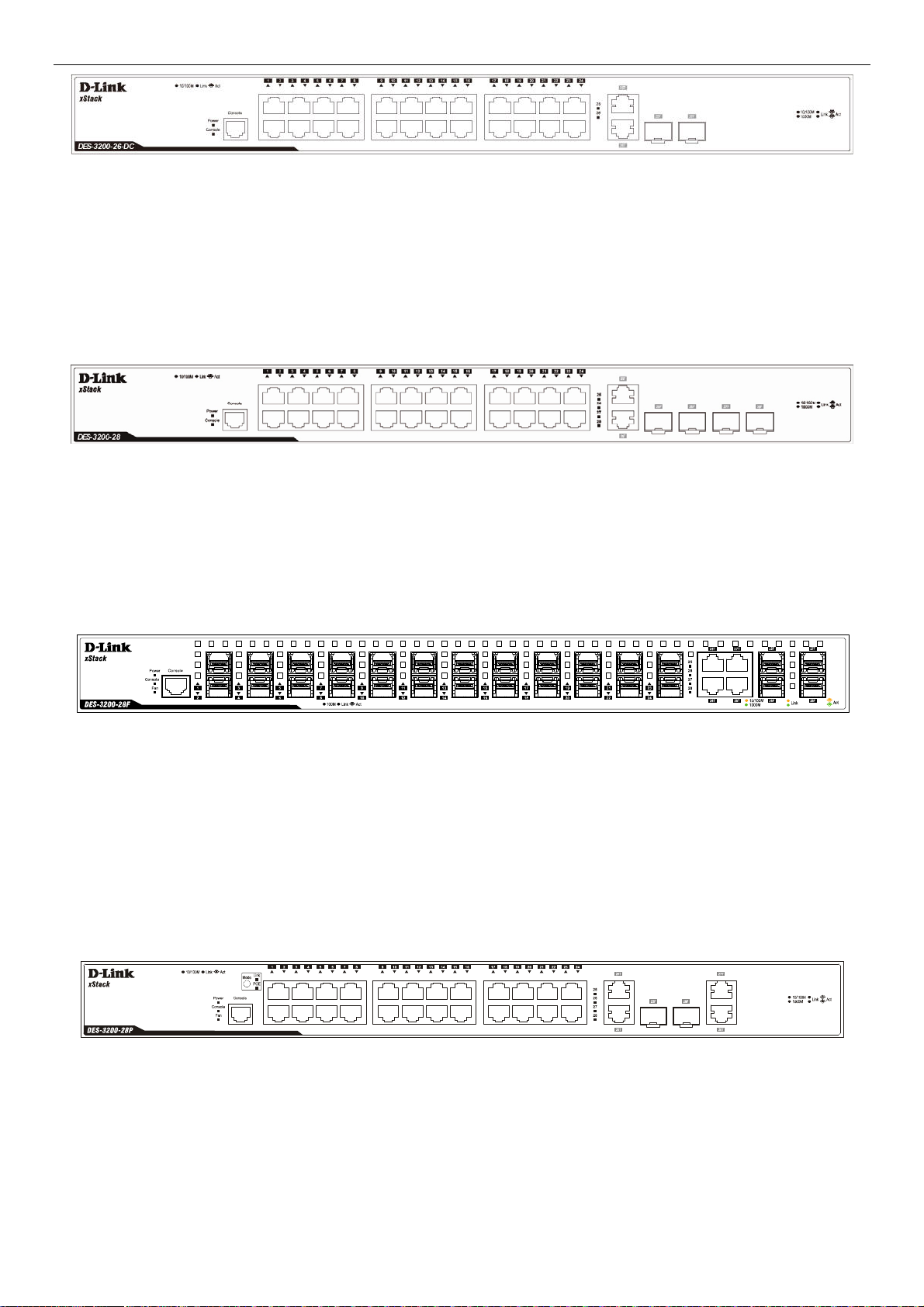
The front panel of the DES-3200-26-DC switch consists out of the following:
Twenty-four 10/100Mbps Copper Ports
Two Combo 10/100/1000Mbps Copper / 100/1000Mbps SFP ports
One RJ-45 Console Port
LEDs for Power, Console, Link/Act for port 1 to 24, and Link/Act/Speed for port 25 and 26
3
Page 10
xStack® DES-3200 Series Layer 2 Ethernet Managed Switch Hardware Installation Guide
Figure 1-6. Front Panel of the DES-3200-26-DC
The front panel of the DES-3200-28 switch consists out of the following:
Twenty-four 10/100Mbps Copper Ports
Two Combo 10/100/1000Mbps Copper / 100/1000Mbps SFP ports
Two 100/1000Mbps SFP Ports
One RJ-45 Console Port
LEDs for Power, Console, Link/Act for port 1 to 24, and Link/Act/Speed for port 25 to 28
Figure 1-7. Front Panel of the DES-3200-28
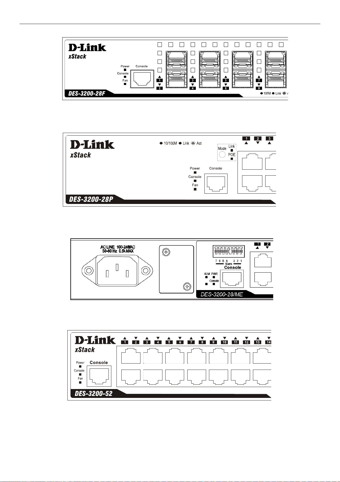
The front panel of the DES-3200-28F switch consists out of the following:
Twenty-four 100Mbps SFP Ports
Four Combo 10/100/1000Mbps Copper / 100/1000Mbps SFP Ports
One RJ-45 Console Port
LEDs for Power, Console, Fan, Link/Act for port 1 to 24, and Link/Act/Speed for port 25 to 28
Figure 1-8. Front Panel of the DES-3200-28F
The front panel of the DES-3200-28P switch consists out of the following:
Twenty-four 10/100Mbps Power over Ethernet Copper Ports
Two Combo 10/100/1000Mbps Copper / 100/1000Mbps SFP ports
Two 10/100/1000Mbps Copper Ports
One RJ-45 Console Port
Link/PoE button
LEDs for Link, PoE, Power, Console, Fan, Link/Act for port 1 to 24, and Link/Act/Speed for port 25 to 28
Figure 1-9. Front Panel of the DES-3200-28P
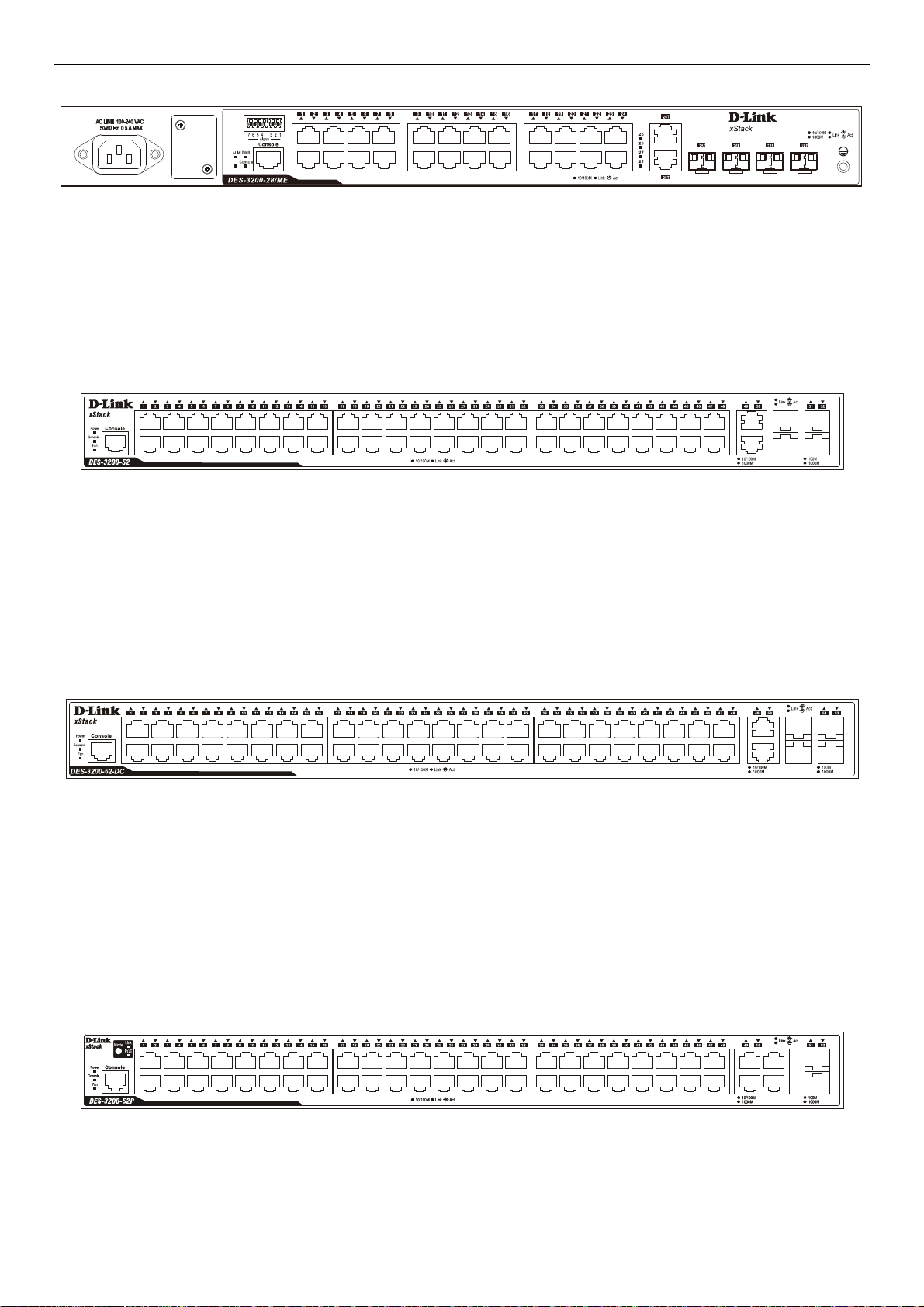
The front panel of the DES-3200-28/ME switch consists out of the following:
Twenty-four 10/100Mbps Copper ports
Two Combo 10/100/1000Mbps Copper 100/1000Mbps SFP ports, Two 100/1000Mbps SFP ports
One RJ-45 Console port
One Alarm Connector
LEDs for Power, Console, Alarm, and Link/Act/Speed for each port
4
Page 11
xStack® DES-3200 Series Layer 2 Ethernet Managed Switch Hardware Installation Guide
Figure 1-10. Front Panel of the DES-3200-28/ME
The front panel of the DES-3200-52 switch consists out of the following:
Forty-eight 10/100Mbps Copper Ports
Two Combo 10/100/1000Mbps Copper / 100/1000Mbps SFP ports
Two 100/1000Mbps SFP Ports
One RJ-45 Console Port
LEDs for Power, Console, Fan, Link/Act for port 1 to 48, and Link/Act/Speed for port 49 to 52
Figure 1-11. Front Panel of the DES-3200-52
The front panel of the DES-3200-52-DC switch consists out of the following:
Forty-eight 10/100Mbps Copper Ports
Two Combo 10/100/1000Mbps Copper / 100/1000Mbps SFP Ports
Two 100/1000Mbps SFP Ports
One RJ-45 Console Port
LEDs for Power, Console, Fan, Link/Act for port 1 to 48, and Link/Act/Speed for port 49 to 52
Figure 1-12. Front Panel of the DES-3200-52-DC
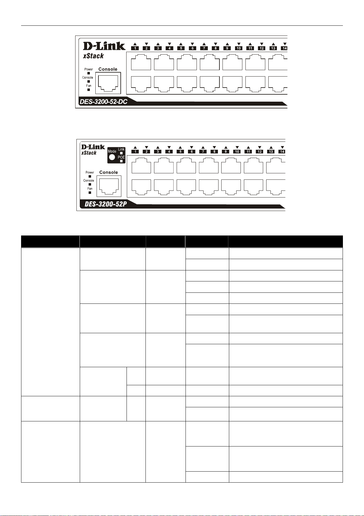
The front panel of the DES-3200-52P switch consists out of the following:
Forty-eight 10/100Mbps Power over Ethernet Copper Ports
Two Combo 10/100/1000Mbps Copper / 100/1000Mbps SFP ports
Two 10/100/1000Mbps Copper Ports
Link/PoE button
One RJ-45 Console Port
LEDs for Link, PoE, Power, Console, Fan, Link/Act for port 1 to 48, and Link/Act/Speed for port 49 to 52
Figure 1-13. Front Panel of the DES-3200-52P
5
Page 12
xStack® DES-3200 Series Layer 2 Ethernet Managed Switch Hardware Installation Guide
LED Indicators
The Switch supports LED indicators for Power, Console, Fan, and Link/Act or Link/Act/Speed for each port. The
following shows the LED indicators for the DES-3200 Series along with an explanation of each indicator.
Figure 1-14. LED Indicators on DES-3200-10
Figure 1-15. LED Indicators on DES-3200-10-DC
Figure 1-16. LED Indicators on DES-3200-18
6
Page 13
xStack® DES-3200 Series Layer 2 Ethernet Managed Switch Hardware Installation Guide
Figure 1-17. LED Indicators on DES-3200-18-DC
Figure 1-18. LED Indicators on DES-3200-26
Figure 1-19 LED Indicators on DES-3200-26-DC
Figure 1-20. LED Indicators on DES-3200-28
7
Page 14
xStack® DES-3200 Series Layer 2 Ethernet Managed Switch Hardware Installation Guide
Figure 1-21. LED Indicators on DES-3200-28F
Figure 1-22. LED Indicators on DES-3200-28P
Figure 1-23. LED Indicators on DES-3200-28/ME
Figure 1-24. LED Indicators on DES-3200-52
8
Page 15
xStack® DES-3200 Series Layer 2 Ethernet Managed Switch Hardware Installation Guide
Figure 1-25. LED Indicators on DES-3200-52-DC
Figure 1-26. LED Indicators on DES-3200-52P
Location LED Indicative Color Status Description
Solid Light Power on.
Light off Power off.
Solid Light Console on.
Blinking POST is in progress.
Light off Console off.
Solid Light Attached device failure is detected.
Light off
Attached device is off or functioning
properly.
Blinking Light When any of the fans has failed.
Light off Whe n all fans work no rmally.
When 10/100Mbps port is in Link/Act
Mode.
Per Device
Power
Console
Alarm (DES-320028/ME only)
Fan
(DES-3200-
28F/28P/52/52-DC/52P
only)
Port LED Mode
Link
(DES-320028P/52P only)
POE
Green
Green
Red
Red
Green Solid Light
Green Solid Light When 10/100Mbps port is in PoE Mode.
LED Per
10/100Mbps
Copper Port
RPS (Only for
Redundant
Power)
Link/Act
Solid Light RPS in use
Green
Light off RPS not in use
When there is a secure 10/100Mbps
Solid Green
Ethernet connection (or link) at any of the
ports.
Green
Blinking Green
When there is reception or transmission
(i.e. Activity—Act) of data occurring at a
10/100Mbps Ethernet connected port.
Light off No lin k.
9
Page 16

xStack® DES-3200 Series Layer 2 Ethernet Managed Switch Hardware Installation Guide
LED Per
10/100/1000Mbps
Copper Port
Link/Act/Speed
Green/Amber
Solid Green When there is a secure 1000Mbps
Ethernet connection (or link) at any of the
ports.
Blinking Green When there is reception or transmission
(i.e. Activity—Act) of data occurring at a
1000Mbps Ethernet connected port.
Solid Amber When there is a secure 10/100Mbps
Ethernet connection (or link) at any of the
ports.
Blinking Amber When there is reception or transmission
(i.e. Activity—Act) of data occurring at a
10/100Mbps Ethernet connected port.
Light off No lin k.
LED Per
10/100Mbps Port in
PoE Mode (DES3200-28P/52P only)
LED Per 100Mbps
SFP Port (DES3200-28F only)
LED Per
100/1000Mbps SFP
Port
PoE
Link/Act
Link/Act/Speed
Green
Green
Green/Amber
Solid Green Power feeding.
Blinking Green Error Condition
Light off No po wer feeding.
Solid Green When there is a secure 100Mbps
Ethernet connection (or link) at any of the
ports.
Blinking Green When there is reception or transmission
(i.e. Activity—Act) of data occurring at a
100Mbps Ethernet connected port.
Light off No lin k.
Solid Green When there is a secure 1000Mbps
Ethernet connection (or link) at any of the
ports.
Blinking Green When there is reception or transmission
(i.e. Activity—Act) of data occurring at a
1000Mbps Ethernet connected port.
Solid Amber When there is a secure 100Mbps
Ethernet connection (or link) at any of the
ports.
Blinking Amber When there is reception or transmission
(i.e. Activity—Act) of data occurring at a
100Mbps Ethernet connected port.
Light off No lin k.
10
Page 17

xStack® DES-3200 Series Layer 2 Ethernet Managed Switch Hardware Installation Guide
Rear Panel Description
The rear panel of the Switch contains an AC or DC power connector. The AC power connector is a standard threepronged connector that supports the power cord. Plug-in the female connector of the provided power cord into this
socket, and the male side of the cord into a power outlet. The Switch automatically adjusts its power setting to any
supply voltage in the range from 100 to 240 VAC at 50 to 60 Hz. The DC power supply has a three-terminal wiring
block consisting of a positive (+), a negative (-) and a safety ground terminal. Connect the Kensington -compatible
security lock, at the rear of the switch, to a secure immovable device. Insert the lock into the notch and turn the key to
secure the lock.
ACLINE
100-240 VAC
50-60Hz
0.
3AMAX
Figure 1-27. Rear panel view of the DES-3200-10
-48 V
0.4A MA X
-48V -48V RET
Figure 1-28. Rear panel view of the DES-3200-10-DC
Figure 1-29. Rear panel view of the DES-3200-18
Figure 1-30. Rear panel view of the DES-3200-18-DC
Figure 1-31. Rear panel view of the DES-3200-26
Figure 1-32. Rear panel view of the DES-3200-26-DC
11
Page 18

xStack® DES-3200 Series Layer 2 Ethernet Managed Switch Hardware Installation Guide
Figure 1-33. Rear panel view of the DES-3200-28
Figure 1-34. Rear panel view of the DES-3200-28F
Figure 1-35. Rear panel view of the DES-3200-28P
Figure 1-36. Rear panel view of the DES-3200-28/ME
Figure 1-37. Rear panel view of the DES-3200-52
-48V 1.1AMAX
-48V -48VRET
Figure 1-38. Rear panel view of the DES-3200-52-DC
Figure 1-39. Rear panel view of the DES-3200-52P
12
Page 19

xStack® DES-3200 Series Layer 2 Ethernet Managed Switch Hardware Installation Guide
Side Panel Description
The left- and right-hand panels of the Switch have heat vents to dissipate heat. Do not block these openings, and
leave at least 6 inches of space at the rear and sides of the Switch for proper ventilation. Be reminded that without
proper heat dissipation and air circulation, system components might overheat, which could lead to system failure
Figure 1-40. Side panels of the DES-3200-10
Figure 1-41. Side panels of the DES-3200-10-DC
Figure 1-42. Side panels of the DES-3200-18
13
Page 20

xStack® DES-3200 Series Layer 2 Ethernet Managed Switch Hardware Installation Guide
Figure 1-43. Side panels of the DES-3200-18-DC
Figure 1-44. Side panels of the DES-3200-26
Figure 1-45. Side panels of the DES-3200-26-DC
Figure 1-46. Side panels of the DES-3200-28
14
Page 21

xStack® DES-3200 Series Layer 2 Ethernet Managed Switch Hardware Installation Guide
Figure 1-47. Side panels of the DES-3200-28F
Figure 1-48. Side panels of the DES-3200-28P
Figure 1-49. Side panels of the DES-3200-28/ME
Figure 1-50. Side panels of the DES-3200-52
15
Page 22

xStack® DES-3200 Series Layer 2 Ethernet Managed Switch Hardware Installation Guide
Figure 1-51. Side panels of the DES-3200-52-DC
Figure 1-52. Side panels of the DES-3200-52P
Gigabit Combo Ports
The DES-3200 Series features either two or four Gigabit Ethernet Combo ports. These ports are 1000BASE-T copper
ports (optional) and Small Form Factor Portable (SFP) ports (optional). See the diagram below to view the two SFP
port modules being plugged into the Switch. Please note that although these two front panel modules can be used
simultaneously, the ports must be different. The SFP port will always have the highest priority.
Figure 1-53. Inserting the SFP modules into the Switch
16
Page 23

xStack® DES-3200 Series Layer 2 Ethernet Managed Switch Hardware Installation Guide
Figure 1- 27. Installing the SFP Module
The Switch is equipped with SFP ports, which are to be used with fiber-optical transceiver cabling in order to uplink
various other networking devices for a gigabit link that may span great distances. For a full list of supported SFP
transceivers, for this switch series, refer to the Appendix A.
17
Page 24

xStack® DES-3200 Series Layer 2 Ethernet Managed Switch Hardware Installation Guide
Chapter 2 Installation
Package Contents
Before You Connect to the Network
Installing the Switch without the Rack
Installing the Switch in a Rack
Mounting the Switch in a Standard 19" Rack
Power on AC Power
Connecting DC Power
Package Contents
Open the shipping carton of the Switch and carefully unpack its contents. The carton should contain the following
items:
One Stand-alone DES-3200 Series Switch
One AC power cord
Rack mounting kit (two brackets and screws)
Four rubber feet with adhesive backing
RJ-45 console cable
Quick Installation Guide
This manual on CD, including a D-View trial version
If any item is missing or damaged, please contact your local D-Link Reseller for replacement.
Before You Connect to the Network
The site where you install the Switch may greatly affect its performance. Please follow these guidelines for setting up
the Switch.
Install the Switch on a sturdy, level surface that can support at least 7kg (15.43lbs) of weight. Do not place
heavy objects on the Switch.
The power outlet should be within 1.82 meters (6 feet) of the Switch.
Visually inspect the power cord and see that it is fully secured to the AC power port.
Make sure that there is proper heat dissipation from and adequate ventilation around the Switch. Leave at
least 10 cm (4 inches) of space at the front and rear of the Switch for ventilation.
Install the Switch in a fairly cool and dry place for the acceptable temperature and humidity operating ranges.
Install the Switch in a site free from strong electromagnetic field generators (such as motors), vibration, dust,
and direct exposure to sunlight.
When installing the Switch on a level surface, attach the rubber feet to the bottom of the device. The rubber
feet cushion the Switch, protect the casing from scratches and prevent it from scratch ing other surfaces.
18
Page 25

xStack® DES-3200 Series Layer 2 Ethernet Managed Switch Hardware Installation Guide
Installing the Switch without the Rack
When installing the Switch on a desktop or shelf, the rubber feet included with the Switch should first be attached.
Attach these cushioning feet on the bottom at each corner of the device. Allow enough ventilation space between the
Switch and any other objects in the vicinity.
Figure 2-1. Prepare Switch for installation on a desktop or shelf
Installing the Switch in a Rack
The Switch can be mounted in a standard 19" rack. Use the following diagrams as a guide.
Figure 2-2. Fasten mounting brackets to Switch
Fasten the mounting brackets to the Switch using the screws provided. With the brackets attached securely, the
Switch can be mounted in a standard rack as shown in the next figure.
19
Page 26

xStack® DES-3200 Series Layer 2 Ethernet Managed Switch Hardware Installation Guide
Mounting the Switch in a Standard 19" Rack
CAUTION: Installing systems in a rack without the front and side stabilizers installed could cause the
rack to tip over, potentially resulting in bodily injury under certain circumstances. Therefore, always
install the stabilizers before installing components in the rack. After installing components in a rack, do
not pull more than one component out of the rack on its slide assemblies at one time. The weight of
more than one extended component could cause the rack to tip over and may result in injury.
Figure 2-3. Installing Switch in a rack
Power on AC Power
Plug one end of the AC power cord into the power connector of the Switch and the other end into the local power
source outlet.
After the Switch is powered on, the LED indicators will momentarily be on. This solid light represents a reset of the
system.
Power Failure
For AC power supply units, as a precaution, in the event of a power failure, unplug the Switch. When power has
resumed, plug the Switch back in.
CAUTION: Installing systems in a rack without the front and side stabilizers installed could cause the
rack to tip over, potentially resulting in bodily injury under certain circumstances. Therefore, always
install the stabilizers before installing components in the rack. After installing components in a rack, do
not pull more than one component out of the rack on its slide assemblies at one time. The weight of
more than one extended component could cause the rack to tip over and may result in injury.
Connecting DC Power
Follow the instructions below to connect the DC power supply of the DES-3200-10-DC, DES-3200-18-DC, DES3200-26-DC and DES-3200-52-DC to the DC power source.
20
Page 27

xStack® DES-3200 Series Layer 2 Ethernet Managed Switch Hardware Installation Guide
Figure 2-4. Close-up view of Power Receptacle
1. The DC power supply has a three-terminal wiring block consisting of a positive (+), a negative (-) and a safety
ground terminal.
2. Firmly attach the DC power to the negative and positive contacts on the wiring assembly.
a. The negative pole (-) connects to the -48V contact.
b. The positive pole (+) connects to the -48V Return contact.
c. If available, an earth ground may be connected to the center contact post.
3. Tighten the contact screws to secure the connection.
NOTE: Use a minimum 18 gauge (AWG) wire. All power connection wiring should conform to the
rules and regulations in the National Electrical Code (NEC), as well as any local codes. A branch
circuit over current protection must be rated between 2A to 10A.
CAUTION: This equipment must be grounded.
CAUTION: This equipment must be installed and maintained by qualified service personnel only.
Alarm Connector (DES_3200-28/ME only)
Connect alarm and/or intrusion detection devices to the alarm connector to trigger events.
Figure 2-1 Alarm Connector
21
Page 28

xStack® DES-3200 Series Layer 2 Ethernet Managed Switch Hardware Installation Guide
Alarm Connector Port
Contact Description
1
2
3
4
5
6
7
Connect the alarm input pins to alarm output terminals.
Output. Normal Closed Pin. (42VAC or 60VDC)
Output. Common Pin. (42VAC or 60VDC)
Output. Normal Open Pin. (42VAC or 60VDC)
Input 2.
Input 2.
Input 1.
Input 1.
22
Page 29

xStack® DES-3200 Series Layer 2 Ethernet Managed Switch Hardware Installation Guide
Chapter 3 Connecting the Switch
Switch to End Node
Switch to Hub or Switch
NOTE: All 10/100/1000Mbps NWay Ethernet ports can support both MDI-II and MDI-X
Switch to End Node
End node is a generic name for edge networking devices that are connected to the Switch. Typical examples of end
nodes are Personal Computers (PCs), Notebooks, Access Points, Print Servers, VoIP Phones and more. Each end
node is outfitted with a 10/100Mbps or 10/100/1000Mbps, RJ-45, networking port. Normally, end nodes connect to the
Switch by using a standard twisted-pair, UTP/STP, network cable. After a successful connection, the corresponding
Link/Act light will illuminate and blink to indicate that packet activity is taking place on that port.
connections.
Figure 3-1. Switch connected to an end node
The Link/Act LEDs for each UTP port will light when the link is valid. A blinking LED indicates packet activity on that
port.
23
Page 30

xStack® DES-3200 Series Layer 2 Ethernet Managed Switch Hardware Installation Guide
Switch to Hub or Switch
These connections can be accomplished in a number of ways using a normal cable.
A 10BASE-T hub or switch can be connected to the Switch via a twisted-pair Category 3, 4, 5 or 5e UTP/STP
cable.
A 100BASE-TX hub or switch can be connected to the Switch via a twisted-pair Category 5 or 5e UTP/STP
cable.
A 1000BASE-T switch can be connected to the Switch via a twisted pair Category 5e UTP/STP cable.
A switch supporting a fiber-optic uplink can be connected to the Switch’s SFP ports via fiber-optic cabling.
Figure 3-3. Switch connected to a normal (non-Uplink) port on a hub or switch using a straight or crossover cable
NOTICE: When the SFP transceiver acquires a link, the associated integrated 10/100/1000BASE-T
port is disabled.
24
Page 31

xStack® DES-3200 Series Layer 2 Ethernet Managed Switch Hardware Installation Guide
Chapter 4 Introduction to Switch Management
Management Options
Web-based Management Interface
SNMP-Based Management
Connecting the Console Port
First Time Connecting to the Switch
Password Protection
SNMP Settings
IP Address Assignment
Management Options
This system may be managed out-of-band through the console port on the front panel or in-band using Telnet. The
user may also choose the Web-based management, accessible through a web browser.
Web-based Management Interface
After you have successfully installed the Switch, you can configure the Switch, monitor the LED panel, and display
statistics graphically using a Web browser, such as Firefox, or Microsoft® Internet Explorer (version 6.0 and above).
SNMP-Based Management
You can manage the Switch with an SNMP Server. The Switch supports SNMP version 1.0, version 2.0 and version
3.0. The SNMP agent decodes the incoming SNMP messages and responds to requests with MIB objects stored in
the database. The SNMP agent updates the MIB objects to generate statistics and counters.
Connecting the Console Port
The Switch provides an RS-232 serial port that enables a connection to a computer or terminal for monitorin g and
configuring the Switch. This console port is an RJ-45 port and requires a special cable that is included with the switch,
to establish the physical connection.
To use the console port, you need the following equipment:
A console cable with a female DB-9 connector on one end and an RJ-45 connection on the other. This cable
should be included with the Switch. It establishes the physical connection to the console port.
To connect a terminal to the console port:
Connect the female DB-9 connector on the console cable (shipped with the Switch) to the RS-232 serial port on the
computer running terminal emulation software then insert the RJ-45 connector into the RJ-45 console port on the front
of the Switch.
Set the terminal emulation software as follows:
1. Select the appropriate serial port (COM port 1 or COM port 2).
2. Set the data rate to 115200 baud.
3. Set the data format to 8 data bits, 1 stop bit, and no parity.
4. Set flow control to none.
5. Under Properties, select VT100 for Emulation mode.
6. Select Terminal keys for Function, Arrow, and Ctrl keys. Ensure that you select Terminal keys (not Windo ws
keys).
NOTE: When you use HyperTerminal with the Microsoft® Windows® 2000 operating system,
ensure that you have Windows 2000 Service Pack 2 or later installed. Windows 2000 Service
Pack 2 allows you to use arrow keys in HyperTerminal's VT100 emulation. See
www.microsoft.com for information on Windows 2000 service packs.
25
Page 32

xStack® DES-3200 Series Layer 2 Ethernet Managed Switch Hardware Installation Guide
7. After you have corre
Switch. The boot sequence appears in the terminal.
8. After the boot sequence completes, the console login screen displays.
9. If you have not logged into the command line interface (CLI) program, press the Enter key at the User name
and password prompts. There is no default user name and password for the Switch. The administrator must
first create user names and passwords. If you have previously set up user accounts, log in and continue to
configure the Switch.
10. Enter the commands to complete your desired tasks. Many commands require administrator-level access
privileges. Read the next section for more information on setting up user accounts. See the DES-3200 Series
CLI Reference Guide on the documentation CD for a list of all commands and additional information on using
the CLI.
11. When you have completed your tasks, exit the session with the logout command or close the emulator
program.
12. Make sure the terminal or PC you are using to make this connection is configured to match these settings.
If you are having problems making this connection on a PC, make sure the emulation is set to VT-100. You will be
able to set the emulation by clicking on the File menu in you HyperTerminal window, clicking on Properties in the dropdown menu, and then clicking the Settings tab. This is where you will find the Emulation options. If you still do not see
anything, try rebooting the Switch by disconnecting its power supply.
Once connected to the console, the screen below will appear on your console screen. This is where the user will enter
commands to perform all the available management functions. The Switch will prompt the user to enter a user name
and a password. Upon the initial connection, there is no user name or password and therefore just press enter twice to
access the command line interface.
UserName:
ctly set up the terminal, plug the power cable into the power receptacle on the back of the
DES-3200-28P Fast Ethernet Switch
Command Line Interface
Firmware: Build 4.04.003
Copyright(C) 2012 D-Link Corporation. All rights reserved.
Figure 4-1. Initial screen after first connection
First Time Connecting to the Switch
The Switch supports user-based security that can allow you to prevent unauthorized users from accessing the Switch
or changing its settings. This section tells how to log onto the Switch.
NOTE: The passwords used to access the Switch are case-sensitive; therefore, "S" is not the same
as "s".
When you first connect to the Switch, you will be presented with the first login screen.
NOTE: Press Ctrl+R to refresh the screen. This command can be used at any time to force the
console program in the Switch to refresh the console screen.
Press Enter in both the Username and Password fields. You will be given access to the command prompt DES-3200-
28P:admin# shown below:
There is no initial username or password. Leave the Username and Password fields blank.
26
Page 33

xStack® DES-3200 Series Layer 2 Ethernet Managed Switch Hardware Installation Guide
DES-3200-28P Fast Ethernet Switch
Command Line Interface
Firmware: Build 4.04.003
Copyright(C) 2012 D-Link Corporation. All rights reserved.
UserName:
PassWord:
DES-3200-28P:admin#
Figure 4-2. Command Prompt
NOTE: The first user automatically gets Administrator level privileges. It is recommended to create at
least one Admin-level user account for the Switch.
Password Protection
The Switch does not have a default user name and password. One of the first tasks when settings up the Switch is to
create user accounts. Once logged in using a predefined administrator-level user name, users will have privileged
access to the Switch's management software.
After your initial login, define new passwords for both default user names to prevent unauthorized access to the
Switch, and record the passwords for future reference.
To create an administrator-level account for the Switch, follow these steps:
At the CLI login prompt, enter create account admin followed by the <user name> and press the Enter key.
The switch will then prompt the user for a password. Type the <password> used for the administrator account
being created and press the Enter key.
Again, the user will be prompted to enter the same password again to verify it. Type the same password and
press the Enter key.
Successful creation of the new administrator account will be verified by a Success message.
NOTE: Passwords are case sensitive. User names and passwords can be up to 15 characters in
length.
The sample below illustrates a successful creation of a new administrator-level account with the user name
"newmanager".
DES-3200-28P:admin#create account admin newmanager
Command: create account admin newmanager
Enter a case-sensitive new password:********
Enter the new password again for confirmation:********
Success.
DES-3200-28P:admin#
Figure 4-3. Create account command
NOTICE: CLI configuration commands only modify the running configuration file and are not saved
when the Switch is rebooted. To save all your configuration changes in nonvolatile storage, you
must use the save command to copy the running configuration file to the startup configuration.
27
Page 34

xStack® DES-3200 Series Layer 2 Ethernet Managed Switch Hardware Installation Guide
NOTICE: In case of lost passwords or password corruption, please refer to the section titled
“Password Recovery Procedure” in Appendix B of the CLI Reference Guide” which will guide you
through the steps necessary to resolve this issue.
SNMP Settings
Simple Network Management Protocol (SNMP) is an OSI Layer 7 (Application Layer) designed specifically for
managing and monitoring network devices. SNMP enables network management stations to read and mo dify the
settings of gateways, routers, switches, and other network devices. Use SNMP to configure system features for proper
operation, monitor performance and detect potential problems in the Switch, switch group or network.
Managed devices that support SNMP include software (referred to as an agent), which runs locally on the device. A
defined set of variables (managed objects) is maintained by the SNMP agent and used to manage the device. These
objects are defined in a Management Information Base (MIB), which provides a standard presentation of the
information controlled by the SNMP agent. SNMP defines both the format of the MIB specifications and the protocol
used to access this information over the network.
The Switch supports SNMP versions 1, 2c, and 3. You can specify which version of SNMP you want to use to monitor
and control the Switch. The three versions of SNMP vary in the level of security provided between the management
station and the network device.
In SNMP v.1 and v.2, user authentication is accomplished using 'community strings', which function like passwords.
The remote user SNMP application and the Switch SNMP must use the same community string. SNMP packets from
any station that has not been authenticated are ignored (dropped).
The default community strings for the Switch used for SNMP v.1 and v.2 management access are:
public - Allows authorized management stations to retrieve MIB objects.
private - Allows authorized management stations to retrieve and modify MIB objects.
SNMP v.3 uses a more sophisticated authentication process that is separated into two parts. The first part is to
maintain a list of users and their attributes that are allowed to act as SNMP managers. The second part describes
what each user on that list can do as an SNMP manager.
The Switch allows groups of users to be listed and configured with a shared set of privileges. The SNMP version may
also be set for a listed group of SNMP managers. Thus, you may create a group of SNMP managers that are allowed
to view read-only information or receive traps using SNMP v.1 while assigning a higher level of security to another
group, granting read/write privileges using SNMP v.3.
Using SNMP v.3 individual users or groups of SNMP managers can be allowed to perform or be restricted from
performing specific SNMP management functions. The functions allowed or restricted are defined using the Object
Identifier (OID) associated with a specific MIB. An additional layer of security is available for SNMP v.3 in that SNMP
messages may be encrypted. To read more about how to configure SNMP v.3 settings for the Switch read the section
entitled Management.
Traps
Traps are messages that alert network personnel of events that occur on the Switch. The events can be as serio us as
a reboot (someone accidentally turned OFF the Switch), or less serious like a port status change. The Switch
generates traps and sends them to the trap recipient (or network manager). Typical traps include trap messages for
Authentication Failure and Topology Change.
MIBs
The Switch in the Management Information Base (MIB) stores management and counter information. The Switch uses
the standard MIB-II Management Information Base module. Consequently, values for MIB objects can be retrieved
from any SNMP-based network management software. In addition to the standard MIB-II, the Switch also supports its
28
Page 35

xStack® DES-3200 Series Layer 2 Ethernet Managed Switch Hardware Installation Guide
own proprietary enterprise MIB as an extended Management Information Base. Specifying the MIB Object Identifier
may also retrieve the proprietary MIB. MIB values can be either read-only or read-write.
IP Address Assignment
Each Switch must be assigned its own IP Address, which is used for communication with an SNMP network manager
or other TCP/IP application (for example BOOTP, TFTP). The Switch's default IP address is 10.90.90.90. You can
change the default Switch IP address to meet the specification of your networking address scheme.
The Switch is also assigned a unique MAC address by the factory. This MAC address cannot be changed, and can be
found by entering the command "show switch" into the command line interface, as shown below.
DES-3200-28P:admin#show switch
Command: show switch
Device Type : DES-3200-28P Fast Ethernet Switch
MAC Address : B8-A3-86-CF-1F-20
IP Address : 10.90.90.90 (Manual)
VLAN Name : default
Subnet Mask : 255.0.0.0
Default Gateway : 0.0.0.0
Boot PROM Version : Build 4.00.002
Firmware Version : Build 4.04.003
Hardware Version : C1
Serial Number : R3921BC000005
System Name :
System Location :
System Uptime : 0 days, 0 hours, 2 minutes, 51 seconds
System Contact :
Spanning Tree : Disabled
GVRP : Disabled
IGMP Snooping : Disabled
MLD Snooping : Disabled
VLAN Trunk : Disabled
Telnet : Enabled (TCP 23)
Web : Enabled (TCP 80)
SNMP : Disabled
CTRL+C ESC q Quit SPACE n Next Page ENTER Next Entry a All
Figure 4-4. Show switch command
The Switch's MAC address can also be found from the Web management program on the System Information
window in the Configuration folder.
The IP address for the Switch must be set before it can be managed with the Web-based manager. The Switch IP
address can be automatically set using BOOTP or DHCP protocols, in which case the actual address assigned to the
Switch must be known.
The IP address may be set using the Command Line Interface (CLI) over the console serial port as follows:
Starting at the command line prompt, enter the commands
config ipif System ipaddress xxx.xxx.xxx.xxx/yyy.yyy.yyy.yyy
Where the x's represent the IP address to be assigned to the IP interface named System and the y's represent the
corresponding subnet mask.
29
Page 36

xStack® DES-3200 Series Layer 2 Ethernet Managed Switch Hardware Installation Guide
Alternatively, you can enter config ipif System ipaddress xxx.xxx.xxx.xxx/z. Where the x's represent the IP
address to be assigned to the IP interface named System and the z represents the corresponding numb er of subnets
in CIDR notation.
The IP interface named System on the Switch can be assigned an IP address and subnet mask, and then be used to
connect a management station to the Switch's Telnet or Web-based management agent.
DES-3200-28P:admin#config ipif System ipaddress 10.90.90.91/255.0.0.0
Command: config ipif System ipaddress 10.90.90.91/8
Success.
DES-3200-28P:admin#
Figure 4-5. Assigning the Switch an IP Address
In the above example, the Switch was assigned an IP address of 10.90.90.91 with a subnet mask of 255.0.0.0. (the
CIDR form was used to set the address (10.90.90.91/8). The system message Success indicates that the command
was executed successfully. The Switch can now be configured and managed via Telnet and the CLI or via the Webbased management.
30
Page 37

xStack® DES-3200 Series Layer 2 Ethernet Managed Switch Hardware Installation Guide
Chapter 5 Web-based Switch Configuration
Introduction
Login to Web manager
Web-Based User Interface
Introduction
All software functions of the Switch can be managed, configured and monitored via the embedded web-based (HTML)
interface. The Switch can be managed from remote stations anywhere on the network through a standard browser
such as Firefox or Microsoft Internet Explorer. The browser acts as a universal access tool and can communicate
directly with the Switch using the HTTP protocol.
The Web-based management module and the Console program (and Telnet) are different ways to access the same
internal switching software and configure it. Thus, all settings encountered in web-based management are the same
as those found in the console program.
Login to Web Manager
To begin managing the Switch, simply run the browser you have installed on your computer and point it to the IP
address you have defined for the device. The URL in the address bar should read something like:
http://123.123.123.123, where the numbers 123 represent the IP address of the Switch.
NOTE: The Factory default IP address for the Switch is 10.90.90.90.
This opens the management module's user authentication window, as seen below.
Figure 5-1. Enter Network Password dialog
Leave both the User Name field and the Password field blank and click OK. This will open the Web-based user
interface. The Switch management features available in the web-based manager are explained below.
31
Page 38

xStack® DES-3200 Series Layer 2 Ethernet Managed Switch Hardware Installation Guide
Web-based User Interface
The user interface provides access to various Switch configuration and management windows, allows you to view
performance statistics, and permits you to graphically monitor the system status.
Areas of the User Interface
The figure below shows the user interface. The user interface is divided into three distinct areas as described in the
table.
Area 2
Area 1
Area Function
Area 1
Area 2
Select the folder or window to be displayed. The folder icons can be opened to display the hyperlinked
window buttons and subfolders contained within them. Click the D-Link logo to go to the D-Link
website.
Presents a graphical near real-time image of the front panel of the Switch. This area displays the
Switch's ports and expansion modules, showing port activity, duplex mode, or flow control, depending
on the specified mode.
Various areas of the graphic can be selected for performing management functions, incl uding port
configuration.
Area 3
Figure 5-2. Main Web-Manager page
Area 3
Presents switch information based on your selection and the entry of configuration data.
NOTICE: Any changes made to the Switch configuration during the current session must be saved
in the Save Changes web menu (explained below) or use the command line interface (CLI)
command save.
32
Page 39

xStack® DES-3200 Series Layer 2 Ethernet Managed Switch Hardware Installation Guide
Web Pages
When you connect to the management mode of the Switch with a Web browser, a login window is displayed. Enter a
user name and password to access the Switch's management mode.
When connecting to the management mode of the Switch with a web browser, a login screen is displayed. Enter a
user name and password to access the Switch's management mode.
Below is a list of the main folders available in the Web interface:
System Configuration - In this section the user will be able to configure features regarding the Switch’s configuration.
Management - In this section the user will be able to configure features regarding the Switch’s management.
L2 Features - In this section the user will be able to configure features regarding the Layer 2 functionality of the
Switch.
L3 Features - In this section the user will be able to configure features regarding the Layer 3 functionality of the
Switch.
QoS - In this section the user will be able to configure features regarding the Quality of Service functionality of the
Switch.
ACL - In this section the user will be able to configure features regarding the Access Control List functionality of the
Switch.
Security - In this section the user will be able to configure features regarding the Switch’s security.
Network Application - In this section the user will be able to configure features regarding network applications
handled by the Switch.
OAM - In this section the user will be able to configure features regarding the Switch’s operations, administration and
maintenance (OAM).
Monitoring - In this section the user will be able to monitor the Switch’s configuration and statistics.
NOTE: Be sure to configure the user name and password in the User Accounts window before
connecting the Switch to the greater network.
33
Page 40

xStack® DES-3200 Series Layer 2 Ethernet Managed Switch Hardware Installation Guide
Appendix A – Technical Specifications
General
Protocols
Fiber-Optic
IEEE 802.3 10BASE-T Ethernet
IEEE 802.3u 100BASE-TX Fast Ethernet
IEEE 802.3ab 1000BASE-T Gigabit Ethernet
IEEE 802.3z 1000BASE-X (SFP “Mini GBIC”)
IEEE 802.1D Spanning Tree
IEEE 802.1w Rapid Spanning Tree Protocol
IEEE 802.1s Multiple Spanning Tree Protocol
IEEE 802.1Q VLAN
IEEE 802.1p Priority Queues
IEEE 802.1X Port Based Network Access Control
IEEE 802.3ad Link Aggregation Control
IEEE 802.3x Full-duplex Flow Control
IEEE 802.3 NWay auto-negotiation
SFP (Mini GBIC) Support:
DEM-210 (100BASE-FX, Single-mode, 15km)
DEM-211 (100BASE-FX, Multi-mode, 2km)
DEM-310GT (1000BASE-LX, Single-mode, 10km)
DEM-311GT (1000BASE-SX, Multi-mode, 550m)
DEM-312GT2 (1000BASE-SX, Multi-mode, 2km)
DEM-314GT (1000BASE-LHX, Single-mode, 50km)
DEM-315GT (1000BASE-ZX, Single-mode, 80km)
DGS-712 (1000BASE-T, 100m) NOTE: This transceiver together with the Switch does
not support flow control and will only operate at 1000Mbps.
WDM Transceivers Support:
DEM-220T (100BASE-BX, Tx:1550nm/Rx:1310nm, Single-mode, 20km)
DEM-220R (100BASE-BX, Tx:1310nm/Rx:1550nm, Single-mode, 20km)
DEM-330T (1000BASE-LX, Tx-1550/Rx-1310nm, Single-mode, 10km)
DEM-330R (1000BASE-LX, Tx-1310/Rx-1550nm, Single-mode, 10km)
DEM-331T (1000BASE-LX, Tx-1550/Rx-1310nm, Single-mode, 40km)
DEM-331R (1000BASE-LX, TX-1310/RX-1550nm, Single-mode, 40km)
Standards
Data Transfer Rates:
Ethernet
Fast Ethernet
Gigabit Ethernet
Topology
Network Cables
Number of Ports
CSMA/CD
Half-duplex Full-duplex
10 Mbps 20Mbps
100Mbps 200Mbps
n/a 2000Mbps
Star
Cat.5 Enhanced for 1000BASE-T
UTP Cat.5, Cat. 5 Enhanced for 100BASE-TX
UTP Cat.3, 4, 5 for 10BASE-T
EIA/TIA-568 100-ohm screened twisted-pair (STP)(100m)
DES-3200-10 - Eight 10/100Mbps Copper Ports, One 100/1000Mb ps SFP Port, One
Combo 10/100/1000Mbps Copper / 100/1000Mbps SFP Port.
DES-3200-10-DC - Eight 10/100Mbps Copper Ports, One 100/1000Mbps SFP Port,
One Combo 10/100/1000Mbps Copper / 100/1000Mbps SFP Port.
DES-3200-18 - Sixteen 10/100Mbps Copper Ports, One 100/1000Mbps SFP Port,
One Combo 10/100/1000Mbps Copper / 100/1000Mbps SFP Port.
34
Page 41

xStack® DES-3200 Series Layer 2 Ethernet Managed Switch Hardware Installation Guide
DES-3200-18-DC - Sixteen 10/100Mbps Copper Ports, One 100/1000Mbps SFP Port,
One Combo 10/100/1000Mbps Copper / 100/1000Mbps SFP Port.
DES-3200-26 - Twenty-four 10/100Mbps Copper Ports, Two Comb o
10/100/1000Mbps Copper / 100/1000Mbps SFP Ports.
DES-3200-26-DC - Twenty-four 10/100Mbps Copper Ports, Two Combo
10/100/1000Mbps Copper / 100/1000Mbps SFP Ports.
DES-3200-28 - Twenty-four 10/100Mbps Copper Ports, Two Comb o
10/100/1000Mbps Copper / 100/1000Mbps SFP Ports, Two 100/1000Mbps SFP
Ports.
DES-3200-28F - Twenty-four 100Mbps SFP Ports, Four Combo 10/100/1000Mbps
Copper / 100/1000Mbps SFP Ports.
DES-3200-28P - Twenty-four 10/100Mbps Power over Ethernet Copper Ports, Two
Combo 10/100/1000Mbps Copper / 100/1000Mbps SFP Ports, Two 10/100/1000Mbps
Copper Ports.
DES-3200-28/ME - Twenty-four 10/100Mbps Copper Ports, Two Combo
10/100/1000Mbps Copper / 100/1000Mbps SFP Ports, Two 100/1000Mbps SFP
Ports.
DES-3200-52-DC - Forty-eight 10/100Mbps Copper Ports, Two Combo
10/100/1000Mbps Copper / 100/1000Mbps SFP Ports, Two 100/1000Mbps SFP
Ports.
DES-3200-52P - Forty-eight 10/100Mbps Power over Ethernet Copper Ports, Two
Combo 10/100/1000Mbps Copper / 100/1000Mbps SFP Ports, Two 10/100/1000Mbps
Copper Ports.
Power Consumption
Internal Power Supply
Physical and Environmental
DES-3200-10: 13.54W
DES-3200-10-DC: 11.54W
DES-3200-18: 15.44W
DES-3200-18-DC: 15.64W
DES-3200-26: 20.38W
DES-3200-26-DC: 21.64W
DES-3200-28: 20.38W
DES-3200-28F: 44.38W
DES-3200-28P: 250.78W
DES-3200-28/ME: 19.1W
DES-3200-52: 33.38W
DES-3200-52-DC: 32.28W
DES-3200-52P: 471.6W
DES-3200-10: 24W AC Input: 100 – 240VAC, 50-60 Hz
DES-3200-10-DC: 24W DC Input: -36 – -72 VDC
DES-3200-18: 24W AC Input: 100 – 240 VAC, 50-60 Hz
DES-3200-18-DC: 24W DC Input: -36 – -72 VDC
DES-3200-26: 24W AC Input: 100 – 240 VAC, 50-60 Hz
DES-3200-26-DC: 24W DC Input: -36 – -72 VDC
DES-3200-28: 24W AC Input: 100 – 240 VAC, 50-60 Hz
DES-3200-28F: 60W AC Input: 100 – 240 VAC, 50-60 Hz
DES-3200-28P: 253W AC Input: 100 – 240 VAC, 50-60 Hz
DES-3200-28/ME: 24W AC Input: 100~240 VAC, 50~60Hz
DES-3200-52: 40W AC Input: 100 – 240 VAC, 50-60 Hz
DES-3200-52-DC: 40W DC Input: -36 – -72 VDC
DES-3200-52P: 589W AC Input: 100 – 240 VAC, 50-60 Hz
DC Fans
DES-3200-28F: One fan
DES-3200-28P: Two fans
35
Page 42

xStack® DES-3200 Series Layer 2 Ethernet Managed Switch Hardware Installation Guide
DES-3200-52: One fan
DES-3200-52-DC: One fan
DES-3200-52P: Four Fans
The other switches in this series are Fanless.
Operating Temperature
Storage Temperature
MTBF
Humidity
Dimensions
-5 - 50°C
-40 - 70°C
DES-3200-10: 738,787.9883 hours
DES-3200-10-DC: 931,568.559 hours
DES-3200-18: 670,243 hours
DES-3200-18-DC: 825,160 hours
DES-3200-26: 601,273 hours
DES-3200-26-DC: 723,053 hours
DES-3200-28: 590,423 hours
DES-3200-28F: 484,053 hours
DES-3200-28P: 216,780 hours
DES-3200-28/ME: 607,514.5 Hours
DES-3200-52: 440,704 hours
DES-3200-52-DC: 440,704 hours
DES-3200-52P: 189,396 hours
5 - 95% non-condensing
DES-3200-10: 228.5(W) X 195(D) X 44(H) mm
DES-3200-10-DC: 228.5(W) X 195(D) X 44(H) mm
DES-3200-18: 280(W) X 180(D) X 44(H) mm
DES-3200-18-DC: 280(W) X 180(D) X 44(H) mm
DES-3200-26: 441(W) X 210(D) X 44(H) mm
DES-3200-26-DC: 441(W) X 210(D) X 44(H) mm
DES-3200-28: 441(W) X 210(D) X 44(H) mm
DES-3200-28F: 441(W) X 210(D) X 44(H) mm
DES-3200-28P: 441(W) X 308(D) X 44(H) mm
DES-3200-28/ME: 441(W) x 207(D) x 44(H) mm
DES-3200-52: 441(W) X 308(D) X 44(H) mm
DES-3200-52-DC: 441(W) X 308(D) X 44(H) mm
DES-3200-52P: 441(W) X 380(D) X 44(H) mm
Weight
EMI
Safety
DES-3200-10: 1.198 kg
DES-3200-10-DC: 1.241 kg
DES-3200-18: 1.36 kg
DES-3200-18-DC: 1.36 kg
DES-3200-26: 1.78 kg
DES-3200-26-DC: 1.797 kg
DES-3200-28: 1.8 kg
DES-3200-28F: 2.195 kg
DES-3200-28P: 4.28 kg
DES-3200-28/ME: 2.29kg
DES-3200-52: 4.03 kg
DES-3200-52-DC: 4.09 kg
DES-3200-52P: 6.04 kg
CE Class A, FCC Class A, C-Tick, VCCI
CB Report, UL
36
Page 43

xStack® DES-3200 Series Layer 2 Ethernet Managed Switch Hardware Installation Guide
Performance
Transmission Method
Packet Buffer
Packet Filtering/
Forwarding Rate
MAC Address Learning
Priority Queues
Forwarding Table Age
Time
LED Indicators:
Store-and-forward
1.5MB per device
14,881 pps (10M port)
148,810 pps (100M port)
1,488,100 pps (1Gbps port)
Automatic update. Supports 16K MAC address
8 Priority Queues per port
Max age: 10-1000000 seconds. Default = 300.
Location LED Indicative Color Status Description
Power
Console
Green
Green
Solid Light Power on.
Light off Power off.
Solid Light Console on.
Blinking POST is in progress.
Light off Console off.
Per Device
LED Per
10/100Mbps
Copper Port
Alarm (DES-320028/ME only)
Fan
(DES-3200-
28F/28P/52/52DC/52P only)
Port LED Mode
(DES-3200-
28P/52P only)
RPS (Only for
Redundant
Power)
Link/Act
Solid Light Attached device failure is detected.
Red
Red
Green Solid Light
Link
Green Solid Light When 10/100Mbps p ort is in PoE Mode.
PoE
Green
Green
Light off
Blinking Light When any of the fans has failed.
Light off Whe n all fans work no rmally.
Solid Light RPS in use
Light Off RPS not in use
Solid Green
Blinking Green
Light off No lin k.
Attached device is off or functioning
properly.
When 10/100Mbps port is in Link/Act
Mode.
When there is a secure 10/100Mbps
Ethernet connection (or link) at any of the
ports.
When there is reception or transmission
(i.e. Activity—Act) of data occurring at a
Fast Ethernet connected port.
LED Per
10/100/1000Mbps
Copper Port
Link/Act/Speed
Green/Amber
Solid Green When there is a secure 1000Mbps
Ethernet connection (or link) at any of the
ports.
Blinking Green When there is reception or transmission
(i.e. Activity—Act) of data occurring at a
1000Mbps Ethernet connected port.
Solid Amber When there is a secure 10/100Mbps Fast
Ethernet connection (or link) at any of the
ports.
37
Page 44

xStack® DES-3200 Series Layer 2 Ethernet Managed Switch Hardware Installation Guide
LED Per
10/100Mbps Port in
PoE Mode (DES3200-28P/52P Only)
LED Per 100Mbps
SFP Port (DES3200-28F Only)
LED Per
100/1000Mbps SFP
Port
PoE
Link/Act
Link/Act/Speed
Green
Green
Green/Amber
Blinking Amber When there is reception or transmission
(i.e. Activity—Act) of data occurring at a
10/100Mbps Ethernet connected port.
Light off No lin k.
Solid Green Power feeding.
Blinking Green Error Condition
Light off No po wer feeding.
Solid Green When there is a secure 100Mbps
Ethernet connection (or link) at any of the
ports.
Blinking Green When there is reception or transmission
(i.e. Activity—Act) of data occurring at a
100Mbps Ethernet connected port.
Light off No lin k.
Solid Green When there is a secure 1000Mbps Fast
Ethernet connection (or link) at any of the
ports.
Blinking Green When there is reception or transmission
(i.e. Activity—Act) of data occurring at a
Fast Ethernet connected port.
Solid Amber When there is a secure 100Mbps
Ethernet connection (or link) at any of the
ports.
Blinking Amber When there is reception or transmission
(i.e. Activity—Act) of data occurring at a
100Mbps Ethernet connected port.
Light off No lin k.
The following table lists the features and compatibility for each type of port present in the DES-3200 Series.
10/100Mbps Copper Ports
10/100/1000Mbps Copper Ports
Compliant to the following standards:
IEEE 802.3 compliant
IEEE 802.3u compliant
Support Half/Full-duplex operations
IEEE 802.3x flow control support in full-duplex mode
Back pressure in half-duplex mode
Head-of-line blocking prevention
Support manual/auto MDI/MDIX configuration
Compliant to the following standards:
IEEE 802.3 compliant
IEEE 802.3u compliant
IEEE 802.3ab compliant
Support Half/Full-duplex operations
IEEE 802.3x flow control support in full-duplex mode
Back pressure in half-duplex mode
Head-of-line blocking prevention
Support manual/auto MDI/MDIX configuration
38
Page 45

xStack® DES-3200 Series Layer 2 Ethernet Managed Switch Hardware Installation Guide
100Mbps SF
P Ports
(DES-3200-28F Only)
100/1000Mbps SFP Ports
Compliant to the following standards:
IEEE 802.3 compliance
IEEE 802.3u compliance
Support Full-Duplex operations
IEEE 802.3x flow control support in full-duplex mode
SFP (Mini GBIC) Support:
DEM-210 (100BASE-FX, Single-mode, 15km)
DEM-211 (100BASE-FX, Multi-mode, 2km)
DEM-220T (TX-1550/RX-1310nm, Single-mode, 20km)
DEM-220R (TX-1310/RX-1550nm, Single-mode, 20km)
Compliant to the following standards:
IEEE 802.3u compliance
IEEE 802.3z compliance
SFP (Mini GBIC) Support:
DEM-210 (100BASE-FX, Single-mode, 15km)
DEM-211 (100BASE-FX, Multi-mode, 2km)
DEM-310GT (1000BASE-LX, Single-mode, 10km)
DEM-311GT (1000BASE-SX, Multi-mode, 550m)
DEM-312GT2 (1000BASE-SX, Multi-mode, 2km)
DEM-314GT (1000BASE-LHX, Single-mode, 50km)
DEM-315GT (1000BASE-ZX, Single-mode, 80km)
DGS-712 (1000BASE-T, 100m) NOTE: This transceiver together with
the Switch does not support flow control and will only operate at
1000Mbps.
WDM Transceiver Supported:
DEM-220T (TX-1550/RX-1310nm, Single-mode, 20km)
DEM-220R (TX-1310/RX-1550nm, Single-mode, 20km)
DEM-330T (TX-1550/RX-1310nm, Single-mode, 10km)
DEM-330R (TX-1310/RX-1550nm, Single-mode, 10km)
DEM-331T (TX-1550/RX-1310nm, Single-mode, 40km)
DEM-331R (TX-1310/RX-1550nm, Single-mode, 40km)
10/100Mbps Power Over Ethernet Ports
(DES-3200-28P/52P Only)
NOTE: The SFP combo ports on the Switch cannot be used simultaneously with the corresponding
1000BASE-T ports. If both ports are in use at the same time (ex. port 25 of the SFP and port 25 of
the 1000BASE-T), the SFP ports will take priority over the combo ports and render the 1000BASE-T
ports inoperable.
IEEE 802.3af compliant
IEEE 802.3at compliant
39
Page 46

xStack® DES-3200 Series Layer 2 Ethernet Managed Switch Hardware Installation Guide
Appendix B – Cables and Connectors
Ethernet Cable
When connecting the Switch to another switch, a bridge or hub, a normal cable is necessary. Please review these
products for matching cable pin assignment.
The following diagrams and tables show the standard RJ-45 receptacle/connector and their pin assignments.
Figure B- 1. The standard RJ-45 port and connector
RJ-45 Pin Assignments
Contact MDI-X Port MDI-II Port
1
2
3
4
5
6
7
8
RD+ (receive) TD+ (transmit)
RD- (receive) TD- (transmit)
TD+ (transmit) RD+ (receive)
1000BASE-T 1000BASE-T
1000BASE-T 1000BASE-T
TD- (transmit) RD- (receive)
1000BASE-T 1000BASE-T
1000BASE-T 1000BASE-T
40
Page 47

xStack® DES-3200 Series Layer 2 Ethernet Managed Switch Hardware Installation Guide
Console Cable
When connecting the Switch a PC, a Console cable is necessary. The following diagrams and tables show the
standard Console-to-DJ-45 receptacle/connector and their pin assignments.
Figure B- 2. Console-to-RJ-45 Cable
Console-RJ-45 Pin Assignments
Pin Console (DB9/RS232) RJ-45
1
2
3
4
5
6
7
8
Not Used Not Used
RXD Not Used
TXD TXD
Not Used GND
GND (shared) GND
Not Used RXD
Not Used Not Used
Not Used Not Used
41
Page 48

xStack® DES-3200 Series Layer 2 Ethernet Managed Switch Hardware Installation Guide
Appendix C – Module Specs and Cable Lengths
Use the following table to as a guide for the module specs and maximum cable lengths.
Standard Media Type Maximum Distance
SFP
1000BASE-T
100BASE-TX
10BASE-T
DEM-310GT
DEM-311GT
DEM-312GT2
DEM-314GT
DEM-315GT
DEM-210
DEM-211
DGS-712
DEM-220T
1000BASE-LX, Single-mode fiber module
1000BASE-SX, Multi-mode fiber module
1000BASE-LHX, Single-mode fiber module
1000BASE-ZX, Single-mode fiber module
Category 5e UTP Cable 100m
Category 5 UTP Cable (100 Mbps) 100m
Category 3, 4 or 5 UTP Cable (10 Mbps) 100m
1000Base-LX, Single-mode 10km
1000ase-SX, Multi-mode 500m
1000Base-SX, Multi-mode 2km
1000BASE-LHX, Single-mode 50km
1000BASE-ZX, Single-mode 80km
100BASE-FX, Single-mode 15km
100BASE-FX, Multi-mode 2km
1000BASE-T
NOTE: This transceiver together with the Switch does not
support flow control and will only operate at 1000Mbps.
TX-1550/RX-1310nm, Single-mode Up to 20km
10km
550m / 2km
50km
80km
100m
DEM-220R
DEM-330T
DEM-330R
DEM-331T
DEM-331R
Network pluggable optical modules meet the following regulatory requirements:
Class 1 Laser Product
EN60825-1+A2:2001 or later, European laser standard
FCC 21 CFR Chapter 1, Subchapter J in accordance with FDA & CDRH requirements
TX-1310/RX-1550nm, Single-mode Up to 20km
TX-1550/RX-1310nm, Single-mode Up to 10km
TX-1310/RX-1550 nm, Single-mode Up to 10km
TX-1550/RX-1310 nm, Single-Mode Up to 40km
TX-1310/RX-1550 nm, Single-Mode Up to 40km
42
Page 49

Subject to the terms and conditions set forth herein, D-Link Systems, Inc. (“D-Link”) provides this Limited Warranty:
• Only to the person or entity that originally purchased the product from D-Link or its authorized reseller or distributor, and
• Only for products purchas ed and delivered within the fifty states of the United States, the District of Col umbia, U.S. Possessions or Protectorates,
U.S. Military Installations, or addresses with an APO or FPO.
Limited Warranty: D-Link warrants that the hardware portion of the D-Link product described below (“Hardware”) will be free from material defects in
workmanship and materials under normal use from the date of original retail purchase of the product, for the period set forth below (“W arranty Period”),
except as otherwise stated herein.
Limited Lifetime Warranty for the product is defined as follows:
• Hardware: For as long as the original customer/end user owns the product, or five (5) years after product discontinuance, whichever occurs first
(excluding power supplies and fans)
• Power supplies and fans: Three (3) Year
• Spare parts and spare kits: Ninety (90) days
The customer's sole and exclusive remedy and the entire liabili ty of D-Link and its suppliers under this Limited Warranty will be, at D-Li nk’s option, to
repair or replace the defective Hardware during the Warranty Period at no cha rge to the original owner or to refund the actual purcha se price paid. Any
repair or replacement will be rendered by D-Link at an Authorized D-Link Service Office. The replace m ent hardware n eed not be ne w or have an i dentic al
make, model or part. D-Link may, at its option, replace the defective Hardware or an y part thereof with any reconditioned product th at D-Link reasonabl y
determines is substantially equivalent (or superior) in all material respects to the defective Hardware. Repaired or replacement hardware will be
warranted for the remainder of the original Warranty Period or ninety (90) days, whichever is longer, and is subject to the same limitations and exclusio ns.
If a material defect is incapable of correction, or if D-Link determi nes that it is not practical to repair or replace the defective Hard ware, the actual price
paid by the original purchaser for the defective Hardware will be refunded by D-Link upon return to D-Link of the defective Hardware. All Hardware or part
thereof that is replaced by D-Link, or for which the purchase price is refunded, shall become the property of D-Link upon replacement or refund.
Limited Software Warranty: D-Link warrants that the software portion of the product (“Software”) will substantially conform to D-Link’s then current
functional specifications for the Software, as set forth in the applicable documentation, from the date of original retail purchase of the Software for a period
of ninety (90) days (“Software Warranty Period”), provided that the Software is properl y installed on approved hard ware and operated as c ontemplated in
its documentation. D-Link further warrants that, during the Software Warranty Period, the magnetic m edia on which D-Link delivers the Software will be
free of physical defects. The customer's sole and exclusive remedy and the entire liabili ty of D-Link and its suppliers under this Limi ted Warranty will be,
at D-Link’s option, to replace the non-conforming Software (or defective media) with software that substantially conforms to D-Link’s functional
specifications for the Software or to refund the portion of the actual purchase pric e paid that is attributable to the Softwa re. Except as otherwise agreed
by D-Link in writing, the replacement Software is provided onl y to the origi nal li censee, and i s s ubjec t to the terms and condi tions of the li cens e granted by
D-Link for the Software. Replacement Software will be warranted for the remainder of the ori ginal Warranty Period and is subj ect to the same limitations
and exclusions. If a material non-conformance is incapable of correction, or if D-Link determines in its sol e discretion that it is not practical to replace the
non-conforming Software, the price paid by the original licensee for the non-c onforming Software will be refunded by D-Link; provided that the nonconforming Software (and all copies thereof) is first returned to D-Link. The license granted respecting any Software for which a refund is given
automatically terminates.
Non-Applicability of Warranty: The Limited Warranty provided hereunder for Hardware and Software portions of D-Link's products will not be applied to
and does not cover any refurbished product and any product purchased through the inventory clearance or liquidation sale or other sales in which D-Link,
the sellers, or the liquidators expressly disclaim their warranty obligati on pertaining to the product and in that case, the product is being sold "As-Is"
without any warranty whatsoever incl uding, without limitation, the Limited Warranty as described herein, notwithstanding anything stated herein to the
contrary.
Submitting A Claim: The custo mer shall return the pro duct to the original purchase poi nt based on its return polic y. In case the retur n policy period has
expired and the product is within warranty, the customer shall submit a claim to D-Link as outlined below:
• The customer m us t submi t with the product as pa rt of the clai m a written des cri ption of the Hard ware defec t or S oft ware nonconfo rma nce i n suffi ci ent
detail to allow D-Link to confirm the same, along with proof of purchas e of the product (such as a copy of the dated purchase invoice for the product )
if the product is not registered.
• The customer mus t obtain a Case ID Number from D-Link Technical Support at 1-877-453-5465, who will attempt to assist the customer in resolving
any suspected defects with the product. If the product is considered defective, the customer mus t obtain a Return Material Authorization (“RMA”)
number by completing the RMA form and entering the assigned Case ID Number at
• After an RMA number is issued, the defective product must be pac kaged securely in the original or other suitable shipping package t o ensure that it
will not be damaged in transit, and the RMA number must be prominently marked on the outside of the pack age. Do not include any manuals or
accessories in the shipping package. D-Link will only replace the defective portion of the product and will not ship back any accessories.
• The customer is responsible for all in-bound s hipping charges to D-Link. No Cas h on Delivery (“COD”) is allowed. Products sent COD will either be
rejected by D-Link or become the property of D-Link. Products shall be fully insured by the customer and shipped to D-Link Systems, Inc., 17595
Mt. Herrmann, Fountain Valley, CA 92708. D-Link will not be held responsible for any packages that are l ost in transit to D-Link. The repair ed or
replaced packages will be shipped to the customer via UPS Ground or an y common carrier selected by D-Link. Return shipping charges shall be
prepaid by D-Link if you use an address in the United States, otherwise we will ship the product to you freight collec t. Expedited shipping is av ailable
upon request and provided shipping charges are prepaid by the customer.
D-Link may reject or return any product that is not packaged and shipped in strict compliance with the foregoing requirements, or for which an RMA
number is not visible from the outside of the package. The product owner agrees to pay D -Link’s reasonable handling and return shi pping c harges for an y
product that is not packaged and shipped in accordance with the foregoing requirements, or that is determined by D-Link not to be defec tive or nonconforming.
What Is Not Covered: The Limited Warranty provided herein by D-Link does not cover: Products that, in D-Link’s judgment, have been s ubjected to
abuse, accident, alteration, modification, tampering, negligence, misuse, faulty installation, lack of reasonabl e care, repair or servi ce in any way that is not
contemplated in the documentation for the product, or if the model or serial number has been altered, tampered with, defaced or removed; Initial
installation, installation and removal of the product for repair, and shipping costs; Operational adjustm ents c overed in the operating manual for the product,
and normal maintenance; Damage that occurs in shipment, due to act of God, failures due to power surge, and cosmetic damage; Any hardware,
software, firmware or other products or services provided by anyone other than D-Link; and Products that have been purchas ed from inventory clearanc e
or liquidation sales or other sales in which D-Link, the sellers, or the liquidators expressl y disclaim their warranty obligation pertaining to the product.
While necessary maintenance or repairs on your Product can be performed by any company, we recommend that you use only an Authorized D-Link
Service Office. Improper or incorrectly performed maintenance or repair voids this Limited Warranty.
Disclaimer of Other Warranties: EXCEPT FOR THE LIMITED WARRANTY SPE CIFIED HEREIN, THE PRODUCT IS PROVIDED “AS-IS” WI THOUT
ANY WARRANTY OF ANY KIND WHATSOEVER INCLUDING, WITHOUT LIMITATION, ANY WARRANT Y OF MERCHANTABILITY, FITNESS FOR A
PARTICULAR PURPOSE AND NON-INFRINGEMENT. IF ANY IMPLIED WARRANTY CANNOT BE DISCLAIMED IN ANY TERRITORY WHERE A
PRODUCT IS SOLD, THE DURATION OF SUCH IMPLIED WARRANTY SHALL BE LIMITED TO NINETY (90) DAYS. EXCEPT AS EXPRESSLY
COVERED UNDER THE LIMITED WARRANTY PROVIDED HEREIN, THE ENTIRE RISK AS TO THE QUALITY, SELECT ION AND PERFORMANCE
OF THE PRODUCT IS WITH THE PURCHASER OF THE PRODUCT.
https://rma.dlink.com/.
 Loading...