

Page 1
Page 2

xStack® DES-3200 Series Layer 2 Managed Fast Ethernet Switch
Information in this document is subject to change without notice.
© 2012 D-Link Corporation. All rights reserved.
Reproduction of this document in any manner whatsoever without the written permission of D-Link Corporation is strictly forbidden.
Trademarks used in this text: D-Link and the D-LINK logo are trademarks of D-Link Corporation; Microsoft and Windows are registered
trademarks of Microsoft Corporation.
Other trademarks and trade names may be used in this document to refer to either the entities claiming the marks and names or their products.
D-Link Corporation disclaims any proprietary interest in trademarks and trade names other than its own.
November 2012 P/N 651ES32C1035G
i
Page 3

xStack® DES-3200 Series Layer 2 Managed Fast Ethernet Switch
Table of Contents
Intended Readers............................................................................................................................................................1
Typographical Conventions.............................................................................................................................................1
Notes, Notices and Cautions...........................................................................................................................................1
Chapter 1 Web-based Switch Configuration...........................................................................2
Introduction......................................................................................................................................................................2
Login to the Web Manager..............................................................................................................................................2
Web-based User Interface..............................................................................................................................................3
Areas of the User Interface..........................................................................................................................................3
Web Pages......................................................................................................................................................................4
Chapter 2 System Configuration..............................................................................................5
Device Information ..........................................................................................................................................................5
System Information Settings...........................................................................................................................................6
Port Configuration...........................................................................................................................................................6
DDM.............................................................................................................................................................................6
Port Settings..............................................................................................................................................................13
Port Description Settings...........................................................................................................................................15
Port Error Disabled....................................................................................................................................................15
Jumbo Frame Settings ..............................................................................................................................................16
PoE................................................................................................................................................................................16
PoE System Settings.................................................................................................................................................17
PoE Port Settings......................................................................................................................................................18
Serial Port Settings .......................................................................................................................................................20
Warning Temperature Settings.....................................................................................................................................20
System Log Configuration.............................................................................................................................................21
System Log Settings..................................................................................................................................................21
System Log Server Settings......................................................................................................................................22
System Log................................................................................................................................................................22
System Log & Trap Settings......................................................................................................................................23
System Severity Settings...........................................................................................................................................24
Time Range Settings.....................................................................................................................................................24
Time Settings ................................................................................................................................................................25
User Accounts Settings.................................................................................................................................................25
Command Logging Settings..........................................................................................................................................26
Chapter 3 Management...........................................................................................................28
ARP...............................................................................................................................................................................28
Static ARP Settings ...................................................................................................................................................28
ARP Table .................................................................................................................................................................28
Gratuitous ARP .............................................................................................................................................................29
Gratuitous ARP Global Settings................................................................................................................................29
Gratuitous ARP Settings............................................................................................................................................30
IPv6 Neighbor Settings .................................................................................................................................................30
IP Interface....................................................................................................................................................................31
System IP Address Settings......................................................................................................................................31
Interface Settings.......................................................................................................................................................33
Management Settings...................................................................................................................................................35
Session Table................................................................................................................................................................36
Single IP Management..................................................................................................................................................37
ii
Page 4

xStack® DES-3200 Series Layer 2 Managed Fast Ethernet Switch
Single IP Sett
Topology....................................................................................................................................................................39
Firmware Upgrade.....................................................................................................................................................45
Configuration File Backup/Restore............................................................................................................................46
Upload Log File .........................................................................................................................................................46
SNMP Settings..............................................................................................................................................................46
SNMP Global Settings...............................................................................................................................................47
SNMP Traps Settings................................................................................................................................................48
SNMP Linkchange Traps Settings ............................................................................................................................48
SNMP View Table Settings .......................................................................................................................................49
SNMP Community Table Settings.............................................................................................................................50
SNMP Group Table Settings.....................................................................................................................................51
SNMP Engine ID Settings .........................................................................................................................................52
SNMP User Table Settings........................................................................................................................................52
SNMP Host Table Settings........................................................................................................................................53
RMON Settings..........................................................................................................................................................54
Telnet Settings ..............................................................................................................................................................54
Web Settings.................................................................................................................................................................54
ings......................................................................................................................................................38
Chapter 4 L2 Features.............................................................................................................56
VLAN.............................................................................................................................................................................56
802.1Q VLAN Settings ..............................................................................................................................................61
802.1v Protocol VLAN...............................................................................................................................................64
GVRP.........................................................................................................................................................................66
MAC-based VLAN Settings.......................................................................................................................................67
PVID Auto Assign Settings........................................................................................................................................68
VLAN Trunk Settings.................................................................................................................................................68
Browse VLAN ............................................................................................................................................................69
Show VLAN Ports......................................................................................................................................................70
QinQ..............................................................................................................................................................................70
QinQ Settings ............................................................................................................................................................72
VLAN Translation Settings ........................................................................................................................................72
Layer 2 Protocol Tunneling Settings.............................................................................................................................73
Spanning Tree...............................................................................................................................................................74
STP Bridge Global Settings.......................................................................................................................................76
STP Port Settings......................................................................................................................................................77
MST Configuration Identification ...............................................................................................................................78
STP Instance Settings...............................................................................................................................................79
MSTP Port Information..............................................................................................................................................80
Link Aggregation ...........................................................................................................................................................80
Port Trunking Settings...............................................................................................................................................82
LACP Port Settings....................................................................................................................................................82
FDB...............................................................................................................................................................................84
Static FDB Settings ...................................................................................................................................................84
MAC Notification Settings..........................................................................................................................................85
MAC Address Aging Time Settings...........................................................................................................................86
MAC Address Table ..................................................................................................................................................87
ARP & FDB Table......................................................................................................................................................87
L2 Multicast Control ......................................................................................................................................................88
IGMP Snooping.........................................................................................................................................................88
MLD Snooping...........................................................................................................................................................96
iii
Page 5

xStack® DES-3200 Series Layer 2 Managed Fast Ethernet Switch
Multicast VLAN........................................................................................................................................................104
Multicast Filtering ........................................................................................................................................................107
IPv4 Multicast Filtering ............................................................................................................................................107
IPv6 Multicast Filtering ............................................................................................................................................109
Multicast Filtering Mode...........................................................................................................................................112
ERPS Settings.............................................................................................................................................................112
LLDP ...........................................................................................................................................................................115
LLDP........................................................................................................................................................................115
NLB FDB Settings.......................................................................................................................................................124
Chapter 5 L3 Features...........................................................................................................126
IPv4 Static/Default Route Settings..............................................................................................................................126
IPv4 Route Table ........................................................................................................................................................126
IPv6 Static/Default Route Settings..............................................................................................................................127
Chapter 6 QoS
802.1p Settings ...........................................................................................................................................................129
802.1p Default Priority Settings...............................................................................................................................129
802.1p User Priority Settings...................................................................................................................................130
802.1p Map Settings................................................................................................................................................131
Bandwidth Control.......................................................................................................................................................131
Bandwidth Control Settings.....................................................................................................................................131
Queue Bandwidth Control Settings.........................................................................................................................132
Traffic Control Settings................................................................................................................................................133
DSCP ..........................................................................................................................................................................136
DSCP Trust Settings ...............................................................................................................................................136
DSCP Map Settings.................................................................................................................................................136
Scheduling Settings ....................................................................................................................................................138
QoS Scheduling.......................................................................................................................................................139
QoS Scheduling Mechanism...................................................................................................................................139
........................................................................................................................128
Chapter 9 ACL........................................................................................................................141
ACL Configuration Wizard...........................................................................................................................................141
Access Profile List.......................................................................................................................................................142
Add an Ethernet ACL Profile ...................................................................................................................................143
Adding an IPv4 ACL Profile.....................................................................................................................................146
Adding an IPv6 ACL Profile.....................................................................................................................................151
Adding a Packet Content ACL Profile .....................................................................................................................156
CPU Access Profile List..............................................................................................................................................159
Adding a CPU Ethernet ACL Profile........................................................................................................................160
Adding a CPU IPv4 ACL Profile..............................................................................................................................163
Adding a CPU IPv6 ACL Profile..............................................................................................................................168
Adding a CPU Packet Content ACL Profile.............................................................................................................171
ACL Finder..................................................................................................................................................................174
ACL Flow Meter...........................................................................................................................................................174
Chapter 10 Security.................................................................................................................178
802.1X.........................................................................................................................................................................178
802.1X Global Settings............................................................................................................................................181
802.1X Port Settings................................................................................................................................................182
802.1X User Settings...............................................................................................................................................183
Guest VLAN Settings...............................................................................................................................................184
Authenticator State..................................................................................................................................................185
Authenticator Statistics............................................................................................................................................186
iv
Page 6

xStack® DES-3200 Series Layer 2 Managed Fast Ethernet Switch
Authenticator Session Statistics
..............................................................................................................................186
Authenticator Diagnostics........................................................................................................................................187
Initialize Port(s)........................................................................................................................................................188
Reauthenticate Port(s).............................................................................................................................................189
RADIUS.......................................................................................................................................................................190
Authentication RADIUS Server Settings .................................................................................................................190
RADIUS Accounting Settings..................................................................................................................................190
RADIUS Authentication...........................................................................................................................................191
RADIUS Account Client...........................................................................................................................................192
IP-MAC-Port Binding (IMPB).......................................................................................................................................194
IMPB Global Settings ..............................................................................................................................................194
IMPB Port Settings ..................................................................................................................................................195
IMPB Entry Settings ................................................................................................................................................196
MAC Block List ........................................................................................................................................................196
DHCP Snooping ......................................................................................................................................................197
MAC-based Access Control (MAC).............................................................................................................................198
MAC-based Access Control Settings ......................................................................................................................199
MAC-based Access Control Local Settings.............................................................................................................200
MAC-based Access Control Authentication State...................................................................................................201
Compound Authentication...........................................................................................................................................202
Compound Authentication Settings.........................................................................................................................202
Port Security................................................................................................................................................................202
Port Security Settings..............................................................................................................................................202
Port Security VLAN Settings....................................................................................................................................204
Port Security Entries................................................................................................................................................205
ARP Spoofing Prevention Settings .............................................................................................................................205
BPDU Attack Protection..............................................................................................................................................206
Loopback Detection Settings ......................................................................................................................................207
Traffic Segmentation Settings.....................................................................................................................................208
NetBIOS Filtering Settings..........................................................................................................................................209
DHCP Server Screening.............................................................................................................................................210
DHCP Server Screening Port Settings....................................................................................................................210
DHCP Offer Permit Entry Settings...........................................................................................................................211
Access Authentication Control....................................................................................................................................212
Enable Admin ..........................................................................................................................................................213
Authentication Policy Settings.................................................................................................................................214
Application Authentication Settings.........................................................................................................................214
Authentication Server Group Settings.....................................................................................................................215
Authentication Server Settings................................................................................................................................216
Login Method Lists Settings ....................................................................................................................................217
Enable Method Lists Settings..................................................................................................................................218
Local Enable Password Settings.............................................................................................................................219
SSL Settings................................................................................................................................................................220
SSH.............................................................................................................................................................................222
SSH Settings ...........................................................................................................................................................222
SSH Authentication Method and Algorithm Settings...............................................................................................223
SSH User Authentication List..................................................................................................................................225
Trusted Host Settings..................................................................................................................................................226
Safeguard Engine Settings .........................................................................................................................................226
DoS Attack Prevention Settings..................................................................................................................................228
v
Page 7

xStack® DES-3200 Series Layer 2 Managed Fast Ethernet Switch
IGMP Access Control Settings
....................................................................................................................................229
Chapter 11 Network Application ............................................................................................231
DHCP..........................................................................................................................................................................231
DHCP Relay ............................................................................................................................................................231
DHCP Local Relay Settings.....................................................................................................................................236
DHCP Local Relay Option 82 Settings....................................................................................................................237
PPPoE Circuit ID Insertion Settings............................................................................................................................238
SMTP Settings ............................................................................................................................................................238
SNTP...........................................................................................................................................................................239
SNTP Settings.........................................................................................................................................................239
Time Zone Settings .................................................................................................................................................240
Flash File System Settings..........................................................................................................................................241
Chapter 12 OAM.......................................................................................................................244
CFM.............................................................................................................................................................................244
CFM Settings...........................................................................................................................................................244
CFM Port Settings...................................................................................................................................................248
CFM MIPCCM Table...............................................................................................................................................249
CFM Loopback Settings..........................................................................................................................................249
CFM Linktrace Settings...........................................................................................................................................250
CFM Packet Counter...............................................................................................................................................251
CFM Fault Table......................................................................................................................................................252
CFM MP Table ........................................................................................................................................................253
Ethernet OAM..............................................................................................................................................................253
Ethernet OAM Settings............................................................................................................................................253
Ethernet OAM Configuration Settings.....................................................................................................................254
Ethernet OAM Event Log.........................................................................................................................................255
Ethernet OAM Statistics ..........................................................................................................................................256
DULD Settings.............................................................................................................................................................257
Cable Diagnostics.......................................................................................................................................................258
Chapter 13 Monitoring ............................................................................................................266
Utilization.....................................................................................................................................................................266
CPU Utilization.........................................................................................................................................................266
DRAM & Flash Utilization........................................................................................................................................266
Port Utilization .........................................................................................................................................................267
Statistics......................................................................................................................................................................267
Port Statistics...........................................................................................................................................................268
Packet Size..............................................................................................................................................................275
Mirror...........................................................................................................................................................................277
Port Mirror Settings..................................................................................................................................................277
Ping Test.....................................................................................................................................................................278
Trace Route.................................................................................................................................................................279
Peripheral....................................................................................................................................................................280
Device Environment ................................................................................................................................................280
External Alarm Settings...........................................................................................................................................280
Chapter 14 Save and Tools.....................................................................................................282
Save Configuration / Log.............................................................................................................................................282
Download firmware .....................................................................................................................................................282
Download Firmware From TFTP.............................................................................................................................282
Download Firmware From FTP ...............................................................................................................................283
Download Firmware From HTTP.............................................................................................................................284
vi
Page 8

xStack® DES-3200 Series Layer 2 Managed Fast Ethernet Switch
Upload Firmware
Upload Firmware To TFTP......................................................................................................................................284
Upload Firmware To FTP........................................................................................................................................284
Download Configuration..............................................................................................................................................285
Download Configuration From TFTP.......................................................................................................................285
Download Configuration From FTP.........................................................................................................................286
Download Configuration From HTTP......................................................................................................................286
Upload Configuration ..................................................................................................................................................287
Upload Configuration To TFTP................................................................................................................................287
Upload Configuration To FTP..................................................................................................................................287
Upload Configuration To HTTP...............................................................................................................................288
Upload Log File...........................................................................................................................................................288
Upload Log To TFTP...............................................................................................................................................288
Upload Log To FTP.................................................................................................................................................289
Upload Log To HTTP...............................................................................................................................................289
Reset...........................................................................................................................................................................290
Reboot System............................................................................................................................................................290
Document Appendices
Appendix A Password Recovery Procedure ..........................................................................................................292
Appendix B System Log Entries.............................................................................................................................293
Appendix C Trap Log Entries .................................................................................................................................302
Appendix D RADIUS Attributes Assignment ..........................................................................................................305
.........................................................................................................................................................284
...............................................................................................................292
vii
Page 9
xStack® DES-3200 Series Layer 2 Managed Fast Ethernet Switch
Intended Readers
Typographical Conventions
Notes, Notices and Cautions
Safety Instructions
General Precautions for Rack-Mountable Products
Protecting Against Electrostatic Discharge
The DES-320
This manual is intended for network managers familiar with network management concepts and terminology.
0 Series Web UI Reference Guide contains information for setup and management of the Switch.
Typographical Conventions
Convention Description
[ ] In a command line, square brackets indicate an optional entry. For example: [copy
filename] means that optionally you can type copy followed by the name of the file.
Do not type the brackets.
Bold font
Boldface Typewriter
Font
Initial capital letter Indicates a window name. Names of keys on the keyboard have initial capitals. For
Menu Name > Menu
Option
Indicates a button, a toolbar icon, menu, or menu item. For example: Open the File
menu and choose Cancel. Used for emphasis. May also indicate system messages
or prompts appearing on screen. For example: You have mail. Bold font is also
used to represent filenames, program names and commands. For example: use the
copy command.
Indicates commands and responses to prompts that must be typed exactly as
printed in the manual.
example: Click Enter.
Menu Name > Menu Option Indicates the menu structure. Device > Port > Port
Properties means the Port Properties menu option under the Port menu option that
is located under the Device menu.
Notes, Notices and Cautions
A NOTE indicates important information that helps make better use of the device.
A NOTICE indicates either potential damage to hardware or loss of data and tells how to avoid the
problem.
A CAUTION indicates a potential for property damage, personal injury, or death.
1
Page 10
xStack® DES-3200 Series Layer 2 Managed Fast Ethernet Switch
Chapter 1 Web-based Switch Configuration
Introduction
Login to the Web Manager
Web-based User Interface
Web Pages
Introduction
All software functions of the DES-3200 Series switches can be managed, configured and monitored via the
embedded web-based (HTML) interface. Manage the Switch from remote stations anywhere on the network
through a standard browser. The browser acts as a universal access tool and can communicate directly with the
Switch using the HTTP protocol.
The Web-based management module and the Console program (and Telnet) are different wa ys to access the
same internal switching software and configure it. Thus, all settings encountered in web-based management are
the same as those found in the console program.
Login to the Web Manager
To begin managing the Switch, simply run the browser installed on your computer and point it to the IP address you
have defined for the device. The URL in the address bar should read something like: http://123.123.123.123, where
the numbers 123 represent the IP address of the Switch.
NOTE: The factory default IP address is 10.90.90.90.
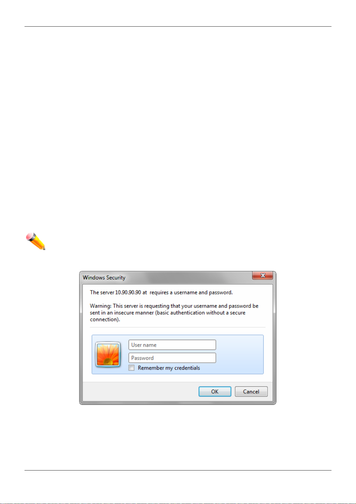
This opens the management module's user authentication window, as seen below.
Figure 1-1 Enter Network Password w ind ow
Leave both the User Name field and the Password field blank and click OK. This will open the Web-based user
interface. The Switch management features available in the web-based manager are explained below.
2
Page 11

xStack® DES-3200 Series Layer 2 Managed Fast Ethernet Switch
Web-based User Interface
The user interface provides access to various Switch configuration and management windows, allows you to view
performance statistics, and permits you to graphically monitor the system status.
Areas of the User Interface
The figure below shows the user interface. Three distinct areas divide the user interface, as described in the table.
AREA 2
AREA 1
Area
Number
Area 1
Area 2
AREA 3
Figure 1-2 Main Web-Manager page
Function
Select the menu or window to display. Open folders and click the hyperlinked menu buttons
and subfolders contained within them to display menus. Click the D-Link logo to go to the DLink website.
Presents a graphical near real-time image of the front panel of the Switch. This area displays
the Switch's ports, console and management port, showing port activity.
Some management functions, including save, reboot, download and upload are accessible
here.
Area 3
Presents switch information based on user selection and the entry of configuration data.
3
Page 12

xStack® DES-3200 Series Layer 2 Managed Fast Ethernet Switch
Web Pages
When connecting to the management mode of the Switch with a web browser, a login screen is displayed. Enter a
user name and password to access the Switch's management mode.
Below is a list of the main folders available in the Web interface:
System Configuration - In this section the user will be able to configure features regarding the Switch’s
configuration.
Management - In this section the user will be able to configure features regarding the Switch’s management.
L2 Features - In this section the user will be able to configure features regarding the Layer 2 functionality of the
Switch.
L3 Features - In this section the user will be able to configure features regarding the Layer 3 functionality of the
Switch.
QoS - In this section the user will be able to configure features regarding the Quality of Service functionality of the
Switch.
ACL - In this section the user will be able to configure features regarding the Access Control List functionality of the
Switch.
Security - In this section the user will be able to configure features regarding the Switch’s security.
Network Application - In this section the user will be able to configure features regarding network applications
handled by the Switch.
OAM - In this section the user will be able to configure features regarding the Switch’s operations, administration
and maintenance (OAM).
Monitoring - In this section the user will be able to monitor the Switch’s configuration and statistics.
NOTE: Be sure to configure the user name and password in the User Accounts menu before
connecting the Switch to the greater network.
4
Page 13

xStack® DES-3200 Series Layer 2 Managed Fast Ethernet Switch
Chapter 2 System Configuration
Device Information
System Information Settings
Port Configuration
PoE
Serial Port Settings
Warning Temperature Settings
System Log configuration
Time Range Settings
Time Settings
User Accounts Settings
Command Logging Settings
Device Information
This window contains the main settings for all the major functions for the Switch. It appears automatically when you
log on to the Switch. To return to the Device Information window after viewing other windows, click the DES-3200
Series link.
The Device Information window shows the Switch’s MAC Address (assigned by the factory and unchangeable), the
Boot PROM Version, Firmware Version, Hardware Version, and many other important types of information. This is
helpful to keep track of PROM and firmware updates and to obtain the Switch’s MAC address for entry into another
network device’s address table, if necessary. In addition, this window displays the status of functions on the Switch
to quickly assess their current global status.
Many functions are hyper-linked for easy access to enable quick configuration from this window.
Click the Settings
Figure 2-1 Device Information window
link to navigate to the appropriate feature page for configuration.
5
Page 14

xStack® DES-3200 Series Layer 2 Managed Fast Ethernet Switch
System Information Settings
The user can enter a System Name, System Location, and System Contact to aid in defining the Switch.
To view the following window, click System Configuration > System Information Settings, as show below:
Figure 2-2 System Information Settings window
The fields that can be configured are described below:
Parameter Description
System Name
System Location
System Contact
Click the Apply button to implement changes made.
Enter a system name for the Switch, if so desired. This name will identify it in the
Switch network.
Enter the location of the Switch, if so desired.
Enter a contact name for the Switch, if so desired.
Port Configuration
DDM
This folder contains windows that perform Digital Diagnostic Monitoring (DDM) functions on the Switch. Th ere are
windows that allow the user to view the digital diagnostic monitoring status of SFP modules inserting to the Switch
and to configure alarm settings, warning settings, temperature threshold settings, voltage threshold settings, bias
current threshold settings, Tx power threshold settings, and Rx power threshold settings.
DDM Settings
The window is used to configure the action that will occur for specific ports when an exceeding alarm thre shold or
warning threshold event is encountered.
To view the following window, click System Configuration > Port Configuration > DDM > DDM Settings, as
show below:
6
Page 15

xStack® DES-3200 Series Layer 2 Managed Fast Ethernet Switch
Figure 2-3 DDM Settings window
The fields that can be configured are described below:
Parameter Description
Trap State
Log State
From Port / To Port
State
Shutdown
Click the Apply button to accept the changes made for each individual section.
Specify whether to send the trap, when the operating parameter exceeds the alarm or
warning threshold.
Specify whether to send the log, when the operating parameter exceeds the alarm or
warning threshold.
Select a range of ports to be configured.
Use the drop-down menu to enable or disable the DDM state.
Specify whether to shutdown the port, when the operating parameter exceeds the Alarm
or Warning threshold.
Alarm - Shutdown the port when the configured alarm threshold range is exceeded.
Warning - Shutdown the port when the configured warning threshold range is exceeded.
None - The port will never shutdown regardless if the threshold ranges are exceeded or
not. This is the default.
DDM Temperature Threshold Settings
This window is used to configure the DDM Temperature Threshold Settings for specific ports on the Switch.
To view the following window, click System Configuration > Port Configuration > DDM > DDM Temperatur e
Threshold Settings, as show below:
7
Page 16

xStack® DES-3200 Series Layer 2 Managed Fast Ethernet Switch
Figure 2-4 DDM Temperature Threshold Settings window
The fields that can be configured are described below:
Parameter Description
From Port / To Port
High Alarm (-128-
127.996)
Low Alarm (-128-
127.996)
High Warning (-128-
127.996)
Low Warning (-128-
127.996)
Click the Apply button to accept the changes made.
Select a range of ports to be configured.
This is the highest threshold for the alarm. When the operating parameter rises above
this value, action associated with the alarm will be taken.
This is the lowest threshold for the alarm. When the operating parameter falls below this
value, action associated with the alarm will be taken.
This is the highest threshold for the warning. When the operating parameter rises above
this value, action associated with the warning will be taken.
This is the lowest threshold for the warning. When the operating parameter falls below
this value, action associated with the warning will be taken.
DDM Voltage Threshold Settings
This window is used to configure the DDM Voltage Threshold Settings for specific ports on the Switch.
To view the following window, click System Configuration > Port Configuration > DDM > DDM Voltage
Threshold Settings, as show below:
8
Page 17

xStack® DES-3200 Series Layer 2 Managed Fast Ethernet Switch
Figure 2-5 DDM Voltage Threshold Settings window
The fields that can be configured are described below:
Parameter Description
From Port / To Port
High Alarm (0-6.55)
Low Alarm (0-6.55)
High Warning (0-
6.55)
Low Warning (0-
6.55)
Click the Apply button to accept the changes made.
Select a range of ports to be configured.
This is the highest threshold for the alarm. When the operating parameter rises above
this value, action associated with the alarm will be taken.
This is the lowest threshold for the alarm. When the operating parameter falls below this
value, action associated with the alarm will be taken.
This is the highest threshold for the warning. When the operating parameter rises above
this value, action associated with the warning will be taken.
This is the lowest threshold for the warning. When the operating parameter falls below
this value, action associated with the warning will be taken.
DDM Bias Current Threshold Settings
This window is used to configure the threshold of the bias current for specific ports on the Switch.
To view the following window, click System Configuration > Port Configuration > DDM > DDM Bias Current
Threshold Settings, as show below:
9
Page 18

xStack® DES-3200 Series Layer 2 Managed Fast Ethernet Switch
Figure 2-6 DDM Bias Current Threshold Settings window
The fields that can be configured are described below:
Parameter Description
From Port / To Port
High Alarm (0-131)
Low Alarm (0-131)
High Warning (0-131)
Low Warning (0-131)
Click the Apply button to accept the changes made.
Select a range of ports to be configured.
This is the highest threshold for the alarm. When the operating parameter rises above
this value, action associated with the alarm will be taken.
This is the lowest threshold for the alarm. When the operating parameter falls below
this value, action associated with the alarm will be taken.
This is the highest threshold for the warning. When the operating parameter rises
above this value, action associated with the warning will be taken.
This is the lowest threshold for the warning. When the operating parameter falls below
this value, action associated with the warning will be taken.
DDM TX Power Threshold Settings
This window is used to configure the threshold of Tx power for specific ports on the Switch.
To view the following window, click System Configuration > Port Configuration > DDM > DDM TX Power
Threshold Settings, as show below:
10
Page 19

xStack® DES-3200 Series Layer 2 Managed Fast Ethernet Switch
Figure 2-7 DDM TX Power Threshold Settings window
The fields that can be configured are described below:
Parameter Description
From Port / To Port
High Alarm (0-
6.5535)
Low Alarm (0-
6.5535)
High Warning (0-
6.5535)
Low Warning (0-
6.5535)
Click the Apply button to accept the changes made.
Select a range of ports to be configured.
This is the highest threshold for the alarm. When the operating parameter rises above
this value, action associated with the alarm will be taken.
This is the lowest threshold for the alarm. When the operating parameter falls below this
value, action associated with the alarm will be taken.
This is the highest threshold for the warning. When the operating parameter rises above
this value, action associated with the warning will be taken.
This is the lowest threshold for the warning. When the operating parameter falls below
this value, action associated with the warning will be taken.
DDM RX Power Threshold Settings
This window is used to configure the threshold of RX power for specific ports on the Switch.
To view the following window, click System Configuration > Port Configuration > DDM > DDM RX Power
Threshold Settings, as show below:
11
Page 20

xStack® DES-3200 Series Layer 2 Managed Fast Ethernet Switch
Figure 2-8 DDM RX Power Threshold Settings window
The fields that can be configured are described below:
Parameter Description
From Port / To Port
High Alarm (0-
6.5535)
Low Alarm (0-
6.5535)
High Warning (0-
6.5535)
Low Warning (0-
6.5535)
Click the Apply button to accept the changes made.
Select a range of ports to be configured.
This is the highest threshold for the alarm. When the operating parameter rises above
this value, action associated with the alarm will be taken.
This is the lowest threshold for the alarm. When the operating parameter falls below this
value, action associated with the alarm will be taken.
This is the highest threshold for the warning. When the operating parameter rises above
this value, action associated with the warning will be taken.
This is the lowest threshold for the warning. When the operating parameter falls below
this value, action associated with the warning will be taken.
DDM Status Table
This window is used to display the current operating digital diagnostic monitoring parameters and their values on
the SFP module for specified ports.
To view the following window, click System Configuration > Port Configuration > DDM > DDM Status Table, as
show below:
12
Page 21

xStack® DES-3200 Series Layer 2 Managed Fast Ethernet Switch
Figure 2-9 DDM Status Table window
Port Settings
This page used to configure the details of the switch ports.
To view the following window, click System Configuration > Port Configuration > Port Settings, as show below:
13
Page 22

xStack® DES-3200 Series Layer 2 Managed Fast Ethernet Switch
Figure 2-10 Port Settings window
To configure switch ports:
1. Choose the port or sequential range of ports using the From Port and To Port drop-down menus.
2. Use the remaining drop-down menus to configure the parameters describ ed below:
The fields that can be configured are described below:
Parameter Description
From Port / To Port
State
Speed/Duplex
Select the appropriate port range used for the configuration here.
Toggle the State field to either enable or disable a given port or group of ports.
Toggle the Speed/Duplex field to select the speed and full-duplex/half-duplex state of the
port. Auto denotes auto-negotiation among 10, 100 and 1000 Mbps devices, in full- or
half-duplex (except 1000 Mbps which is always full duplex). The Auto setting allows the
port to automatically determine the fastest settings the device the port is connected to
can handle, and then to use those settings. The other options are 10M Half, 10M Full,
100M Half, 100M Full, 1000M Full_Master, and 1000M Full_Slave. There is no automatic
adjustment of port settings with any option other than Auto.
The Switch allows the user to configure three types of gigabit connections; 1000M
Full_Master, and 1000M Full_Slave. Gigabit connections only support full duplex
connections and take on certain characteristics that are different from the other choices
listed.
The 1000M Full_Master and 1000M Full_Slave parameters refer to connections running
a 1000BASE-T cable for connection between the Switch port and other device capable
of a gigabit connection. The master setting (1000M Full_Master) will allow the port to
advertise capabilities related to duplex, speed and physical layer type. The master
setting will also determine the master and slave relationship between the two connected
physical layers. This relationship is necessary for establishing the timing control between
the two physical layers. The timing control is set on a master physical layer by a local
source. The slave setting (1000M Full_Slave) uses loop timing, where the timing comes
from a data stream received from the master. If one connection is set for 1000M
Full_Master, the other side of the connection must be set for 1000M Full_Slave. Any
other configuration will result in a link down status for both ports.
Flow Control
Displays the flow control scheme used for the various port configurations. Ports
configured for full-duplex use 802.3x flow control, half-duplex ports use backpressure
flow control, and Auto ports use an automatic selection of the two. The default is
Disabled.
Address Learning
Enable or disable MAC address learning for the selected ports. When Enabled,
destination and source MAC addresses are automatically listed in the forwarding table.
When address learning is Disabled, MAC addresses must be manually entered into the
forwarding table. This is sometimes done for reasons of security or efficiency. See the
section on Forwarding/Filtering for information on entering MAC addresses into the
forwarding table. The default setting is Enabled.
MDIX
Auto - Select auto for auto sensing of the optimal type of cabling.
Normal - Select normal for normal cabling. If set to normal state, the port is in MDI mode
and can be connected to a PC NIC using a straight-through cable or a port (in MDI
mode) on another switch through a cross-over cable.
Cross - Select cross for cross cabling. If set to cross state, the port is in MDIX mode, and
can be connected to a port (in MDI mode) on another switch through a straig ht cable.
Medium Type
If configuring the Combo ports, this defines the type of transport medium to be used.
Click the Apply button to implement changes made.
Click the Refresh button to refresh the display section of this page.
14
Page 23

xStack® DES-3200 Series Layer 2 Managed Fast Ethernet Switch
Port Description Settings
The Switch supports a port description feature where the user may name various ports.
To view the following window, click System Configuration > Port Configuration > Port Description Settings, as
show below:
Figure 2-11 Port Description Settings window
The fields that can be configured are described below:
Parameter Description
From Port / To Port
Medium Type
Description
Click the Apply button to implement changes made.
Select the appropriate port range used for the configuration here.
Specify the medium type for the selected ports. If configuring the Combo ports, the
Medium Type defines the type of transport medium to be used, whether Copper or Fiber.
Users may then enter a description for the chosen port(s).
Port Error Disabled
The following window displays the information about ports that have been disconnected by the Switch when a
packet storm occurs or a loop was detected.
To view the following window, click System Configuration > Port Configuration > Port Error Disabled, as show
below:
Figure 2-12 Port Error Disabled
15
Page 24

xStack® DES-3200 Series Layer 2 Managed Fast Ethernet Switch
The fields that can be displayed are described below:
Parameter Description
Port
Port State
Connection Status
Reason
Display the port that has been error disabled.
Describe the current running state of the port, whether enabled or disabled.
Display the uplink status of the individual ports, whether enabled or disabled.
Describe the reason why the port has been error-disabled, such as it has become a
shutdown port for storm control.
Jumbo Frame Settings
The Switch supports jumbo frames. Jumbo frames are Ethernet frames with more than 1,518 bytes of payload. The
Switch supports jumbo frames with a maximum frame size of up to 12,228 bytes.
To view the following window, click System Configuration > Port Configuration > Jumbo Frame Settings, as
show below:
Figure 2-13 Jumbo Frame Settings window
The fields that can be configured are described below:
Parameter Description
Jumbo Frame
Click the Apply button to implement changes made.
Use the radio buttons to enable or disable the Jumbo Frame function on the Switch. The
default is Disabled. When disabled, the maximum frame size is 1,536 bytes. When
enabled, the maximum frame size is 12,228 bytes.
PoE
The DES-3200-28P and DES-3200-52P switches support Power over Ethernet (PoE) as defined by the IEEE
802.3af and 802.3at standard. Ports 1 to 24 for DES-3200-28P and ports 1 to 48 for DES-3200-52P can supply
about 48 VDC power to Powered Devices (PDs) over Category 5 or Category 3 UTP Ethernet cables.
The Switch follows the standard Power Sourcing Equipment (PSE) pinout Alternative A, whereby power is sent out
over pins 1, 2, 3 and 6. The Switches work with all D-Link 802.3af capable devices.
Pin Alternative
1 Negative Vport
2 Negative Vport
3 Positive Vport
4
5
6 Positive Vport
7
8
The Switch includes the following PoE features:
Auto-discovery recognizes the connection of a Powered Device (PD) and automatically sends power to it.
16
Page 25

xStack® DES-3200 Series Layer 2 Managed Fast Ethernet Switch
The Auto-disable function will activate when the port current value exceeds 350mA or when a short
happens.
For 802.3af capable devices, evaluate the table below, containing the correct power level per class and their
respective usage options.
Class Usage Minimum output power levels of PSE devices
0 Default 15.4 Watt
1 Optional 4.0 Watt
2 Optional 7.0 Watt
3 Optional 15.4 Watt
4 Reserved Treat as Class 0
For 802.3at capable devices, evaluate the table below, containing the correct power level per class and their
respective usage options. This feature provides power allocation of 0.1 Watt granularity, using the LLDP method.
Class Usage Minimum output power levels of PSE devices
0 Default 15.4 Watt
1 Optional 4.0 Watt
2 Optional 7.0 Watt
3 Optional 15.4 Watt
4 Optional 15.4 or 30 Watt
NOTE: Class 4 devices use the following equation:
Ptype=Icable x V Port_PSE min
To configure the PoE features on the Switch, click System Configuration > PoE.
Type 1 = 15.4 Watt.
Type 2 = 30 Watt.
PoE System Settings
This window is used to assign a power limit and power disconnect method for the whole PoE system. When the
total consumed power exceeds the power limit configured in this window, the PoE controller (located in the PSE)
disconnects the power to prevent overloading the power supply.
To view the following window, click System Configuration > PoE > PoE System Settings, as show below:
17
Page 26

xStack® DES-3200 Series Layer 2 Managed Fast Ethernet Switch
Figure 2-14 PoE System Settings window
The following parameters can be configured:
Parameter Description
Power Limit
Power Disconnect
Method
Legacy PD
Click Apply to implement changes made.
Sets the limit of power to be used from the Switch’s power source to PoE ports. The user
may configure a Power Limit between 37W and 188W for the DES-3200-28P, and
between 37W and 370W for DES-3200-52P.
The PoE controller uses either Deny Next Port or Deny Low Priority Port to offset the
power limit being exceeded and keeps the Switch’s power at a usable level. Use the drop
down menu to select a Power Disconnect Method. The default Power Disconnect
Method is Deny Next Port. Both Power Disconnection Methods are described below:
Deny Next Port – After the power limit has been exceeded, the next port attempting to
power up is denied, regardless of its priority. If Power Disconnection Method is set to
Deny Next Port, the system cannot utilize out of its maximum power capacity. The
maximum unused watt is 19W.
Deny Low Priority Port – After the power limit has been exceeded, the next port
attempting to power up causes the port with the lowest priority to shut down so as to
allow the high-priority and critical priority ports to power up.
Use the drop-down menu to enable or disable detecting legacy PDs signal.
PoE Port Settings
To view the following window, click System Configuration > PoE > PoE Port Settings, as show below:
18
Page 27

xStack® DES-3200 Series Layer 2 Managed Fast Ethernet Switch
Figure 2-15 PoE Port Settings window
The following parameters can be configured:
Parameter Description
From Port / To Port
State
Time Range
Priority
Power Limit
Select a range of ports from the drop-down menus to be enabled or disabled for PoE.
Use the drop-down menu to enable or disable ports for PoE.
Select a range of the time to the port set as POE. If Time Range is configured, the power
can only be supplied during the specified period of time.
Use the drop-down menu to select the priority of the PoE ports. Port priority determines
the priority which the system attempts to supply the power to the ports. There are three
levels of priority that can be selected, Critical, High, and Low. When multiple ports
happen to have the same level of priority, the port ID will be used to determine the
priority. The lower port ID has higher priority. The setting of priority will affect the order of
supplying power. Whether the disconnect method is set to deny low priority port, the
priority of each port will be used by the system to manage the supply of power to ports.
This function is used to configure the per-port power limit. If a port exceeds its power
limit, it will shut down.
For 802.3af capable devices, the minimum output power levels of PSE devices for each
class is:
Class 0 – 15.4 Watt
Class 1 – 4.0 Watt
Class 2 – 7.0 Watt
Class 3 – 15.4 Watt
Class 4 – Treat as Class 0
For 802.3at capable devices with power allocation of 0.1 Watt granularity, using the
LLDP method, the minimum output power levels of PSE devices for each class is:
Class 0 – 15.4 Watt
Class 1 – 4.0 Watt
Class 2 – 7.0 Watt
Class 3 – 15.4 Watt
Class 4 – 15.4 or 30 Watt
19
Page 28

xStack® DES-3200 Series Layer 2 Managed Fast Ethernet Switch
The following is the power limit applied to the port for these five classes. For each class,
the power limit is a little more than the power consumption range for that class. This
takes into account any power loss on the cable. Thus, the following are the typical
values:
Class 0 – 16200mW
Class 1 – 4200mW
Class 2 – 7400mW
Class 3 – 16200mW
User Define – 1000 to 35000mW
Click Apply to implement changes made. The port status of all PoE configured ports is displayed in the table in the
bottom half of the screen shown above.
Serial Port Settings
This window allows the user to adjust the Baud Rate and the Auto Logout values.
To view the following window, click System Configuration > Serial Port Settings, as show below:
Figure 2-16 Serial Port Settings window
The fields that can be configured or displayed are described below:
Parameter Description
Baud Rate
Auto Logout
Data Bits
Parity Bits
Stop Bits
Click the Apply button to implement changes made.
Specify the baud rate for the serial port on the Switch. There are four possible baud rates to
choose from, 9600, 19200, 38400 and 115200. For a connection to the Switch using the
console port, the baud rate must be set to 115200, which is the default setting.
Select the logout time used for the console interface. This automatically logs the user out
after an idle period of time, as defined. Choose from the following options: 2, 5, 10, 15
minutes or Never. The default setting is 10 minutes.
Display the data bits used for the serial port connection.
Display the parity bits used for the serial port connection.
Display the stop bits used for the serial port connection.
Warning Temperature Settings
This window allows the user to configure the system warning temperature parameters.
To view the following window, click System Configuration > Warning Temperature Settings, as show below:
20
Page 29

xStack® DES-3200 Series Layer 2 Managed Fast Ethernet Switch
Figure 2-17 Warning Temperature Settings window
The fields that can be configured are described below:
Parameter Description
Traps State
Log State
High Threshold
(-500-500)
Low Threshold
(-500-500)
Click the Apply button to implement changes made.
Use the drop-down menu to enable or disable the traps state option of the warning
temperature setting.
Use the drop-down menu to enable or disable the log state option of the warning
temperature setting.
Enter the high threshold value of the warning temperature setting.
Enter the low threshold value of the warning temperature setting.
System Log Configuration
System Log Settings
The Switch allows users to choose a method for which to save the switch log to the flash memory of the Switch.
To view the following window, click System Configuration > System Log Configuration > System Log Setting s,
as show below:
Figure 2-18 System Log Settings window
The fields that can be configured are described below:
Parameter Description
System Log
Save Mode
Use the radio buttons to enable or disable the system log settings.
Use the drop-down menu to choose the method for saving the switch log to the flash memory.
The user has three options:
On Demand – Users who choose this method will only save log files when they manually tell
the Switch to do so, either using the Save Log link in the Save folder.
Time Interval – Users who choose this method can configure a time interval by which the
Switch will save the log files, in the box adjacent to this configuration field. The user may set
a time between 1 and 65535 minutes.
Log Trigger – Users who choose this method will have log files saved to the Switch every
time a log event occurs on the Switch.
21
Page 30

xStack® DES-3200 Series Layer 2 Managed Fast Ethernet Switch
Click the Apply button to accept the changes made for each individual section.
System Log Server Settings
The Switch can send System log messages to up to four designated servers using the System Log Server.
To view the following window, click System Configuration > System Log Configuration > System Log Server
Settings, as show below:
Figure 2-19 System Log Server Settings
The fields that can be configured are described below:
Parameter Description
Server ID
Severity
Server IPv4 Address
Facility
UDP Port (514 or
6000-65535)
Status
Click the Apply button to accept the changes made.
Click the Edit button to re-configure the specific entry.
Click the Delete button to remove the specific entry.
Click the Delete All button to remove all servers configured.
Syslog server settings index (1 to 4).
Use the drop-down menu to select the higher level of messages that will be sent. All
messages which level is higher than selecting level will be sent. The options are
Emergency, Alert, Critical, Error, Warning, Notice, Informational and Debug.
The IPv4 address of the Syslog server.
Use the drop-down menu to select Local 0, Local 1, Local 2, Local 3, Local 4, Local 5,
Local 6, or Local 7.
Type the UDP port number used for sending Syslog messages. The default is 514.
Choose Enabled or Disabled to activate or deactivate.
System Log
Users can view and delete the local history log as compiled by the Switch's management agent.
To view the following window, click System Configuration > System Log Configuration > System Log, as show
below:
22
Page 31

xStack® DES-3200 Series Layer 2 Managed Fast Ethernet Switch
Figure 2-20 System Log window
The fields that can be configured or displayed are described below:
Parameter Description
Log Type
Index
Time
Level
Log Text
Click the Find button to display the log in the display section according to the selection made.
Click the Clear Log button to clear the entries from the log in the display section.
Click the Clear Attack Log button to clear the entries from the attack log in the display section.
The Switch can record event information in its own log. Click Go to go to the next page of the System Log window.
In the drop-down menu the user can select the log type that will be displayed.
Severity - When selecting Severity from the drop-down menu, a secondary tick must be
made. Secondary ticks are Emergency, Alert, Critical, Error, Warning, Notice,
Informational and Debug. To view all information in the log, simply tick the All check box.
Module List - When selecting Module List, the module name must be manu ally entered.
Available modules are MSTP, ERROR_LOG and ERPS.
Attack Log - When selecting Attack Log all attacks will be listed.
A counter incremented whenever an entry to the Switch's history log is made. The table
displays the last entry (highest sequence number) first.
Display the time in days, hours, minutes, and seconds.
Display the level of the log entry.
Display text describing the event that triggered the history log entry.
System Log & Trap Settings
The Switch allows users to configure the system log source IP interface addresses here.
To view the following window, click System Configuration > System Log Configuration > System Log & Trap
Settings, as show below:
Figure 2-21 System Log & Trap Settings window
The fields that can be configured are described below:
23
Page 32

xStack® DES-3200 Series Layer 2 Managed Fast Ethernet Switch
Parameter Description
Interface Name
IPv4 Address
Click the Apply button to accept the changes made for each individual section.
Click the Clear button to clear all the information entered in the fields.
Enter the IP interface name used.
Enter the IPv4 address used.
System Severity Settings
The Switch can be configured to allow alerts be logged or sent as a trap to an SNMP agent. The level at which the
alert triggers either a log entry or a trap message can be set as well. Use the System Severity Settings window to
set the criteria for alerts. The current settings are displayed below the System Severity Table.
To view the following window, click System Configuration > System Log Configuration > System Severity
Settings, as show below:
Figure 2-22 System Severity Settings window
The fields that can be configured are described below:
Parameter Description
System Severity
Severity Level
Click the Apply button to accept the changes made.
Choose how the alerts are used from the drop-down menu. Select Log to send the alert of
the Severity Type configured to the Switch’s log for analysis. Choose Trap to send it to an
SNMP agent for analysis, or select All to send the chosen alert type to an SNMP agent and
the Switch’s log for analysis.
This drop-down menu allows you to select the level of messages that will be sent. The
options are Emergency (0), Alert (1), Critical (2), Error (3), Warning (4), Notice (5),
Information (6) and Debug (7).
Time Range Settings
Time range is a time period that the respective function will take an effect on, such as ACL. For example, the
administrator can configure the time-based ACL to allow users to surf the Internet on every Saturday and every
Sunday, meanwhile to deny users to surf the Internet on weekdays.
The user may enter up to 64 time range entries on the Switch.
To view the following window, click System Configuration > Time Range Settings, as show below:
Figure 2-23 Time Range Settings window
24
Page 33

xStack® DES-3200 Series Layer 2 Managed Fast Ethernet Switch
The fields that can be configured are described below:
Parameter Description
Range Name
Hours (HH MM
SS)
Weekdays
Click the Apply button to accept the changes made. Current configured entries will be displayed in the Time
Range Information table in the bottom half of the window shown above.
Enter a name of no more than 32 alphanumeric characters that will be used to identify this
time range on the Switch. This range name will be used in the Access Profile table to
identify the access profile and associated rule to be enabled during this time range.
This parameter is used to set the time in the day that this time range is to be enabled using
the following parameters:
Start Time - Use this parameter to identify the starting time of the time range, in hours,
minutes and seconds, based on the 24-hour time system.
End Time - Use this parameter to identify the ending time of the time range, in hours,
minutes and seconds, based on the 24-hour time system.
Use the check boxes to select the corresponding days of the week that this time range is to
be enabled. Tick the Select All Days check box to configure this time range for every day of
the week.
Time Settings
Users can configure the time settings for the Switch.
To view the following window, click System Configuration > Time Settings, as show below:
Figure 2-24 Time Settings window
The fields that can be configured are described below:
Parameter Description
Date (DD / MM / YYYY)
Time (HH:MM:SS)
Click the Apply button to accept the changes made.
Enter the current day, month, and year to update the system clock.
Enter the current time in hours, minutes, and seconds.
User Accounts Settings
The Switch allows the control of user privileges.
To view the following window, click System Configuration > User Accounts Settings, as show below:
25
Page 34

xStack® DES-3200 Series Layer 2 Managed Fast Ethernet Switch
Figure 2-25 User Accounts Settings window
To add a new user, type in a User Name and New Password and retype the same password in the Confirm New
Password field. Choose the level of privilege (Admin, Operator, Power User or User) from the Access Right dropdown menu.
Management Admin Operator Power User User
Configuration Read/Write Read/Write–
partly
Network Monitoring Read/Write Read/Write Read-only Read-only
Community Strings and Trap
Stations
Update Firmware and
Configuration Files
System Utilities Read/Write Read-only Read-only Read-only
Factory Reset Read/Write No No No
User Account Management
Add/Update/Delete User Accounts Read/Write No No No
View User Accounts Read/Write No No No
The fields that can be configured are described below:
Parameter Description
Read/Write Read-only Read-only Read-only
Read/Write Read/Write No No
Read/Write–
partly
No
User Name
Password
Confirm Password
Access Right
Encryption
Click the Apply button to accept the changes made.
NOTICE: In case of lost passwords or password corruption, please refer to the appendix chapter
NOTE: The username and password should be less than 16 characters.
Enter a new user name for the Switch.
Enter a new password for the Switch.
Re-type in a new password for the Switch.
Specify the access right for this user.
Specifies that encryption will be applied to this account. Option to choose from are Plain
Text, and SHA-1.
entitled, “Password Recovery Procedure,” which will guide you through the steps necessary
to resolve this issue.
Command Logging Settings
This window is used to enable or disable the command logging settings.
26
Page 35

xStack® DES-3200 Series Layer 2 Managed Fast Ethernet Switch
To view this window, click System Configuration > Command Logging Settings, as shown below:
Figure 2-26 Command Logging Settings window
The fields that can be configured are described below:
Parameter Description
Command Logging State
Use the radio buttons to enable or disable the function.
Click the Apply button to accept the changes made.
NOTE: When the switch is under the booting procedure, all configuration commands will not be
logged. When the user uses AAA authentication to logged in, the user name should not be
changed if the user has used the Enable Admin function to replace its privilege.
27
Page 36

xStack® DES-3200 Series Layer 2 Managed Fast Ethernet Switch
Chapter 3 Management
ARP
Gratuitous ARP
IPv6 Neighbor Settings
IP Interface
Management Settings
Session Table
Single IP Management
SNMP Settings
Telnet Settings
Web Settings
ARP
Static ARP Settings
The Address Resolution Protocol is a TCP/IP protocol that converts IP addresses into physical addresses. This
table allows network managers to view, define, modify, and delete ARP information for specific devices. Static
entries can be defined in the ARP table. When static entries are defined, a permanent entry is entered and is used
to translate IP addresses to MAC addresses.
To view the following window, click Management > ARP > Static ARP Settings, as show below:
Figure 3-1 Static ARP Settings window
The fields that can be configured are described below:
Parameter Description
ARP Aging Time (0-65535)
IP Address
MAC Address
Click the Apply button to accept the changes made for each individual section.
Click the Delete All button to remove all the entries listed.
Click the Edit button to re-configure the specific entry.
Click the Delete button to remove the specific entry.
The ARP entry age-out time, in minutes. The default is 20 minutes.
The IP address of the ARP entry.
The MAC address of the ARP entry.
ARP Table
Users can display current ARP entries on the Switch.
To view the following window, click Management > ARP > ARP Table, as show below:
28
Page 37

xStack® DES-3200 Series Layer 2 Managed Fast Ethernet Switch
Figure 3-2 ARP Table window
The fields that can be configured are described below:
Parameter Description
Interface Name
IP Address
MAC Address
Click the Find button to locate a specific entry based on the information entered.
Click the Show Static button to display only the static entries in the display table.
Click the Clear All button to remove all the entries listed in the table.
Enter a page number and click the Go button to navigate to a specific page when multiple pages exist.
Enter or view the Interface name used.
Enter or view the IP Address used.
Enter or view the MAC Address used.
Gratuitous ARP
Gratuitous ARP Global Settings
The user can enable or disable the gratuitous ARP global settings here.
To view the following window, click Management > Gratuitous ARP > Gratuitous ARP Global Settings, as show
below:
Figure 3-3 Gratuitous ARP Global Settings Window
The fields that can be configured are described below:
Parameter Description
Send On IP Interface
Status Up
Send On Duplicate IP
Detected
The command is used to enable/disable sending of gratuitous ARP request packet
while the IPIF interface become up. This is used to automatically announce the
interface’s IP address to other nodes. By default, the state is Enabled, and only one
gratuitous ARP packet will be broadcast.
The command is used to enable/disable the sending of gratuitous ARP request
packet while a duplicate IP is detected. By default, the state is Enabled. For this
command, the duplicate IP detected means that the system received an ARP request
packet that is sent by an IP address that match the system’s own IP address. In this
case, the system knows that somebody out there uses an IP address that is conflict
29
Page 38

xStack® DES-3200 Series Layer 2 Managed Fast Ethernet Switch
with the system. In order to reclaim the correct host of this IP address, the system can
send out the gratuitous ARP request packets for this duplicate IP address.
Gratuitous ARP
Learning
Click the Apply button to accept the changes made.
NOTE: With the gratuitous ARP learning, the system will not learn new entry but only do the update on
the ARP table based on the received gratuitous ARP packet.
Normally, the system will only learn the ARP reply packet or a normal ARP request
packet that asks for the MAC address that corresponds to the system’s IP address.
The command is used to enable/disable learning of ARP entry in ARP cache based
on the received gratuitous ARP packet. The gratuitous ARP packet is sent by a
source IP address that is identical to the IP that the packet is queries for. By default,
the state is Enabled.
Gratuitous ARP Settings
The user can configure the IP interface’s gratuitous ARP parameter.
To view the following window, click Management > Gratuitous ARP > Gratuitous ARP Settings, as show below:
Figure 3-4 Gratuitous ARP Settings window
The fields that can be configured are described below:
Parameter Description
Trap
Log
Interface Name
Interval Time (0-65535)
Click the Apply button to accept the changes made for each individual section.
Use the drop-down menu to enable or disable the trap option. By default the trap is
disabled.
Use the drop-down menu to enable or disable the logging option. By default the
event log is enabled.
Enter the interface name of the Layer 3 interface. Select All to enable or disable
gratuitous ARP trap or log on all interfaces.
Enter the periodically send gratuitous ARP interval time in seconds. 0 means that
gratuitous ARP request will not be sent periodically. By default the interval time is 0.
IPv6 Neighbor Settings
The user can configure the Switch’s IPv6 neighbor settings. The Switch’s current IPv6 neighbor settings will be
displayed in the table at the bottom of this window.
To view the following window, click Management > IPv6 Neighbor Settings, as show below:
30
Page 39

xStack® DES-3200 Series Layer 2 Managed Fast Ethernet Switch
Figure 3-5 IPv6 Neighbor Settings window
The fields that can be configured are described below:
Parameter Description
Interface Name
Neighbor IPv6 Address
Link Layer MAC
Address
Interface Name
State
Click the Add button to add a new entry based on the information entered.
Click the Find button to locate a specific entry based on the information entered.
Click the Clear button to clear all the information entered in the fields.
Enter the interface name of the IPv6 neighbor.
Enter the neighbor IPv6 address.
Enter the link layer MAC address.
Enter the name of the IPv6 neighbor. Tick the All check box to search for all current
interfaces on the Switch.
Use the drop-down menu to select All, Address, Static, or Dynamic. When the user
selects address from the drop-down menu, the user will be able to enter an IP
address in the space provided next to the state option.
IP Interface
System IP Address Settings
The IP address may initially be set using the console interface prior to connecting to it through the Ethernet. The
Web manager will display the Switch’s current IP settings.
NOTE: The Switch’s factory default IP address is 10.90.90.90 with a subnet mask of 255.0.0.0 and a
default gateway of 0.0.0.0.
31
Page 40

xStack® DES-3200 Series Layer 2 Managed Fast Ethernet Switch
To view the following window, click Management > IP Interface > System IP Address Settings, as show below:
Figure 3-6 System IP Address Settings window
The fields that can be configured are described below:
Parameter Description
Static
Allow the entry of an IP address, subnet mask, and a default gateway for the Switch.
These fields should be of the form xxx.xxx.xxx.xxx, where each xxx is a number
(represented in decimal form) between 0 and 255. This address should be a unique
address on the network assigned for use by the network administrator.
DHCP
The Switch will send out a DHCP broadcast request when it is powered up. The
DHCP protocol allows IP addresses, network masks, and default gateways to be
assigned by a DHCP server. If this option is set, the Switch will first look for a DHCP
server to provide it with this information before using the default or previously entered
settings.
BOOTP
The Switch will send out a BOOTP broadcast request when it is powered up. The
BOOTP protocol allows IP addresses, network masks, and default gateways to be
assigned by a central BOOTP server. If this option is set, the Switch will first look for a
BOOTP server to provide it with this information before using the default or previously
entered settings.
The following table will describe the fields that are about the System Interface.
Parameter Description
Interface Name
Management VLAN
Name
Display the System interface name.
This allows the entry of a VLAN name from which a management station will be
allowed to manage the Switch using TCP/IP (in-band via Web manager or Telnet).
Management stations that are on VLANs other than the one entered here will not be
able to manage the Switch in-band unless their IP addresses are entered in the
Trusted Host window (Security > Trusted Host). If VLANs have not yet been
configured for the Switch, the default VLAN contains all of the Switch’s ports. There
are no entries in the Trusted Host table, by default, so any management station that
can connect to the Switch can access the Switch until a management VLAN is
specified or Management Station IP addresses are assigned.
Interface Admin State
IP Address
Subnet Mask
Gateway
Use the drop-down menu to enable or disable the configuration on this interface. If
the state is disabled, the IP interface cannot be accessed.
This field allows the entry of an IPv4 address to be assigned to this IP interface.
A Bitmask that determines the extent of the subnet that the Switch is on. Should be of
the form xxx.xxx.xxx.xxx, where each xxx is a number (represented in decimal)
between 0 and 255. The value should be 255.0.0.0 for a Class A network,
255.255.0.0 for a Class B network, and 255.255.255.0 for a Class C network, but
custom subnet masks are allowed.
IP address that determines where packets with a destination address outside the
current subnet should be sent. This is usually the address of a router or a host acting
32
Page 41

xStack® DES-3200 Series Layer 2 Managed Fast Ethernet Switch
as an IP gateway. If your network is not part of an intranet, or you do not want the
Switch to be accessible outside your local network, you can leave this field
unchanged.
Click the Apply button to accept the changes made.
Interface Settings
Users can display the Switch’s current IP interface settings.
To view the following window, click Management > IP Interface > Interface Settings, as show below:
Figure 3-7 Interface Settings window
The fields that can be configured are described below:
Parameter Description
Interface Name
Click the Find button to locate a specific entry based on the information entered.
Click the Add button to add a new entry based on the information entered.
Click the Delete All button to remove all the entries listed.
Click the IPv4 Edit button to edit the IPv4 settings for the specific entry.
Click the IPv6 Edit button to edit the IPv6 settings for the specific entry.
Click the Delete button to remove the specific entry.
NOTE: To create IPv6 interfaces, the user has to create an IPv4 interface then edit it to IPv6.
Click the Add button to see the following window.
The fields that can be configured are described below:
Parameter Description
Enter the name of the IP interface to search for.
Figure 3-8 IPv4 Interface Settings window
Interface Name
IPv4 Address
Subnet Mask
VLAN Name
Enter the name of the IP interface being created.
Enter the IPv4 address used.
Enter the IPv4 subnet mask used.
Enter the VLAN Name used.
33
Page 42

xStack® DES-3200 Series Layer 2 Managed Fast Ethernet Switch
Interface Admin State
Use the drop-down menu to enable or disable the Interface Admin State.
Click the Apply button to accept the changes made.
Click the <<Back button to discard the changes made and return to the previous page.
Click the IPv4 Edit button to see the following window.
Figure 3-9 IPv4 Interface Settings – Edit window
The fields that can be configured are described below:
Parameter Description
Get IP From
Use the drop-down menu to specify the method that this Interface uses to acquire an
IP address.
Interface Name
IPv4 Address
Subnet Mask
VLAN Name
IPv4 State
Interface Admin State
DHCP Option 12 State
Enter the name of the IP interface being configured.
Enter the IPv4 address used.
Enter the IPv4 subnet mask used.
Enter the VLAN Name used.
Use the drop-down menu to enable or disable IPv4 State.
Use the drop-down menu to enable or disable the Interface Admin State.
Use the drop-down menu to enable or disable insertion of option 12 in the
DHCPDISCOVER and DHCPREQUEST message.
DHCP Option 12 Host
Name
Enter the host name to be inserted in the DHCPDISCOVER and DHCPREQUEST
message.
Click the Apply button to accept the changes made.
Click the <<Back button to discard the changes made and return to the previous page.
Click the IPv6 Edit button to see the following window.
Figure 3-10 IPv6 Interface Settings window
34
Page 43

xStack® DES-3200 Series Layer 2 Managed Fast Ethernet Switch
The fields that can be configured or displayed are described below:
Parameter Description
Interface Name
IPv6 State
Interface Admin State
IPv6 Network Address
NS Retransmit Time (0-
4294967295)
Automatic Link Local
Address
Click the Apply button to accept the changes made for each individual section.
Click the <<Back button to discard the changes made and return to the previous page.
Click the View All IPv6 Address
Click the View All IPv6 Address
Click the <<Back button to return to the previous page.
Display the IPv6 interface name.
Use the drop-down menu to enable or disable IPv6 State.
Use the drop-down menu to enable or disable the Interface Admin State.
Here the user can enter the IPv6 global or local link address.
Enter the Neighbor solicitation’s retransmit timer in millisecond here. It has the same
value as the RA retransmit time in the config ipv6 nd ra command. If this field is
configured, it will duplicate the entry into the RA field.
Here the user can select to enable or disable the Automatic Link Local Address.
link to view all the current IPv6 address.
link to see the following window.
Figure 3-11 IPv6 Interface Settings window
Management Settings
Users can stop the scrolling of multiple pages beyond the limits of the console when using the Command Line
Interface.
This window is also used to enable the DHCP auto configuration feature on the Switch. When enabled, the Switch
is instructed to receive a configuration file from a TFTP server, which will set the Switch to become a DHCP client
automatically on boot-up. To employ this method, the DHCP server must be set up to deliver the TFTP server IP
address and configuration file name information in the DHCP reply packet. The TFTP server must be up and
running and hold the necessary configuration file stored in its base directory when the request is received from the
Switch. For more information about loading a configuration file for use by a client, see the DHCP server and/or
TFTP server software instructions. The user may also consult the Upload Log File window description located in
the Tools section of this manual.
If the Switch is unable to complete the DHCP auto configuration, the previously saved configuration file present in
the Switch’s memory will be used.
Users can also configure Password Encryption on the Switch.
To view the following window, click Management > Management Settings, as show below:
35
Page 44

xStack® DES-3200 Series Layer 2 Managed Fast Ethernet Switch
Figure 3-12 Management Settings window
The fields that can be configured are described below:
Parameter Description
CLI Paging State
DHCP Auto
Configuration State
Autoconfig Timeout
(1-65535)
Password Encryption
State
Running
Configuration
Click the Apply button to accept the changes made.
To learn more about the D-Link Green Technologies, go to http://green.dlink.com/
Command Line Interface paging stops each page at the end of the console. This
allows you to stop the scrolling of multiple pages of text beyond the limits of the
console. CLI Paging is Enabled by default. To disable it, click the Disabled radio
button.
Enable or disable the Switch’s DHCP auto configuration feature. When enabled, the
Switch is instructed to receive a configuration file from a TFTP server, which will set
the Switch to become a DHCP client automatically on boot-up. To employ this
method, the DHCP server must be set up to deliver the TFTP server IP address and
configuration file name information in the DHCP reply packet. The TFTP server must
be up and running and hold the necessary configuration file stored in its base
directory when the request is received from the Switch.
Enter a time between 1 and 65535 for the auto-configuration timeout.
Password encryption will encrypt the password configuration in configuration files.
Password encryption is Disabled by default. To enable password encryption, click the
Enabled radio button.
Under the Password Recovery option, the running configuration can be enabled or
disable. Being enabled, will allow the user to perform a password recovery of the
running configuration.
for more details.
Session Table
Users can display the management sessions since the Switch was last rebooted.
To view the following window, click Management > Session Table, as show below:
Figure 3-13 Session Table window
Click the Refresh button to refresh the display table so that new entries will appear.
36
 Loading...