

Page 1
Version 1.0 | 9/27/13
User Manual
Wireless AC Day/Night Camera with Color Night Vision
DCS-2136L
Page 2
Preface
D-Link reserves the right to revise this publication and to make changes in the content hereof without obligation to notify any person or organization
of such revisions or changes. Information in this document may become obsolete as our services and websites develop and change. Please refer to
the www.mydlink.com website for the most current information.
Manual Revisions
Revision Date Description
1.0 September 27, 2013 • Initial release for Revision A1
Trademarks
D-Link and the D-Link logo are trademarks or registered trademarks of D-Link Corporation or its subsidiaries in the United States or other countries.
All other company or product names mentioned herein are trademarks or registered trademarks of their respective companies.
Copyright © 2013 D-Link Systems, Inc.
All rights reserved. This publication may not be reproduced, in whole or in part, without prior expressed written permission from D-Link Systems, Inc.
2D-Link DCS-2136L User Manual
Page 3

Table of Contents
Preface ................................................................................2
Manual Revisions .......................................................................... 2
Trademarks .....................................................................................2
Product Overview .............................................................. 4
Package Contents ......................................................................... 4
Minimum Requirements ............................................................ 5
Introduction ...................................................................................6
Features ............................................................................................7
Hardware Overview ..................................................................... 8
Front .......................................................................................... 8
Rear ............................................................................................ 9
Sides ........................................................................................10
Installation .......................................................................11
Wireless Installation Considerations ....................................11
Zero Conguration Setup ........................................................13
Camera Setup Wizard ................................................................16
Windows Users ....................................................................16
Mac Users...............................................................................17
Manual Hardware Installation ................................................18
WPS - Push Button Setup .........................................................19
Download mydlink Lite/mydlink + Apps ...........................20
Mount the Camera .....................................................................21
Image Setup .........................................................................36
Audio and Video ..................................................................38
Preset.......................................................................................40
Enable Motion Detection .................................................42
Time and Date ......................................................................43
Event Setup ...........................................................................44
SD Card ...................................................................................52
Advanced ......................................................................................53
Digital Input/Output .........................................................53
White Light LED ...................................................................54
HTTPS ......................................................................................55
Access List..............................................................................56
Maintenance ................................................................................57
Device Management .........................................................57
System ....................................................................................58
Firmware Upgrade ..............................................................59
Status ..............................................................................................60
Device Info ............................................................................60
Logs .........................................................................................61
Support ..................................................................................62
Troubleshooting ..............................................................63
DI/DO Specications ....................................................... 64
Conguration ...................................................................22
Conguration Interface ............................................................22
Live Video ......................................................................................23
Setup ...............................................................................................25
Setup Wizards ......................................................................25
Network Setup .....................................................................31
Wireless Setup ......................................................................34
Technical Specications .................................................. 65
Contacting Technical Support ........................................68
Warranty ........................................................................... 69
Registration .....................................................................76
3D-Link DCS-2136L User Manual
Page 4

Section 1: Product Overview
DCS-2136L Wireless AC Day/Night Camera with Color Night Vision
CAT5 Ethernet cable
Power adapter
Stand/Mounting Bracket
Product Overview
Package Contents
Quick Install Guide
If any of the above items are missing, please contact your reseller.
Note: Using a power supply with a dierent voltage rating than the one included with your DCS-2136L will cause damage and void the warranty
for this product.
4D-Link DCS-2136L User Manual
Page 5

Section 1: Product Overview
Network Requirements • 10/100 Ethernet network or an 802.11ac/n/g/b wireless network
Web-based Conguration Utility
Requirements
mydlink Website Requirements
Minimum Requirements
Browser Requirements:
• Internet Explorer 7
• Firefox 12
• Safari 4
• Chrome 20
Note: Make sure you have the latest version of Java installed.
Visit www.java.com to download the latest version.
• Broadband Internet connection
• Computer with:
• Internet Explorer 7 or higher (ActiveX)
• Firefox 12 or higher
• Safari 4 or higher
• Chrome 20 or higher
mydlink Mobile Requirements
• iOS version 4.3 or above
• Android version 2.1 or above
5D-Link DCS-2136L User Manual
Page 6

Section 1: Product Overview
Introduction
Congratulations on your purchase of the DCS-2136L Wireless AC Day/Night Camera with Color Night Vision. The DCS-2136L
is a versatile surveillance solution for your business, and it oers mydlink™ Cloud Services. Unlike a standard webcam, the
DCS-2136L is a complete system with a built-in CPU and web server that transmits high quality video images for surveillance.
The simple installation and intuitive web-based interface oer easy integration with your Ethernet/Fast Ethernet or 802.11ac/n/g
wireless network.
The DCS-2136L comes with remote monitoring and motion detection features, and can be controlled from any PC/Notebook
over your local network or through the Internet via a web browser. If you download the free mydlink Lite App, you can monitor
your business from anywhere, anytime from your iPhone, iPad or Android device, providing comprehensive and cost-eective
24/7 security.
6D-Link DCS-2136L User Manual
Page 7

Section 1: Product Overview
Features
Easy to Use
The DCS-2136L is a stand-alone surveillance camera that requires no special hardware or software. You can operate the camera independently,
even without a PC. Since the DCS-2136L is mydlink-enabled, you can either view and manage your camera using the mydlink website, or you can
use the mydlink mobile app for iOS and Android mobile devices.
Supports a Variety of Platforms
Supports TCP/IP networking, HTTP, and other Internet-related protocols. The DCS-2136L can also be integrated easily into other Internet/Intranet
applications because of its standards-based features.
Web Conguration
Using a standard Web browser, administrators can congure and manage the DCS-2136L directly from its own Web page via Intranet or Internet.
This means you can access your DCS-2136L anytime, from anywhere in the world.
All-Day Surveillance with low-light color image capability
A built-in white light LED lets you monitor an area 24 hours a day with full color images, even in areas with low light or complete darkness. Combined
with the passive IR sensor which can be used to trigger the white light LED, the DCS-2136L is a versatile surveillance device.
Broad Range of Applications
The DCS-2136L allows remote access using a Web browser for live image viewing, and allows the administrator to manage and control the
DCS-2136L anytime, from anywhere in the world. There are many applications for this, including industrial monitoring of oces, banks, hospitals,
and amusement parks, as well as educational monitoring of pre-schools, middle schools, and high schools.
802.11ac Wireless or Ethernet/Fast Ethernet Support
The DCS-2136L oers wireless 802.11ac and Ethernet/Fast Ethernet connectivity, making the DCS-2136L easy to integrate into your existing network
environment. The DCS-2136L works with 10/100/1000Mbps Ethernet based networks for traditional wired environments, and works with 802.11ac
routers or access points for added exibility. The Site Survey feature also allows you to view and connect to any available wireless network.
Remote Monitoring Utility
The D-ViewCam™ application adds enhanced features and functionality for the DCS-2136L. It allows administrators to congure and access the
DCS-2136L from a remote site via Intranet or Internet. Other features include image monitoring, recording images to a hard drive, taking snapshots,
and viewing up to 32 cameras on one screen.
7D-Link DCS-2136L User Manual
Page 8
Section 1: Product Overview
Hardware Overview
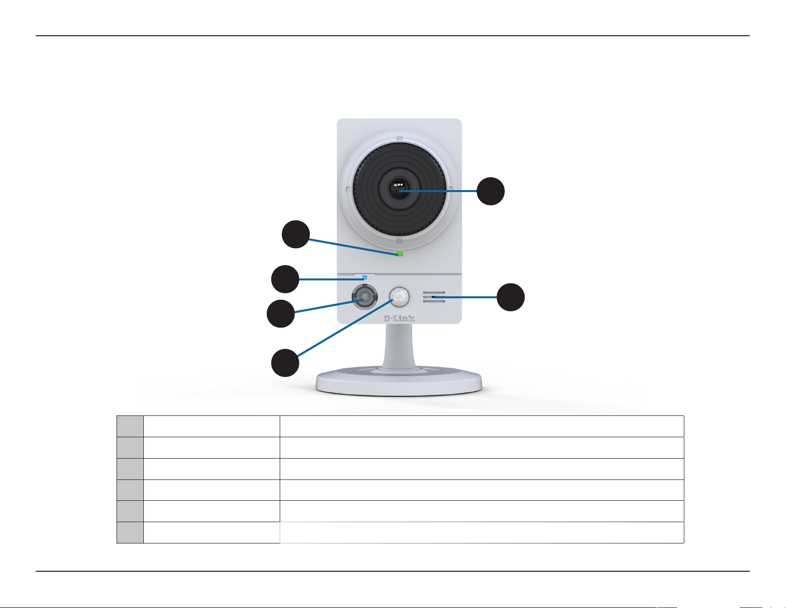
Front
5
1
2
6
3
4
1 Power/Status LED
2 WPS Status LED Indicates the WPS connection status of the camera.
3 White Light LED
4 PIR Sensor
5 Camera Lens Allows you to record or view video of the surrounding area.
6 Microphone Allows you to record or listen to audio from the surrounding area.
Indicates the camera's current status.
Used to illuminate the camera's eld of view at night.
Passive Infrared sensor for motion detection.
8D-Link DCS-2136L User Manual
Page 9
Section 1: Product Overview
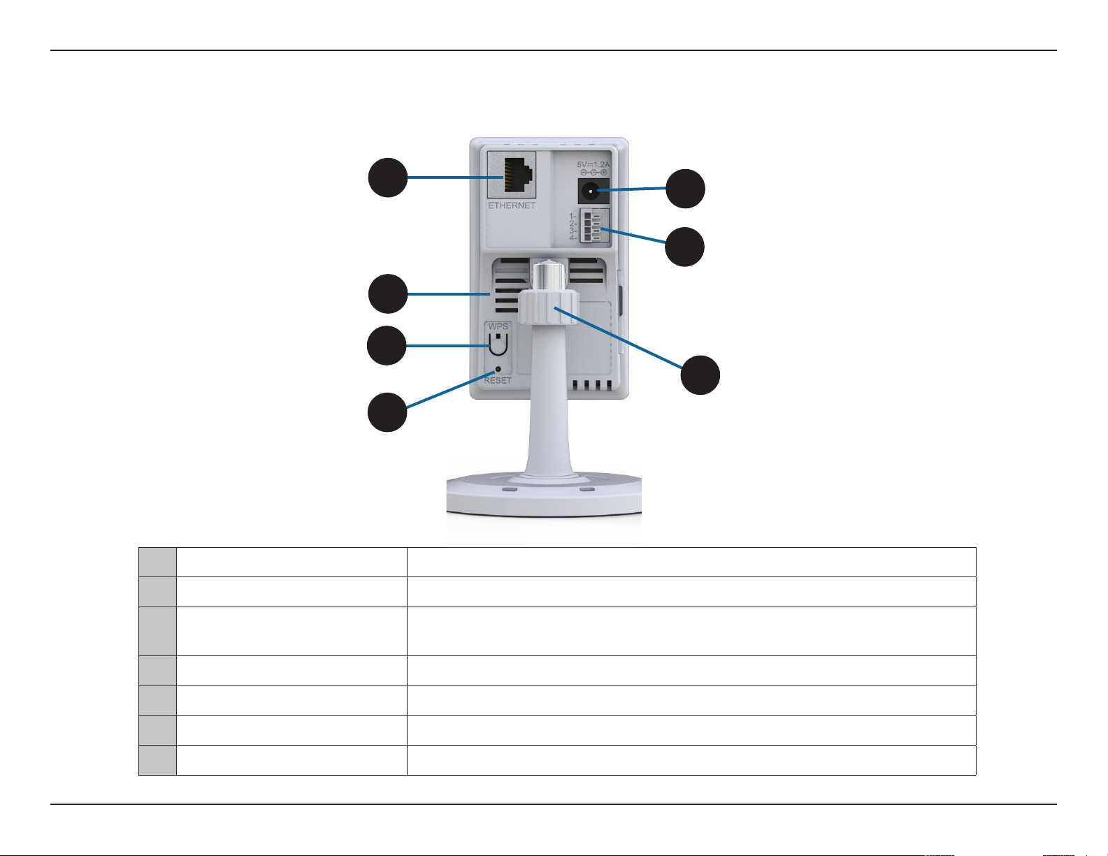
Rear
1 Ethernet Port
1
5
6
2
3
7
4
Using an Ethernet cable, connect the camera to your network.
2 Speaker Enables audio output.
3 WPS Button
4 Reset Button
5 Power Jack
6 DI/DO Connector
7 Adjustment Ring Tighten or loosen the adjustment ring to adjust the camera's position.
Press this button, then press the WPS button for ve seconds on your router to set
up a wireless connection automatically.
Press and hold this button for 10 seconds to reset the camera.
Connector for the supplied DC 5 V power adapter.
I/O connectors for external devices.
9D-Link DCS-2136L User Manual
Page 10
Section 1: Product Overview
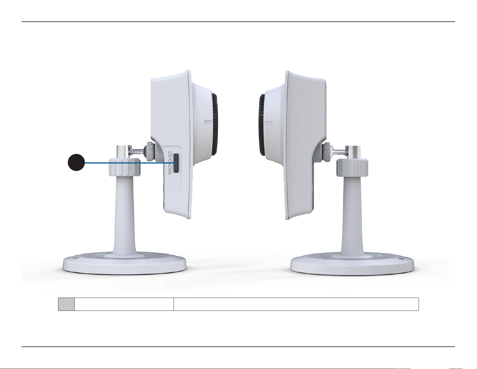
1
Sides
1 Micro SD Card Slot
Insert a MicroSD card for local storage of recorded video and images.
10D-Link DCS-2136L User Manual
Page 11

Section 2: Installation
Installation
Wireless Installation Considerations
This D-Link camera can connect to your wireless network from anywhere within the operating range of your wireless network. However, the
number, thickness, and location of walls, ceilings, or other objects that the wireless signals must pass through may limit the range. Typical ranges
vary depending on the types of materials and background RF (radio frequency) noise in your home or business. The key to maximizing wireless
range is to follow these basic guidelines:
1. Minimize the number of walls and ceilings between your camera and other network devices - each wall or ceiling can reduce your camera’s
range from 3-90 feet (1-30 meters).
2. Be aware of the direct line between network devices. A wall that is 1.5 feet thick (.5 meters), at a 45-degree angle appears to be almost 3 feet
(1 meter) thick. At a 2-degree angle, it looks over 42 feet (14 meters) thick. Position your devices so that the signal will travel straight through
a wall or ceiling (instead of at an angle) for better reception.
3. Building Materials make a dierence. A solid metal door or aluminum studs may weaken the wireless signal. Try to position your access points,
wireless routers, and other networking devices where the signal passes through drywall or open doorways. Materials and objects such as
glass, steel, metal, walls with insulation, water (sh tanks), mirrors, le cabinets, brick, and concrete will degrade your wireless signal.
4. Keep your camera at least 3-6 feet or 1-2 meters away from electrical devices or appliances that generate RF noise.
5. If you are using 2.4GHz cordless phones or other radio frequency sources (such as microwave ovens), your wireless connection may degrade
dramatically or drop completely. Make sure your 2.4GHz phone base is as far away from your wireless devices as possible. The base transmits
a signal even if the phone in not in use.
11D-Link DCS-2136L User Manual
Page 12

Section 2: Installation
Software Installation
There are three ways to set up your camera:
Zero Conguration Setup: If you have a D-Link Cloud Router, this is the easiest way to set up your camera. Refer
to "Zero Conguration Setup" on page 13.
Camera Setup Wizard: If you do not have a D-Link Cloud Router, use the DCS-2136L Setup Wizard to guide you
through setup and initial conguration of your camera. Refer to"Camera Setup Wizard" on page 16.
Manual Hardware Installation: This section shows you how to manually set up your camera. However, in order to
use the mydlink features of your camera, you will still need to run the DCS-2136L Setup Wizard. Refer to "Manual
Hardware Installation" on page 18.
12D-Link DCS-2136L User Manual
Page 13
Section 2: Installation
Zero Conguration Setup
If you have a D-Link Cloud Router, you can take advantage of Zero Conguration. Zero Conguration automatically congures
your camera for you, and adds it to your mydlink account. This allows you to set up your camera by simply plugging it in and
connecting it to your router. Then you will be able to remotely access your camera from the mydlink.com website.
If you do not have a D-Link Cloud Router, use the DCS-2136L Setup Wizard to guide you through setup and initial conguration
of your camera. Refer to"Camera Setup Wizard" on page 16.
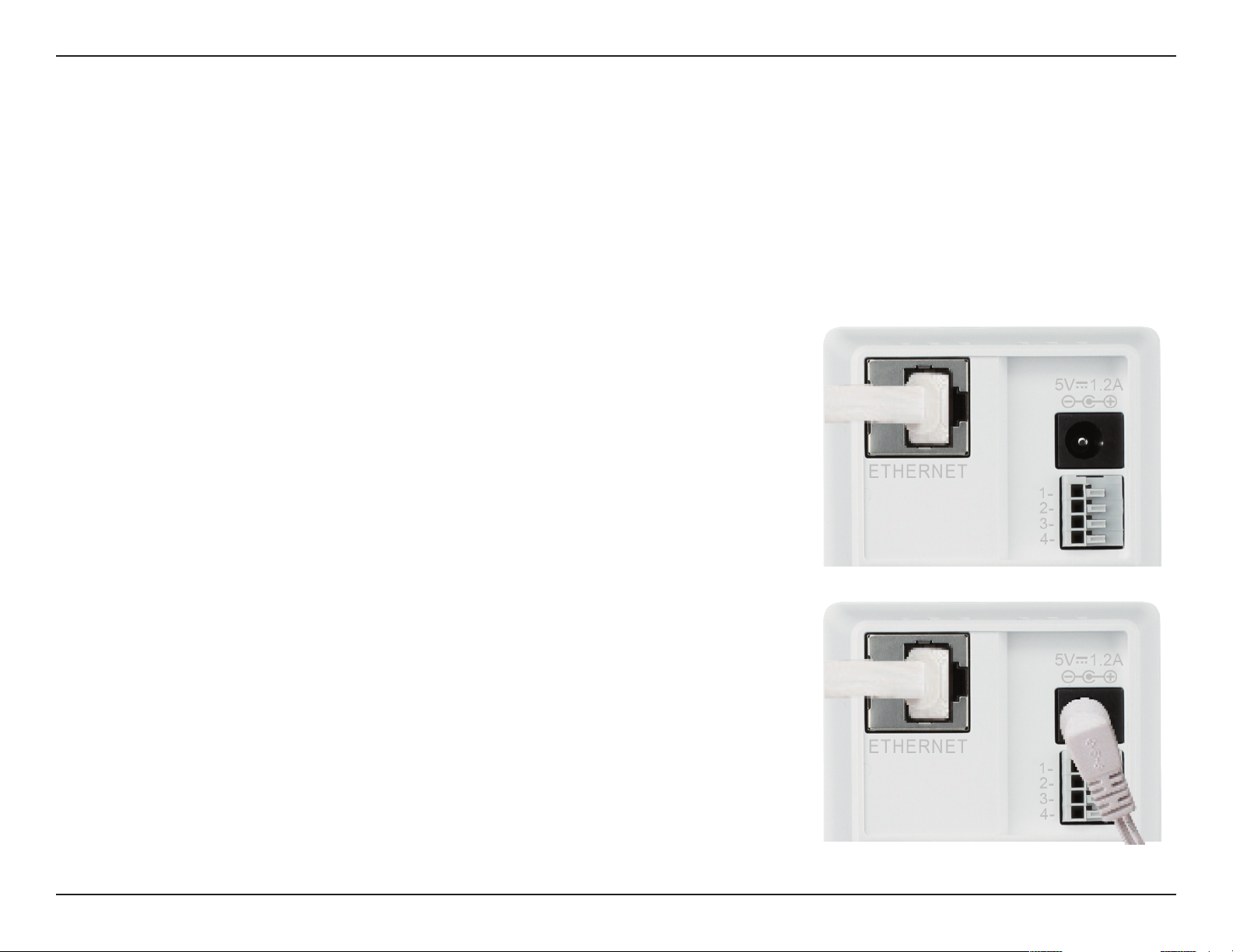
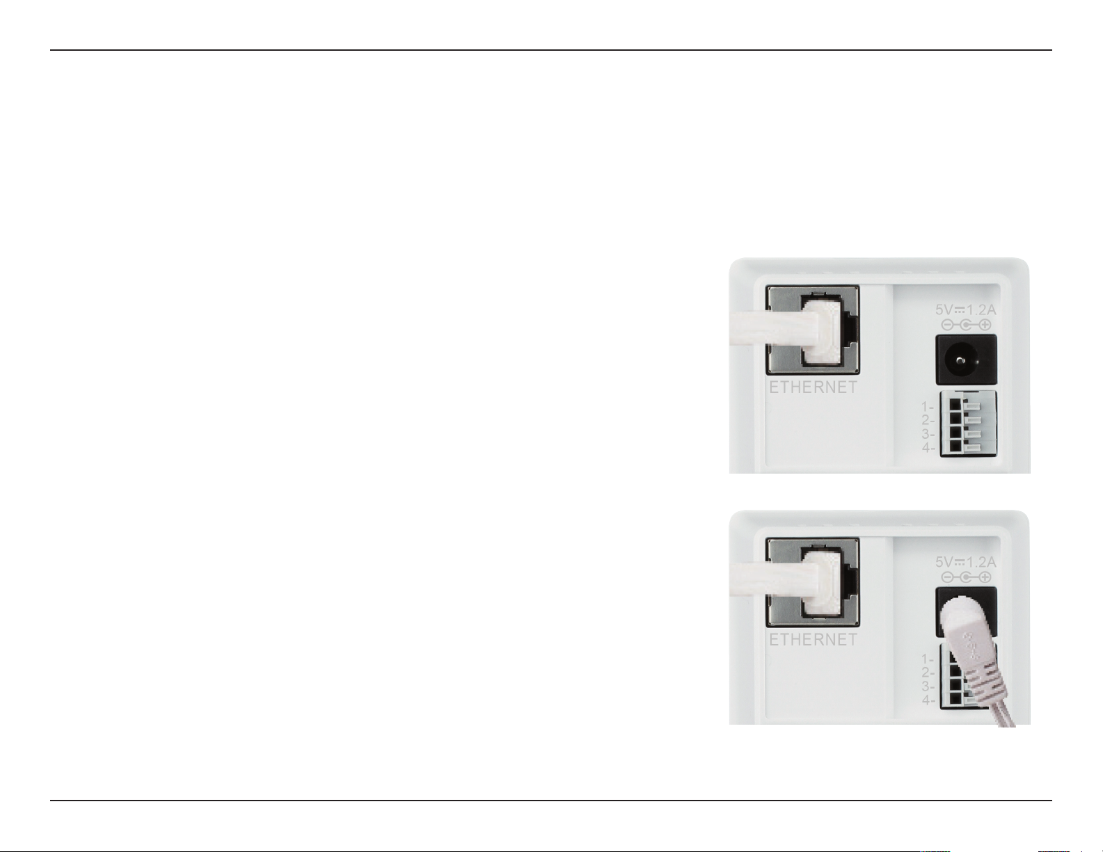
Connect Using an Ethernet Cable
If using an Ethernet connection: Connect the included Ethernet cable to the
Ethernet port located on the back of the DCS-2136L and connect it to your router.
Note: Using the Ethernet connection will also congure your wireless settings. If you
want to use your camera wirelessly, you can unplug the Ethernet cable once the setup
is complete.
Attach the External Power Supply
Attach the external power supply to the power receptor located on the rear panel
of the DCS-2136L. Connect the power supply to your wall outlet or power strip.
13D-Link DCS-2136L User Manual
Page 14
Section 2: Installation
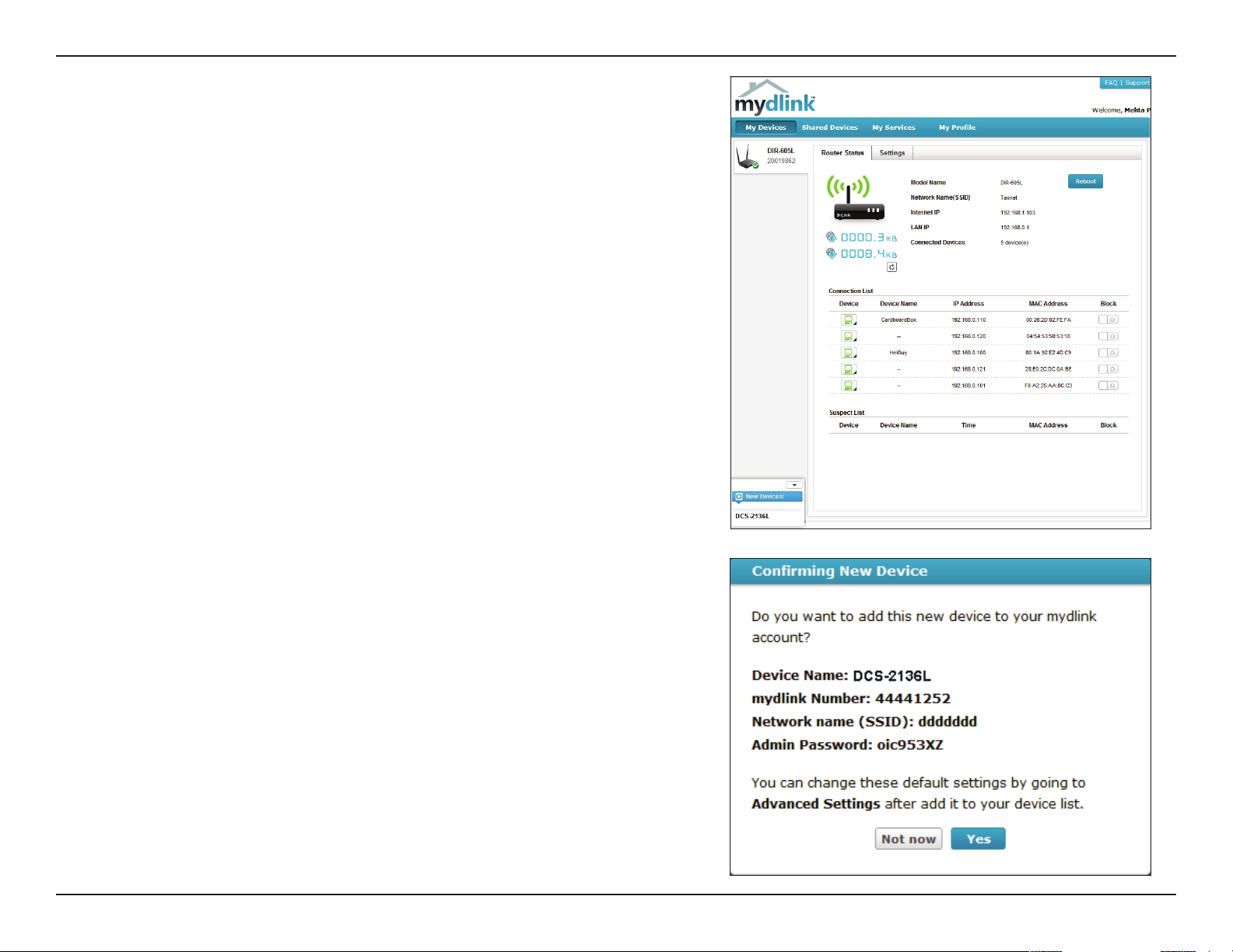
Conrm Your Camera's Addition to Your mydlink Account
From any computer, you can open a web browser and navigate to
http://www.mydlink.com. Log into your mydlink account. When
your camera is detected you will see, a New Devices! window in the
bottom-left corner of the screen. Click on DCS-2136L to continue.
A Conrming New Device window will open, containing a summary
of your settings. You will see the question, Do you want to add this
new device to your mydlink account?
Make a note of the settings and click Yes to conrm the addition of
the DCS-2136 to your mydlink account.
14D-Link DCS-2136L User Manual
Page 15
Section 2: Installation
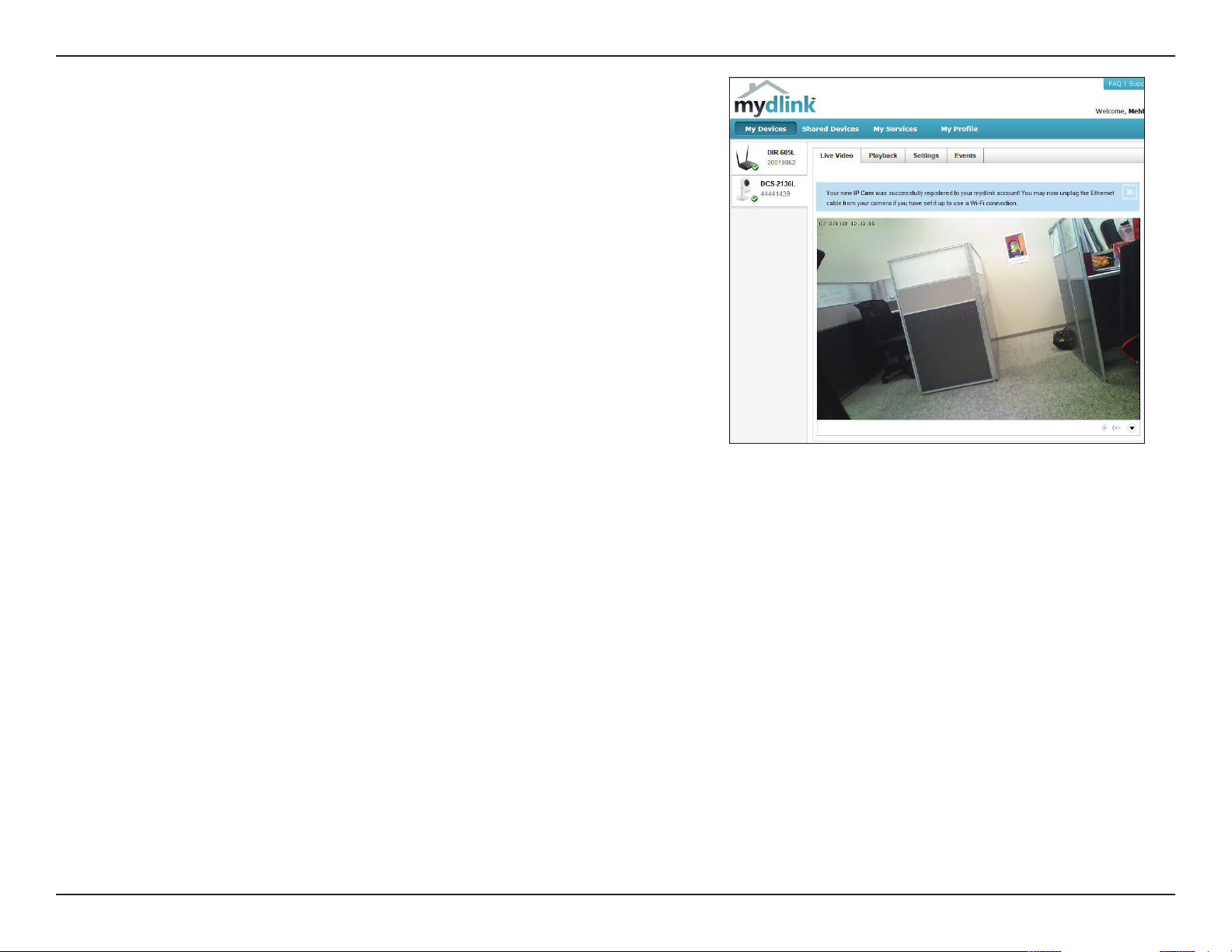
Under the mydlink Live View tab, you will see a message that says,
Your new IP cam was successfully registered to your mydlink account!
Under the message you will see live video.
If you wish to connect your camera to your router wirelessly, you
can now disconnect the Ethernet cable and move the camera to
its intended location. Your router's wireless settings have been
automatically transferred to the camera, and no further conguration
is required.
Skip to "Conguration" on page 22 for advanced conguration of your
camera.
15D-Link DCS-2136L User Manual
Page 16
Section 2: Installation
Camera Setup Wizard
If you do not have a D-Link Cloud Router, you can use a Windows or Mac computer to launch the DCS-2136L Setup Wizard,
which will guide you through the complete installation process. Download the Setup Wizard from http://www.mydlink.com/
download. Click your camera model and then under Wizard, click the link to the version (Windows or Mac) you want to download.
Depending on your web browser, you may need to right-click the link and select Save link as. (Mac Users can skip to the next page.)
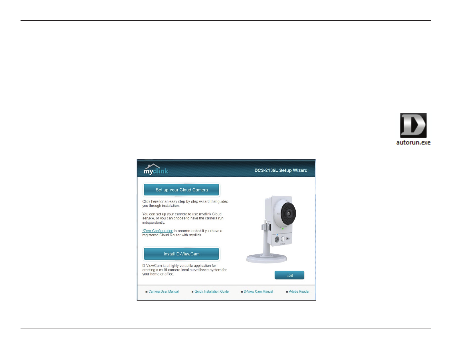
Windows Users
Extract ("unzip") the les to a folder on your computer and double-click the autorun.exe le. Click Set up your Cloud
Camera, and the DCS-2136L Setup Wizard will guide you step-by-step through the complete installation process.
Follow the on-screen instructions to connect your hardware, congure your camera, and register your DCS-2136L
with your mydlink account.
Note: At the end of the camera setup process, you will see a summary that includes the camera's IP address. Make a note of it. You will need the IP address
for advanced conguration of your camera. Refer to "Conguration Interface" on page 22.
16D-Link DCS-2136L User Manual
Page 17
Section 2: Installation
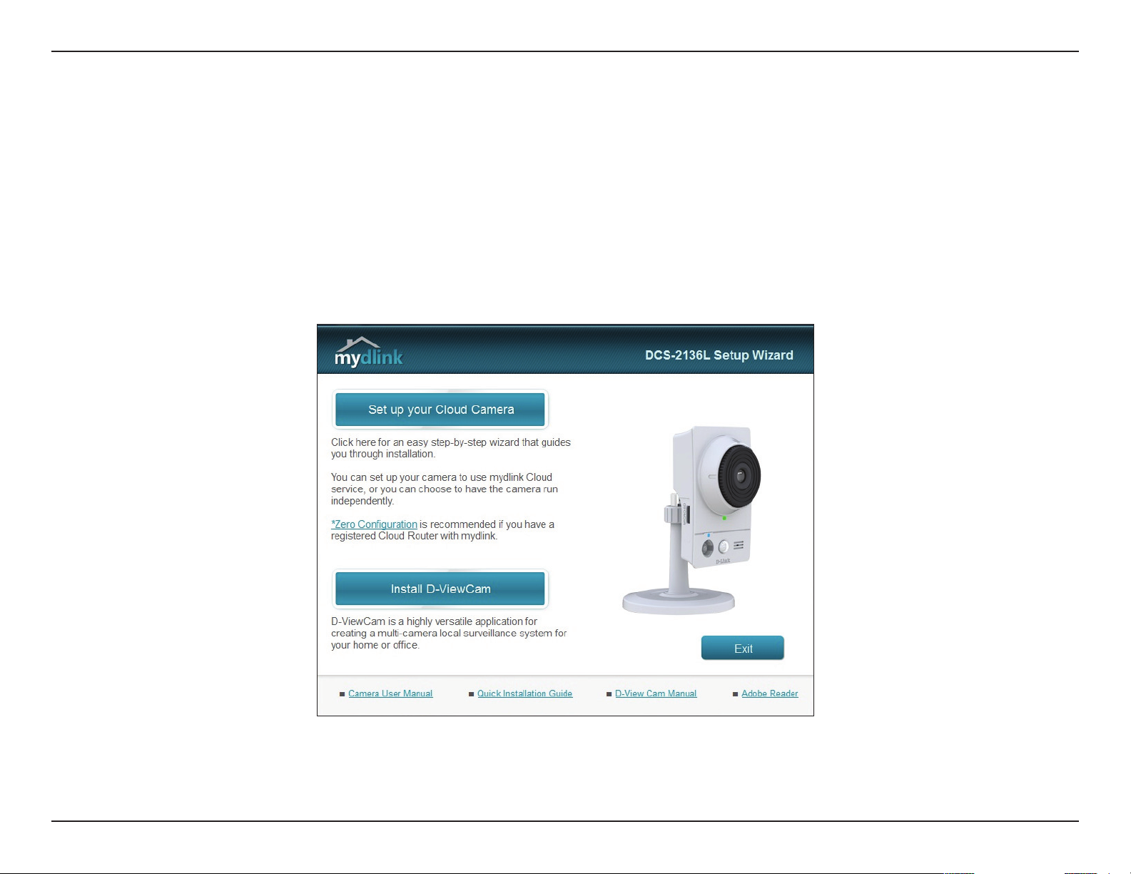
Mac Users
Instructions on the previous page describe the Setup Wizard download from http://www.mydlink.com/download. Open the
SetupWizard le and launch the application.
After about 20-30 seconds, the DCS-2136L Setup Wizard will open, which will guide you step-by-step through the complete
installation process. Follow the on-screen instructions to connect your hardware, congure your camera, and register your
DCS-2136L with your mydlink account.
Note: At the end of the camera setup process, you will see a summary that includes the camera's IP address. Make a note of it. You will need the IP address
for advanced conguration of your camera. Refer to "Conguration Interface" on page 22.
17D-Link DCS-2136L User Manual
Page 18
Section 2: Installation
Manual Hardware Installation
If you prefer to set up your camera manually, without using the Camera Setup Wizard, follow these steps*. If your router supports
WPS (Wi-Fi Protected Setup), you can simply attach the power supply and go to "WPS - Push Button Setup" on page 19.
*Note: In order to use the mydlink features of this product, you must use the DCS-2136L Setup Wizard. Refer back to "Camera Setup
Wizard" on page 16.
Connect Using an Ethernet Cable
Connect the included Ethernet cable to the Ethernet port located on the back of
the DCS-2136L and attach it to your network.
Attach the External Power Supply
Attach the external power supply to the DC power receptor located on the rear
panel of the DCS-2136L and connect it to your wall outlet or power strip.
Congure Your Camera
Refer to "Conguration" on page 22 for instructions on how to congure your
camera.
Note: If your router supports WPS (Wi-Fi Protected Setup), you have the option to
create a secure wireless connection with the push of a button. Refer to the next page
for details.
18D-Link DCS-2136L User Manual
Page 19
Section 2: Installation
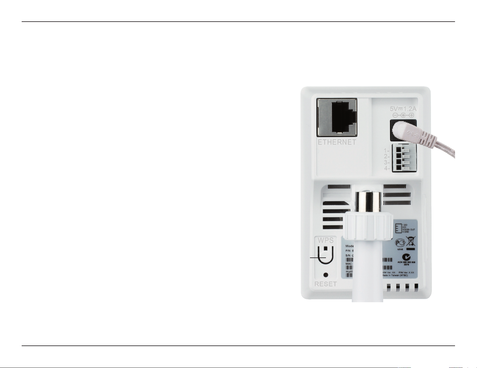
WPS - Push Button Setup
If your router supports WPS (Wi-Fi Protected Setup), utilize the WPS button on the camera to create a secure wireless connection
to your network.
To create a WPS connection:
Step 1
Press and hold the WPS button for approximately ve to six seconds.
The blue WPS status LED above the button will blink.
Step 2
Within 60 seconds press the WPS button on your router. On some
routers, you may need to log in to the web interface and click on
an on-screen button to activate the WPS feature. If you are not sure
where the WPS button is on your router, refer to your router’s User
Manual.
The DCS-2136L will automatically create a wireless connection to
your router. While connecting, the status LED will ash. When the
connection process is complete, the status LED will turn solid.
WPS Button
19D-Link DCS-2136L User Manual
Page 20
Section 2: Installation
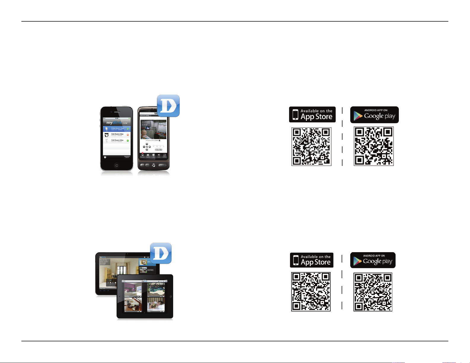
Download mydlink Lite/mydlink + Apps
mydlink Lite App (Free)
Search for “mydlink lite” to download and install the app on your smartphone or tablet when connected to the Internet. You
can also nd the app by scanning the QR code below with a QR code scan app.
System Requirements: iOS version 4.3 or above. Android version 2.1 or above.
mydlink+ App (Paid - Tablet Only)
Search for the word “mydlink+” to download and install the app on your tablet when connected to the Internet. You can also
nd the app by scanning the QR code below with a QR code scan app.
System Requirements: iOS version 4.3 or above. Android version 2.1 or above.
20D-Link DCS-2136L User Manual
Page 21
Section 2: Installation
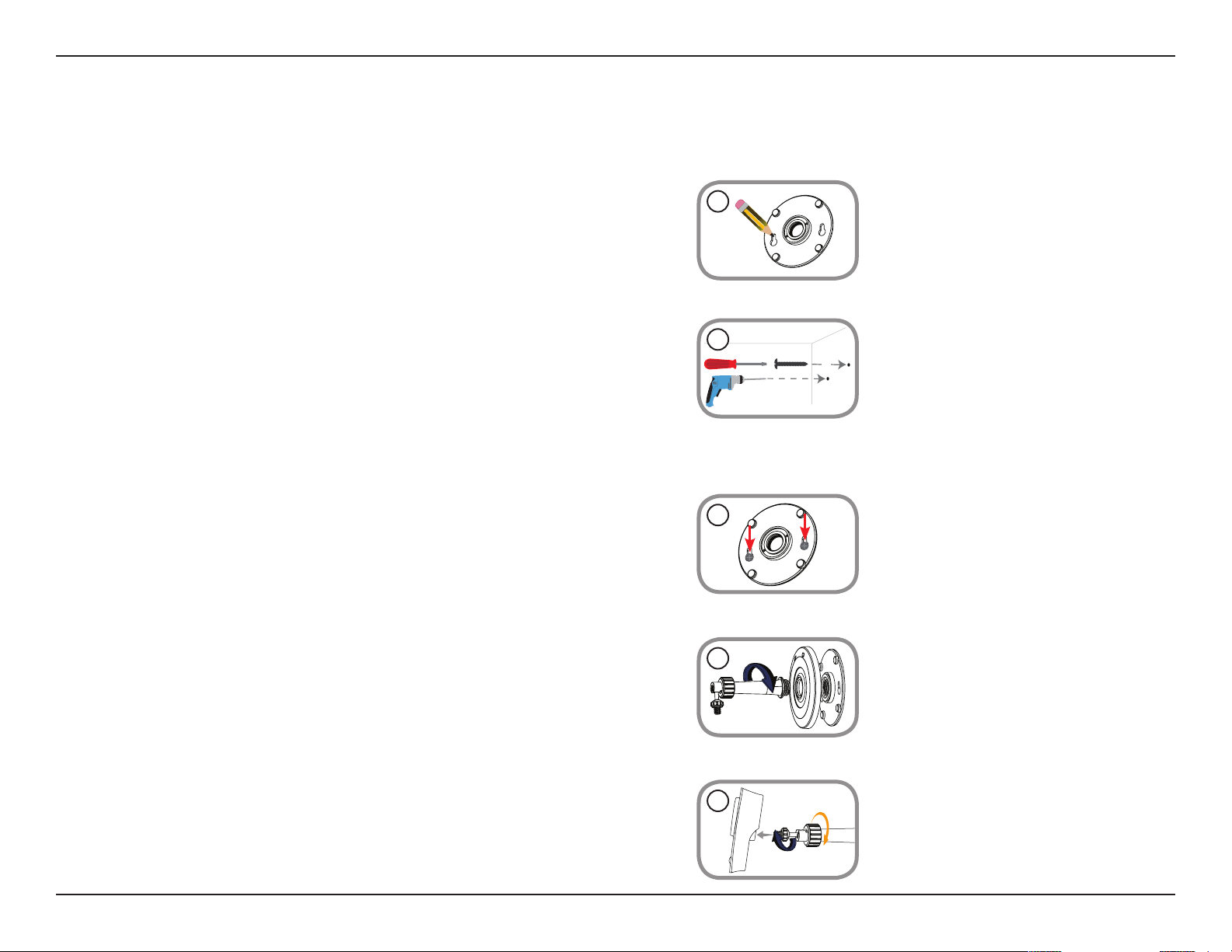
Mount the Camera
Refer to the steps below to assist you with mounting the camera. We suggest that you congure the camera before mounting it.
1.
Place the mounting base where you want to position the camera and
use a pencil to mark the holes.
1
2. Depending on the material of the wall or ceiling, use proper tools to
drill two holes or screws where you marked. If the wall is made out of
concrete, drill the holes first, insert the plastic anchors and then the
screws.
Note: The space between the camera and the screwheads should be 3mm.
3. Place the mounting base over the screw that is mounted on the
wall. Make sure to t the screw-heads over the big holes and slide it
downward to lock rmly. Lightly pull the base forward to make sure
that it is locked.
4. Place the base cover on the base and screw the camera stem clockwise
into the mounting base.
2
3
4
5. Adjust the angle of the camera as desired, then tighten the collar on
the camera stem to lock it in place.
5
21D-Link DCS-2136L User Manual
Page 22
Section 4: Conguration
Conguration
Conguration Interface
The camera's built-in conguration interface allows you to access to your DCS-2136L through the Internet. In order to access
the interface, you need the IP address of your DCS-2136L. The simplest way to acquire the camera's IP address is by using the
Camera Setup Wizard. At the end of the setup process there is a summary screen that includes the camera's IP address. If you
did not launch the wizard but would like to, refer back to "Camera Setup Wizard" on page 16.
Note: If you choose not to use the Camera Setup Wizard, you can get the camera's IP address from your router.
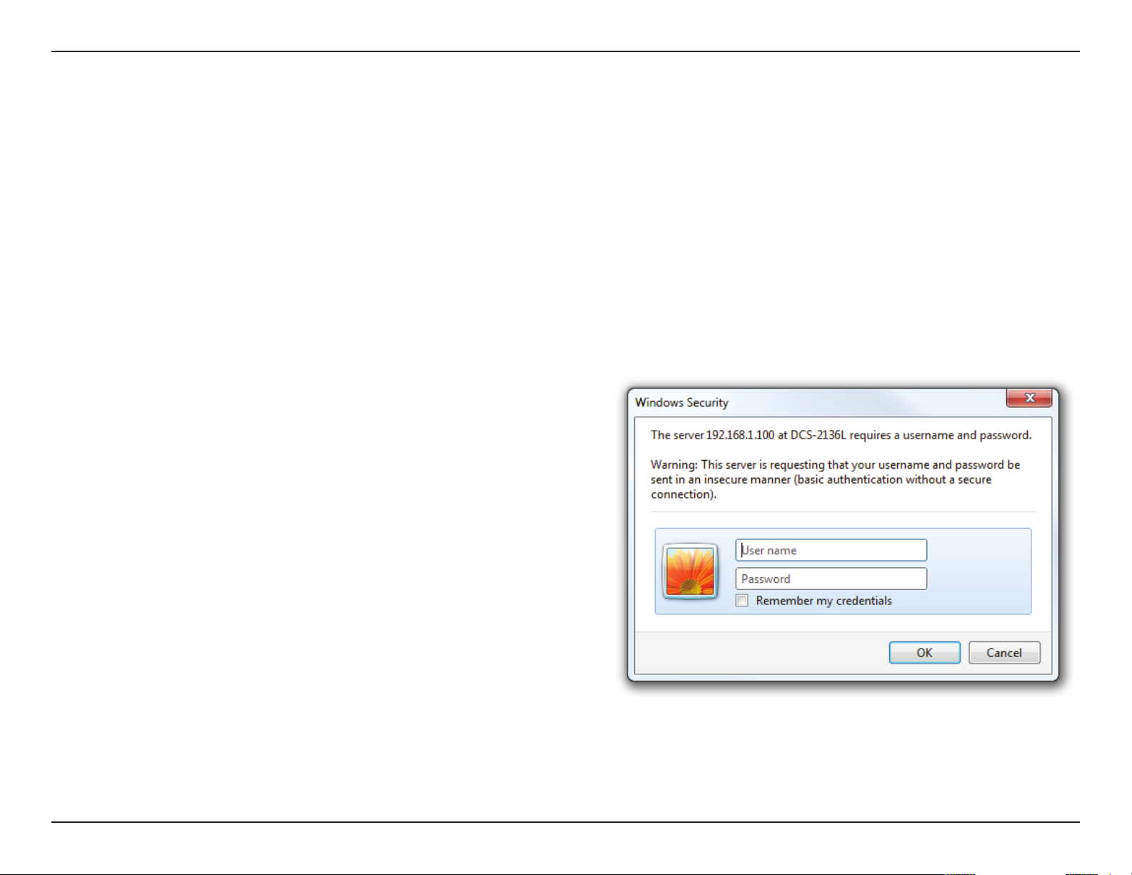
Open a web browser (e.g., Internet Explorer, Chrome, Firefox, or
Safari). Enter the IP address of your camera. You will see a login
window. For the User name enter admin. Enter the password
you created in the Setup Wizard. If you did not create a password,
by default the password is blank. Click OK.
22D-Link DCS-2136L User Manual
Page 23
Section 4: Conguration
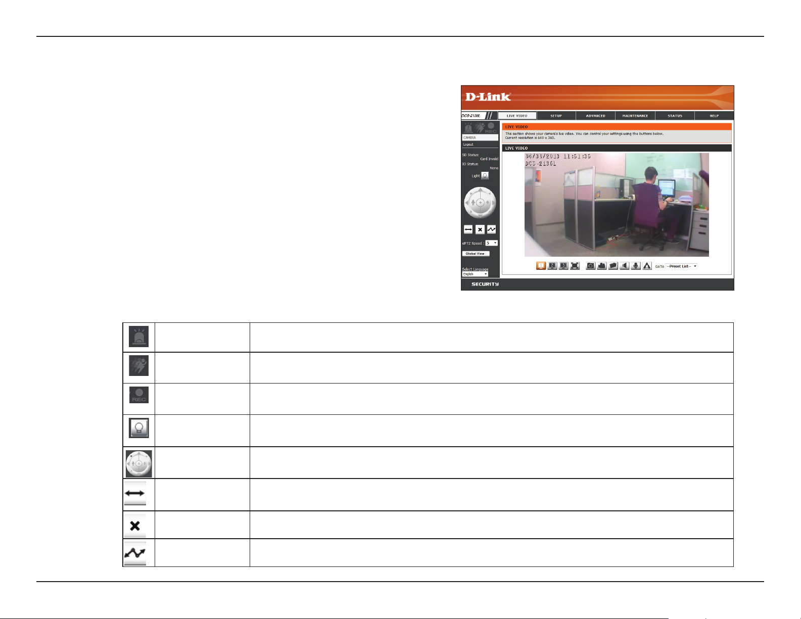
Live Video
View your camera’s live video from this screen. You can select any of the
icons listed below to operate the camera.
Use your mouse to zoom in and out on the live video image. Right-click
to zoom out or left-click to zoom in on the image.
SD Status:
IO Status:
This option displays the status of the SD card. If no SD
card has been inserted, this eld will say, Card Invalid.
This option displays the status of your I/O device if a
device is connected. If not connected, this eld will
say, None.
Digital Input
Indicator
Motion Trigger
Indicator
Recording
Indicator
White Light LED This button may be used to enable or disable the white light LED. The functionality depends on
Control Pad
Auto Pan This button starts the automatic panning function. The camera will pan back and forth within
This indicator will change to amber when a digital input signal is detected.
This indicator will change to amber when a trigger event occurs.
Note: The video motion feature for your camera must rst be enabled.
This indicator will change to amber when a recording is in progress.
the settings you select. Refer to "White Light LED" on page 54.
This control pad can be used to electronically pan, tilt, and zoom (ePTZ) within the camera's
predened view area, if one has been dened.
the Field of View (FOV).
Stop This button stops automatic panning function.
Preset Path If a preset path has been dened, this button will start the camera's motion along the path. See
Go To Preset List on the next page.
23D-Link DCS-2136L User Manual
Page 24

Section 4: Conguration
ePTZ Speed:
Global View:
Language:
Go To:
Preset List
Click on the arrow to select a value between
0 and 64. (Zero is the slowest and 64 is the
fastest speed for pan, tilt, and zoom.)
This window indicates the total eld of view
(FOV) of the camera.
You have the option to select a dierent
language for the interface using this menu.
If any presets have been dened, you will be
able to click on the arrow and select a preset
from the list.
Video Prole 1
Video Prole 2
Record a Video Clip
Set a Storage Folder
Video Prole 3
Full screen mode
Taking a Snapshot
Start/Stop Audio In (from microphone)
Start/Stop Audio Out (to speaker)
Start/Stop Digital Output
24D-Link DCS-2136L User Manual
Page 25

Section 4: Conguration
Setup
Setup Wizards
This screen provides setup wizards to guide you through connecting your camera to the network and setting up your motion detection preferences.
If you have experience with camera conguration, you can skip the wizards and adjust the settings manually.
Internet
Connection
Setup Wizard:
Manual
Internet
Connection
Setup:
Motion
Detection Setup
Wizard:
Manual
Motion
Detection
Setup:
You can use the Internet Connection Setup Wizard to
connect your camera to your network or directly to
the Internet. Refer to step-by-step instructions for the
"Internet Connection Setup Wizard" on page 26.
To manually setup your camera's connection to your
network or to modify the settings, refer to "Network
Setup" on page 31.
You may congure motion detection using the
Motion Detection Setup Wizard. Refer to step-by-step
instructions for the "Motion Detection Setup Wizard"
on page 29.
If you would prefer to setup the camera’s motion
detection manually, refer to "Enable Motion Detection"
on page 42.
25D-Link DCS-2136L User Manual
Page 26

Section 4: Conguration
Internet Connection Setup Wizard
The Internet Connection Setup Wizard will guide you through a step-by-step
process to congure your DCS-2136L and connect your IP camera to the
network. Click Next to continue.
Note: this wizard will not register your camera with mydlink.com.
Select DHCP (Dynamic Host Conguration Protocol) if you want your DHCP
server (usually enabled on your router) to assign the camera its IP settings.
If you want to manually assign the IP settings, select Static IP Client and
enter the following details from your ISP:
IP Address:
Subnet Mask:
Default Router:
Primary DNS:
Secondary DNS:
If you are required to connect using PPPoE (Point to Point Protocol over
Ethernet), select Enable PPPoE and enter the User Name and Password
for your PPPoE connection. Only select this option if your camera is directly
connected to your broadband modem. If it is on a network with a router
or gateway, do not select this option.
Click Next to continue.
Enter an IP Address for your camera.
Enter the Subnet Mask of your network.
Enter the Default Gateway address. This is usually the
IP address (LAN) of your router.
Enter the primary DNS server’s IP address. This is usually
also the IP address (LAN) of your router.
Enter the secondary DNS server’s IP address. This eld
is optional.
26D-Link DCS-2136L User Manual
Page 27

Section 4: Conguration
If you have a Dynamic DNS (Dynamic Domain Name System) account, you
may have an IP address that changes frequently. Enabling DDNS allows your
camera to update your IP address automatically, maintaining accessibility.
Enable DDNS:
Server Address:
Host Name:
User Name:
Password:
Timeout:
Click to enable the DDNS updating function.
Select your DDNS server from the drop down menu.
Enter the Host Name of the DDNS server.
Enter your User Name or the e-mail address used to
connect to the DDN server.
Enter the Password used to connect to the DDNS
server.
You can specify how often the camera noties the
DDNS server of its current global IP address by entering
a whole number representing hours.
Click Next to continue.
27D-Link DCS-2136L User Manual
Page 28

Section 4: Conguration
Create a unique name for your camera. Assign it to your DCS-2136L by
entering it into the IP Camera Name eld. Click Next to continue.
Select the Time Zone that corresponds to your camera's location in order to
ensure that scheduled events occur at the correct time. If the selected Time
Zone observes daylight saving time, check the Enable Daylight Saving
box. You may select Auto Daylight Saving to have DST set automatically,
or select Set Date and Time Manually so that you can set the start and
end time of DST yourself.
Click Next to continue.
A summary of your camera settings is displayed for conrmation. If the
settings are incorrect, click Back to make changes. Otherwise click Apply.
Note: Make a note of the IP camera settings so you can access your DCS-2136L
on your network or by using a web browser.
28D-Link DCS-2136L User Manual
Page 29

Section 4: Conguration
Motion Detection Setup Wizard
The Motion Detection Setup Wizard will guide you through a step-by-step
process to congure your camera's motion detection. Click Next to continue.
Step 1
Check the box by Enable Video Motion to enable motion detection.
Click on either Snapshot or Video Clip to specify what the camera should
capture when motion is detected.
Refer to "Enable Motion Detection" on page 42 for details about how to set
sensitivity, how much movement is required before triggering a camera
event, etc. Click Next to continue.
Step 2
This step allows you to specify a motion detection schedule. Check the
box by Always to record whenever motion is detected. Or you can check
the boxes by the days and use the drop-down menu to select the hours
when you would like your camera to detect motion. Click Next to continue.
29D-Link DCS-2136L User Manual
Page 30

Section 4: Conguration
Step 3
This step allows you to specify your preferences regarding notication of
camera events. Click on Do not notify me if you choose not to receive
event notication. Otherwise, select Email or FTP. Enter the relevant
information for your e-mail or FTP account. Click Next to continue.
Step 4
You have completed your IP Camera Setup. A summary of your selections
is displayed for conrmation. If settings are incorrect, click Back to make
changes. Otherwise click Apply.
Wait a few moments while your camera saves the settings and restarts.
If you already connected your IP camera to the network using the Setup
Wizard, skip to the section entitled "Wireless Setup" on page 34.
30D-Link DCS-2136L User Manual
Page 31

Section 4: Conguration
Network Setup
Use this screen to congure the network connections for your camera, or to
modify your network settings. After making changes, click Save Settings.
DHCP:
Static IP Client:
IP Address:
Subnet Mask:
Default router:
Primary DNS:
Secondary DNS:
Select this option if you have a DHCP server (i.e. router)
running on your LAN (local area network), and would
like your camera to obtain an IP address automatically.
Select this option for a static or xed IP address. You
can obtain a static or xed IP address for your camera
from your network administrator.
Enter the xed IP Address for your camera in this eld.
Enter the Subnet Mask for your network. This number
is used to determine if the destination is in the same
subnet as host devices.
Enter the default gateway address for the router that
will be used to forward the data outside of the network.
Enter the IP address of the Primary DNS (Domain
Name Server) that translates names into IP addresses.
Enter the IP address of the Secondary DNS (optional).
The secondary DNS acts as a backup to the primary.
Enable UPnP
Presentation:
Enable UPnP
Port Forwarding:
Check the box to Enable UPnP (Universal Plug and
Play). This setting allows your camera to be congured
as a UPnP device on your network.
Check to Enable UPnP Port Forwarding. This setting
allows the camera to add port forwarding entries into
the router automatically on a UPnP capable network.
31D-Link DCS-2136L User Manual
Page 32

Section 4: Conguration
Enable PPPoE:
User Name &
Password:
HTTP Port:
Access Name for
Streams 1 thru 3:
HTTPS Port:
Check this box to Enable PPPoE (Point to Point Protocol
over Ethernet). Only select this option if your camera is
directly connected to your broadband modem. If it is
on a network with a router or gateway, do not select
this option.
Enter the User Name and Password for your PPPoE
account. You may obtain this information from your
Internet Service Provider (ISP).
The default number is 80 for the port allocated to
connect the camera to the Internet using a standard
web browser.
The default name is video#.mjpg, where # corresponds
with the number of the stream.
The default number is 443 for the port allocated to
connect the camera to the Internet using a secure web
browser.
Authentication:
RTSP Port:
Enable CoS:
Click the arrow for the drop-down menu in order to
Enable/Disable Authentication of RTSP (Real Time
Streaming Protocol).
The default port number is 554 for the port allocated
to connect to an IP camera using a streaming mobile
device, like a mobile phone or PDA. You may specify
the address of a particular stream. Example: live1.sdp
can be accessed at rtsp://x.x.x.x/video1.sdp where the
x.x.x.x represents the IP address of your camera.
Check to Enable Cos (Class of Service). This setting
implements assignment of priority to packets being
transmitted, using a best-eort policy. This means
there is no guarantee of level of service in terms of
bandwidth and delivery time.
32D-Link DCS-2136L User Manual
Page 33

Section 4: Conguration
Enable QoS:
Enable IPV6:
Enable Multicast
for streams:
Check to Enable QoS (Quality of Service). This setting
allows you to specify a trac priority policy to ensure
consistent Quality of Service during busy time periods.
If the DCS-2136L is connected to a router that itself
implements QoS, the router's settings will override the
QoS settings of the camera.
Check EnableIPV6 to manually set up the IP address.
This setting only works if your network and hardware
support IPV6 protocol, which is the latest version of
Internet Protocol (IP).
Note: the vast majority of Internet trac in the U.S.
currently uses IPv4.
Check the boxes to multicast each of the available
streams using group addresses. If you do not want to
use the default settings, you can enter the port and
Time to Live (TTL) values you prefer.
Verify your settings and click Save Settings.
33D-Link DCS-2136L User Manual
Page 34

Section 4: Conguration
Wireless Setup
Use this screen to set up and congure the wireless settings on your
camera. After making changes, click the Save Settings.
Enable Wireless:
Site Survey:
SSID:
Wireless Mode:
Channel:
Authentication:
Check the box to Enable Wireless.
Click Rescan to scan for available wireless networks. Then
you can use the drop-down menu to select a wireless
network from the SSID List. The elds for related
information (Wireless Mode, Channel, Authentication,
Encryption) will be automatically completed.
You may enter an SSID (Service Set Identier) manually
if you did not use Site Survey to select an available
wireless network.
Use the drop-down menu to select the mode of the
wireless network you want to connect your camera to.
Infrastructure is for connecting to an access point or
router. Ad-Hoc is for connecting directly to a computer.
If you are using Ad Hoc mode, select the Channel of the
wireless network you wish to connect to, or select Auto.
Select the authentication type for your wireless
network - Open, Shared, WPA-PSK, or WPA2-PSK.
Encryption:
Key:
For WPA-PSK or WPA2-PSK authentication, you need
to specify whether your wireless network uses TKIP or
AES encryption. For Open or Shared authentication,
specify WEP encryption.
If you use WEP, WPA-PSK, or WPA2-PSK authentication,
enter the Key, or password, for your wireless network.
34D-Link DCS-2136L User Manual
Page 35

Section 4: Conguration
Dynamic DNS
If you have a Dynamic DNS (Dynamic Domain Name System) account, you
may have an IP address that changes frequently. Enabling DDNS allows you
to assign a website domain name to your IP camera. Then you can connect
by entering the domain name, regardless of your actual IP address.
Enable DDNS:
Server Address:
Host Name:
User Name:
Password:
Timeout:
Status:
Check this box to Enable DDNS.
Select the Dynamic DNS provider from the drop-down
menu or enter the server address manually.
Enter the Host Name of the DDNS server.
Enter the User Name or e-mail used to connect to
your DDNS account.
Enter the Password used to connect to your DDNS
server account.
Enter the DNS Timeout value in hours.
Indicates the connection status, which is automatically
determined by the system.
Click Save Settigs to save your changes.
35D-Link DCS-2136L User Manual
Page 36

Section 4: Conguration
Image Setup
From this screen, you can congure the image settings for your camera. A
preview of the image will be shown below the Live Video heading.
Enable Privacy
Mask Setting:
Mirror:
Flip:
Power Line:
White Balance:
Check the box to Enable Privacy Mask. You can
specify up to three rectangular areas for exclusion
from video recordings and snapshots. Click and drag
the mouse over the camera image to draw a privacy
mask. If you right click on the camera image you will
see the following menu options:
Disable All: Disables all mask areas
Enable All: Enables all mask areas
Reset All: Clears all mask areas.
Select On to mirror the image horizontally.
Select On to ip the image vertically. If you turn Flip
on, you may want to consider turning Mirror on as well.
Select the frequency (60 Hz or 50 Hz) that is used by
your power lines to avoid interference or icker.
Use the drop-down menu to adjust White Balance
settings for dierent environments. Select from Auto,
Outdoor, Indoor, Fluorescent, and Push Hold.
Exposure Mode:
Select an Exposure Mode. Use the drop-down menu to
select from Indoor, Outdoor, or Night environments.
Select Moving to capture moving objects. The Low
Noise option generates a high-quality picture with a
minimum amount of noise. You can also create three
dierent custom exposure modes.
36D-Link DCS-2136L User Manual
Page 37

Section 4: Conguration
Max Gain:
Denoise:
Brightness:
Contrast:
Saturation:
Sharpness:
WDR Level:
You can adjust the Max Gain setting in order to apply
the maximum amount of gain to brighten the picture.
Adjust this setting to control the amount of noise
reduction that will be applied to the picture.
Adjust this setting to compensate for backlit subjects.
Adjust this setting, which is dened by the dierence
between the darkest and lightest areas of an image.
For example, setting a higher contrast may improve
the image quality on a day when the sky is dark gray.
Adjust the intensity of color, ranging from grayscale to
fully saturated.
Adjust the degree of sharpening to be applied to the
image.
Adjust the WDR Level (Wide Dynamic Range). WDR
allows the camera to record greater scene details, from
darker shadows to brighter highlights. This is especially
important in environments like lobby entrances, parking
lots, and ATMs, where WDR adjustment can make a big
dierence in the viewer's ability to identify details.
3D lter:
Reset Default:
Adjust this setting to reduce image artifacts. The desired
result is less blur when the video is recorded during the
night or in areas where there are low levels of light. Select
from Low, Medium, or High.
Click to reset the camera to factory default settings.
37D-Link DCS-2136L User Manual
Page 38

Section 4: Conguration
Audio and Video
You may congure up to three dierent video proles on your camera from
the Audio and Video screen. You can set up proles for your computer that
are dierent than proles intended for your mobile devices. In addition,
you may congure the two-way audio settings for your camera.
Aspect ratio:
Mode:
Frame size/View
window area:
Click the drop-down menu to change the aspect ratio
of the video. Aspect ratio is the ratio between the width
and height of the image. Select either 4:3 standard or
16:9 widescreen.
Select a mode for the prole from the drop-down menu.
The video codec options are JPEG, MPEG-4, or H.264.
Frame size determines the total capture resolution,
and View window area determines the Live Video
viewing window size. When the Frame size is larger
than the Live Video size, you can use the ePTZ controls
to look around.
16:9 1280 x 720, 800 x 450, 640 x 360, 480 x 270, 320
x 176, 176 x 144
4:3 1024 x 768, 800 x 600, 640 x 480, 480 x 360, 320
x 240, 176 x 144
Note: If your View window area is the same as your
Frame size, you will not be able to use the ePTZ function.
38D-Link DCS-2136L User Manual
Page 39

Section 4: Conguration
Maximum frame
rate:
Video Quality:
Constant bit
rate:
Fixed quality:
Audio in o:
Audio in gain
level:
Click the arrow to select a Maximum Frame Rate.
Recording at a higher frame rate provides smoother
motion for videos, and requires more bandwidth.
Lower frame rates will result in stuttering motion, and
requires less bandwidth.
Select Constant bit rate or Fixed quality.
Select Constant bit rate if you want a xed bandwidth,
regardless of video quality. Higher bit rates result in
better video quality, requiring greater bandwidth.
Select an image quality level for the camera to
maintain. The intent of this option is to allow the user
to optimize bandwidth utilization.
Check this box to mute incoming audio.
Adjust this setting to control the amount of gain
applied to incoming audio and increase the volume.
Audio out o:
Audio out
volume level:
Check this box to mute outgoing audio.
Adjust this setting to control the amount of gain
applied to outgoing audio and increase the volume.
After making changes, click Save Settings.
39D-Link DCS-2136L User Manual
Page 40

Section 4: Conguration
Preset
This screen allows you to preset points for the ePTZ (Point, Tilt, Zoom)
function of the camera. You can look around within the camera's viewable
area by using the zoom function. Presets allow you to quickly go to and
view a specic area your camera is covering. Plus, you can create preset
sequences, which will automatically change the camera's view from one
preset to the next, according to a predened order and specic timing.
Note: Only when you set the View window area smaller than the Frame
size will you be able to use the ePTZ function. Refer to "Audio and Video" on
page 38.
Video Prole:
ePTZ Speed:
Arrow Buttons
and Home
Button:
Input Preset
Name:
Preset List:
Click on the arrow and select a number for the Video
Prole you would like to use.
Click on the arrow and select a value for the ePTZ
Speed. 0 is the slowest and 64 is the fastest.
Use the arrows to move to a specic part of the viewing
area, which you can then capture as a preset. Click the
Home button to return to the center of the viewing area.
Enter the name of the preset you captured, then click
the Add button to create a new preset. If you select an
existing preset from the Preset List, you can change
its name by typing in a new name, then clicking the
Rename button.
Click this drop-down menu to see a list of all the presets
that have been created. You can select one, then click
the GoTo button to change the displayed camera view
to the preset. Clicking the Remove button will delete
the currently selected preset.
40D-Link DCS-2136L User Manual
Page 41

Section 4: Conguration
Preset
Sequence:
Preset List:
This section allows you to create a Preset Sequence,
which will automatically change the camera's view
from one preset to the next, according to a predened
order and specic timing.
To add a preset to the sequence, select it from the
drop-down menu at the bottom of this window, set the
Dwell time to determine how long the camera view
will remain at that preset, then click the Add button.
The preset name will appear in the list, followed by the
dwell time for viewing that preset.
You can change your presets in the sequence by
selecting a preset, then clicking the arrow buttons to
move it higher or lower in the current sequence.
Clicking the trash can button will remove the currently
selected preset from the sequence.
If you want to change the dwell time for a preset, select
it from the list, enter a new dwell time, then click the
Update button.
41D-Link DCS-2136L User Manual
Page 42

Section 4: Conguration
Enable Motion Detection
Enabling Video Motion will allow your camera to use the motion
detection feature. You may draw a nite motion area that will be used for
monitoring.
Enable Video
Motion:
Sensitivity:
Percentage:
Draw Motion
Area:
Erase Motion
Area:
Check this box to enable the motion detection feature
of your camera.
Enter a Sensitivity value between 0 and 100. Species
the measurable dierence between two sequential
images that would indicate motion.
Enter a Percentage value between 0 and 100. Species
the amount of motion in the window being monitored
that is required to initiate an alert. If this is set to 50%,
the window must be halfway lled by a moving object
before motion detection is triggered.
To draw the motion detection area, drag your mouse
within the Live Video window (indicated by the red square).
To erase a motion detection area, simply click on the red
square that you want to remove.
Right clicking on the camera image brings up the
following menu options:
Select All: Draws a motion detection area over the
entire screen.
Clear All: Clears any motion detection areas that have
been drawn.
Restore: Restores a previously specied motion
detection area.
After making changes, click Save Settings.
42D-Link DCS-2136L User Manual
Page 43

Section 4: Conguration
Time and Date
This section allows you to automatically or manually congure, update,
and maintain the current time for your camera.
Time Zone:
Enable Daylight
Saving:
Auto Daylight
Saving:
Set Date and
Time Manually:
Oset:
Synchronize
with NTP Server:
NTP Server:
Select your Time Zone from the drop-down menu.
Check the box to Enable Daylight Saving Time.
Click to allow your camera to congure Daylight Saving
settings automatically.
Select this option to congure the Daylight Saving
manually. Then set Start time and End time using
drop-down menus for Month, Week, and Day of
week. Enter values for Hour and Minutes.
Select the amount of time to be added or removed
when Daylight Saving is enabled.
Enable this feature to obtain time automatically from
an NTP server.
Network Time Protocol (NTP) synchronizes the
DCS-2136L with an Internet time server. Choose the
one that is closest to your location.
Set the Date and
Time Manually:
Copy Your
Computer's
Time Settings:
Check this box to Set the Date and Time Manually.
Click to synchronize the time zone and Daylight Saving
information from your PC.
After making changes, click Save Settings.
43D-Link DCS-2136L User Manual
Page 44

Section 4: Conguration
ex.
Motion detection,
Periodically, Digital input,
System reboot
Event Condition
ex.
Snapshot, Video Clips
ex.
Email, FTP
Media
(what to send)
Server
(where to send)
Action
Event Setup
When an event is triggered, a specied action will be performed. As shown in the illustration below, an event can be triggered in various ways. For
example, when the camera detects motion, or when an external digital input device like a sensor detects a door opening.
After an event is triggered, either an e-mail notication can be delivered to a specied e-mail address, or images may be uploaded to an FTP server.
You can specify whether the DCS-2136L should send snapshots or videos to your e-mail address or FTP site.
Event Setup instructions begin on the next page.
44D-Link DCS-2136L User Manual
Page 45

Section 4: Conguration
To set up an Event, it is suggested that you start with Server and Media sections rst. Once the Server and Media are associated with an Event,
they can not be modied. In order to change the Server and Media, they must be removed from the Event.
The Event Setup screen includes four dierent sections:
• Server
• Media
• Event
• Recording
1. To add a new item - Server, Media, or Event, click Add. A screen will
appear and allow you to update the elds accordingly.
2. To remove the selected item from the drop-down menu, click Delete.
3. Click on the item from the drop-down menu to open a window for
modifying the item.
45D-Link DCS-2136L User Manual
Page 46

Section 4: Conguration
Add Server
You can congure up to ve servers to save snapshots and/or video to.
Server Name:
E-mail:
FTP:
Network
Storage:
SD Card:
Enter the unique name of your server.
Enter the conguration for the target E-mail server
account.
Enter the conguration for the target FTP server
account.
Specify a Network Storage location. Only one network
storage device is supported.
Use the camera's onboard SD card storage.
After making changes, click Save Settings.
46D-Link DCS-2136L User Manual
Page 47

Section 4: Conguration
Add Media
You can select from three types of media that can be sent when an Event
is triggered, Snapshot, Video Clip, and System Log.
Media Name:
Snapshot:
Source:
Send pre-event
image(s) [0~4]:
Send post-event
image(s) [0~7]:
File name prex:
Add date and
time sux to
le name:
Enter a unique name for Media Type you want to create.
Select this option to set the Media Type to snapshot.
Set the video prole to use as the media Source. Refer
to "Audio and Video" on page 38 for more information
about video proles.
Enter the number of pre-event images to take. The
pre-event images are images taken before the main
event snapshot. You can set up to four pre-event
images to be taken.
Enter the number of post-event images to take. The
post-event images are images taken after the main
event snapshot. You can set up to seven post-event
images to be taken.
Enter the prex name to be included in the le name.
Check the box to add date and time information as le
name sux.
47D-Link DCS-2136L User Manual
Page 48

Section 4: Conguration
Video clip:
Source:
Pre-event
recording:
Maximum
duration:
Maximum le
size:
File name prex:
System log:
Select this option to set the Media Type to Video Clip.
Select the video prole to use as the media Source.
Refer to "Audio and Video" on page 51 for more
information on video proles.
Enter the number of seconds to record before the
main event video clip starts. You can record up to four
seconds of pre-event video.
Enter the maximum number of seconds to record for
your video clips.
Set the maximum le size (in Kbytes) for your video
clips.
Enter the prex name that will be included in the
lename of saved video clips.
Select this option to set the Media Type to System Log.
This will save the event to the camera's System Log, but
will not record snapshots or video clips.
After making changes, click Save Settings.
48D-Link DCS-2136L User Manual
Page 49

Section 4: Conguration
Add Event
You can create and schedule a maximum of two events, each with its
own settings.
Event name:
Enable this
event:
Priority:
Delay:
Trigger:
Video Motion
Detection:
Periodic:
Enter a name for the Event.
Check this box to Enable this event.
Select the Priority for this event. The event with the
highest priority will be executed rst.
Enter the number of seconds for the Delay time before
checking for the next Event. This value is used for three
types of events - Video motion detection, Digital input,
and Passive infrared sensor.
Select an input type that triggers the Event. Choices
are described below.
When motion is detected during live video monitoring.
Select the windows that need to be monitored.
When an Event is triggered in specied intervals.
Specify the trigger frequency in minutes.
Digital input:
System Boot:
Network Lost:
Passive Infrared
Sensor:
When there is an external trigger input to the camera.
When the system boots up, an Event is triggered.
When the network connection is lost, an Event is
triggered.
Triggers an Event when the PIR sensor is activated by
moving infrared objects even in dark environment.
49D-Link DCS-2136L User Manual
Page 50

Section 4: Conguration
Event Schedule:
Time:
Trigger D/O:
Trigger white
light LED
Check the box by the days of the week for scheduling.
Click Always or click From and enter the time interval
as a range.
Check the box to trigger the digital output for a specic
number of seconds when an event occurs.
Check the box to trigger the white light LED. Select
Keep active during an event or specify the number
of seconds to keep active for during an Event.
After making changes, click Save Settings.
50D-Link DCS-2136L User Manual
Page 51

Section 4: Conguration
Here you can congure and schedule the recording settings.
Add Recording
Recording entry
name:
Enable this
recording:
Priority:
Source:
Recording
schedule:
Time:
Destination:
Total cycling
recording size:
Size of each le
for recording:
Enter a unique name for the Recording entry.
Check this box to Enable recording.
Select the Priority for this entry. The entry with the highest
priority value will be executed rst.
Select the Prole to be used a Source of the stream.
Check the box by the days of the week for recording.
Click Always or click From and enter the time interval as a
range.
Select None or select the folder where the video le will be
stored.
Enter storage size between 1MB and 2TB for video
recordings. New recordings will replace the oldest recording
when the total storage size exceeds this value.
If this option is selected, les will be separated based on the
le size you enter (in Mbytes).
Time of each le
for recording:
File Name Prex:
If this option is selected, les will be separated based on the
maximum length of time you specify (in seconds).
Enter the prex name to be included in the le name of the
video le(s).
After making changes, click Save Settings.
51D-Link DCS-2136L User Manual
Page 52

Section 4: Conguration
SD Card
Here you may view and manage the recorded les which are stored on
the SD card.
Files per page:
Refresh:
Delete:
View Recorded
Picture:
Playback
Recorded Video:
Format SD Card:
Select a number from the drop-down menu indicating
the number of les to view on this page at one time.
Click the link to reload the le and folder information
from the SD card.
Check the box by Delete, and then check the box by
the name of the le(s) you would like to remove and
click OK.
If the Picture les are stored on the SD card, you can
click on the link to the picture le you would like to
view.
If Video les are stored on the SD card, you can click on
the link to the video le you would like to view.
Click to automatically format the SD card and create
Picture and Video folders.
52D-Link DCS-2136L User Manual
Page 53

Section 4: Conguration
Advanced
Digital Input/Output
This screen allows you to control the behavior of digital input (DI) and
digital output (DO) devices. The I/O connector provides the physical
interface for DO and DI that is used for connecting a variety of external
alarm devices, such as IR-Sensors and alarm relays. The digital input is
used for connecting external alarm devices. Once the alarm is triggered,
images will be recorded and e-mailed.
Active State for
D/I or D/O:
The camera will send a signal when an event is triggered,
depending upon the type of device connected to the DI
circuit.
N.C. stands for Normal Closed. This means that the
normal state of the circuit is closed. Therefore events
are triggered when the device status changes to Open.
N.O. stands for Normal Open. This means that the
normal state of the circuit is open. Therefore events are
triggered when the device status changes to Closed.
After making any changes, click Save Settings.
53D-Link DCS-2136L User Manual
Page 54

Section 4: Conguration
White Light LED
From this screen you can congure the White Light LED settings. The
settings on this page will control how the light button on the Live View
page will appear. It will also determine the White Light LED functions used
with event triggers.
Light:
None:
Pulse:
Active:
Slider:
The White Light LED can be set according to your preferences.
Select from None, Pulse, Active, and Slider.
If the Light option is set to None, neither the camera PIR
sensor nor any external trigger will activate the White Light
LED.
Select Pulse to activate the built-in light for a dened
period of time, for example three seconds. You can set how
the white light functions by selecting an action for when
the White Light LED becomes Active and goes Inactive.
Select Active so the White Light LED will be activated upon
a predened event, or enable using the button on the Live
View page. You can set how the white light functions by
selecting an action for when the White Light LED becomes
Active and goes Inactive.
Selecting this option will enable a Slider on the Live View
page. The Slider will allow you to control the brightness of
the built-in light. Moving the Slider to the left to dim, and
to the right to brighten.
Auto:
Selecting this option will enable the White Light LED to
automatically come on when it senses that the surrounding
light levels have reached a certain threshold. Select a
Sensitivity level of High, Medium, or Low.
54D-Link DCS-2136L User Manual
Page 55

Section 4: Conguration
HTTPS
HTTPS (Hypertext Transfer Protocol Secure) is a protocol for secure
communication over a computer network. Enable HTTPS to ensure there
is a secure connection to your camera.
Note: Before you can enable HTTPS, you must create and install a certicate.
Certicates are used to verify the identity of a website, allowing HTTPS to
provide authentication.
Enable
HTTPS Secure
Connection:
Create Certicate
Method:
Create Certicate:
Certicate
Information:
Check the box to Enable HTTPS.
Select one of the three methods of certicate creation:
Create a self-signed certicate automatically
Create a self-signed certicate manually
Create a certicate request and install
Click Create to create the certicate.
Displays the status and details about the origin of the
certicate. To remove the certicate, click Remove*.
*Note: The certicate cannot be removed while HTTPS
is still enabled. To remove the certicate, you must rst
uncheck Enable HTTPS secure connection.
After making any changes, click Save Settings.
55D-Link DCS-2136L User Manual
Page 56

Section 4: Conguration
Access List
From this screen you can set permissions for users to view video from
your camera by entering a range of IP addresses for devices with access.
Start IP address:
End IP address:
Delete allow list:
Start IP address:
End IP address:
Delete deny list:
The starting IP address for devices (like a computer) that
have access to the video from the camera.
The ending IP address for the devices (like a computer)
that have access the video from the camera. Click Add
to save IP addresses to the Allow List.
Remove the specied setting from the Allow List.
The starting IP addresses for devices that do not have
access to the video from the camera.
The ending IP addresses for devices that do not have
access to the video from the camera.
Remove the specied setting from the Delete List.
Example:
When the range of the Allow List is set from 1.1.1.0
to 192.255.255.255 and the range of the Deny List is
set from 1.1.1.0 to 170.255.255.255, only users with IP
addresses between 171.0.0.0 and 192.255.255.255 can
access the DCS-2136L.
Note: A maximum of seven IP address ranges can be
specied for both Allow and Deny lists.
56D-Link DCS-2136L User Manual
Page 57

Section 4: Conguration
Maintenance
Device Management
You can change the administrator’s password for your camera, as well as
add and manage the user accounts for accessing the camera. You can
also enable the OSD (On-Screen Display) so that you will see the camera
name and time when viewing video recordings.
New Password:
User Name:
Password:
User Name/ List:
IP Camera Name:
Enable OSD:
Label:
Enter a new password for the administrator’s account
and click on Save.
Enter a User Name for the new user account.
Enter a Password for the new user account, conrm
the password and click Add.
Click the arrow to view the drop-down list of user
accounts. Click Delete to remove the selected user
name from the list.
Enter a name for your camera that will be included in
the le name of camera output.
Select this option to enable the OSD feature for your
camera.
Enter a name for the camera that will be displayed on
the video screen when OSD is enabled. Check the box
by Show Time in order to see both the camera name
and the time, and click Save.
LED:
Select On or O to indicate whether or not you want
the network status LED on the back of the camera to
function, and click Save.
57D-Link DCS-2136L User Manual
Page 58

Section 4: Conguration
System
From this screen, you may backup, restore the camera conguration, or
reboot the camera. Restoring the camera to factory default settings will
erase all settings, including any rules that you created.
Save To Local
Hard Drive:
Load From Local
Hard Drive:
Restore to
Factory Defaults:
Reboot Device:
Click Save Conguration to save your current camera
conguration as a le on your computer.
Click Browse to locate a pre-saved conguration, and
then restore the pre-dened settings to your camera
by clicking Load Conguration.
Clicking Restore Factory Defaults will reset your
camera's conguration settings back to the settings
that were in eect at the time the unit was shipped
from the factory. Any settings that have not been saved
will be lost. If you want to save the current camera
conguration settings, use the Save Conguration
button above.
Click Reboot Device to restart your camera.
58D-Link DCS-2136L User Manual
Page 59

Section 4: Conguration
Firmware Upgrade
You can upgrade your camera's rmware from this screen. Click on the link
to the D-Link Support Page to check for the latest available rmware.
To upgrade the rmware on your DCS-2136L, download and save the
latest rmware version to your local hard drive. Locate the le on your
local hard drive by clicking the Browse button. Select the le and click
the Upload button to complete the rmware upgrade.
Current
Firmware
Version:
Current Product
Name:
File Path:
Upload:
Displays the Current Firmware Version that is detected
on your camera.
Displays your camera's model name.
Click the Browse button to locate and open the le on
your hard drive that contains the updated rmware.
Click Upload to complete the rmware upgrade for
your camera.
59D-Link DCS-2136L User Manual
Page 60

Section 4: Conguration
Status
Device Info
This page displays detailed information about your IP camera and
network settings.
60D-Link DCS-2136L User Manual
Page 61

Section 4: Conguration
Logs
This page displays the Current Log of IP camera events. You may download
the log by clicking Download. You may also click Clear to delete the log
information.
61D-Link DCS-2136L User Manual
Page 62

Section 4: Conguration
Support
This page provides links to helpful information regarding camera setup
and operation.
62D-Link DCS-2136L User Manual
Page 63

Section 4 - Troubleshooting
Troubleshooting
1. What can I do if I forget my password?
If you forget your password, you must reset your camera. Unfortunately, this will change your settings back to the
factory defaults.
To reset your camera, use an unfolded paperclip to press and hold the RESET button for at least three seconds while
your camera is plugged in.
2. Why does the LED not light up?
The power supply might be faulty. Conrm that you are using the provided DC 5V power supply for this camera. Verify that the power supply is
correctly connected. If the camera is functioning normally, the LED may have been disabled. See "Motion Detection Setup Wizard" on page 29 for
information about how to enable the LED.
3. Why does a series of broad vertical white lines appear through out the image?
It could be that the image sensor has become overloaded when it has been exposed to bright light such as direct exposure to sunlight or halogen
lights. Reposition the camera into a more shaded area immediately, as prolonged exposure to bright lights will damage the sensor.
Reset
4. Why are no images available through the Web browser?
ActiveX might be disabled. If you are viewing the images from Internet Explorer make sure ActiveX has been enabled in the Internet Options menu.
You may also need to change the security settings on your browser to allow the ActiveX plug-in to be installed.
If you are using Internet Explorer with a version number lower than 6, then you will need to upgrade your Web browser software in order to view
the streaming video transmitted by the Network Camera.
Note: for more information, go to www.mydlink.com and click on FAQs in the top right corner. Click on the Camera tab and then click on DCS-2136L.
63D-Link DCS-2136L User Manual
Page 64

Appendix A: DI/DO Specications
DI/DO Specications
Pin 1
Pin 2
Pin 3
Pin 4
DC Power 5V
N.C / N.O
PIN FUNCTION
NOTE
1 Digital Out (DO) Uses an open-drain NFET transistor with the source connected to GND in camera. If used
with an external relay, a diode must be connected in parallel with the load for protection
against voltage transients. Max loading is 100 mA.
2 Digital In (DI) A switch from DI to DC 5 V, activated by setting NO. or NC.
3 DC5V OUTPUT DC 5 V Output / Max. 100 mA
4 GND GND
Internal 5V Power External 3~12V Power
100 mA
DND
5V
DI
DO
Reed switch
Diode
DC Power 5V
N.C / N.O
R
100 mA
DND
5V
DI
DO
DC Power 3V~12V
Reed switch
R
Diode
ALARM
ALARM
64D-Link DCS-2136L User Manual
Page 65

Appendix B: Technical Specications
Technical Specications
SYSTEM REQUIREMENTS FOR WEB INTERFACE/MYDLINK
• Microsoft Windows® 8/7/Vista®/XP, or Mac with OS X 10.5 or higher
• Internet Explorer 7 (Active X), Firefox 12, Safari 4, or Chrome 20 or higher version
with Java installed and enabled
• Broadband Internet Connection
CAMERA HARDWARE PROFILE
• 1/3" Megapixel Progressive CMOS Sensor
• 16 ft. White Light Illumination Distance
• Minimum Illumination: 0 lux with White Light LED On
• Built-in PIR Sensor (16 ft.)
• Built-in Microphone and Speaker
• 10x Digital Zoom
• Focal Length: 3.6 mm
• Aperture: F1.4
• Angle of View:
• (H) 64°
• (V) 46.5°
• (D) 92.4°
IMAGE FEATURES
• Congurable Image Size, Quality, Frame Rate and Bit Rate
• Time Stamp and Text Overlays
• Congurable Motion Detection Windows
• Congurable Privacy Mask Zones
• Congurable Shutter Speed, Brightness, Saturation, Contrast, Sharpness, and WDR
NETWORKING PROTOCOLS
• IPv6
• Ipv4
• TCP/IP
• UDP
• ICMP
• DHCP Client
• NTP Client (D-Link)
• DNS Client
• DDNS Client (D-Link)
• SMTP Client
• FTP Client
• HTTP/HTTPS
• Samba Client
• PPPoE
• UPnP Port Forwarding
• RTP/RTSP/RTCP
• IP Filtering
• QoS
• CoS
• Multicast
• IGMP
• SNMP
• ONVIF compliant
EXTERNAL DEVICE INTERFACE
• 10/100 BASE-TX Fast Ethernet Port
• IEEE 802.11ac 2.4GHz, 5GHz Dual-Band Wireless
• DI/DO Port
• MicroSD/SDHC Card Slot
SECURITY
• Administrator and User Group Protection
• Password Authentication
• HTTP and RTSP Digest Encryption
REMOTE MANAGEMENT
• Take Snapshots and Video Clips and Save to Local Hard Drive or NAS using a
Web Browser
• Conguration Interface Accessible via Web Browser
EVENT MANAGEMENT
• Motion Detection
• Event Notication and Uploading of Snapshots/Video Clips via e-mail or FTP
• Supports Multiple SMTP and FTP Servers
• Multiple Event Notications
• Multiple Recording Methods for Easy Backup
MOBILE SUPPORT
• mydlink Mobile App for iOS and Android Mobile Devices
65D-Link DCS-2136L User Manual
Page 66

Appendix B: Technical Specications
AUDIO SUPPORT
• AAC
• G.711
VIDEO COMPRESSION
• Simultaneous H.264/MPEG-4/MJPEG Format Compression
• H264/MJPEG-4 Multicast Streaming
• JPEG for Still Images
VIDEO RESOLUTION
• 16:9 - 1280 x 720, 800 x 450, 640 x 360, 480 x 270, 320 x 176, 176 x 144 at up to 30 fps
• 4:3 - 1024 x 768, 800 x 600, 640 x 480, 480 x 360, 320 x 240, 176 x 144 at up to 30 fps
WEIGHT
• Device (Without Stand) 2.96 oz (84.0 g)
• Stand 1.58 oz (45.0 g)
OPERATING TEMPERATURE
• 32° to 104° F (0° to 40° C)
STORAGE TEMPERATURE
• - 4° to 158° F (-20° to 70° C)
HUMIDITY
• 20% to 80% RH non-condensing
EXTERNAL POWER ADAPTER
• Input: 100 to 240 V AC, 50/60 Hz
• Output: 5 V DC, 1.2A, 50/60 Hz
POWER CONSUMPTION
• 4 Watts
CERTIFICATIONS
• CE
• CE LVD
• FCC
• C-Tick
66D-Link DCS-2136L User Manual
Page 67

Appendix B: Technical Specications
Dimensions
•
1.70"
2.28"
3.74"
5.07"
67D-Link DCS-2136L User Manual
Page 68

Appendix C: Contacting Technical Support
Contacting Technical Support
U.S. and Canadian customers can contact D-Link technical support through our web site or by phone.
Before you contact technical support, please have the following ready:
• Model number of the product (e.g. DCS-2136L)
• Hardware Revision (located on the label on the bottom of the Network Camera (e.g. rev A1))
• Serial Number (s/n number located on the label on the bottom of the camera).
You can nd software updates and user documentation on the D-Link website as well as frequently asked questions and
answers to technical issues.
For customers within the United States:
Phone Support:
(877) 453-5465
Internet Support:
http://support.dlink.com
For customers within Canada:
Phone Support:
(800) 361-5265
Internet Support:
http://support.dlink.ca
68D-Link DCS-2136L User Manual
Page 69

Appendix D: Warranty
Warranty
Subject to the terms and conditions set forth herein, D-Link Systems, Inc. (“D-Link”) provides this Limited Warranty:
• Only to the person or entity that originally purchased the product from D-Link or its authorized reseller or distributor, and
• Only for products purchased and delivered within the fty states of the United States, the District of Columbia, U.S. Possessions
or Protectorates, U.S. Military Installations, or addresses with an APO or FPO.
Limited Warranty:
D-Link warrants that the hardware portion of the D-Link product described below (“Hardware”) will be free from material defects in workmanship
and materials under normal use from the date of original retail purchase of the product, for the period set forth below (“Warranty Period”), except
as otherwise stated herein.
• Hardware (excluding power supplies and fans): One (1) year
• Power supplies and fans: One (1) year
• Spare parts and spare kits: Ninety (90) days
The customer’s sole and exclusive remedy and the entire liability of D-Link and its suppliers under this Limited Warranty will be, at
D-Link’s option, to repair or replace the defective Hardware during the Warranty Period at no charge to the original owner or to refund the actual
purchase price paid. Any repair or replacement will be rendered by D-Link at an Authorized D-Link Service Oce. The replacement hardware
need not be new or have an identical make, model or part. D-Link may, at its option, replace the defective Hardware or any part thereof with any
reconditioned product that D-Link reasonably determines is substantially equivalent (or superior) in all material respects to the defective Hardware.
Repaired or replacement hardware will be warranted for the remainder of the original Warranty Period or ninety (90) days, whichever is longer,
and is subject to the same limitations and exclusions. If a material defect is incapable of correction, or if D-Link determines that it is not practical
to repair or replace the defective Hardware, the actual price paid by the original purchaser for the defective Hardware will be refunded by D-Link
upon return to D-Link of the defective Hardware. All Hardware or part thereof that is replaced by D-Link, or for which the purchase price is refunded,
shall become the property of D-Link upon replacement or refund.
69D-Link DCS-2136L User Manual
Page 70

Appendix D: Warranty
Limited Software Warranty:
D-Link warrants that the software portion of the product (“Software”) will substantially conform to D-Link’s then current functional specications
for the Software, as set forth in the applicable documentation, from the date of original retail purchase of the Software for a period of ninety (90)
days (“Software Warranty Period”), provided that the Software is properly installed on approved hardware and operated as contemplated in its
documentation. D-Link further warrants that, during the Software Warranty Period, the magnetic media on which D-Link delivers the Software will
be free of physical defects. The customer’s sole and exclusive remedy and the entire liability of D-Link and its suppliers under this Limited Warranty
will be, at D-Link’s option, to replace the non-conforming Software (or defective media) with software that substantially conforms to D-Link’s
functional specications for the Software or to refund the portion of the actual purchase price paid that is attributable to the Software. Except as
otherwise agreed by DLink in writing, the replacement Software is provided only to the original licensee, and is subject to the terms and conditions
of the license granted by D-Link for the Software. Replacement Software will be warranted for the remainder of the original Warranty Period and is
subject to the same limitations and exclusions. If a material non-conformance is incapable of correction, or if D-Link determines in its sole discretion
that it is not practical to replace the non-conforming Software, the price paid by the original licensee for the non-conforming Software will be
refunded by D-Link; provided that the non-conforming Software (and all copies thereof) is rst returned to D-Link. The license granted respecting
any Software for which a refund is given automatically terminates.
Non-Applicability of Warranty:
The Limited Warranty provided hereunder for Hardware and Software portions of D-Link’s products will not be applied to and does not cover any
refurbished product and any product purchased through the inventory clearance or liquidation sale or other sales in which D-Link, the sellers, or
the liquidators expressly disclaim their warranty obligation pertaining to the product and in that case, the product is being sold “As-Is” without any
warranty whatsoever including, without limitation, the Limited Warranty as described herein, notwithstanding anything stated herein to the contrary.
Submitting A Claim (USA):
The customer shall return the product to the original purchase point based on its return policy. In case the return policy period has expired and
the product is within warranty, the customer shall submit a claim to D-Link as outlined below:
• The customer must submit with the product as part of the claim a written description of the Hardware defect or Software
nonconformance in sucient detail to allow DLink to conrm the same, along with proof of purchase of the product (such as a
copy of the dated purchase invoice for the product) if the product is not registered.
• The customer must obtain a Case ID Number from D-Link Technical Support at 1-877-354-6555, who will attempt to assist the
customer in resolving any suspected defects with the product. If the product is considered defective, the customer must obtain
a Return Material Authorization (“RMA”) number by completing the RMA form and entering the assigned Case ID Number at
https://rma.dlink.com/.
70D-Link DCS-2136L User Manual
Page 71

Appendix D: Warranty
• After an RMA number is issued, the defective product must be packaged securely in the original or other suitable shipping package
to ensure that it will not be damaged in transit, and the RMA number must be prominently marked on the outside of the package.
Do not include any manuals or accessories in the shipping package. DLink will only replace the defective portion of the product
and will not ship back any accessories.
• The customer is responsible for all in-bound shipping charges to D-Link. No Cash on Delivery (“COD”) is allowed. Products sent COD
will either be rejected by D-Link or become the property of D-Link. Products shall be fully insured by the customer and shipped
to D-Link Systems, Inc., 17595 Mt. Herrmann, Fountain Valley, CA 92708. D-Link will not be held responsible for any packages that
are lost in transit to D-Link. The repaired or replaced packages will be shipped to the customer via UPS Ground or any common
carrier selected by D-Link. Return shipping charges shall be prepaid by D-Link if you use an address in the United States, otherwise
we will ship the product to you freight collect. Expedited shipping is available upon request and provided shipping charges are
prepaid by the customer. D-Link may reject or return any product that is not packaged and shipped in strict compliance with the
foregoing requirements, or for which an RMA number is not visible from the outside of the package. The product owner agrees to
pay D-Link’s reasonable handling and return shipping charges for any product that is not packaged and shipped in accordance
with the foregoing requirements, or that is determined by D-Link not to be defective or non-conforming.
Submitting A Claim (Canada):
The customer shall return the product to the original purchase point based on its return policy. In case the return policy period has expired and
the product is within warranty, the customer shall submit a claim to D-Link as outlined below:
• Customers need to provide their receipt (proof of purchase) even if the product is registered. Without a receipt, no warranty service will
be done. The registration is not considered a proof of purchase.
• The customer must submit with the product as part of the claim a written description of the Hardware defect or Software nonconformance
in sucient detail to allow D-Link to conrm the same, along with proof of purchase of the product (such as a copy of the dated purchase
invoice for the product) if the product is not registered.
• The customer must obtain a Case ID Number from D-Link Technical Support at 1-800-361-5265, who will attempt to assist the customer
in resolving any suspected defects with the product. If the product is considered defective, the customer must obtain a Return Material
Authorization (“RMA”) number by completing the RMA form and entering the assigned Case ID Number at https://rma.dlink.ca/.
• After an RMA number is issued, the defective product must be packaged securely in the original or other suitable shipping package to
ensure that it will not be damaged in transit, and the RMA number must be prominently marked on the outside of the package. Do not
include any manuals or accessories in the shipping package. D-Link will only replace the defective portion of the product and will not ship
back any accessories.
71D-Link DCS-2136L User Manual
Page 72

Appendix D: Warranty
• The customer is responsible for all in-bound shipping charges to D-Link. No Cash on Delivery (“COD”) is allowed. Products sent COD will
be rejected by D-Link. Products shall be fully insured by the customer and shipped to D-Link Networks, Inc., 2525 Meadowvale Boulevard
Mississauga, Ontario, L5N 5S2 Canada. D-Link will not be held responsible for any packages that are lost in transit to D-Link. The repaired
or replaced packages will be shipped to the customer via Purolator Canada or any common carrier selected by D-Link. Return shipping
charges shall be prepaid by D-Link if you use an address in Canada, otherwise we will ship the product to you freight collect. Expedited
shipping is available upon request and provided shipping charges are prepaid by the customer. D-Link may reject or return any product
that is not packaged and shipped in strict compliance with the foregoing requirements, or for which an RMA number is not visible from
the outside of the package. The product owner agrees to pay D-Link’s reasonable handling and return shipping charges for any product
that is not packaged and shipped in accordance with the foregoing requirements, or that is determined by D-Link not to be defective or
non-conforming.
• RMA phone number: 1-800-361-5265 Hours of Operation: Monday-Friday, 9:00AM – 9:00PM EST
What Is Not Covered:
The Limited Warranty provided herein by D-Link does not cover:
Products that, in D-Link’s judgment, have been subjected to abuse, accident, alteration, modication, tampering, negligence, misuse, faulty installation,
lack of reasonable care, repair or service in any way that is not contemplated in the documentation for the product, or if the model or serial number
has been altered, tampered with, defaced or removed; Initial installation, installation and removal of the product for repair, and shipping costs;
Operational adjustments covered in the operating manual for the product, and normal maintenance; Damage that occurs in shipment, due to act
of God, failures due to power surge, and cosmetic damage; Any hardware, software, rmware or other products or services provided by anyone
other than D-Link; and Products that have been purchased from inventory clearance or liquidation sales or other sales in which D-Link, the sellers,
or the liquidators expressly disclaim their warranty obligation pertaining to the product.
While necessary maintenance or repairs on your Product can be performed by any company, we recommend that you use only an Authorized D-Link
Service Oce. Improper or incorrectly performed maintenance or repair voids this Limited Warranty.
Disclaimer of Other Warranties:
EXCEPT FOR THE LIMITED WARRANTY SPECIFIED HEREIN, THE PRODUCT IS PROVIDED “AS-IS” WITHOUT ANY WARRANTY OF ANY KIND WHATSOEVER
INCLUDING, WITHOUT LIMITATION, ANY WARRANTY OF MERCHANTABILITY, FITNESS FOR A PARTICULAR PURPOSE AND NONINFRINGEMENT.
72D-Link DCS-2136L User Manual
Page 73

Appendix D: Warranty
IF ANY IMPLIED WARRANTY CANNOT BE DISCLAIMED IN ANY TERRITORY WHERE A PRODUCT IS SOLD, THE DURATION OF SUCH IMPLIED WARRANTY
SHALL BE LIMITED TO THE DURATION OF THE APPLICABLE WARRANTY PERIOD SET FORTH ABOVE. EXCEPT AS EXPRESSLY COVERED UNDER THE
LIMITED WARRANTY PROVIDED HEREIN, THE ENTIRE RISK AS TO THE QUALITY, SELECTION AND PERFORMANCE OF THE PRODUCT IS WITH THE
PURCHASER OF THE PRODUCT.
Limitation of Liability:
TO THE MAXIMUM EXTENT PERMITTED BY LAW, D-LINK IS NOT LIABLE UNDER ANY CONTRACT, NEGLIGENCE, STRICT LIABILITY OR OTHER LEGAL
OR EQUITABLE THEORY FOR ANY LOSS OF USE OF THE PRODUCT, INCONVENIENCE OR DAMAGES OF ANY CHARACTER, WHETHER DIRECT, SPECIAL,
INCIDENTAL OR CONSEQUENTIAL (INCLUDING, BUT NOT LIMITED TO, DAMAGES FOR LOSS OF GOODWILL, LOSS OF REVENUE OR PROFIT, WORK
STOPPAGE, COMPUTER FAILURE OR MALFUNCTION, FAILURE OF OTHER EQUIPMENT OR COMPUTER PROGRAMS TO WHICH D-LINK’S PRODUCT
IS CONNECTED WITH, LOSS OF INFORMATION OR DATA CONTAINED IN, STORED ON, OR INTEGRATED WITH ANY PRODUCT RETURNED TO D-LINK
FOR WARRANTY SERVICE) RESULTING FROM THE USE OF THE PRODUCT, RELATING TO WARRANTY SERVICE, OR ARISING OUT OF ANY BREACH OF
THIS LIMITED WARRANTY, EVEN IF D-LINK HAS BEEN ADVISED OF THE POSSIBILITY OF SUCH DAMAGES. THE SOLE REMEDY FOR A BREACH OF
THE FOREGOING LIMITED WARRANTY IS REPAIR, REPLACEMENT OR REFUND OF THE DEFECTIVE OR NONCONFORMING PRODUCT. THE MAXIMUM
LIABILITY OF D-LINK UNDER THIS WARRANTY IS LIMITED TO THE PURCHASE PRICE OF THE PRODUCT COVERED BY THE WARRANTY. THE FOREGOING
EXPRESS WRITTEN WARRANTIES AND REMEDIES ARE EXCLUSIVE AND ARE IN LIEU OF ANY OTHER WARRANTIES OR REMEDIES, EXPRESS, IMPLIED
OR STATUTORY.
Governing Law:
This Limited Warranty shall be governed by the laws of the State of California. Some states do not allow exclusion or limitation of incidental or
consequential damages, or limitations on how long an implied warranty lasts, so the foregoing limitations and exclusions may not apply. This
Limited Warranty provides specic legal rights and you may also have other rights which vary from state to state.
Trademarks:
D-Link is a registered trademark of D-Link Corporation/D-Link Systems, Inc. Other trademarks or registered trademarks are the property of their
respective owners.
Copyright Statement:
No part of this publication or documentation accompanying this product may be reproduced in any form or by any means or used to make any
derivative such as translation, transformation, or adaptation without permission from D-Link Corporation/D-Link Systems, Inc., as stipulated by the
United States Copyright Act of 1976 and any amendments thereto. Contents are subject to change without prior notice.
Copyright ©2013 by D-Link Corporation/D-Link Systems, Inc. All rights reserved.
73D-Link DCS-2136L User Manual
Page 74

Appendix D: Warranty
CE Mark Warning:
This is a Class B product. In a domestic environment, this product may cause radio interference, in which case the user may be required to take
adequate measures.
FCC Statement:
This equipment has been tested and found to comply with the limits for a Class B digital device, pursuant to part 15 of the FCC Rules. These limits are
designed to provide reasonable protection against harmful interference in a residential installation. This equipment generates, uses, and can radiate
radio frequency energy and, if not installed and used in accordance with the instructions, may cause harmful interference to radio communication.
However, there is no guarantee that interference will not occur in a particular installation. If this equipment does cause harmful interference to radio
or television reception, which can be determined by turning the equipment o and on, the user is encouraged to try to correct the interference by
one or more of the following measures:
• Reorient or relocate the receiving antenna.
• Increase the separation between the equipment and receiver.
• Connect the equipment into an outlet on a circuit dierent from that to which the receiver is connected.
• Consult the dealer or an experienced radio/TV technician for help.
FCC Caution:
Any changes or modications not expressly approved by the party responsible for compliance could void the user’s authority to operate this
equipment.
This device complies with Part 15 of the FCC Rules. Operation is subject to the following two conditions:
(1) This device may not cause harmful interference, and
(2) this device must accept any interference received, including interference that may cause undesired operation.
If this device is going to be operated in 5.15 ~ 5.25GHz frequency range, then it is restricted in indoor environment only.
IMPORTANT NOTICE:
FCC Radiation Exposure Statement:
This equipment complies with FCC radiation exposure limits set forth for an uncontrolled environment. This equipment should be installed and
operated with minimum distance 20cm between the radiator & your body. This transmitter must not be co-located or operating in conjunction
with any other antenna or transmitter.
The availability of some specic channels and/or operational frequency bands are country dependent and are rmware programmed at the factory
to match the intended destination. The rmware setting is not accessible by the end user.
74D-Link DCS-2136L User Manual
Page 75

Appendix D: Warranty
For detailed warranty information applicable to products purchased outside the United States, please contact the corresponding local D-Link
oce.
Industry Canada Statement:
This device complies with RSS-210 of the Industry Canada Rules. Operation is subject to the following two conditions:
(1) This device may not cause harmful interference, and
(2) this device must accept any interference received, including interference that may cause undesired operation.
IMPORTANT NOTE:
Radiation Exposure Statement:
This equipment complies with Canada radiation exposure limits set forth for an uncontrolled environment. This equipment should be installed and
operated with minimum distance 20cm between the radiator and your body.
This device has been designed to operate with an antenna having a maximum gain of 2 dB. Antenna having a higher gain is strictly prohibited per
regulations of Industry Canada. The required antenna impedance is 50 ohms.
75D-Link DCS-2136L User Manual
Page 76

Appendix E: Registration
Registration
Product registration is entirely voluntary and failure to complete or return this form will not diminish your warranty rights.
Version 1.0
September 27, 2013
D-Link DCS-2136L User Manual
76
 Loading...