

Page 1
Operation Manual
2008
2009
Page 2

zRead and observe the information in this
instruction manual. You will avoid accidents,
retain the manufacturer’s warranty and have
a fully functional, ready to use engine at your
disposal.
z This engine is exclusively for the purpose
according to the scope of delivery - defined
and built by the equipment manufacturer
(use for the intended purpose). Any use
above and beyond this is considered
improper use. The manufacturer will not be
liable for damages resulting from this. The
user will bear the sole risk in this case.
z The manufacturer will not be liable for
damages resulting from unauthorised
modification of the engine.
Equally, manipulations to the injection
and control system can affect the engine’s
performance and the exhaust
characteristics. Compliance with environmental regulations will no longer be
guaranteed in this case.
z Do not alter, obstruct or block the area of
the cool air supply to the fan.
The manufacturer will accept no liability for
damages resulting from this.
z Use for the intended purpose also includes
observance of the operating, maintenance
and repair instructions specified by the
manufacturer. The engine may only be used,
maintained and repaired by persons who
are familiar with it and instructed in the
dangers.
z The pertinent rules for the prevention of
accidents and other generally recognised
safety and industrial medicine rules must be
observed.
z When the engine is running there is a danger
of injury caused by:
- rotating / hot components
- engines with extraneous ignition
- ignition systems (high electrical voltage)
Contact must be avoided!
z Only DEUTZ original parts may be used
when carrying out maintenance/repair
work on the engine. These have been
designed especially for your engine and
ensure a trouble-free operation.
Failure to observe this will lead to voiding
of the warranty!
z Maintenance/cleaning work on the engine
may only be carried out when the engine
is not running and has cooled down.
When doing this, make sure that the electrical
system is switched off. Remove ignition
key.
The specifications for accident prevention
with electrical systems (e.g. VDE-0100/0101/-0104/-0105 Electrical protective
measures against dangerous touch
voltages) must be observed.
Cover all electrical components tightly when
cleaning with liquids.
Page 3

Engine number
Operation Manual
2008
2009
0312 1419 en
Please enter the engine number here. This will
simplify the handling of customer service,
repair and spare parts queries (see Section
2.1).
Illustrations and data in this instruction manual
are subject to technical changes in the course
of improvements to the engines. Reprinting and
reproductions of any kind, even in part, require
our written permission.
Page 4

1
Foreword
Dear customer,
DEUTZ air/liquid-cooled engines are developed
for a broad spectrum of applications. A
comprehensive range of variants on offer
ensures that the respective special
requirements are met.
The engine is equipped according to the
installation case, i.e. not all the parts and
components described in this instruction manual
are installed in your engine.
We have done our best to clearly identify the
differences, so that you can easily find the
operating, maintenance and repair instructions
appropriate to your engine.
Please read these instructions before you
start your engine and observe the operating
and maintenance instructions.
We are at your service for any questions you
may have in this matter.
Your
DEUTZ AG
Page 5

Contents
1 General
2 Engine description
2.1 Engine type
2.1.1. Company plate
2.1.2 Location of company plate
2.1.3 Cylinder numbering
2.2 Engine illustrations
2.2.1 Operation side D 2008 L04
2.2.2 Exhaust side D 2008 L04
2.2.3 Operation side D 2009 L04
2.2.4 Exhaust side D 2009 L04
2.2.5 Operation side TD 2009 L04
2.2.6 Exhaust side TD 2009 L04
2.3 Fuel diagram
2.3.1 Fuel circuit
3 Operating
3.1 Initial commisioning
3.1.1 Engine oil filling
3.1.2 Filling oil bath air filter with engine oil
3.1.3 Coolant initial filling with cooler
3.1.4 Other preparations
3.1.5 Additional maintenance work
3.2 Starting
3.2.1 Starting
3.3 Operation monitoring
3.3.1 Engine oil pressure
3.3.2 Engine temperature
3.4 Switching off
3.4.1 Mechanical switching off
3.4.2 Electrical switching off
3.5 Operating conditions
3.5.1 Winter operation
3.5.2 High ambient temperature,
high altitude
4 Operating substances
4.1 Lube oil
4.1.1 Quality
4.1.2 Viscosity
4.2 Fuel
4.2.1 Quality
4.2.2 Winter fuel
4.3 Coolant
4.3.1 Water quality for coolant
4.3.2 Coolant preparation
4.3.3 Cooling system preservative
5 Maintenance
5.1 Maintenance schedule
5.2 Standard maintenance schedule
5.3 Maintenance diagram
5.4 Maintenance work carried out
6 Care and maintenance work
6.1 Lubrication system
6.1.1 Oil change intervals
6.1.2 Checking oil level, changing engine oil
6.1.3 Changing oil filter
6.2 Fuel system
6.2.1 Changing fuel filter
6.2.2 Bleeding fuel system
6.2.3 Draining water from fuel system
6.2.4 Changing diaphragm pump
6.3 Cooling system
6.3.1 Cleaning intervals
6.4 Combustion air filter
6.4.1 Cleaning intervals
6.4.2 Emptying cyclone pre-separator
6.4.3. Dry air filter
6.5 Belt drive
6.5.1 Test V-belt
6.5.2 Tightening/changing V-belt
6.5.3 Changing generator V-belt
6.6 Add-on components
6.6.1 Battery
6.6.2 Three-phase current generator
6.6.3 Transportation suspension
6.7 Engine cleaning
6.7.1 Engine cleaning
7 Faults, causes and remedies
7.1 Fault table
8 Engine corrosion protection
8.1 Corrosion protection
8.1.1 Protecting engine from corrosion
8.1.2 Removing engine corrosion
protection
9 Technical data
9.1 Engine and setting data
9.2 Screw tightening torques
10 Service
1
Page 6
1
Page 7

General
DEUTZ Diesel Engines
are the product of many years of research and
development. The resulting know-how, coupled
with stringent quality standards, guarantee their
long service life, high reliability and low fuel
consumption.
It goes without saying that DEUTZ Diesel Engines
meet the highest standards for environmental
protection.
Beware of Running Engine
Shut the engine down before carrying out maintenance or repair work. Ensure that the engine cannot
be accidentally started. Risk of accidents.
When the work is complete, be sure to refit any
panels and guards that may have been removed.
Never fill the fuel tank while the engine is running.
Observe industrial safety regulations when running
the engine in an enclosed space or underground.
Care and Maintenance
Sound care and maintenance practices will ensure
that the engine continues to meet the requirements
placed on it. Recommended service intervals must
be observed and service and maintenance work
carried out conscientiously.
Special care should be taken under abnormally
demanding operating conditions.
Safety
This symbol is used for all safety
warnings. Please follow them
!
and accident prevention regulations laid down by
law must also be observed.
carefully. The attention of operating
personnel should be drawn to these
safety instructions. General safety
Service
1
Please contact one of our authorized service
representatives in the event of breakdowns or for
spare parts inquiries. Our trained specialists will
carry out repairs quickly and professionally, using
only genuine spare parts.
Original parts from DEUTZ AG are always produced
in accordance with state-of-the-art technology.
Please turn to the end of this manual for further
service information.
California
Proposition 65 Warning
Diesel engine exhaust and some of its constituents are known to the State of California to
cause cancer, birth defects, and other reproductive harm.
Asbestos
DEUTZ original parts are asbestosfree.
Page 8

1
Page 9

2.1 Engine type
2.2 Engine illustrations
2.3 Fuel diagram
Engine description
2
© 2005
Page 10
Engine description
2.1 Engine type
2
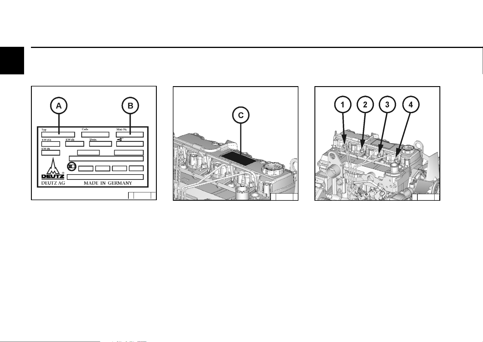
2.1.1 Company plate
© 43 870 0
The engine type A, engine number B and the
power data are stamped on the company plate.
The engine type and number must be stated
when purchasing spare parts.
2.1.2 Location of company plate
© 43 868 0
The company plate C is fixed to the valve
covering hood.
2.1.3 Cylinder numbering
© 43 869 0
The cylinders are counted consecutively,
starting from the flywheel.
© 2005
Page 11

2.1 Engine type
Engine description
2
© 2005
Page 12

2
Engine description
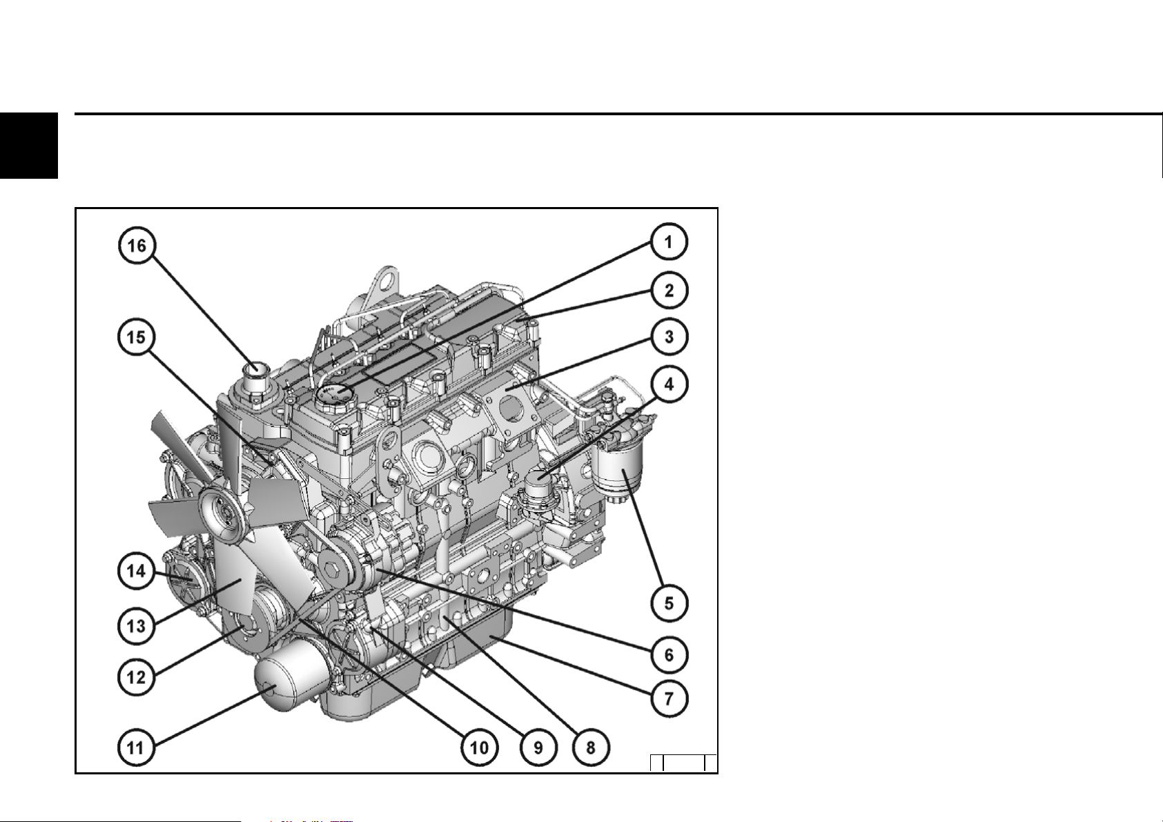
2.2.1 Operation side
Example: D 2008 L04
2.2 Engine illustration
1 Oil filler neck (valve cover)
2 Valve cover
3 Exhaust manifold
4 Fuel supply pump
5 Exchangeable fuel filter
6 Generator
7 Oil tray
8 Crankcase
9 Auxiliary drive possibility e.g. hydr. pump
10 Narrow V-belt
11 Exchangeable lube oil filter
12 V-belt pulley on crankshaft
13 Fan
14 Coolant pump, coolant inlet from cooler
15 Coolant outlet from engine to cooler
© 2005
© 43 862 0
Page 13
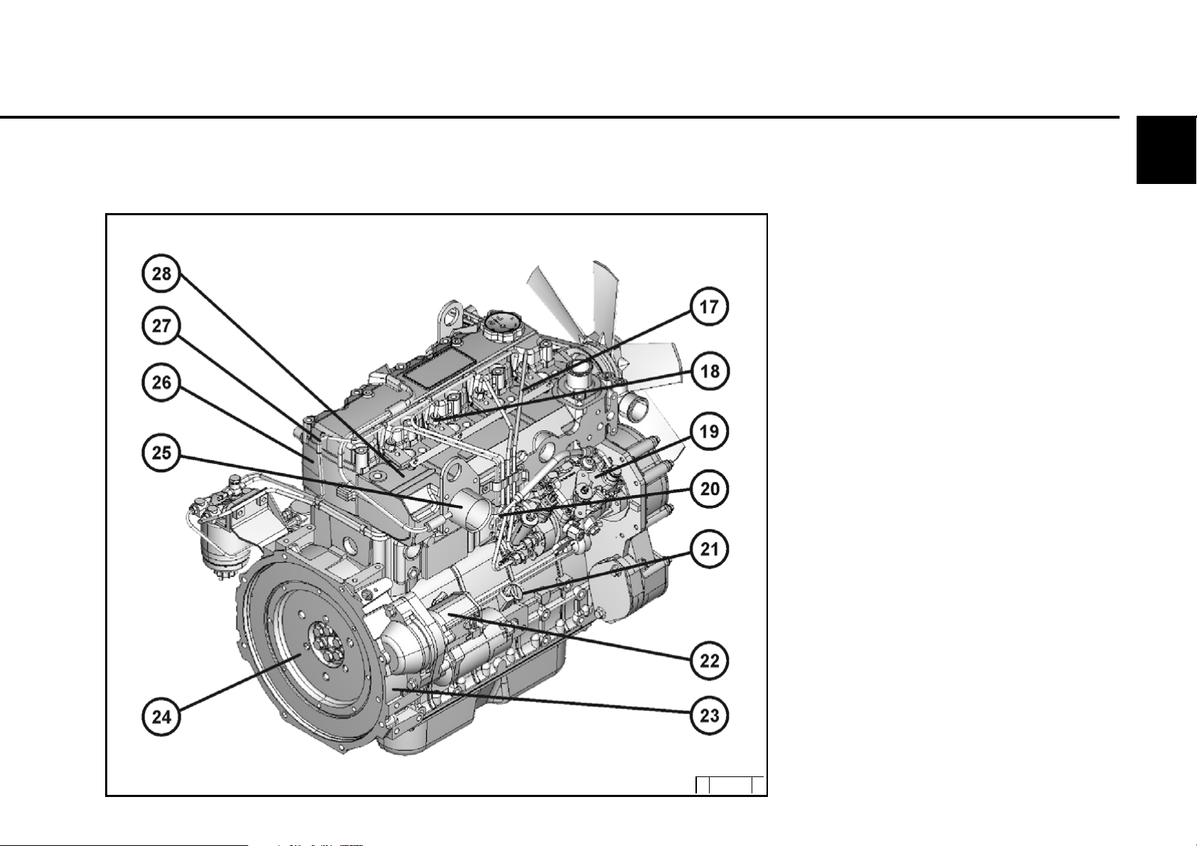
2.2 Engine illustration
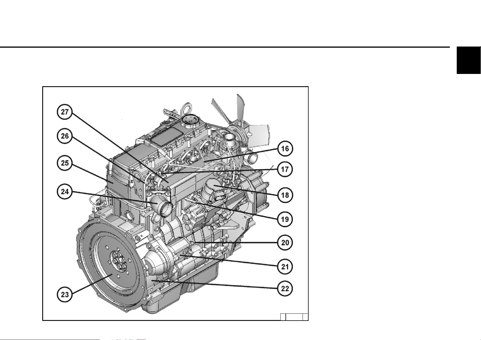
2.2.2Exhaust side
Example: D 2008 L04
Engine description
2
16 Injection line
17 Injection valve
18 Speed governor
19 Injection pump
20 Oil dipstick
21 Starter
22 Connection housing (SAE)
23 Flywheel with gear rim
24 Air intake pipe
25 Crankcase
26 Fuel return line
27 Charge air manifold from air filter
© 43 863 0
© 2005
Page 14
2
Engine description
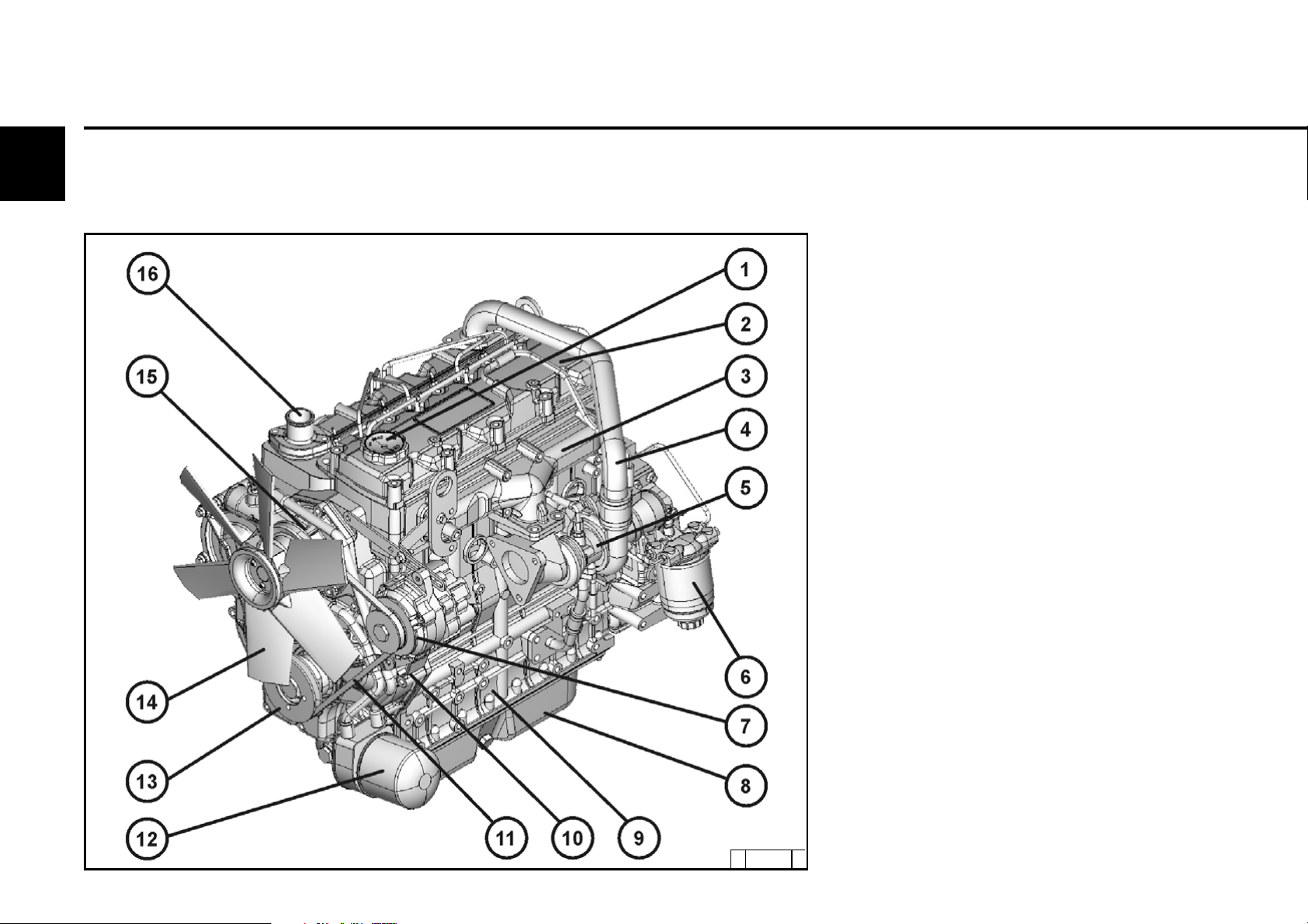
2.2.3 Operation side
Example: D 2009 L04
2.2 Engine illustration
1 Oil filler neck (valve cover)
2 Valve cover
3 Exhaust manifold
4 Fuel supply pump
5 Exchangeable fuel filter with water
separator
6 Generator
7 Oil tray
8 Crankcase
9 Auxiliary drive possibility e.g. hydr. pump
10 Narrow V-belt
11 Exchangeable lube oil filter
12 Crankshaft drive flange
13 Fan
14 Auxiliary drive possibility e.g. hydr. pump
15 Coolant pump, coolant inlet from cooler
16 Coolant outlet from engine to cooler
© 2005
© 43 864 0
Page 15
2.2 Engine illustration
2.2.4Exhaust side
Example: D 2009 L04
Engine description
2
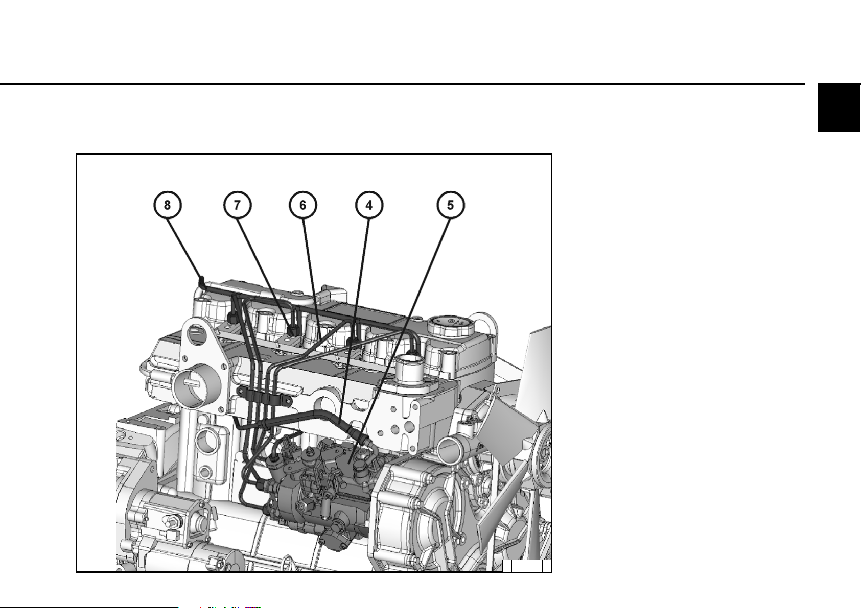
17 Injection line
18 Injection valve
19 Speed governor/injection pump
20 Injection line
21 Oil dipstick
22 Starter
23 Connection housing (SAE)
24 Flywheel with gear rim
25 Air intake pipe
26 Crankcase
27 Fuel return line
28 Charge air manifold from air filter
© 43 865 0
© 2005
Page 16
2
Engine description
2.2.5 Operation side
TD 2009 L04
2.2 Engine illustration
1 Oil filler neck
2 Valve cover
3 Exhaust manifold
4 Charge air line from turbocharger to
charge air manifold
5 Turbocharger
6 Exchangeable fuel filter with water
separator
7 Generator
8 Oil tray
9 Crankcase
10 Gearcase
11 Narrow V-belt
12 Exchangeable lube oil filter
13 V-belt pulley on crankshaft
14 Fan
15 Coolant pump, coolant inlet from cooler
16 Coolant outlet from engine to cooler
© 2005
© 43 866 0
Page 17
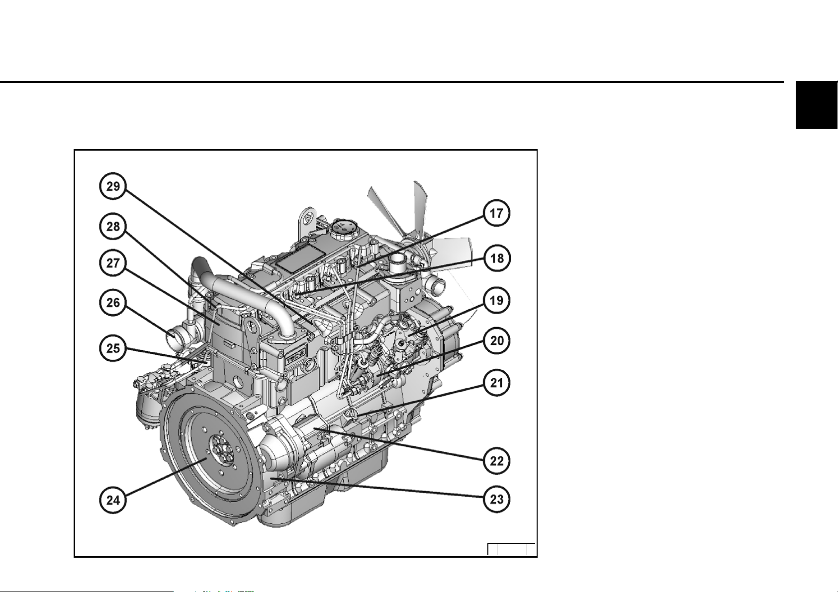
2.2 Engine illustration
2.2.6Exhaust side
TD 2009 L04
Engine description
2
17 Injection line
18 Injection valve
19 Speed governor
20 Injection pump
21 Oil dipstick
22 Starter
23 Connection housing (SAE)
24 Flywheel with gear rim
25 Fuel supply pump
26 Air intake pipe from air filter
27 Crankcase
28 Fuel return line
29 Charge air manifold
©43 867 0
© 2005
Page 18

2
Engine description
2.3.1 Fuel circuit
2.3 Fuel diagram
1 Fuel feed pump (connection line from
customer fuel container)
2 Fuel line from feed pump to fuel filter
3 Exchangeable fuel filter
© 2005
© 43 874 0
Page 19
2.3 Fuel diagram
Engine description
2
4 Fuel line from filter to injection pump
5 Injection pump
6 Injection line to injection valve
7 Injection valve
8 Fuel return line to customer fuel container
©43 873 0
© 2005
Page 20

3.1 Initial commissioning
3.2 Starting
3.3 Operation monitoring
3.4 Switching off
3.5 Operating conditions
Operation
3
© 2005
Page 21
Operation 3.1 Initial commissioning
3
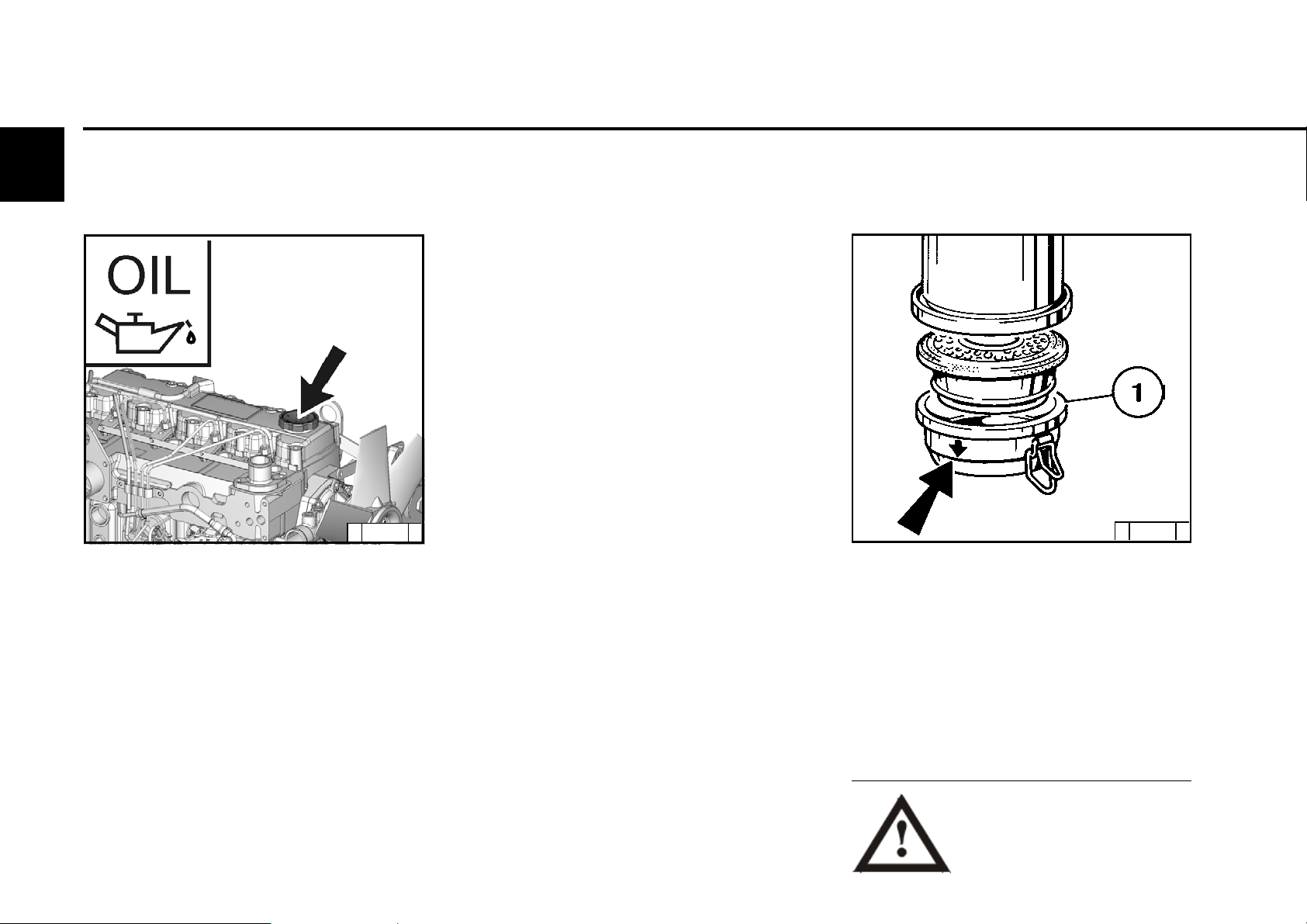
3.1.1 Engine oil filling
© 43 871 0
The engines are generally supplied without
oil filling.
Fill the engine with lube oil via the oil filler neck
(A).
For quality and viscosity of oil see 4.1.
3.1.1.1 Initial engine oil filling
z Fill the oil tray with oil up to the marking
"Max" on the oil dipstick (for oil filling
quantities see 9.1).
z Start the engine and run at a low idling
speed for approx. 2 minutes.
z Switch off the engine
z Check the oil level. If necessary, fill with oil
up to upper "Max" line marking.
3.1.2 Filling oil bath air filter with
engine oil
© 24 980 2
Fill the oil pan 1 of the oil bath air filter with
engine oil up to the arrow marking.
For quality and viscosity of oil see 4.1.
© 2005
Do not pour oil into the dust
collecting tank of the preseparator, if there is one
present.
Page 22
L
3.1 Initial commissioning Operation
3.1.3 Initial coolant filling
with cooler
z Fill honeycomb cooler with coolant up to
the marking " Max ".
z Also fill the supply hoses and the external
honeycomb cooler to coolant capacity (per
manufacturer specifications).
z Allow the engine to warm up until the
thermostat has opened (at approx. 86-90
°C ).
z Leave the engine running for approx. 2
minutes.
z Switch off the engine
z Check the oil level. If necessary, fill with
coolant up to upper " Max " line marking.
3.1.4 Fuel filling
3
FUE
© 26 398 0
Only use standard branded diesel fuel. For fuel
quality see 4.2. Depending on the outside
temperature, use either summer or winter diesel
fuel.
If the engine is not warmed up following
the initial filling, the oil level will be above
the "Max" marking on the oil dipstick.
Therefore, it is only possible to assess the
oil level after the warm up.
Only re-fuel when the engine is
not running!
Pay attention to cleanliness!
Do not spill any fuel!
© 2005
Page 23

Operation 3.1 Initial commissioning
3
3.1.5 Other preparations
z Check battery and cable connections,
see 6.6.1.
z Transportation eyelets
If installed, remove, see 6.6.3
z Trial run
After preparations carry out a short
trial run of approx. 10 min. Do not apply
load to the engine in doing this.
Work during and after the trial run
- Check engine for tightness.
z With engine not running
- Check oil level, see 6.1.2, if necessary
re-fill oil, see 3.1.1
- Check coolant level, see 3.1.3
- Re-tighten V-belts, see 6.5
z Running-in
It is recommended to check the oil level twice
a day during the running-in phase
(approx. 200 oh). After the running-in phase
checking once a day is sufficient.
3.1.6 Additional maintenance work
The following additional maintenance work is
to be carried out for the commissioning of
new and overhauled engines:
After 50-150 oh
z Change lube oil,
see 6.1.2
z Change oil filter cartridge,
see 6.1.3
z Change fuel filter cartridge,
see 6.2.1
z Check V-belt tension, if necessary
re-tighten, see 6.5.
z Check engine for tightness (leakages).
z Check engine bearing, re-tighten if
necessary.
© 2005
Page 24

3
© 2005
Page 25
Operation 3.2 Starting
3
3.2.1 Electrical starting
Before starting make sure that
there is nobody in the engine /
work machine danger area.
After repairs:
Check that all protective
equipment has been mounted
and all tools have been removed from the
vehicle.
When starting with heating flange do not use
any additional starting devices (e.g. injection
with start pilot). Danger of accidents!
Caution: Under no circumstances may the
engine be tested with a dismantled speed
governor:
Separate battery connections!
In cold ambient temperatures warm-up the
engine first - do not operate it straight away at
full load!
Start the engine for a maximum of 20 seconds
uninterrupted. If the engine does not start up, wait
for one minute and then repeat the starting
process.
If the engine does not start up after two starting
processes determine the cause as per fault table
(see 7.1).
© 2005
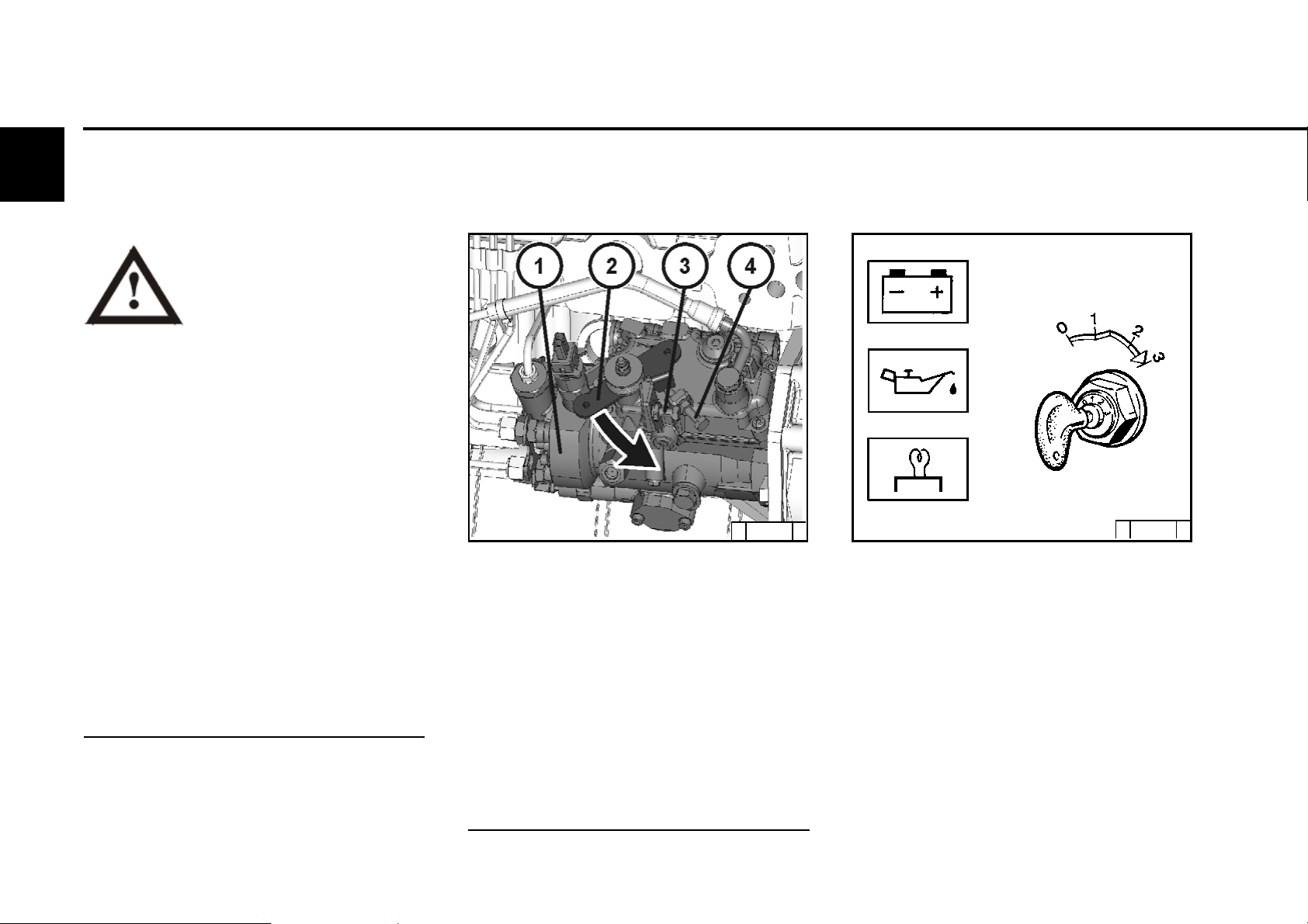
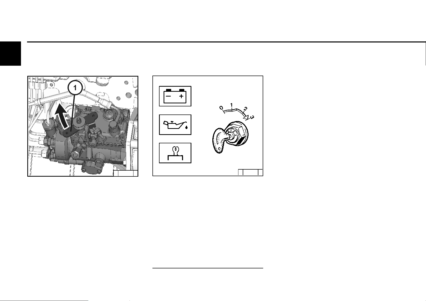
© 43 882 0
z Separate engine from devices which it powers,
by decoupling, as far as possible.
z Bring the speed adjustment lever 1 to the idling
position (idling setting screw 4).
z Bring the shutdown lever 2 to operating position
(direction of arrow, 3 max. speed stop).
Note: Setting screws 3+4 are factory set and
may not be changed
without cold start aid
© 25 746 2
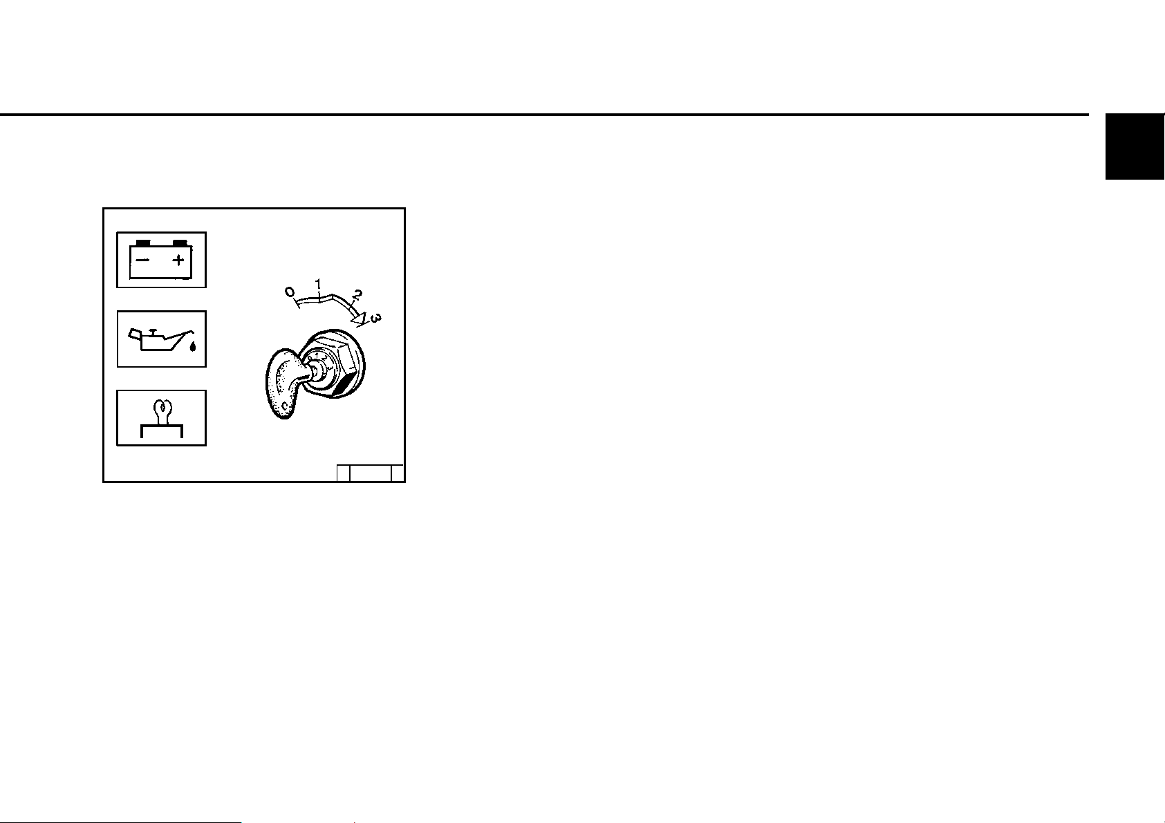
z Insert key.
- Step 0 - no operating voltage
z Turn key to the right.
- Step 1 = operating voltage
- Warning lights light up
z Push in the key and turn further to the
right against the spring load
- Step 2 = without function
- Step 3 = start
z Release key as soon as the engine
starts up
- Warning lights go out
Page 26
3.2 Starting Operation
with cold start aid
- heating flange
©25 746 2
z Insert key.
- Step 0 = no operating voltage
z Turn key to the right.
- Step 1 = operating voltage
- Warning lights light up
z Push in the key and turn further to the right
against the spring load
- Step 2 = pre-heating, hold for approx. one
minute
- Pre-heating light lights up
- Step 3 = start
z Release key as soon as the engine starts up.
- Warning lights go out
3
© 2005
Page 27
Operation 3.3 Operation monitoring
3
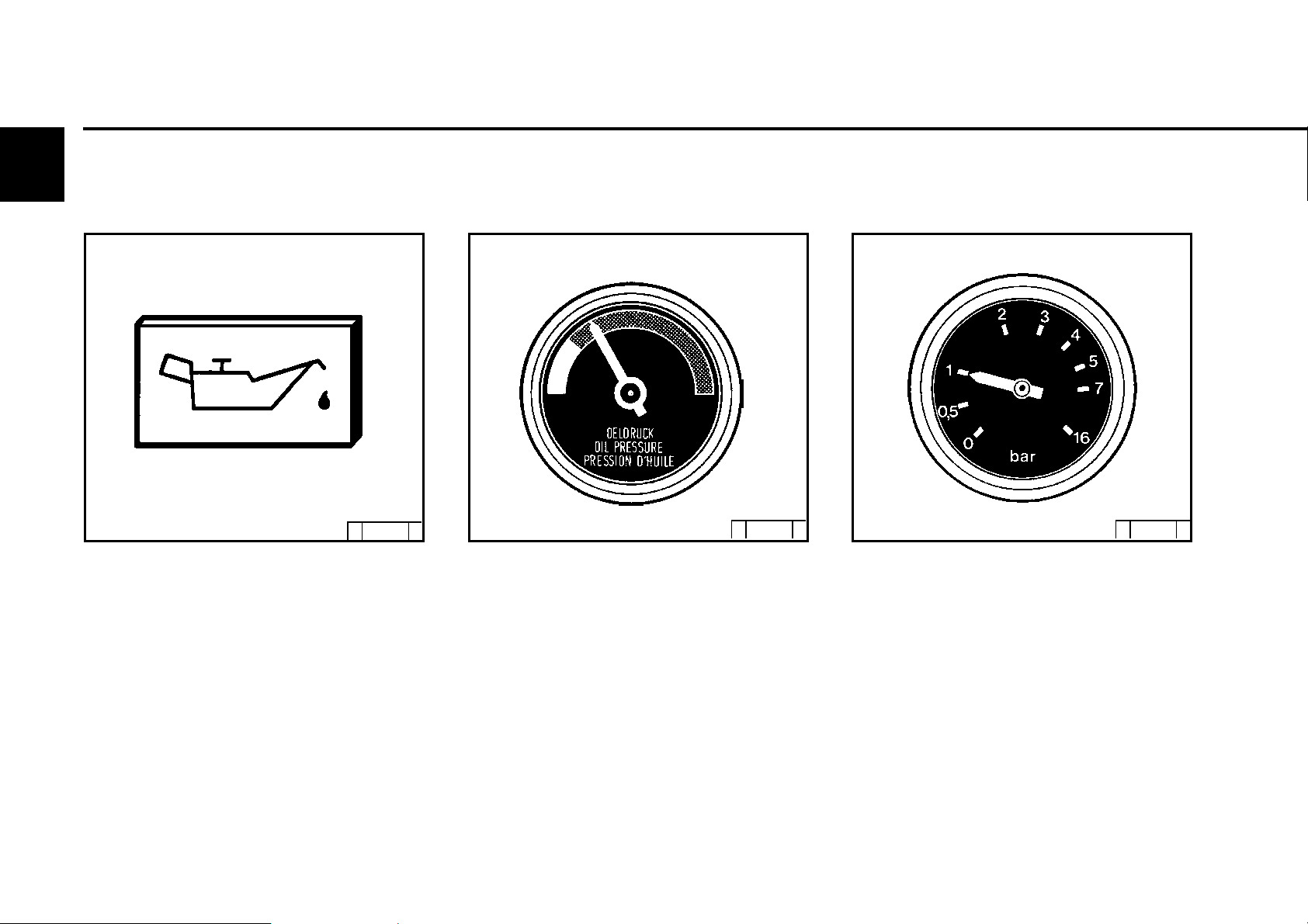
3.3.1 Engine oil pressure
Oil pressure warning light
© 25 752 1
z Oil pressure warning light lights up when
operating voltage is switched on, and when
the engine is not running.
z Oil pressure control light must be extinguished
during engine operation.
Oil pressure display
© 25 753 0 © 25 754 0
z Needle must be in the green field in the total
operating range.
Oil pressure gauge
z Needle of oil pressure measuring instrument
must indicate the minimum oil pressure (see
9.1).
© 2005
Page 28
3.3 Operation monitoring Operation
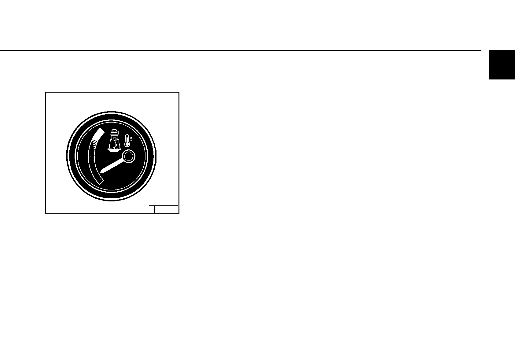
3.3.2 Engine temperature
Temperature display
©24 985 0
z The needle of the temperature display should
always be in the green area, and only as an
exception in the yellow/green area. If the
needle rises into the orange area the engine is
getting too hot. Switch off the engine and
determine the cause as per fault table (see
7.1).
3
© 2005
Page 29
Operation 3.4 Switching off
3
3.4.1 Mechanical switching-off
© 43 872 2
z Position the speed adjustment lever 1 to low
speed.
z Turn the speed adjustment lever 1 in the
direction of the arrow until it reaches idle stop.
Charge warning light and oil pressure warning
light light up after the engine has not been
running.
z Turn the key to the left (to step 0) and remove.
Warning lights go out
3.4.2 Electrical switching off
(ignition key)
© 25 746 0
z Turn the key to the left (to step 0) shutdown
magnet switches the engine off and remove.
Warning lights go out
© 2005
If possible, do not suddenly switch-off engine
from full-load operation.
Page 30

3.5 Operating conditions Operation
3.5.1 Winter operation
z Lube oil viscosity
- Select the viscosity (SAE class) according
to ambient temperature when starting the
engine, see 4.1.2.
- Observe shorter oil change times when
operating under -10 °C, see 6.1.1.
z Diesel fuel
- Under 0 °C use winter fuel, see 4.2.2.
z Additional maintenance work
- Drain the liquid sludge from the fuel container
weekly. (Loosen the sludge bleed screw)
- If necessary, adjust the oil filling of the oil bath
air filter and engine oil to the outside
temperature.
- At temperatures under -20 °C, possibly after
the starter has slowed-down, occasionally
lubricate the gear rim on the flywheel with
cold resistant grease through the pinion hole.
(e.g. Bosch grease FT 1 V 31).
3
z Battery
- A well charged battery is a prerequisite
for a good cold start, see 6.7.1.
- Heating the battery to approx. +20 °C
(dismantle and store in a warm room) lowers
the starting limit temperature by 4-5 °C.
© 26 248 0
z Cold start aids
- When there is a frost, start the engine with
heating flange if necessary, see 3.2.1.
This does not only lower the starting limit
temperature, but also eases starting at
temperatures which do not actually require
a starting aid.
© 2005
Page 31
3
Operation 3.5 Operating conditions
3.5.2 High ambient temperature
high altitude
z When the altitude or ambient temperature
increases, the air density decreases. This
impairs the maximum engine performance,
exhaust quality, temperature level and, in extreme cases, the starting performance. For
transient operation, usage up to 300 m and
25 °C is permissible. When using the engine
under adverse conditions (high altitude or high
temperatures) it is necessary to reduce the
amount of fuel injected and with it the engine
power.
z In case of doubt regarding engine usage, ask
your engine or equipment supplier whether
necessary fuel stop reduction has been carried
out in the interest of operational safety, service
life and exhaust quality (smoke), or contact
your DEUTZ SERVICE.
© 25 901 1
© 2005
Page 32

4.1 Lube oil
4.2 Fuel
4.3 Coolant
Operating substances
4
© 2005
Page 33
Operating substances 4.1 Lube oil
4
4.1.1 Quality
Lube oils are classified by Deutz according
to their performance capability into quality
classes. Oils according to other comparable
specifications can be used.
Recommended oils:
Deutz DQC II DQC I II *+DQC IV
ACEA E3-96/E5-02/ E4-99/
E7-04 E6-04
API CH-4/CG-4 -
CI -4
DHD DHD-1
DQC III * see chap. 6.1.1.2
DQC IV
The exact assignment of permissible oil quality
and oil change intervals is listed in chapter
6.1.1.
#
only fully synthetic oils
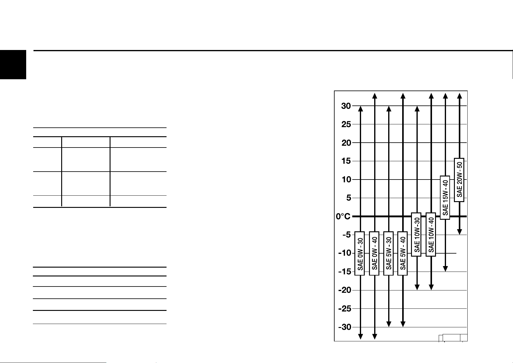
4.1.2 Viscosity
Generally, multi-viscosity oils are should be
used. Single-viscosity oils can also be used
in enclosed, heated spaces at temperatures
>5° C.
Since lube oil changes its viscosity (viscidity)
#
depending on temperature, the ambient
temperature of the location of engine operation
is decisive for the selection of viscosity class
(SAE class).
Refer to the oil viscosity diagram on the right
to achieve optimal operating proportions.
Falling below the temperature limits
occasionally can impair the cold starting ability,
but will not lead to engine damages.
In order to minimise wear, the operating limits
should not be exceeded over a long period of
time.
Synthetic lube oils are advantageous due to
their greater temperature and oxidisation
stability.
Minimum requirement:
Deutz DQC I
ACEA E2-96
API CF/CF-4
*For oil change intervals see 6.1.1
For oil filling amounts see 9.1
© 2005
only with pre-heating
30 298 1
© 30 298 1
Page 34
4.2 Fuel Operating substances
4.2.1 Quality
Use standard diesel fuels with a sulphur content
of less than 0.5 %. If the sulphur content is higher,
the oil change intervals must be reduced (see
6.1.1).
The following fuel specifications are
permitted: (see TR 0199-99-3005)
The Technical Circular provides details on
fuel specifications and can be obtained from
the DEUTZ Service Organisation.
● Diesel fuel
- EN 590
- ASTM D 975-88 grade no. 1-D and 2-D
- NATO code F-54
- JIS K2204 grade 1 and 2
●●
● Light fuel oils
●●
- DIN 51603
- ASTM D 396 grade no. 1 and 2
- BS 2869 class A 2
The certification measurements for the
observance of legal emission limits are carried
out with the test fuels defined by legislation.
These correspond with the diesel fuels
described in section 1 in accordance with D
EN 590 and ASTM D 975. Emission values
cannot be guaranteed with the other fuels
described in this circular
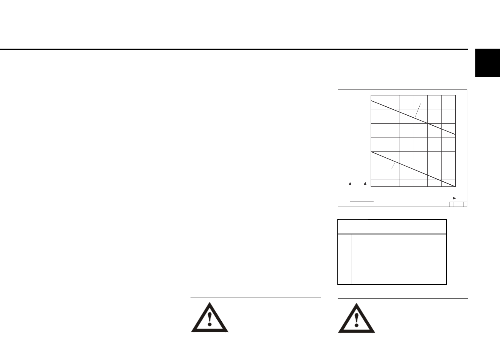
4.2.2 Winter fuel
At low temperatures paraffin discharges
can lead to blockages in the fuel system and
cause operating faults. Use winter fuel at
outside temperatures under 0 °C (to -15 °C)
(generally offered by petrol stations in good
time before the cold season begins).
Frequently it is possible to buy diesel fuel with
additives, which has an operational
temperature of up to approx. -20 °C ("Super
diesel“).
● Paraffin should be added at temperatures
below -15 °C or -20 °C. The mixing ratios
required are as per the diagram on the right.
Íf it is necessary to use summer diesel fuel
under 0 °C, paraffin can also be added by up
to 60% as per the diagram on the right.
Generally, sufficient resistance to cold can
also be achieved by adding a flow ameliorant
(fuel additive). For questions regarding this
please contact your DEUTZ Service
Diesel fuels must never be
mixed with petrol (normal and
super)!
+32
+23
+14
+ 5
- 4
- 13
- 22
°F
0
I
- 5
- 10
- 15
- 20
- 25
II
- 30
0 10 20 30 40 50 60 %
°C
A
Diagram key:
I Summer diesel fuel
I I Winter diesel fuel
A Outside temperature
B Paraffin mixing proportion
Only carry out mixing in the
tank! First pour in the necessary
amount of paraffin, then the
diesel fuel.
4
B
' 26441 1
© 2005
Page 35
Operating substances 4.3 Coolant
4
4.3.1 Water quality for coolant
The water may not fall short of or exceed the
following values.
A test case can be requested from DEUTZ
Service under the order no. 1213 0382 for
checking your water quality.
Analysis values min. max.
ph value at 20 °C 6.5 8.5
Chloride ion content[mg/dm3] - 100
Sulphate ion content[mg/dm3] - 100
Total hardness [°dGH] 3 20
* Carbonate hardness proportion of total
hardness min 3 dGH
4.3.2 Coolant preparation
Particular attention should be paid to preparing
and inspecting the coolant in liquid-cooled
engines, as otherwise corrosion, cavitation
and freezing damages can occur on the
engine.
Preparation of the coolant involves mixing a
cooling system preservative to the cooling
water.
The cooling system must be monitored
regularly, see 5.1. This includes checking the
concentration of the cooling system
preservative, as well as inspecting the coolant
level.
The inspection of the concentration of cooling
system preservative can be carried out with
standard testing devices.
(Example: gefo glycomat R ).
4.3.3 Cooling system preservative
Using the cooling system preservative, order
no. 01011490/ 01016416/12211500 (nitrite,
amine and phosphate free, available in 5/ 20/
210 litre containers), provides effective
protection against corrosion, cavitation and
freezing.
The cooling system preservative in the coolant
must not fall below or exceed the following
concentrations:
Cooling system Water Cold protection
prot.proportion proportion to
min. 35 % 65% -22 °C
40 % 60% -28 °C
max. 45 % 55% -35 °C
For filling amounts see the table overleaf in
combination with the information in chapter
9.1.
The use of other cooling system preservatives, e.g. chemical corrosion preservatives,
is possible in exceptional cases, consult
DEUTZ Service.
Contact your local waterworks for information
regarding the water quality.
© 2005
Mixing cooling system
preservatives of a nitrite
basis with substances of an
amine basis forms harmful
nitrosamines.
Order the cooling system preservative from:
DEUTZ AG
Cooling system preservatives
must be disposed of in an
environmentally friendly manner.
Page 36

Maintenance
5.1 Maintenance schedule
5.2 Standard maintenance schedule
5.3 Maintenance diagram
5.4 Maintenance work carried out
5
© 2005
Page 37
Maintenance 5.1 Maintenance schedule
5
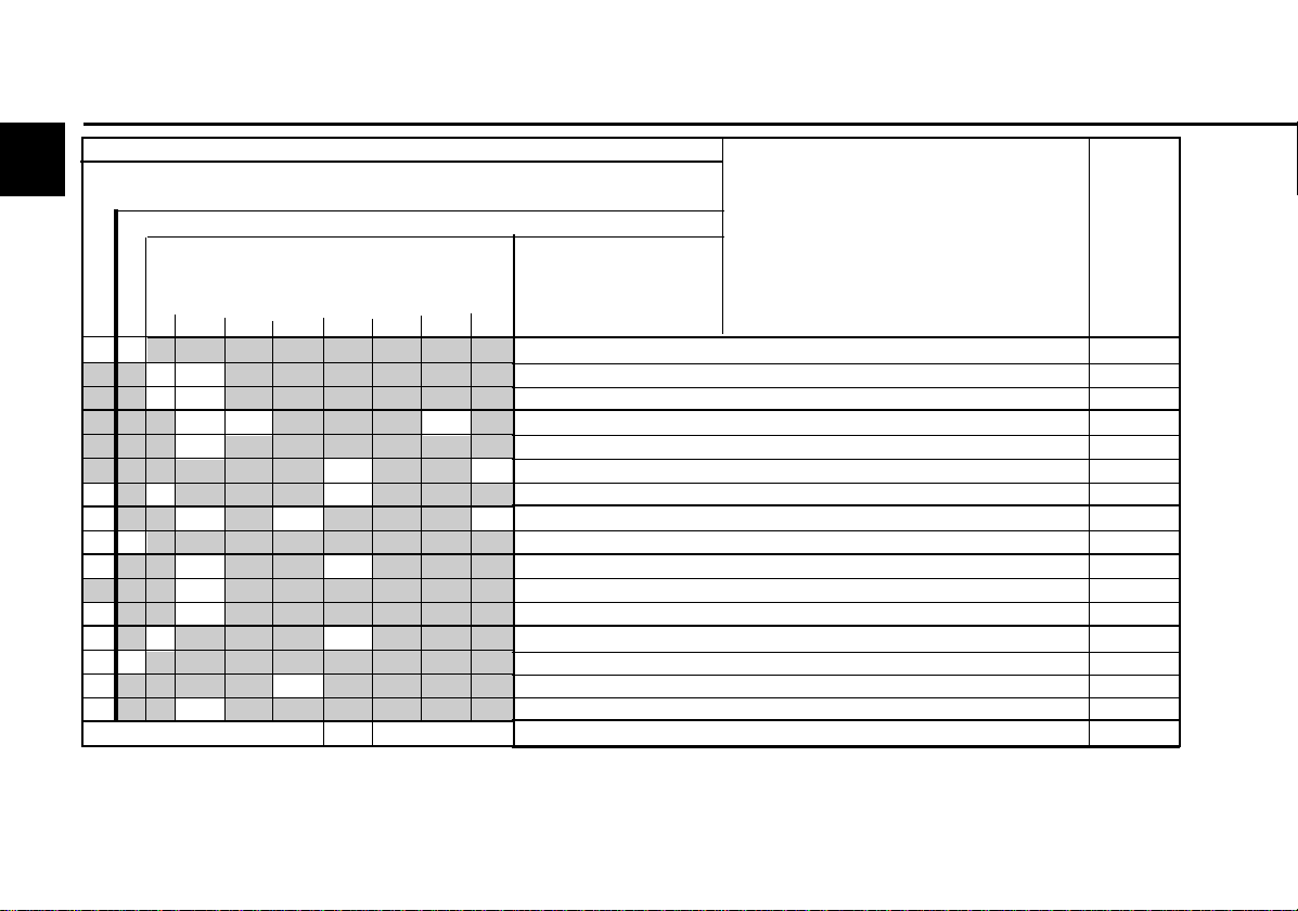
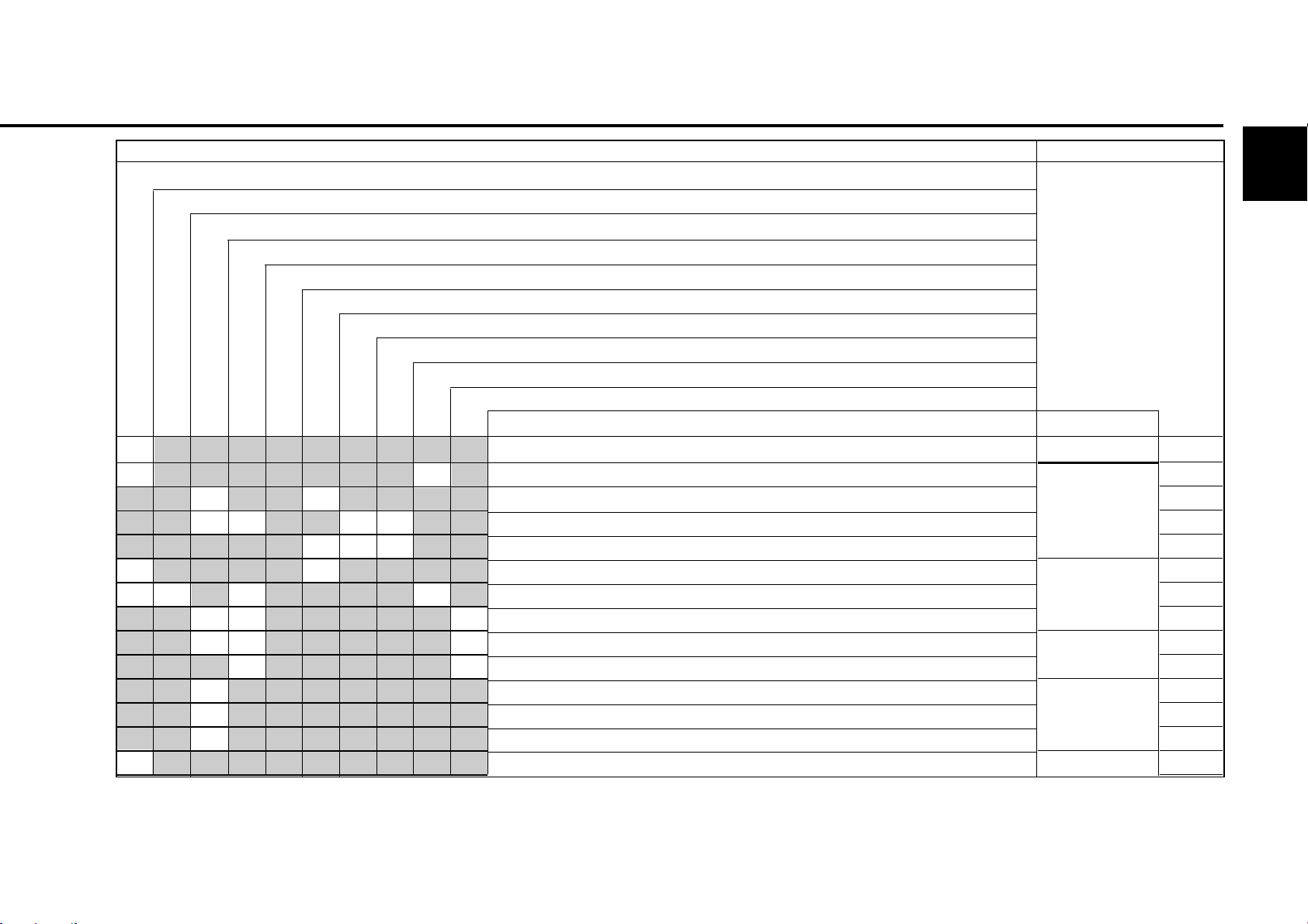
check= l set= m clean= s renew= n
check 2x daily before or during the 1st trial run during the running-in phase or
when commissioning new and overhauled engines.
every 10 oh or daily
in operating hours (oh) every
E 10 E20 E25 E30 E40 E45 E60
250 500 1000
ll
°n°
n
°n°
n
ln n
n
l s n
lln n
ll
ll n
l
ll
ll n
ll
ll
ll
2000 3000 6000
nn
n
Years
12
Industrial engines
The engine maintenance times given are
maximum permissible job times. Depending on
the usage circumstances, shorter maintenance
times may be necessary. Observe the instruction
manual of the equipment manufacturer.
# Maintenance only to be carried out by authorised
Activity
Lube oil level, if necessary re-fill 6.1.2/3.3.4
Lube oil
( ° oil change intervals depending on type of engine use)
Oil filter cartridge (at each lube oil change) 6.1.3
Fuel diaphragm pump 6.2.4
Fuel filter cartridge 6.2.1
Injection valve
Fuel pre-cleaner / Fuel pre-filter* (change filter insert if necessary) 4.2
Coolant (additive concentration) 4.3.1/ 2/
Coolant level –
Intake air filter
Battery and cable connections 6.7.1
Engine monitoring, warning system 3.3
V-belts (if necessary, re-tighten or renew ) 6.5.1
Engine for tightness (visual inspection for leaks). –
Engine bearing (renew in case of damage) 9.2
Fixings, hose connections / clamps (renew in case of damage) –
Part overhauling #
(if available, as per maintenance display)
service personnel
, see TR 0199-99-3002 6.1.1/ 6.1.2
Section
6.4.3 /6.4.4
#
* If the warning system (light/siren) is activated, the fuel pre-filter must be emptied immediately.
© 2005
Page 38

5.1 Maintenance schedule Maintenance
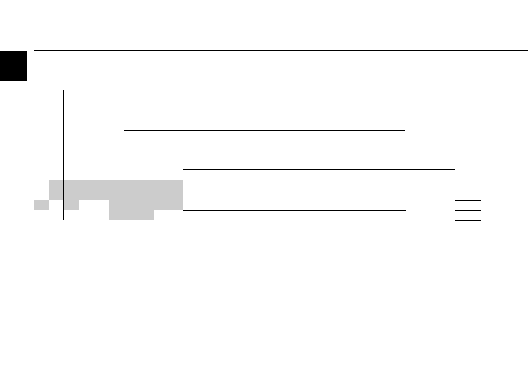
check= l set= m clean= s renew= n
max. permissible job times in operating hours (oh) every
check 2x daily before or during the 1st trial run during the running-in phase or
when commissioning new and overhauled engines.
every 10 oh or daily
in operating hours (oh) every
250 500 1000
3000 6000
n
Years
12
Activity
Injection valve
Enhancements or modifications
for engines with EPA acceptance
The engine maintenance times given are maximum
permissible job times. Depending on the usage
circumstances, shorter maintenance times may
be necessary. Observe the instruction manual of
the equipment manufacturer.
# Maintenance only to be carried out by authorised
service personnel
5
Section
#
© 2005
Page 39

Repairs 5.2 Standard maintenance schedule
5.2.1 Standard maintenance schedule
5
Intervals Service Activity Execution by: Comments
at/after schedule
50 oh E 10 after commissioning and E 45-E60 authorised specialists
daily E 20 daily inspection round operator
250 oh E 25 inspection authorised specialists
500 oh E 30 extended inspection authorised specialists
1000 oh E 40 intermediate overhaul authorised specialists
2000 oh E 45 intermediate overhaul authorised specialists
3 000 oh E60 part overhaul authorised specialists
© 2005
Page 40
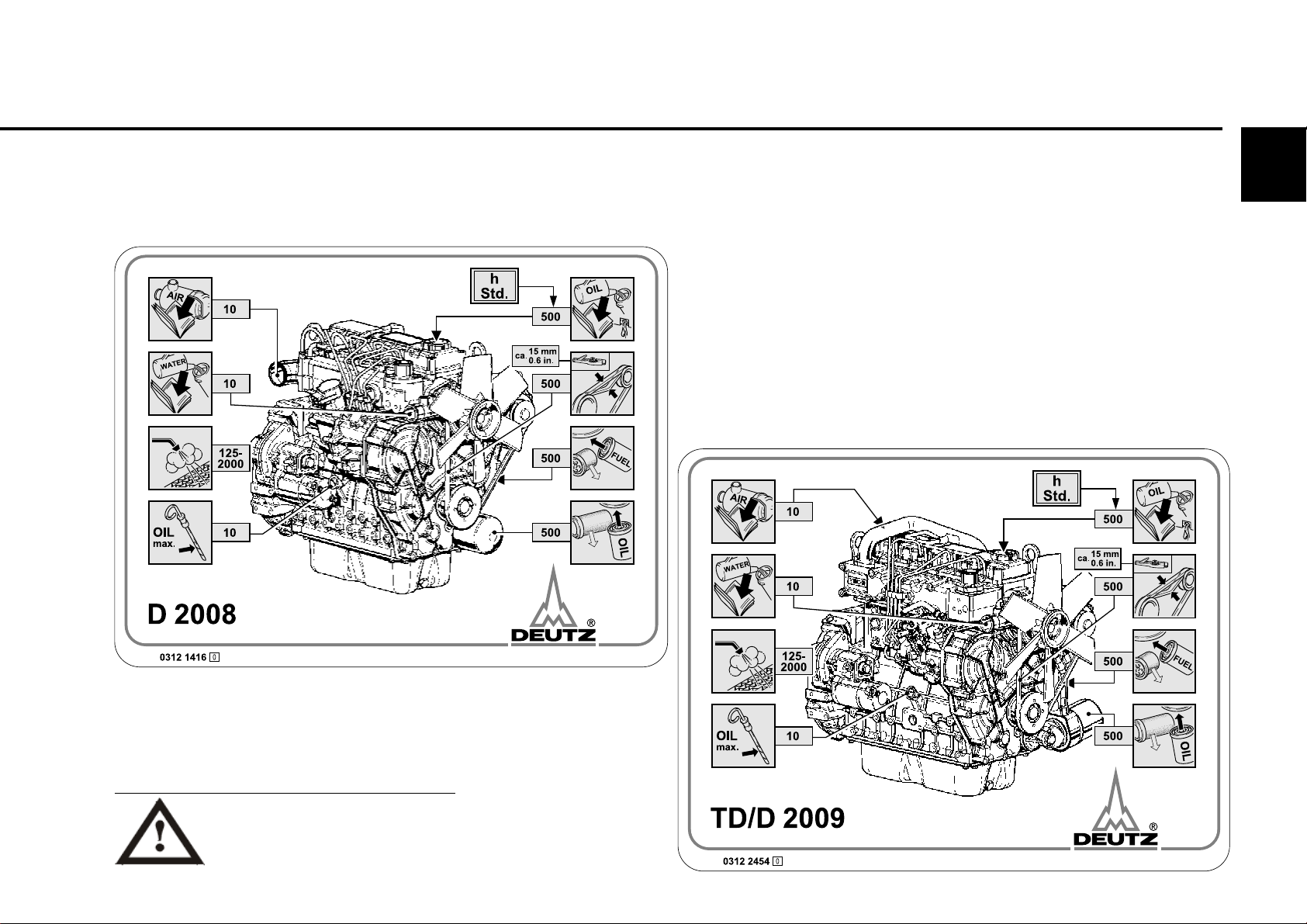
5.3 Maintenance diagram Maintenance
The maintenance diagram shown on this page is supplied with every engine in self-adhesive form. It should be stuck onto a well visible location
on the engine or equipment.
Check that this is the case!
If not, request a replacement from your engine or equipment supplier!
The maintenance schedule is decisive for standard maintenance, see 5.1.
5
All maintenance work should
only be carried out when the
engine is not running.
© 2005
Page 41

Maintenance
5.4 Maintenance work carried out
5
Op. hrs.
50-150
125
375
625
875
1125
1375
1625
1875
Date Signature / stamp
*
Op. hrs. Signature / stamp
Date
-
250
500
750
1000
1250
1500
1750
2000
© 2005
2115
2375
2625
2250
2500
2750
* after commissioning new and overhauled engines
The maintenance work carried out methodically can be recorded in the table and confirmed.
Page 42

5.4 Maintenance work carried out Maintenance
Op. hrs.
2875
3125
3375
3625
3875
4125
4375
4625
4875
Date
Signature / stamp Op. hrs. Date
3000
3250
3500
3750
4000
4250
4500
4750
5000
Signature / stamp
5
5125
5375
5625
5250
5500
5750
The maintenance work carried out methodically can be recorded in the table and confirmed.
© 2005
Page 43

Maintenance
5.4 Maintenance work carried out
5
Op. hrs.
5875
6125
6375
6625
6875
7125
7375
7625
7825
Date Signature / stamp
Op. hrs. Signature / stamp
6000
6250
6500
6750
7000
7250
7500
7750
8000
Date
© 2005
8125
8375
8625
8250
8500
8750
The maintenance work carried out methodically can be recorded in the table and confirmed.
Page 44

5.4 Maintenance work carried out Maintenance
Op. hrs.
8875
9125
9375
9625
9875
10125
10375
10625
10875
Date
Signature / stamp Op. hrs. Date
9000
9250
9500
9750
10000
10250
10500
10750
11000
Signature / stamp
5
10125
10375
10625
11250
11500
11750
The maintenance work carried out methodically can be recorded in the table and confirmed.
© 2005
Page 45

Maintenance
5.4 Maintenance work carried out
5
Op. hrs.
Date Signature / stamp
Op. hrs. Signature / stamp
Date
© 2005
Page 46

Care and maintenance work
6.1 Lubrication system
6.2 Fuel system
6.3 Cooling system
6.4 Combustion air filter
6.5 Belt drive
6.6 Setting work
6.7 Add-on components
6.8 Engine cleaning
6
© 2005
Page 47

6
Care and maintenance work 6.1 Lubrication system
6.1.1 Oil change intervals
z The oil change times depend on the engine
application and the quality of the lube oil.
z If the oil change times are not reached within a
year, the oil change should be carried out at least
1x yearly.
z The following conditions apply for the table
- Sulphur content max. 0.5% of weight of diesel
fuel.
- Constant ambient temperature to
- 10 °C (+14 °F).
z The oil change times should be halved for fuels
with a sulphur content of > 0.5 to 1% or a
constant ambient temperature below -10 °C
(+14 °F).
z For fuels with a sulphur content higher than 1%
ask your responsible
service representative.
Carry out oil changes on warm engine when the
engine is not running (lube oil temperature approx.
© 2005
80 °C).
Page 48

6.1 Lubrication system Care and maintenance work
6.1.1.1 Lube oil change intervals
Lube oil quality
Minimum Recommended oils:
requirement
Deutz lube oil quality class DQC I DQC II DQC II DQC IV
AC EA sp ecif icat ion E2-96 E3-96/E5-02/E7-04 E4-99/E6-04 E4-99/E6-04
API specification CF/CF-4 CH-4/CG-4 - w or l d wi d e s p ec if ic a t io n - DHD-1 - special DEUTZ release list - - see 6.1.1.2 only fully synthetic
Standard lubricant code designation EO... EO...C - -
for building machines and building vehicles EO...A, EO...B
Engine Lube oil change intervals in oh
Series Engine version
normal normal normal normal
oil demands
6
D 2008
TD / D 2009 Charged and
* Under particularly severe ambient conditions the oil change intervals should be halved.
This includes ambient temperatures greater than 35° C (95° F), high dust exposure, power factor over 70% or high dynamic stress. In case
of doubt, please ask your service representative.
Naturally aspirated engines
naturally aspirated engines
250* 500* 500* 500*
500 500 500 500
© 2005
Page 49

6
Care and maintenance work 6.1 Lubrication system
6.1.1.2 Release list DEUTZ lube oil quality level
DQC II
Manufacturer Lube oil type SAE class Availability
DEUTZ DEUTZ oil TLX-10W40FE 10W-40 Europe
ADDINOL ADDINOL Super Truck MD 1048 10W-40 Europe, Asia
ADDINOL Ultra Truck MD 0538 5W-30 Europe, Asia
AGIP Agip Sigma Ultra TFE 10W-40 worldwide
Autol Valve Ultra FE 10W-40 Germany
ARAL Aral MegaTurboral 10W-40 worldwide
Aral SuperTurboral 5W-30 worldwide
AVIA TURBOSYNTH HT-E 10W-40 Germany
BAYWA BayWa Super Truck 1040 MC 10W-40 South Germany
BayWa Turbo 4000 10W-40 South Germany
BP OIL International BP Vanellus E7 Plus 10W-40 Europe
BP Vanellus E7 Supreme 5W-40 Europe
Castrol Castrol SYNTRUCK 5W-40 Europe, North America, Brazil
Argentina, Australia, South Africa
Castrol DYNAMAX 7.5W-40 Europe, North America, Brazil
Argentina, Australia, South Africa
CEPSA EUROTRANS SHPD 10W-40 Spain, Portugal
CHEVRON Chevron Delo 400 Synthtic 5W-40 North America
DEA DEA Cronos Synth 5W-30 Germany, Europe
DEA Cronos Premium LD 10W-40 Germany, Europe
DEA Cronos Premium FX 10W-40 Europe
© 2005
Page 50

6.1 Lubrication system Care and maintenance work
ESSO Essolube XTS 501 10W-40 Europe
FUCHS EUROPE Fuchs Titan Cargo MC 10W-40 worldwide
Fuchs Titan Unic Plus MC 10W-40 worldwide
MOBIL OIL Mobil Delvac 1 SHC 5W-40 Europe, SE Asia, Africa
Mobil Delvac 1 5W-40 worldwide
Mobil Delvac XHP Extra 10W-40 Europe, SE Asia
Lube oil refinery Wintershall TFG 10W-40 Europe
Salzbergen
Shell International Shell Myrina TX / 5W-30 Europe, code
Shell Rimula Ultra country specific, varies
Shell Myrina TX / 10W-40 Europe, code
6
Shell Rimula Ultra country specific, varies
Texaco Ursa Super TDX 10W-40 10W-40 Europe
Ursa Premium FE 5W-30 5W-30 Europe
TOTAL TOTAL RUBIA TIR 8600 10W-40 worldwide
EXPERTY
10W-40 worldwide
This table will be extended if necessary.
© 2005
Page 51

6
Care and maintenance work 6.1 Lubrication system
6.1.2 Checking oil level /
changing engine oil
6.1.2.1Checking oil level 6.1.2.2Changing engine oil
z Oil level on switched off engine, check
z Position the engine or vehicle so as to be level.
z Extract oil dipstick.
z Wipe with a fibre-free, clean cloth.
z Insert until it stops and extract again.
"MAX"
z Check oil level and re-fill to
- If the oil level lies just above the "MIN"
line marking, re-filling is necessary.
The oil level may not fall short of the "MIN" line
marking.
© 2005
if necessary.
© 26 022 0© 25 729 0
z Warm up the engine
z Position the engine or vehicle so as to be level.
- lube oil temperature approx. 80 °C.
z Switch off the engine.
Caution when draining
hot oil: danger of scalding !
Collect the used oil, do not
allow to seep into floor!
Dispose of according to
instructions!
© 26 023 0
z Position oil drip cup under the engine.
z Unscrew oil drain screw.
z Drain off oil.
z Screw in oil drain screw with new sealing ring
and tighten. (For tightening torque see 9.2).
z Pour in lube oil
- For quality / viscosity data see 4.1.
- For filling amounts see 9.1.
z Check oil level, see 6.1.2.1
Page 52
6.1 Lubrication system Care and maintenance work
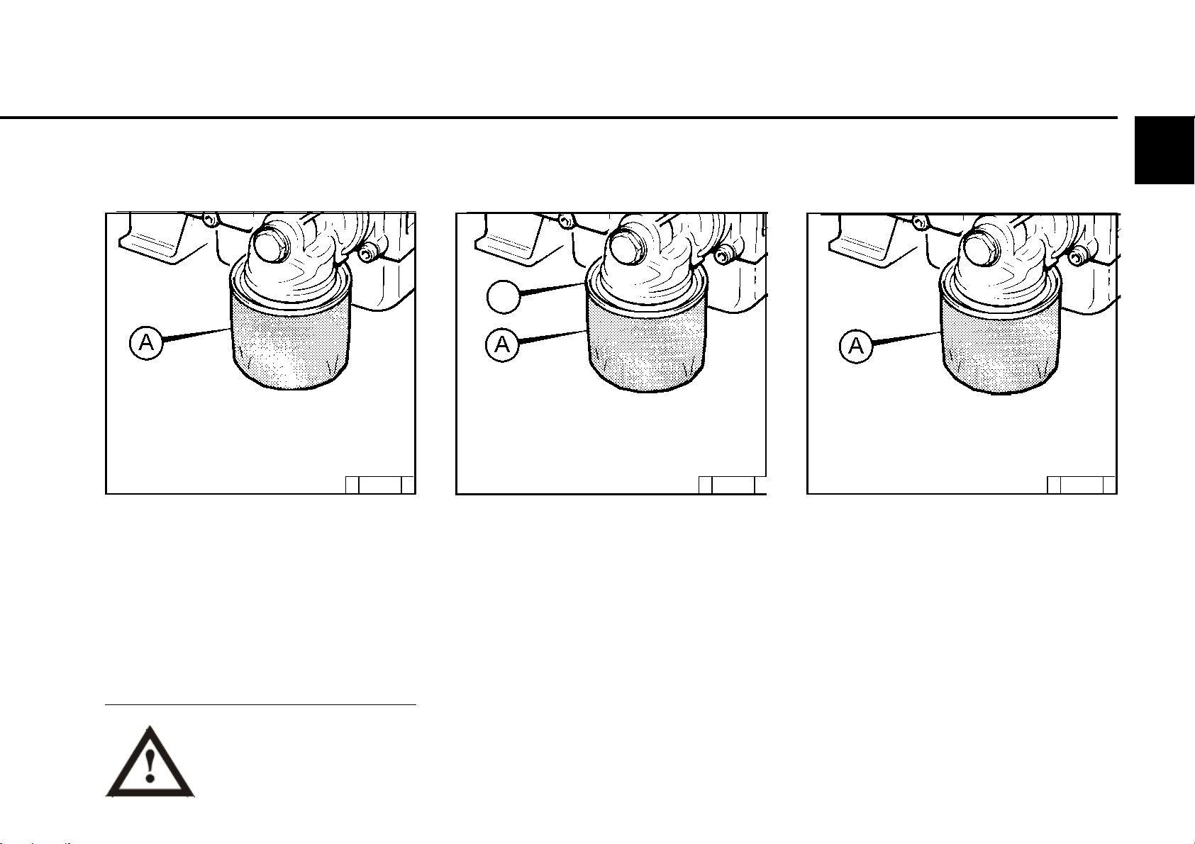
6.1.3 Changing oil filter
B
6
G
C
© 43 917 0 © 43 918 0
z Loosen the lube oil filter cartridge A in the
direction of the arrow with a standard tool and
unscrew.
z Collect any oil which may run out.
Careful with hot oil: Danger of
scalding!
C
z Clean the sealing surface B of the filter support
for any possible dirt.
z Lightly oil the rubber seal of the new lube oil
cartridge A.
F
© 43 919 0
z Screw on the cartridge in the direction of the
arrow by hand until the seal makes contact.
z Tighten the lube oil filter cartridge A with one
more half turn.
z Check oil level, see 6.1.2.
z Check oil pressure, see 3.3.1.
z Check the seal of the lube oil cartridge for
tightness.
© 2005
Page 53

6
Care and maintenance work 6.2 Fuel system
6.2.1 Changing fuel filter
© 25 880 0 © 25 882 0© 25 881 0
z Close fuel stopcock.
z Loosen fuel filter cartridge with standard tool
and unscrew.
z Collect fuel which runs out.
No open fire when working on
the fuel system!
Do not smoke!
© 2005
z Clean the sealing surface of the filter support
for any possible dirt.
z Lightly oil the rubber surface of the new fuel
filter cartridge or wet with diesel fuel.
z Screw on the cartridge by hand until the seal
makes contact.
z Tighten the fuel filter cartridge with one more
half turn.
z Open fuel stopcock.
z Check for tightness.
It is not necessary to bleed the fuel system.
Page 54

6.2 Fuel system Care and maintenance work
6.2.2 Bleeding fuel system
© 43 879 0
z Position collecting vessel underneath filter.
z Open fuel stopcock.
z Loosen bleed screw 1
z Turn the lever on the fuel pump 2 until the fuel
escapes from the bleed screw 1 without
bubbles.
z Tighten bleed screw 1
zDispose of the fuel from the collecting vessel
in an environmentally sound manner.
z Check tightness after commissioning.
6.2.3 Draining water from fuel
system
© 43 880 0
z Position collecting vessel underneath filter.
z Loosen drainage screw 1
z Drain water from the drainage screw 1.
z Tighten drainage screw 1.
zDispose of the water from the collecting vessel
in an environmentally sound manner.
z Check tightness after commissioning.
6.2.4 Changing fuel diaphragm
pump
© 43 878 0
z Position collecting vessel underneath fuel
diaphragm pump 3.
z Loosen screw on fuel line 1 to filter support and
separate from fuel diaphragm pump 3.
z Loosen screw 2.
z Remove fuel diaphragm pump 3.
z Install fuel diaphragm pump 3 with new sealing
ring 4.
z Tighten fuel line 1 to filter support.
z Bleed fuel system, see 6.2.2
z Check tightness after commissioning.
If possible, do not let the tank run
empty! No open fire when working
on the fuel system!
Do not smoke!
If possible, do not let the tank run
empty! No open fire when working
on the fuel system!
Do not smoke!
No open fire when working on the
fuel system!
Do not smoke!
Dispose of used fuel in an
environmentally sound manner
Page 55

6.3 Cooling system Care and maintenance work
6.3.1 Cleaning intervals
6©
z The soiling of the cooling system depends on
the type of engine application.
z The risk of soiling is increased by oil and fuel
residues on the engine. Therefore pay particular
attention to tightness when operating under
high dust exposure.
z Increased soiling occurs, for example, during:
- building site application from high dust content
of air.
- harvesting application from high proportion
of chaff and chopped straw, for example, in
the area of the work machine.
z Due to the various application conditions, the
cleaning intervals must be defined according
to each case. Therefore, the cleaning intervals
given in the table on the right can be used as
guidelines.
Checking or cleaning intervals
Guideline oh Type of engine application
2000 Ships, electronic units in enclosed spaces.
pumps
1000 Vehicles on paved roads
500 Tractors, fork lift trucks, drivable electronic units
250 Vehicles on building sites and unpaved roads
Building machines, compressors, mining equipment
125 Agricultural machinery, tractors with harvesting application
© 2004
Page 56
Care and maintenance work 6.4 Combustion air filter
6
6.4.1 Cleaning intervals
● The soiling of the combustion air filter depends
on the dust content of the air and the selected
filter size. If a high dust exposure is to be
expected, a cyclone pre-separator can be
connected to the combustion air filter.
● The cleaning intervals cannot be generally
defined. They must be defined depending on
each case.
● If dry air filters are used, cleaning should only
be carried out according to the maintenance
display or maintenance switch.
● Filter maintenance is required when on the
- maintenance display
the red service field 1 is fully visible when the
engine is not running.
- maintenance switch
the yellow warning light lights up when the
engine is running.
● After completion of the maintenance work
push the reset button on the maintenance
display. The maintenance display is ready for
operation again.
© 25 885 1
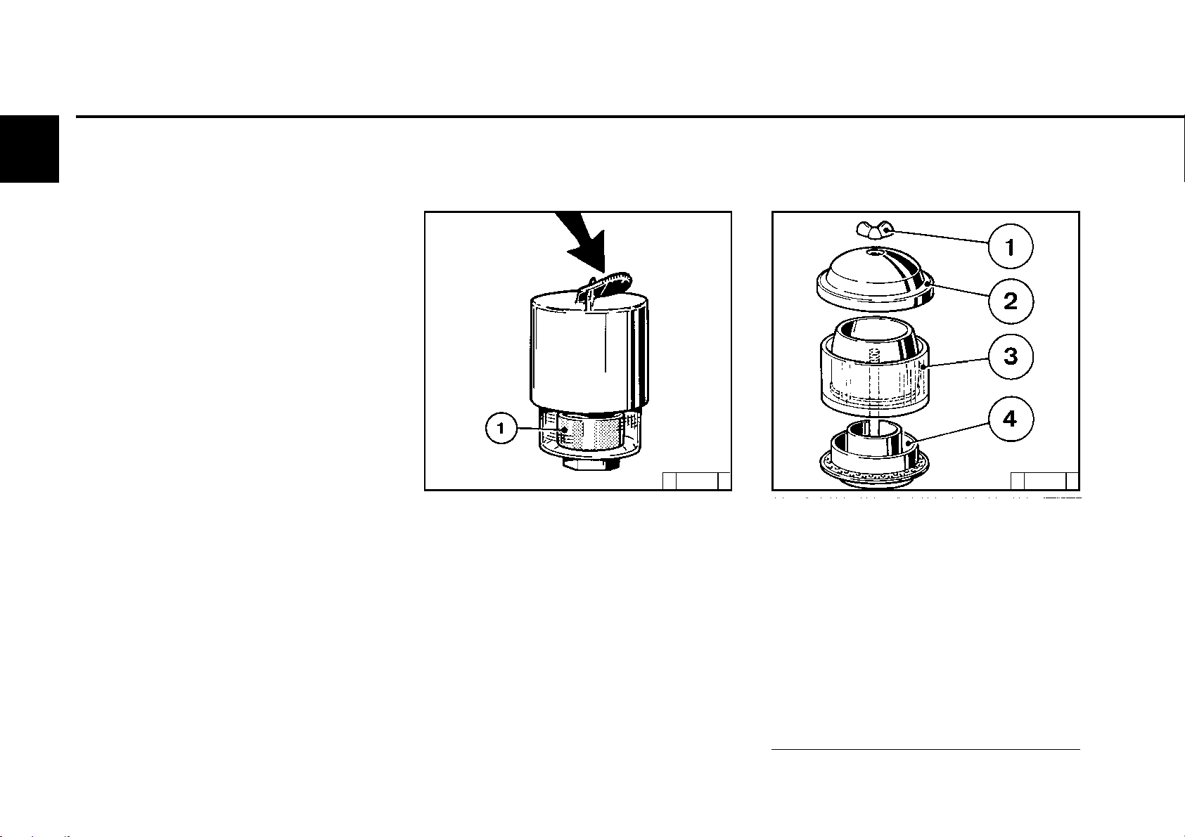
6.4.2 Emptying cyclone
pre-separator
© 25 886 0
● Loosen wing nut 1 and lift housing cover 2.
● Remove the dust container 3 from the base of
the cyclone 4 and empty. Clean foliage, straw
and the like from the cylone base.
● Place the dust container 3 on the base 4 and
tighten the housing cover 2 with wing nut 1.
© 2004
Never fill the dust container with oil, replace
damaged containers.
Page 57

6.4 Combustion air filter Care and maintenance work
6.4.3 Dry air filter
dust discharge valve
Filter cartridges
6©
© 25 888 1
● Empty the dust discharge valve 1 by squeezing
the discharge slot in the direction of the arrow.
● Clean the discharge slot occasionally.
● Remove any stuck on dust residues by
squeezing the upper area of the valve.
© 43 920 0
● Open clamping bracket A.
● Remove filter hood B and pull out filter cartridge
C.
● Clean filter cartridge, renew after a year at the
latest.
● Clean filter cartridge C.
Blast out from the inside out with dry
compressed air (max. 5 bar) (only beat out in
extreme cases or only wash according to
manufacturer’s specifications, not damaging
the cartridge).
● The seal of the filter cartridge C can be
damaged by frequent removal and installation.
Check filter cartridge C for damage to the filter
paper (shine light through) and check the seal.
Exchange if necessary.
● Renew the safety cartridge after five filter
maintenances, after two years at the latest
(never clean).
To do this:
- Loosen the hexagonal nut and pull out the
cartridge.
- Insert new cartridge and re-tighten with
hexagonal nut.
● Insert filter cartridge C, put on hood B and
fasten clamping bracket A.
Never clean filter cartridge C with
petrol or hot liquids!
© 2004
Page 58
6
Care and maintenance work 6.5 Belt drive
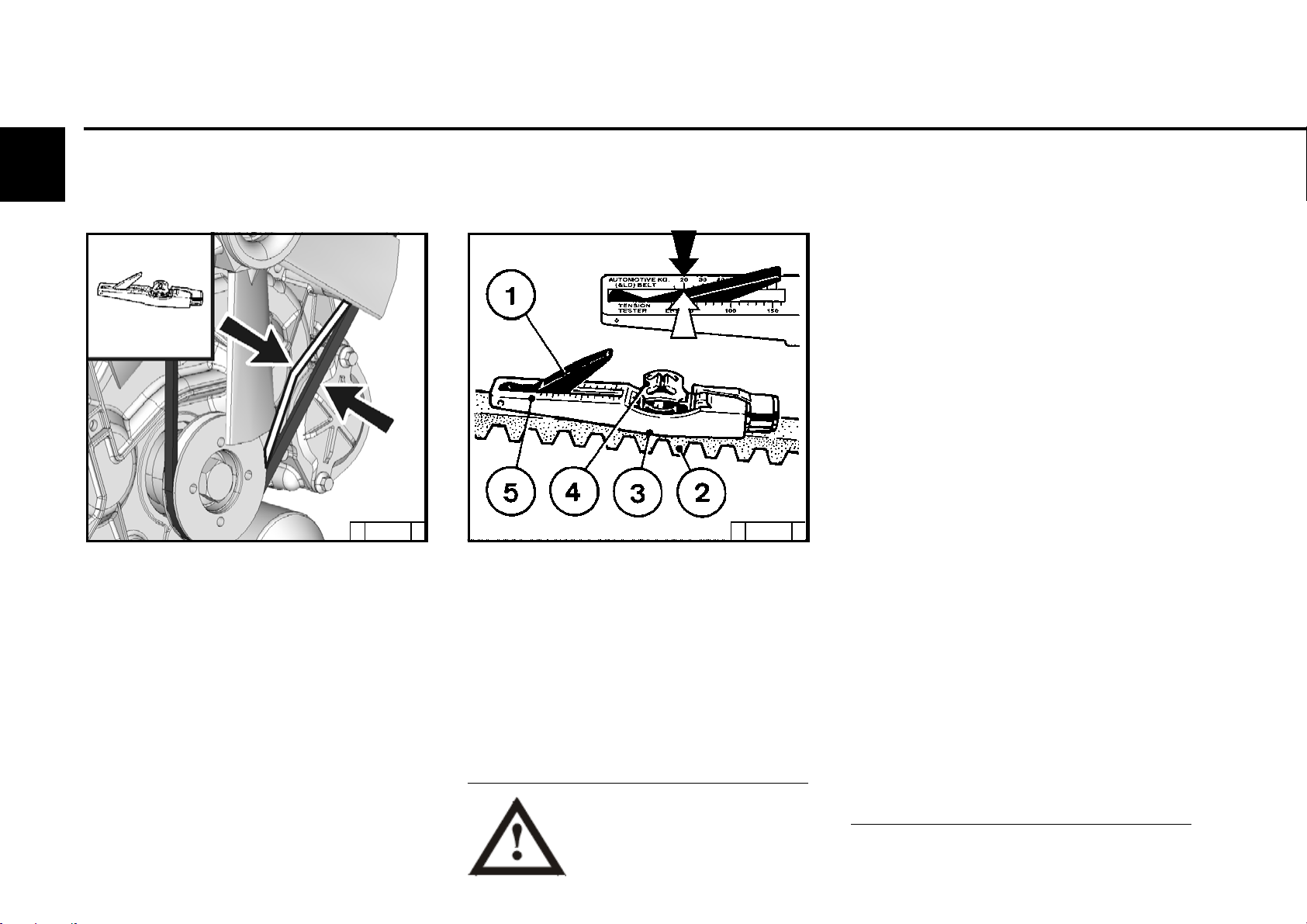
6.5.1 Checking V-belt6.5.1 Checking V-belt
© 43 875 0
● Visual inspection of entire length of V-belt
for damages.
● Renew damaged V-belts.
● Check the belt tension of new V-belts
after 15 minutes running time.
● Use a V-belt tension measuring device
(see chap. 9.3) to check the V-belt tension.
- Lower indicator arm 1 into the measuring
device.
- Lay the guide 3 between two belt pulleys
on the V-belt 2. The stop should lie sideways.
- Press the button 4 at right angles to the
V-belt 2 steadily, until the spring is heard or
felt to unlock.
© 2004
© 26 261 0
- Carefully lift the measuring device, without
altering the position of the indicator arm 1.
- Read off the measured value on the
intersection (arrow), scale 5 and indicator 1.
For setting values see 9.1.
- If necessary, re-tighten and repeat measurement.
Only test / tighten / change
V-belts when the engine is not
running. If necessary, re-mount
V-belt guard.
Check the belt tension of new V-belts after 15
minutes running time.
Page 59
6.5 Belt drive Care and maintenance work
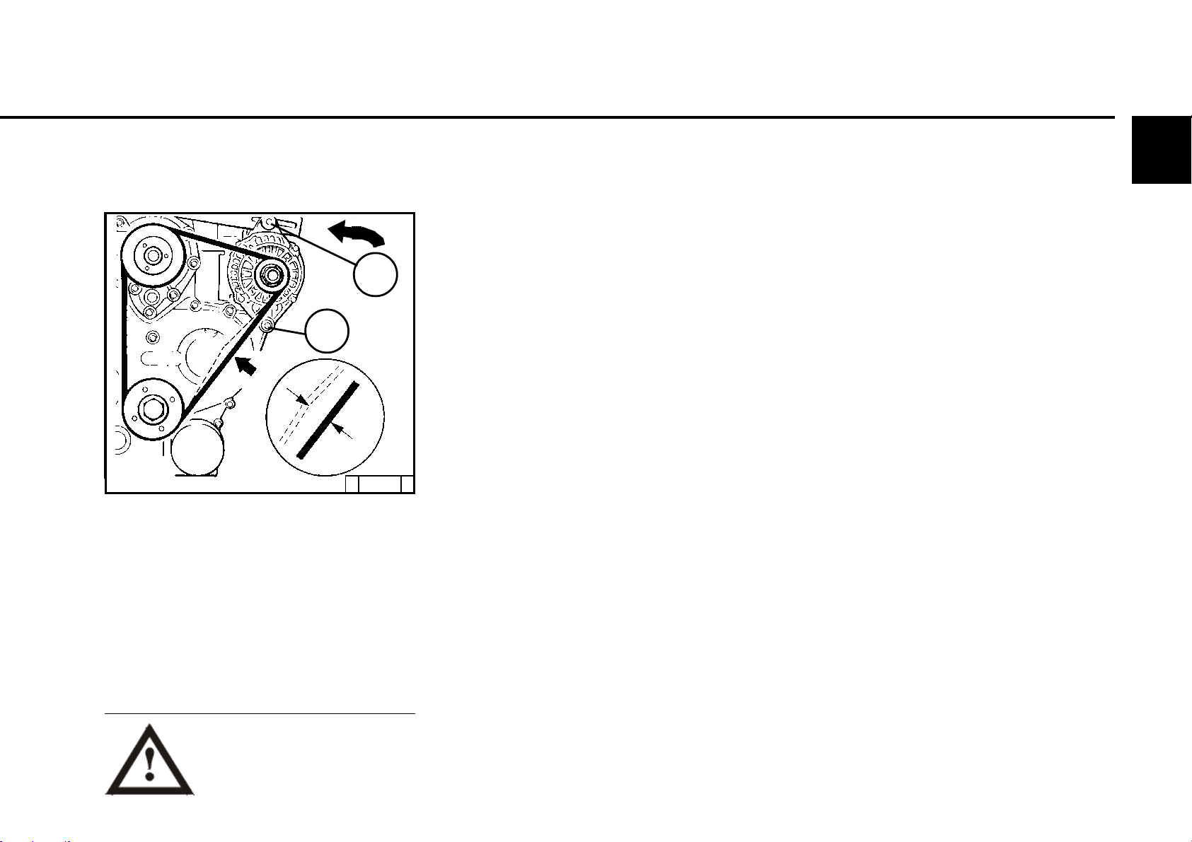
6.5.2 Tightening/changing
V-belts
1
2
6©
© 31 859 0
Tightening
● Loosen screw 1.
● Actuate the generator against the direction of
the arrow.
● Re-tighten screw 1.
● Check V-belt tension.
Only test / tighten / change
V-belts when the engine is not
running. If necessary, re-mount
V-belt guard.
Changing
● Loosen screws 1 and 2.
● Adjust the generator in the direction of the
arrow.
● Remove V-belt and put new belt on.
● Actuate the generator against the direction of
the arrow.
● Re-tighten screws 2 and 1.
● Check V-belt tension (see 6.5.1).
© 2004
Page 60
6
Care and maintenance work 6.6 Add-on components
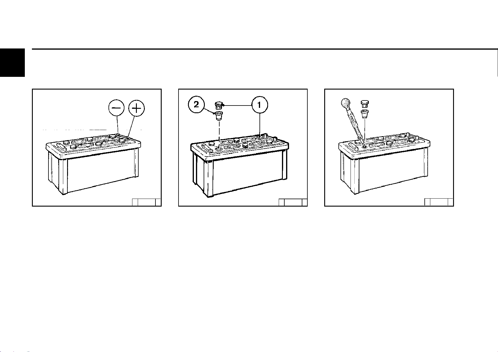
6.6.1 Battery
6.6.1.1Checking battery and cable
connections
6.6.1.2Checking the acid level 6.6.1.3 Checking acid density
© 25 895 0
● Keep the battery clean and dry.
● Loosen soiled connection terminals.
● Clean the battery poles (+ and -) and terminals,
and grease with an acid-free and acid-resistant
grease.
● Ensure that the terminal connections contact
well when assembling. Tighten the clamping
screws by hand.
© 2004
© 24 232 3
● Remove sealing cap 1.
● If a checking insert 2 is available:
the liquid level should reach to the bottom.
● Without checking insert:
the liquid level should reach 10-15 mm above
the upper edge of the plate.
● If necessary, re-fill with distilled water.
● Screw sealing cap back on.
© 25 896 0
● Measure the acid density of individual cells
with a standard acid testing device.
The measured values (see following table)
provide information on the charged level of the
battery.
The acid temperature when measuring should
be +20 °C if possible.
Page 61
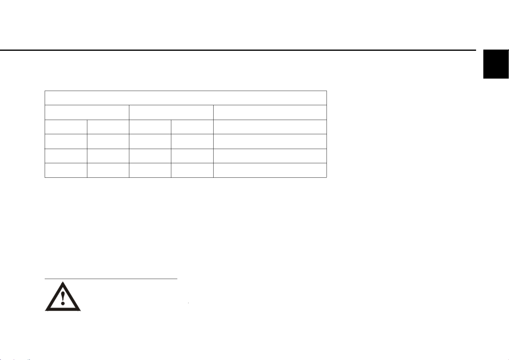
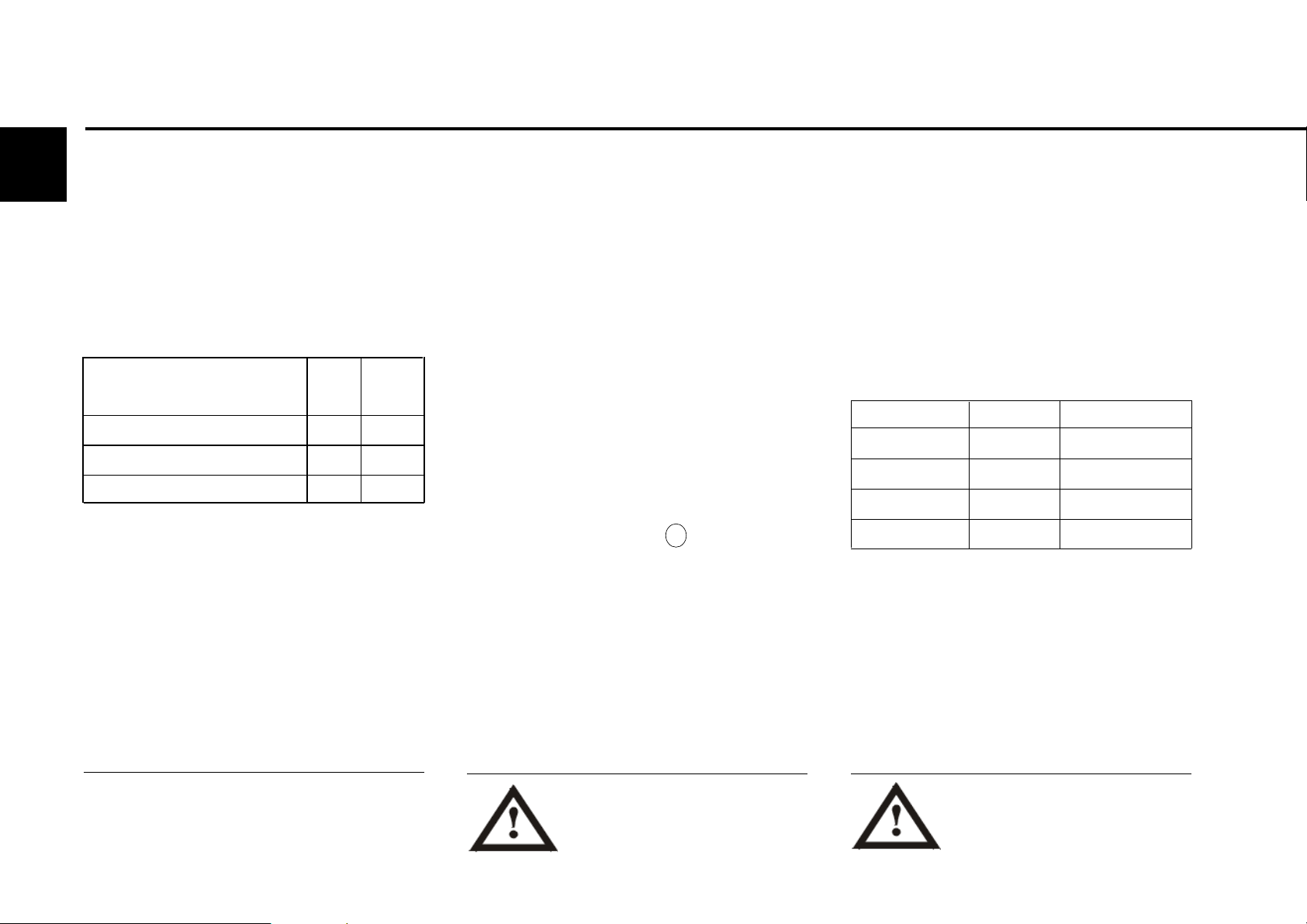
6.6 Add-on components Care and maintenance work
Acid density
6©
in [kg/ l]
Normal
1.28
1.20
1.12
* The data for acid density in °Bé (Baumé
degree) is out of date and rarely still in use.
Wear protective glasses!
Do not place any tools on the battery!
Tropics
1.23
1.12
1.08
The gases released by the battery
are explosive! Avoid sparks and
open fire in the vicinity of the
battery!
Do not allow acid to get on skin or
clothes!
in [°Bé (Baumé degree)*]
Normal
32
24
16
Tropics
27
16
11
Charge level
well charged
half charged, re-charge
discharged, charge immediately
© 2004
Page 62
Care and maintenance work 6.6 Add-on components
6
6.6.2 Three-phase current
generator
Notes on three-phase current system:
● Do not interrupt the connections between the
battery, generator and governor when the
engine is running.
● If, however, an engine must be started and
operated without battery, the connection
governor / generator is to be separated before
starting.
● Do not exchange battery connections.
● Replace defective charge warning light
immediately.
● Cover generator and governor when washing the engine.
● Under no circumstances may the voltage of a
three-phase current system be tested by
tapping against the earth cable.
● When carrying out electrical welding work,
clamp the earth terminal of the welding device
directly to the part to be clamped.
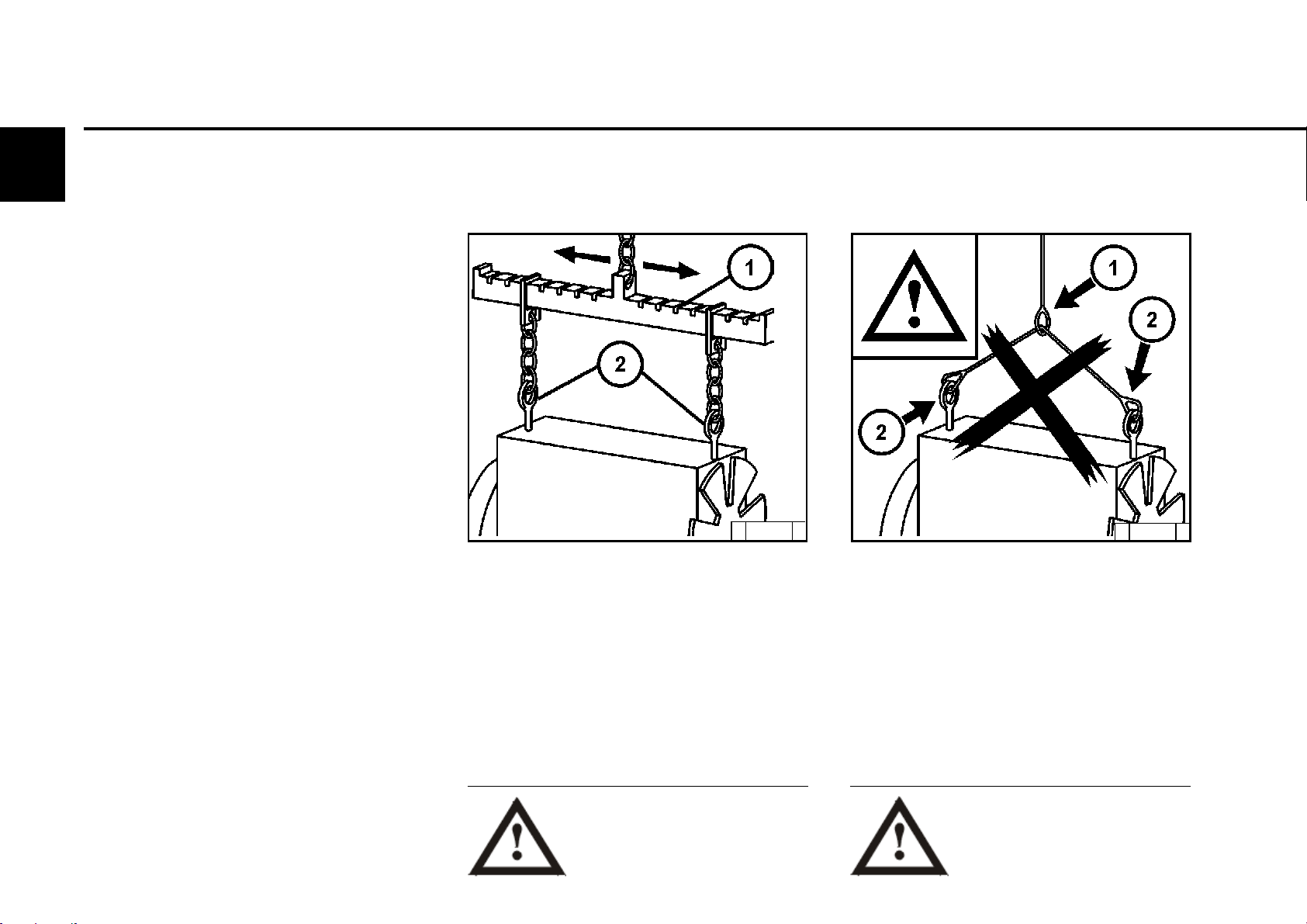
6.6.3 Transportation suspension
© 31 871 0
● Only use the correct suspension equipment 1
for engine transportation. Suspension
equipment must be adjustable for the engine
centre of gravity.
© 31 870 0
● Fastening devices cannot be fixed safely over
the centre of gravity (1).
● Fastening devices can slip, engine capsizes
(1).
● Short fastening device causes bending
moments in the suspension. This can damage
the suspension. (2)
© 2004
Only use correct suspension
equipment!
Engine can fall.
Danger to life!
Page 63

6.7 ENGINE CLEANING Care and maintenance work
6.7.1 Engine cleaning
Preparation
● Switch off engine
● Remove engine cover, cool air hood. Re-
assemble after cleaning and before trial run.
● Cover electrical / electronic components and
connections (e.g. generator, starter, governor,
lifting magnet).
With compressed air
● Blast out engine paying particular attention to
cooler and cooling fins (blast out beginning
from the exhaust side).
Remove any dirt blown inside.
With cold cleaner
● Spray the engine with standard cold cleaner
and leave to work for approx. 10 minutes.
● Spray the engine clean with an acute water jet,
repeat process if necessary.
● Warm up the engine so that the water residues
evaporate.
With a high pressure device
● Clean engine with steam jet (max. spray
pressure 60 bar, max. steam temperature
90 °C).
● Warm up the engine so that the water residues
evaporate.
6©
Only carry out cleaning work on
the engine when it is not running!
© 2004
Page 64

6
Care and maintenance work 6.7 Engine cleaning
© 2004
Page 65

7.1 Fault table
Faults, causes and remedies
7
© 2004
Page 66

7
Faults, causes and remedies 7.1 Fault table
z Faults can often be put down to the engine
not being operated correctly or not being
maintained.
z For every fault, check whether all operating
and maintenance instructions were
observed.
z A corresponding fault table can be found
overleaf.
z If you cannot recognise the cause of a fault
or cannot remedy a fault yourself please
contact your DEUTZ AG
© 2004
Page 67
7.1 Fault table Faults, causes and remedies
Faults Measures
Engine doesn’t start up, or starts up with difficulty Check P
Engines starts up, but runs irregularly or misfires Set E
Engine gets too hot. Temperature warning system is activated Change W
Engine lacks power Clean R
Engine doesn’t work on all cylinders Fill up A
Engine has no, or too little, oil pressure Lower S
Engine oil consumption is too high
Engine smoulders - blue
- white
- black
Causes
z
zz
zz
zz zz
zzz
zz
zz z z
zz z
zz z
zz
z
z
z
z
Not declutched (if possible)
Starting limit temperature not reached
Oil level too low
Oil level too high
Engine is tilted too far
Incorrect SAE class of engine lube oil and oil quality
Fuel quality does not comply with instruction manual
Air filter soiled / turbocharger defective
Air filter maintenance switch / display defective
Charge air line leaking
Fan defective / V-belt torn or loose
Cool air heating / heat short circuit
Resistance in cooling system is too high / flow volume too low
Battery defective or not charged
Section
Operation
Operating
substance
Combustion air
Cooling system
Electrics
P
P
A
P
S
W
W
P / W
P / W
P
P / W
P
P
P / A
7
© 2004
Page 68
7
Faults, causes and remedies 7.1 Fault table
Faults Measures
Engine doesn’t start up, or starts up with difficulty Check P
Engines starts up, but runs irregularly or misfires Set E
Engine gets too hot. Temperature warning system is activated Change W
Engine lacks power Clean R
Engine doesn’t work on all cylinders Fill up A
Engine has no, or too little, oil pressure Lower S
Engine oil consumption is too high
Engine smoulders - blue
- white
- black
z
z
zzz
zzzzz zz
Causes
Cable connections in starter circuit are loose or oxidised
Starter defective or pinion doesn’t mesh
Injection line leaking
Injection valve defective
Section
Electrics
Engine
P
P
P
P / W
© 2004
Page 69

Engine corrosion protection
8.1 Corrosion protection
8
Page 70

Engine corrosion protection
8.1 Corrosion protection
8
If the engine should be shut down for a long
period of time, corrosion protection will be
necessary in order to prevent rust formation.
The measures described here apply for a
shutdown period of up to 6 months.
Before the engine is commissioned again the
corrosion protection should be removed.
z Corrosion protection oils according to
specification:
MIL-L-21260B
TL 9150-037/2
Nato Code C 640 / 642
z Corrosion protection agent only for
exterior corrosion protection according
to specification:
Nato Code C 632
z Recommended cleaning agent for
removal of corrosion protection:
Petroleum benzine
(hazard class A3)
8.1.1 Protecting engine from
corrosion
z Clean engine with high-pressure
appliance (with cold cleaner if
absolutely necessary).
z Warm up the engine and switch off.
z Drain off engine oil, see chapter 6.1.2
and pour in corrosion protection oil.
z Clean oil discharge filter if necessary,
see chapter 6.4.3, and pour in corrosion
protection oil.
z Drain fuel from tank.
z Make fuel mixture from 90 % diesel fuel
and 10 % corrosion protection oil and fill
up tank.
z Leave the engine running for approx. 10
minutes.
z Switch off engine.
z Turn the engine several times by hand to
apply corrosion protection to the
cylinders and combustion chamber.
z Remove V-belt, pack up and store.
z Spray the grooves of the V-belt pulley
with corrosion protection agent.
z Seal intake and exhaust openings.
8.1.2 Removing engine corrosion
protection
z Remove corrosion protection agent from
grooves of V-belt pulley.
z Assemble V-belt. If necessary, re-
tighten after a short operating time, see
6.5.
z Remove seals from intake and exhaust
openings.
z Start up the engine.
Page 71

9.1 Engine and setting data
9.2 Screw tightening torques
Technical data
9
Page 72

Technical data 9.1 Engine and setting data
9
Engine type
Number of cylinders ----------------------------------------------------------------Cylinder arrangement ---------------------------------------------------------------Bore ------------------------------------------------------------------------------------ [mm]
Stroke ---------------------------------------------------------------------------------- [mm]
Total displacement -------------------------------------------------------------------- [cm
Compression ratio -------------------------------------------------------------------- [ε]
Working principle ---------------------------------------------------------------------
Combustion process----------------------------------------------------------------Direction of rotation ------------------------------------------------------------------Weight without cooling system (with starter, with generator) ----------------- ca [kg]
Engine power (at rpm) --------------------------------------------------------------- [kW]
Speed (example) --------------------------------------------------------------------- [rpm]
Lubrication / oil SAE -----------------------------------------------------------------Maximum oil temperature in oil tray ----------------------------------------------- [°C]
Minimum oil pressure in warm engine, oil temp. 110°C/ 230°F at:
max. 3000 rpm ------------------------------------------------------------------- [kPa/bar]
Engine with thermostat:
Oil change volume without external cooler / without filter approx. ------------ [ltr.]
Oil change volume without external cooler +
filter change (standard 0.5 ltr.) approx. ------------------------------------------- [ltr.]
Valve clearance:
Hydraulic tappet: Setting valve clearance is not necessary ---------
Start of pumping ----------------------------------------------------------- [°KW before TDC]
Engine ignition sequence ------------------------------------------------------------
V-belt tension: pre-tighten/re-tighten
(after the engine has been driven under load for 15 minutes): ---------------- [N]
3
]
------ D 2008 L03 -------------------------------- D 2008 L04 ------------
------------ 3 -------------------------------------------- 4 ------------------
------------------------------------ In-line -------------------------------------
-------------------------------------- 76 ---------------------------------------
-------------------------------------- 86 ---------------------------------------
---------- 1170 ---------------------------------------- 1560 ----------------
------------------------------------- 23.5 --------------------------------------
------------------------ Four-stroke diesel engine -------------------------
------------- Naturally aspirated engine with direct injection ------------
-------------------------- Left seen on fly wheel --------------------------
----------- 155 ------------------------------------------ 189 -----------------
------------------------------------- 3000 -------------------------------------
-------------------------- Forced feed lubrication / 20 W 20 -------------
--------------------------------------130 --------------------------------------
-------- 480 / 4.8 ------------------------------------- 400 / 4 ---------------
----------- 4.8 ------------------------------------------ 6.9 -----------------
----------- 5.3 ------------------------------------------ 7.4 -----------------
.1)
---------------------------------------
-------- 1 - 2 - 3 ----------------------------------- 1 - 3 - 4 - 2 ------------
------------------------------- 450 / 350 ±20 --------------------------------
. ---------------------------------------
1)
Engine power, speed and start of pumping, among other things, are stamped on the engine company plate, see also 2.1.
2)
Approx. value can vary depending on oil tray or cooler version (external cooling system). The upper oil dipstick marking is always decisive.
Page 73

Technical data 9.1 Engine and setting data
Engine type ---------------------------------------------------------------------------Number of cylinders ----------------------------------------------------------------Cylinder arrangement ---------------------------------------------------------------Bore ------------------------------------------------------------------------------------ [mm]
Stroke ---------------------------------------------------------------------------------- [mm]
Total displacement -------------------------------------------------------------------- [cm
3
]
Compression ratio -------------------------------------------------------------------- [ε]
Working principle ---------------------------------------------------------------------
Combustion process-----------------------------------------------------------------
------------------------------------------------------------------------------------------
Direction of rotation ------------------------------------------------------------------Weight without cooling system (with starter, with generator) ----------------- ca [kg]
Engine power (at rpm) --------------------------------------------------------------- [kW]
Speed (example) --------------------------------------------------------------------- [rpm]
Lubrication / oil SAE -----------------------------------------------------------------Maximum oil temperature in oil tray ----------------------------------------------- [°C]
Minimum oil pressure in warm engine, oil temp. 110°C/ 230°F at:
max. 3000 rpm ------------------------------------------------------------------- [kPa/bar]
Oil change volume without filter approx. ------------------------------------------ [ltr.]
Oil change volume with filter change (standard 0.5 ltr.) approx. -------------- [ltr.]
Valve clearance:
Hydraulic tappet: Setting valve clearance is not necessary ---------
-------- Start of pumping ------------------------------------------------- [°KW before TDC]
Engine ignition sequence ----------------------------------------------------------V-belt tension: pre-tighten/re-tighten
(after the engine has been driven under load for 15 minutes): ---------------- [N]
- D 2009 L03 ---------------- D 2009 L04 --------------- TD 2009 L04 ----
------- 3 ----------------------------- 4 ---------------------------- 4 -----------
------------------------------------ In-line -----------------------------------------
-------------------------------------- 90 -------------------------------------------
-------------------------------------- 90 -------------------------------------------
----- 1718 ------------------------ 2289 ------------------------ 2289 ---------
----- 19.6 -------------------------- 18 --------------------------- 18 -----------
------------------------ Four-stroke diesel engine -----------------------------
--Naturally aspirated ---- Naturally aspirated ----------- with charging ----
---- engine ---------------------- engine ----------------------------------------
----------------------------- and direct injection ---------------------------------
-------------------------- Left seen on fly wheel ------------------------------
----- 180 -------------------------- 205 -------------------------- 220 ----------
--------------------------------------- 1) -------------------------------------------
--------------------------------- max. 3000 --------------------------------------
-------------------- Forced feed lubrication/ 20 W 20 -------------------------
--------------------------------------130 ------------------------------------------
-- 200 / 2
---- 4.9
3)
. -------------------- 200 /2 3). ------------------- 220 /2,2 3). ------
2)
. ------------------------ 6.52). ------------------------ 6.52). ---------
------ 5.8--------------------------- 7.5 -------------------------- 7.5 ----------
------------------------------------------------------------------- 1) -------------------------------------------
---- 1-2-3 -------------------- 1 - 3 - 4 - 2 ------------------- 1-3-4-2--------
------------------------------- 450 / 350 ±20 ------------------------------------
9
1)
Engine power, speed and start of pumping, among other things, are stamped on the engine company plate, see also 2.1.
2)
Approx. value can vary depending on oil tray or cooler version (external cooling system). The upper oil dipstick marking is always decisive.
3)
Date for engines without engine oil heating.
Page 74

9
Technical data
Installation Pre-tightening Re-tightening Total Comments
[Nm] 1st step 2nd step 3rd step 4th step Nm
Cylinder head cover 27
Rocker arm setting screw – – – – – 27 ± 2
Intake elbow – – – – – 27 M8x125
Air intake pipe – – – – – 27
Exhaust manifold – – – – – 27
Oil drain screw sheet metal oil tray – – – – – 32 M14x1.50
Injection valve fastening – – – – – 28
Lube oil filter cartridge – – – – – 27
9.2 Screw tightening torques
Starter – ––––41
Page 75

Notes
en
Warnings to Place on Equipment
CALIFORNIA
Proposition 65 Warning
Diesel engine exhaust and some of its
constituents are known to the State of
California to cause cancer, birth
defects, and other reproductive harm.
Warning in the Manual
CALIFORNIA
Proposition 65 Warning
Diesel engine exhaust and some of its
constituents are known to the State of
California to cause cancer, birth
defects, and other reproductive harm.
or
CALIFORNIA
Proposition 65 Warning
Diesel engine exhaust and some of its constituents are known
to the State of California to cause cancer, birth defects, and
other reproductive harm.
Page 76

C
ALIFORNIA
P
ROPOSITION
65 I
NFORMATION
Notes
en
TOC
TO CUSTOMERS SELLING DIESEL ENGINE EQUIPMENT INTO OR
Proposition 65, a California law, requires warnings on products which expose individuals in California to chemicals listed under that law,
including certain chemicals in diesel engine exhaust.
Obligations of Manufactures of Diesel-Powered Off-Road Equipment. The California Superior Court has approved either of the following
two methods of compliance with Proposition 65 requirements by manufactures of off-road equipment containing diesel engines. (The court
order containing these provisions is attached.)
1.
On-Equipment Warning. Place the warning pictured in attachment 1 on all equipment shipped by you into or for sale in California after
January 1, 1996. The warning must be in a location where it is easily visible to the operator of the equipment when (s)he is operating the
equipment. The warning must be secured to the equipment. If warnings or operating instructions are provided through a digital display,
you may usee that method of providing warning.
Operator Manual Warning. When the operator manual is next revised or by December 31, 1995 whichever is earlier, place the warning
2.
in attachment 2 in the operator manual. The warning may be either printed in the manual or on a sticker.
The warning must appear in one of the following locations:
●
Inside The front cover
●
Inside the back cover
●
Outside the front cover
●
Outside the back cover
●
As the first page of text
ALIFORNIA CUSTOMERS AND
C
FOR USE IN
ALIFORNIA.
en
Under either alternative, the warning must appear in the same size, print and format as the attachment selected or be of an equally conspicuous
size and format. If the warning is provided in an on-screen display, the warning must contain the language in the attachment and must be
provided at the time of or in connection with ignition in the same manner as other safety warnings electronically communicated on screen.
Obligation of Resellers of Diesel Engines. This letter must accompany any loose diesel engine sold in California.
Should you have any questions, please call Deutz Corporation Product Support Department.
Page 77

Service
de
For many years DEUTZ has stood for pioneering
development in engine construction. As an independent engine manufacturer we offer a
complete palette of diesel and gas engines
worldwide. Our products are perfectly tailored
to meet the requirements of our customers.
More than 1.4 million DEUTZ engines reliably
perform their service all over the world. We want
to preserve the operational readiness of our
engines and with it the satisfaction of our
customers. Therefore we are represented
worldwide by a network of competent partners,
the concentration of whom corresponds to the
regional distribution of our engines.
Thus, DEUTZ is not just a name for innovative
engines. But also for a complete service package
for every aspect of engines, and a service that
you can rely on.
You can find a complete overview of DEUTZ
partners in your area, their product competencies and their services on the DEUTZ website
(see below).
Also if there is no direct product competency
specified, your DEUTZ partner will be able to help
you further with professional advice.
10
Your DEUTZ AG
Deutz-Mülheimer Str. 147-149
D-51063 Cologne
Telephone: 0049-221-822-0
Fax: 0049-221-822-3523
Telex: 8812-0 khd d
http://www.deutz.de
Page 78

Impressum:
DEUTZ AG
Service Informatin Systems
Deutz-Mülheimer Straße 147-149
D - 51057 Köln
Telefon: + 49 (0) 221 - 822 - 0
Fax: + 49 (0) 221 - 822 - 5358
Internet: www.deutz.de
E-mail: info@deutz.de
Printed in Germany
All rights reserved
1st Edition ,© 03/05
The engine company
Order.-Nr. 0312 1419
 Loading...