


 Loading...
AVR-X500
AV SURROUND RECEIVER
Owner’s Manual
Information instructions Advanced instructions Basic
nSAFETY PRECAUTIONS
CAUTION
RISK OF ELECTRIC SHOCK
DO NOT OPEN
CAUTION:
TO REDUCE THE RISK OF ELECTRIC SHOCK, DO NOT REMOVE COVER (OR BACK). NO USER-SERVICEABLE PARTS INSIDE. REFER SERVICING TO QUALIFIED SERVICE PERSONNEL.
The lightning flash with arrowhead symbol, within an equilateral triangle, is intended to alert the user to the presence of uninsulated “dangerous voltage” within the product’s enclosure that may be of sufficient magnitude to constitute a risk of electric shock to persons.
The exclamation point within an equilateral triangle is intended to alert the user to the presence of important operating and maintenance (servicing) instructions in the literature
accompanying the appliance.
WARNING:
TO REDUCE THE RISK OF FIRE OR ELECTRIC SHOCK, DO NOT EXPOSE THIS APPLIANCE TO RAIN OR MOISTURE.
|
|
|
CAUTION: |
|
|
|
HOT SURFACE. DO NOT TOUCH. |
|
|
|
The top surface over the internal heat sink may become hot |
|
Hot |
||
|
when operating this product continuously. |
||
surface |
Do not touch hot areas, especially around the “Hot surface |
||
mark |
mark” and the top panel. |
||
IMPORTANT SAFETY
INSTRUCTIONS
1.Read these instructions.
2.Keep these instructions.
3.Heed all warnings.
4.Follow all instructions.
5.Do not use this apparatus near water.
6.Clean only with dry cloth.
7.Do not block any ventilation openings.
Install in accordance with the manufacturer’s instructions.
8.Do not install near any heat sources such as radiators, heat registers, stoves, or other apparatus (including amplifiers) that produce heat.
9.Protect the power cord from being walked on or pinched particularly at plugs, convenience receptacles, and the point where they exit from the apparatus.
10.Only use attachments/accessories specified by the manufacturer.
11.Use only with the cart, stand, tripod, bracket, or table
specified by the manufacturer, or sold with the apparatus. When a cart is used, use caution when moving the cart/ apparatus combination to avoid injury from tip-over.
12. Unplug this apparatus during lightning storms or when unused for long periods of time.
13.Refer all servicing to qualified service personnel.
Servicing is required when the apparatus has been damaged in any way, such as power-supply cord or plug is damaged, liquid has been spilled or objects have fallen into the apparatus, the apparatus has been exposed to rain or moisture, does not operate normally, or has been dropped.
14.Batteries shall not be exposed to excessive heat such as sunshine, fire or the like.
CAUTION:
To completely disconnect this product from the mains, disconnect the plug from the wall socket outlet.
The mains plug is used to completely interrupt the power supply to the unit and must be within easy access by the user.
•DECLARATION OF CONFORMITY
Our products following the provisions of EC/EU directives, that as follows; LV: 2006/95/EC
EMC: 2004/108/EC RoHS: 2011/65/EU
ErP: EC regulation 1275/2008 and its frame work directive 2009/125/EC
Denon EUROPE
Division of D&M Germany GmbH
An der Kleinbahn 18, Nettetal,
D-41334 Germany
A NOTE ABOUT RECYCLING:
This product’s packaging materials are recyclable and can be reused. Please dispose of any materials in accordance with the local recycling regulations.
When discarding the unit, comply with local rules or regulations.
Batteries should never be thrown away or incinerated but disposed of in accordance with the local regulations concerning battery disposal.
This product and the supplied accessories, excluding the batteries, constitute the applicable product according to the WEEE directive.
Information instructions Advanced instructions Basic
I
nNOTES ON USE
WARNINGS
•Avoid high temperatures.
Allow for sufficient heat dispersion when installed in a rack.
•Handle the power cord carefully.
Hold the plug when unplugging the cord.
•Keep the unit free from moisture, water, and dust.
•Unplug the power cord when not using the unit for long periods of time.
•Do not obstruct the ventilation holes.
•Do not let foreign objects into the unit.
•Do not let insecticides, benzene, and thinner come in contact with the unit.
•Never disassemble or modify the unit in any way.
•Ventilation should not be impeded by covering the ventilation openings with items, such as newspapers, tablecloths or curtains.
•Naked flame sources such as lighted candles should not be placed on the unit.
•Observe and follow local regulations regarding battery disposal.
•Do not expose the unit to dripping or splashing fluids.
•Do not place objects filled with liquids, such as vases, on the unit.
•Do not handle the mains cord with wet hands.
•When the switch is in the OFF (STANDBY) position, the equipment is not completely switched off from MAINS.
•The equipment shall be installed near the power supply so that the power supply is easily accessible.
•Do not keep the battery in a place exposed to direct sunlight or in places with extremely high temperatures, such as near a heater.
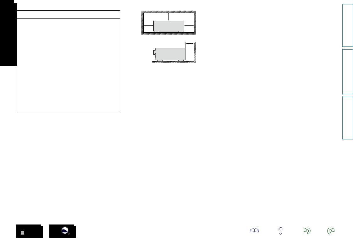
n CAUTIONS ON INSTALLATION
z
z |
z |
z
Wall
zz For proper heat dispersal, do not install this unit in a confined space, such as a bookcase or similar enclosure.
•More than 0.3 m is recommended.
II
Information instructions Advanced instructions Basic
Getting started
Thank you for purchasing this Denon product. To ensure proper operation, please read this owner’s manual carefully before using the product. After reading this manual, be sure to keep it for future reference.
Contents
Getting started···············································································1
Accessories···················································································1
Features························································································2 Cautions on handling·····································································2
Basic instructions···································································3
Connections···················································································4
Important information····································································4 Connecting HDMI devices····························································5 Connecting other devices······························································9 Connecting the power cord·························································14 Playback (Basic operation)··························································15
Important information··································································15 Playing a Blu-ray Disc player/DVD player·····································16 Playing a portable player······························································16 Tuning in radio stations·······························································17
Selecting a listening mode (Surround mode)···························21
Standard playback·······································································22 Multi-channel stereo playback·····················································23 Virtual playback············································································23 Stereo playback···········································································23 Direct playback············································································23
Advanced instructions ·····················································24
Installation/connection/setup of speakers (Advanced)···········25
Speaker installation·····································································25 Speaker connection·····································································26 Playback (Advanced operation)··················································29
Adjusting the volume of the speakers·········································29 Sleep timer function····································································30 Quick select function···································································30 Various memory functions··························································30 How to make detailed settings··················································31
Menu map···················································································31 Examples of menu and front display···········································32 Inputs··························································································33 Speakers······················································································36 General························································································39 Adjusting the sound field effects·················································41 Information··················································································45
Other settings··············································································45
Switching between PAL and NTSC signal formats·····················45
Information·············································································46
Part names and functions···························································47
Front panel··················································································47 Display·························································································48 Rear panel···················································································49 Remote control unit·····································································50 Other information········································································52
Trademark information································································52 Surround······················································································53 Relationship between video signals and monitor output············55 Explanation of terms···································································56 Troubleshooting··········································································58
Resetting the microprocessor·····················································60 Specifications···············································································60
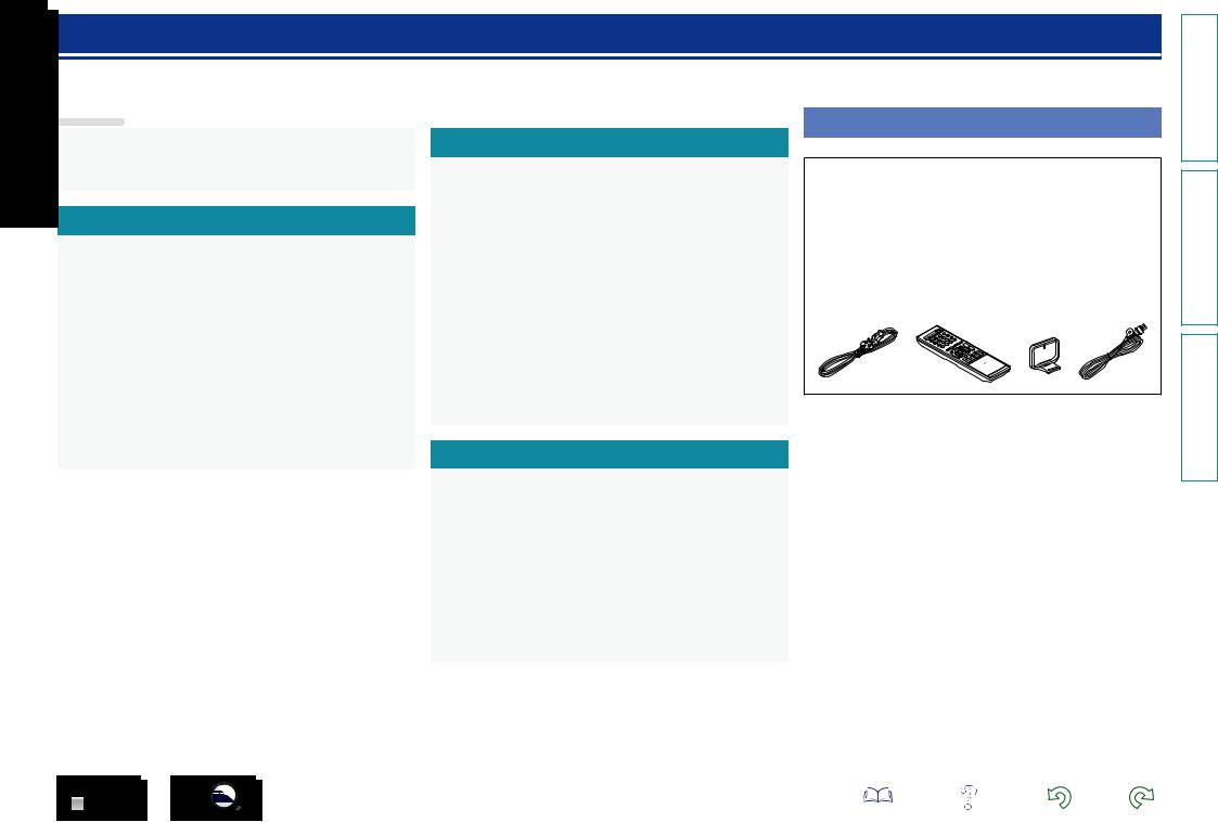
Accessories
Check that the following parts are supplied with the product.
q Getting Started......................................................................... |
|
|
1 |
w CD-ROM (Owner’s Manual)..................................................... |
|
1 |
|
e Safety Instructions................................................................... |
|
|
1 |
r Power cord............................................................................... |
|
|
1 |
t Remote control unit (RC-1180)................................................ |
|
1 |
|
y R03/AAA batteries................................................................... |
|
|
2 |
u AM loop antenna...................................................................... |
|
|
1 |
i FM indoor antenna................................................................... |
|
|
1 |
o Cable label................................................................................ |
|
|
1 |
r |
t |
u |
i |
Information instructions Advanced instructions Basic
1
Features
With discrete circuit technology, the power amplifier provides identical quality for all 5 channels (110 Watts x 5 channels)
For optimum realism and stunning dynamic range, the power amplifier section features discrete power devices (not integrated circuitry).
By using high current, high power discrete power devices, the amplifier is able to easily drive high quality speakers.
HDMI connections enable quick connection to various digital AV devices (4 inputs, 1 output) (vpage 5)
The unit is equipped with 4 HDMI input connectors for connecting devices with HDMI connectors, such as a Blu-ray Disc player, game console, HD digital camcorder, etc.
Supports HDMI (3D, Deep Color and “x.v.Color”) (vpage 8)
Advanced HDMI features are supported, including 3D passthrough, Deep Color and “x.v.Color”.
High definition audio support
The unit is equipped with a decoder which supports high-quality digital audio format for Blu-ray Disc players such as Dolby TrueHD, DTS-HD Master Audio, etc.
Features an PORTABLE input jack on the front panel for connecting portable audio player
(vpage 13)
Compressed Audio Restorer is Denon technology that restores compressed music sources to their original pre-compressed quality to give you a lively sonic ambience with greater detail and depth.
GUI overlay on HD source
You can easily make settings for your home theatre system while viewing menus on the TV screen. These menu displays can also be output to the monitor over HDMI.
Easy to use, screen display
Simple settings are enabled with the setting menus displayed on the TV screen. When you control the sound volume, the volume level is displayed on the screen, and when you switch the input source, the name of the input source is displayed.
Cautions on handling
•Before turning the power on
Check once again that all connections are correct and that there are no problems with the connection cables.
•Power is supplied to some of the circuitry even when the unit is set to the standby mode. When going on vacation or leaving home for long periods of time, be sure to unplug the power cord from the power outlet.
•About condensation
If there is a major difference in temperature between the inside of the unit and the surroundings, condensation (dew) may form on the operating parts inside the unit, causing the unit not to operate properly.
If this happens, let the unit sit for an hour or two with the power turned off and wait until there is little difference in temperature before using the unit.
•Cautions on using mobile phones
Using a mobile phone near this unit may result in noise. If that occurs, move the mobile phone away from this unit when it is in use.
•Moving the unit
Turn off the power and unplug the power cord from the power outlet. Next, disconnect the connection cables to other system units before moving the unit.
•About care
•Wipe the cabinet and control panel clean with a soft cloth.
•Follow the instructions when using a chemical cleaner.
•Benzene, paint thinner or other organic solvents as well as insecticide may cause material changes and discoloration if brought into contact with the unit, and should therefore not be used.
Information instructions Advanced instructions Basic
2
Basic instructions
Basic instructions
Here we explain the connections and basic operation methods for this unit.
F Connections vpage 4
F Playback (Basic operation) vpage 15
F Selecting a listening mode (Surround mode) vpage 21
For speaker connections, see page 26.
3
Information instructions Advanced instructions Basic
Connections
Important information
Make connections before using this unit.
To create a home theater that can play back higher quality video and audio by fully utilizing the capabilities of the unit and your video devices, connect the unit to each of your video devices with HDMI cables.
nnHDMI devices
vpage 6 |
vpage 7 |
vpage 7 |
vpage 7 |
vpage 7 |
|
If your video device does not support HDMI connections, use the following connection.
nnOther devices
vpage 10 |
vpage 11 |
vpage 12 |
vpage 12 |
vpage 13 |
vpage 13 |
|
PORTABLE |
|
This unit can change the source that is assigned to the DIGITAL AUDIO IN connectors.
You can change the source for connectors listed in Input connector setting within pages that describe connections for devices.
For details on assigning a source to connectors, see “Changing the source assigned to connectors” (vpage 9). For the setting method, see “Input Assign” (vpage 34).
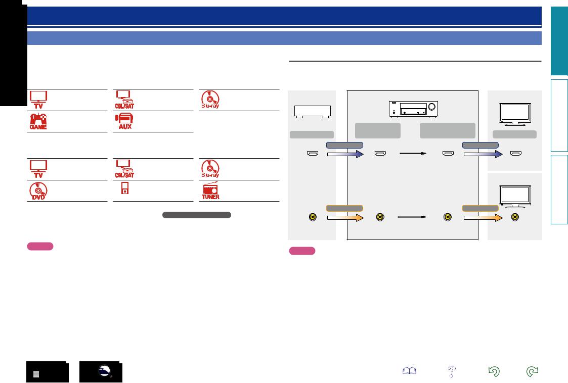
Relationship between video signals and monitor output
This unit is equipped with two types of video input connectors (HDMI and composite video) and two types of video output connectors (HDMI and composite video).
GFlow of video signalsH
Video device |
|
This unit |
HDMI-compatible TV |
|
|
||
|
|
|
|
|
Input |
Output |
|
Output |
(IN) |
(MONITOR OUT) |
Input |
|
HDMI signal |
HDMI signal |
|
HDMI connector |
HDMI connector |
HDMI connector |
HDMI connector |
|
|
|
HDMI-incompatible |
|
|
|
TV |
|
Video signal |
Video signal |
|
Video connector |
Video connector |
Video connector |
Video connector |
NOTE
•The menu screen is only displayed on TV connected to this unit via HDMI. If your TV is connected to this unit via other video output connectors, perform menu operations while seeing the display on this unit.
•When making connections, also refer to the operating instructions of the other devices being connected.
•Be sure to connect the left and right channels properly (left with left, right with right).
•Do not bundle power cords together with connection cables. Doing so can result in noise.
NOTE
•The menu screen is only displayed on TV connected to this unit via HDMI. If your TV is connected to this unit via other video output connectors, perform menu operations while seeing the display on this unit.
•HDMI signals cannot be converted into analog signals (vpage 55).
•Analog signals cannot be converted into HDMI signals (vpage 55).
Information instructions Advanced instructions Basic
4

Examples of screen display
|
|
|
|
•Setup Menu screen |
•Status display screen |
||
|
|
|
|
||||
|
|
|
|
|
|
|
When the input source is |
|
|
|
|
|
|
|
|
|
|
|
|
|
|
|
switched. |
|
|
|
|
|
Setup Menu |
|
|
|
|
|
|
|
|
Input Assign |
|
|
|
|
|
|
Inputs |
|
|
|
|
|
|
|
Speakers |
Source Level |
|
|
|
|
|
|
General |
Input Select |
|
|
|
|
|
|
|
Video Source |
|
|
|
|
|
|
|
|
|
|
|
|
|
|
|
|
|
|
|
[Auto] |
|
|
SOURCE:CBL/SAT |
ENTER Enter |
BACK Return |
MODE :MULTI CH STEREO |
Important information
When the volume is adjusted.
Master Volume |
29.0 |
||
|
|
|
|
|
|
|
|
Status display: The operating status appears briefly on the screen when the input source is switched or the volume is changed.
NOTE
•The menu screen is only displayed on TV connected to this unit via HDMI. If your TV is connected to this unit via other video output connectors, perform menu operations while seeing the display on this unit.
•If you operate the menu while playing back 3D video content or computer’s resolution (e.g. VGA), the playback video is replaced by the menu screen. The playback video is not displayed behind the menu screen.
•This unit does not show the status display while playing back 3D video content or computer’s resolution (e.g. VGA).
Connecting HDMI devices
You can connect up to five HDMI-compatible devices (4-inputs/1-output) to the this unit.
If the device connected to this unit is equipped with an HDMI connector, it is recommended to use HDMI connections. Connections with an HDMI cable offer the following benefits that can not be achieved with other connection methods.
•High quality playback by transmitting audio and video via digital signals
HDMI connections can transmit high definition video and high quality audio formats adopted by Bluray disc players (Dolby Digital Plus, Dolby TrueHD, DTS-HD, DTS-HD Master Audio).
HDMI connections also convey information required for playback between devices. This information is used for copyright protection and TV resolution recognition.
•Transmission of audio and video signals with a single HDMI cable
Previous connections required multiple audio and video cables, but HDMI connections require only a single HDMI cable to transmit audio and video signals. This allows wires in a home theater system, which tend to be complicated, to be more easily organized.
•Pass Through (vpage 40)
Outputs signals received from the HDMI input connector to the TV connected to the HDMI output connector even when the unit is in standby mode.
•This unit also supports 3D video playback and other functions related to video and audio (vpage 8).
•There is more than one version of the HDMI standard. The supported functions and the performance vary according to the version. This unit complies with the HDMI standard that supports the 3D playback functions. To enjoy these functions, the HDMI device connected to this unit also needs to use the same version of the standard. For the version of the HDMI standard on the device connected to this unit, see the device’s manual.
•Some TVs do not support audio input via HDMI connections. For details, see your TV’s manual.
•When “Pass Through” is set to other than “Off”, more power is consumed than in normal standby mode.
nn Connecting this unit to a TV via HDMI connections (vpage 6)
nn Connecting this unit to video devices via HDMI connections (vpage 7)
nn HDMI function (vpage 8)
nn Settings related to HDMI connections (vpage 8)
Information instructions Advanced instructions Basic
5
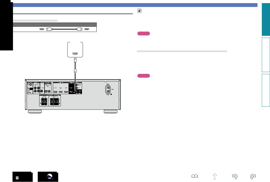
Connecting this unit to a TV via HDMI connections
Cables used for connections
Audio and video cable (sold separately)
HDMI cable
•This interface allows transfer of digital video signals and digital audio signals over a single HDMI cable.
TV
HDMI
IN
Connecting HDMI devices
•Video signals are not output if the input video signals do not match the display’s resolution. In this case, switch the Blu-ray Disc/DVD player’s resolution to a resolution with which the display is compatible.
•When this unit and monitor are connected with an HDMI cable, if the display or monitor is not compatible with HDMI audio signal playback, only the video signals are sent to the display or monitor. Make audio connections (vpage 10 “Connecting a TV”).
NOTE
•The audio signal from the HDMI output connector (sampling frequency, number of channels, etc.) may be limited by the HDMI audio specifications of the connected device regarding permissible inputs.
•Only an HDMI signal is output from the HDMI MONITOR OUT connector.
Connecting to a device equipped with a DVI-D connector
The DVI-D (Digital Visual Interface) method is also used for video transmission via digital signals. This is developed mainly for computers, and some displays such as projectors are equipped with this interface. To output HDMI video signals to a DVI-D video input compatible device, use an HDMI/DVI conversion cable or adapter.
The DVI-D connector can transmit high quality digital video signals, but copy guard and other issues may hinder normal operations for some device combinations.
NOTE
•No sound is output when connected to a device equipped with a DVI-D connector. Make audio connections as described in “Connecting a TV” (vpage 10).
•Signals cannot be output to DVI-D devices that do not support HDCP.
•Depending on the combination of devices, the video signals may not be output.
6
Information instructions Advanced instructions Basic
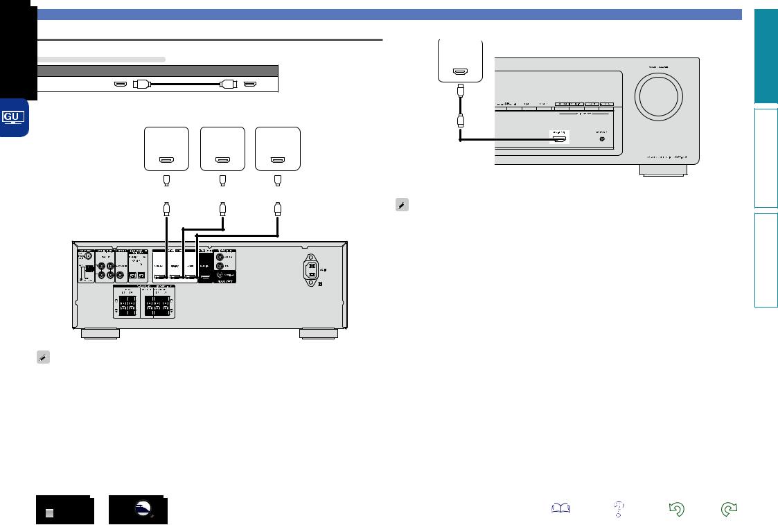
Connecting this unit to video devices via HDMI connections
Cables used for connections
Audio and video cable (sold separately)
HDMI cable
|
|
|
|
|
|
|
|
|
|
|
|
|
|
|
|
|
|
|
|
|
|
|
|
|
|
|
|
|
|
|
|
|
|
|
|
|
|
|
|
|
|
|
|
|
|
|
|
|
Blu-ray Disc |
|
|
|
|
|
|
||||
|
|
|
Set-top |
|
player / |
|
Game |
||||||||||||
|
|
|
box |
|
DVD player |
|
console |
||||||||||||
|
|
|
HDMI |
HDMI |
|
HDMI |
|||||||||||||
|
|
|
|
||||||||||||||||
|
|
|
OUT |
OUT |
|
OUT |
|||||||||||||
|
|
|
|
|
|
|
|
|
|
|
|
|
|
|
|
|
|
|
|
|
|
|
|
|
|
|
|
|
|
|
|
|
|
|
|
|
|
|
|
|
|
|
|
|
|
|
|
|
|
|
|
|
|
|
|
|
|
|
|
|
|
|
|
|
|
|
|
|
|
|
|
|
|
|
|
|
|
|
|
|
|
|
|
|
|
|
|
|
|
|
|
|
|
|
|
|
|
|
|
Connecting HDMI devices
Video camcorder
HDMI
OUT
GFront panelH
You can enjoy games by connecting a game machine via the AUX HDMI connector. In this case, select the input source to “AUX”.
GRear panelH
•When this unit is connected to other devices with HDMI cables, connect this unit and TV also with an HDMI cable.
•When connecting a device that supports Deep Color, please use a “High Speed HDMI cable” or “High Speed HDMI cable with Ethernet”.
Information instructions Advanced instructions Basic
7
Connecting HDMI devices
HDMI function |
|
Settings related to HDMI connections |
This unit supports the following HDMI functions: |
Set as necessary. For details, see the respective reference pages. |
|
nnAbout 3D function
This unit supports input and output of 3D (3 dimensional) video signals of HDMI.
To play back 3D video, you need a TV and player that provide support for the HDMI 3D function and a pair of 3D glasses.
NOTE
•When playing back 3D video, refer to the instructions provided in the manual of your playback device together with this manual.
•If you operate the menu while playing back 3D video content, the playback video is replaced by the menu screen. The playback video is not displayed behind the menu screen.
•This unit does not show the status display while playing back 3D video content.
•If 3D video with no 3D information is input, the menu screen and status display on this unit are displayed over the playback video.
•If 2D video is converted to 3D video on the television, the menu screen and status display on this unit are not displayed correctly. To view the menu screen and status display on this unit correctly, turn the television setting that converts 2D video to 3D video off.
nnHDMI (vpage 40)
Make settings for HDMI. |
|
|
•HDMI Audio Out |
•Pass Through |
•Pass Source |
NOTE
The audio signal input from the HDMI input connector can be output as an output signal from the HDMI output connector by setting the HDMI audio output destination to TV.
Audio signals input via the Analog/Optical input connectors cannot be output from the HDMI output connector.
nnDeep Color (vpage 56)
When a device supporting Deep Color is connected (such as an HD camcorder), use a cable compatible with “High Speed HDMI cable” or “High Speed HDMI cable with Ethernet”.
nn“x.v.Color”, sYCC601 color, Adobe RGB color, Adobe YCC601 color (vpage 56, 57)
nnHigh definition digital audio format
Copyright protection system
In order to play back digital video and audio such as BD-Video or DVD-Video via HDMI connection, both this unit and TV or the player need to support the copyright protection system known as HDCP (Highbandwidth Digital Content Protection System). HDCP is copyright protection technology comprised of data encryption and authentication of the connected AV devices. This unit supports HDCP.
•If a device that does not support HDCP is connected, video and audio are not output correctly. Read the owner’s manual of your television or player for more information.
8
Information instructions Advanced instructions Basic
Connecting other devices
For highest quality video and surround playback, it is recommended to use an HDMI cable to connect this unit to TV and other video devices (vpage 5 “Connecting HDMI devices”).
This section describes alternate connection methods when your device does not support HDMI connections.
Connection methods for various devices
vpage 10
vpage 12
vpage 13
PORTABLE
vpage 11
vpage 12
vpage 13
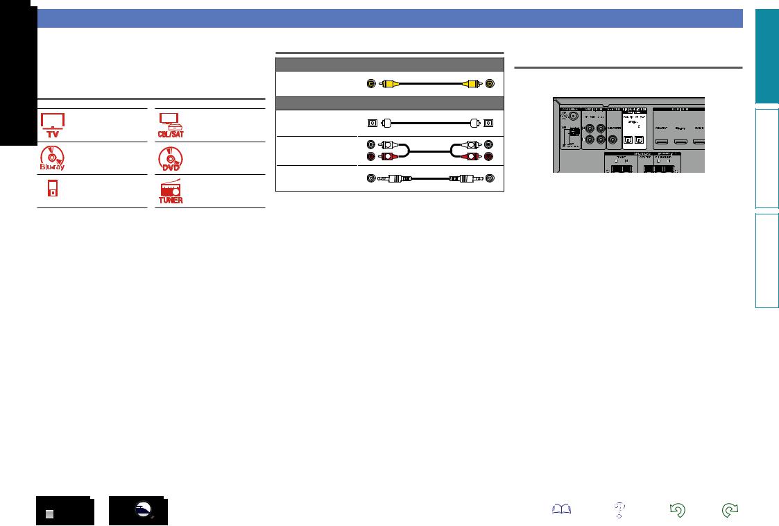
Cables used for connections
|
Video cable (sold separately) |
|
|
Video cable |
|
|
|
|
Audio cable (sold separately) |
|
|
Optical cable |
|
|
|
Audio cable |
L |
L |
|
R |
R |
||
|
|||
Stereo mini plug cable |
|
||
Changing the source assigned to connectors
This unit can change the source that is assigned to the DIGITAL AUDIO IN connectors.
Here, a connection to the DVD player is taken as an example for explanation. The rear panel digital audio input connectors do not have the input connector indication for DVD players (DVD). However, DIGITAL AUDIO IN connectors have the “ASSIGNABLE” indication, which means that you can change the source assigned to these connectors. You can assign DVD players to these connectors to use them for DVD players. If you select “DVD” when you switch the input source for this unit, you can play back the source connected to these connectors.
nnHow to change the source assigned to connectors (vpage 34)
Information instructions Advanced instructions Basic
9
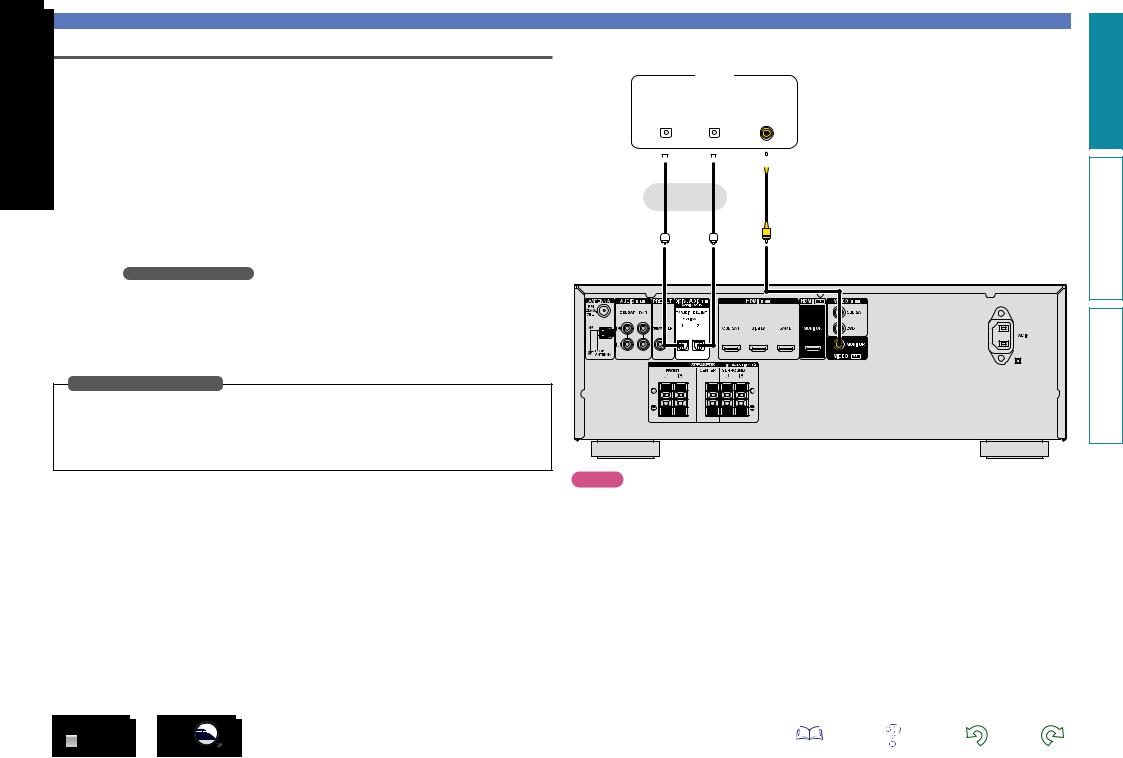
Connecting a TV
•This section describes how to connect when your TV does not support HDMI connections. For instructions on HDMI connections, see “Connecting HDMI devices” (vpage 5).
•To listen to TV audio through this unit, use the optical digital connection.
nnAudio connection
The following methods are available for connecting to this unit. Use either of the methods to make a connection.
The numbers prefixed with connectors indicate the recommendation order. The smaller the number is, the higher playback quality is achieved.
a DIGITAL AUDIO OPTICAL 1 connector DIGITAL AUDIO OPTICAL 2 connector z
When a multichannel audio (digital bit stream audio) is input, this unit decodes the audio to play back surround sound.
zWhen making this type of connection, you must change the settings on this unit. (v Input connector setting )
nnVideo connection
The following methods are available for connecting to this unit.
a VIDEO OUT (MONITOR) connector
This makes an analog video connection.
Input connector setting
When making the following connection, you must change the input connector settings.
a DIGITAL AUDIO OPTICAL 2 connector
Change the default “CBL/SAT” to “TV AUDIO”. For how to change, see “Input Assign” (vpage 34).
Connecting other devices
TV
|
|
AUDIO |
|
|
|
|
|
VIDEO |
|
||
|
|
|
|
|
|
|
|
||||
|
|
|
|
|
|
|
|
|
|
|
|
|
|
|
|
|
|
|
|
|
|
|
|
|
|
|
|
|
|
|
|
|
|
|
|
OPTICAL |
|
|
OPTICAL |
|
|
VIDEO |
|
||||
OUT |
|
|
OUT |
|
|
IN |
|
||||
|
|
|
|
|
|
|
|
|
|
|
|
|
|
|
|
|
|
|
|
|
|
|
|
|
|
|
|
|
|
|
|
|
|
|
|
a a
a a
a
or
NOTE |
•The menu screen is only displayed on TV connected to this unit via HDMI. If your TV is connected to this unit via other video output connectors, perform menu operations while seeing the display on this unit.
•If the VIDEO input connector is to be used, be sure to connect the MONITOR output connector of the unit and the VIDEO input connector of the TV, using a video cable.
Information instructions Advanced instructions Basic
10
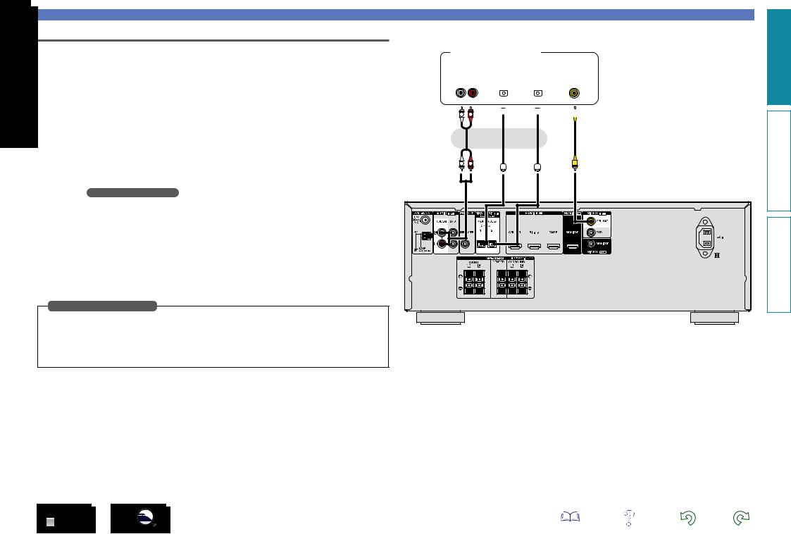
Connecting a set-top box (Satellite tuner/Cable TV)
This section describes how to connect when your satellite tuner or cable TV does not support HDMI connections.
For instructions on HDMI connections, see “Connecting HDMI devices” (vpage 5).
nnAudio connection
The following methods are available for connecting to this unit. Use either of the methods to make a connection.
The numbers prefixed with connectors indicate the recommendation order. The smaller the number is, the higher playback quality is achieved.
a DIGITAL AUDIO OPTICAL 1 connector z
DIGITAL AUDIO OPTICAL 2 connector
When a multichannel audio (digital bit stream audio) is input, this unit decodes the audio to play back surround sound.
zWhen making this type of connection, you must change the settings on this unit. (v Input connector setting )
s AUDIO IN (CBL/SAT) connector
This makes an analog audio connection. This type of connection converts digital audio to analog audio, so the output audio may be degraded compared to connections a.
nnVideo connection
The following methods are available for connecting to this unit.
a VIDEO IN (CBL/SAT) connector
This makes an analog video connection.
Input connector setting
When making the following connection, you must change the input connector settings.
a DIGITAL AUDIO OPTICAL 1 connector
Change the default “TV AUDIO” to “CBL/SAT”. For how to change, see “Input Assign” (vpage 34).
11
Satellite tuner/Cable TV
|
|
|
AUDIO |
|
|
|
|
|
|
|
VIDEO |
|
||
|
|
|
|
|
|
|
|
|
|
|
||||
|
|
|
|
|
|
|
|
|
|
|
|
|
|
|
|
|
|
|
|
|
|
|
|
|
|
|
|
||
|
|
|
|
|
|
|
|
|
|
|
|
|
|
|
AUDIO |
|
OPTICAL |
|
OPTICAL |
|
|
VIDEO |
|
||||||
OUT |
|
|
OUT |
|
OUT |
|
|
OUT |
|
|||||
L R |
|
|
|
|
|
|
|
|
|
|
|
|
|
|
|
|
|
|
|
|
|
|
|
|
|
|
|
|
|
|
|
|
|
|
|
|
|
|
|
|
|
|
|
|
s L 
 R a
R a a
a a
a
or or
L 
 R
R
Connecting other devices
Information instructions Advanced instructions Basic

Connecting other devices
Connecting a Blu-ray Disc player/DVD player
This section describes how to connect a Blu-ray Disc player and DVD player that does not support HDMI connections.
For instructions on HDMI connections, see “Connecting HDMI devices” (vpage 5).
nnAudio connection
The following methods are available for connecting to this unit. Use either of the methods to make a connection.
The numbers prefixed with connectors indicate the recommendation order. The smaller the number is, the higher playback quality is achieved.
a DIGITAL AUDIO OPTICAL 1 connector z DIGITAL AUDIO OPTICAL 2 connector z
When a multichannel audio (digital bit stream audio) is input, this unit decodes the audio to play back surround sound. However, digital bit stream audio signals for HD audios from Blu-ray disc players (such as Dolby Digital Plus and DTS-HD) can not be transmitted.
zWhen making this type of connection, you must change the settings on this unit. (v Input connector setting )
s AUDIO IN (DVD) connector
This makes an analog audio connection. This type of connection converts digital audio to analog audio, so the output audio may be degraded compared to connections a.
nnVideo connection
The following methods are available for connecting to this unit.
a VIDEO IN (DVD) connector
This makes an analog video connection.
Input connector setting
When making the following connection, you must change the input connector settings.
a DIGITAL AUDIO OPTICAL 1 connector
Change the default “TV AUDIO” to “DVD”.
DIGITAL AUDIO OPTICAL 2 connector
Change the default “CBL/SAT” to “DVD”.
For how to change, see “Input Assign” (vpage 34).
Blu-ray Disc player/DVD player
|
|
AUDIO |
|
VIDEO |
AUDIO |
OPTICAL |
OPTICAL |
VIDEO |
|
OUT |
OUT |
OUT |
OUT |
|
L |
R |
|
|
|
s L |
R |
a |
a |
a |
|
|
or |
or |
|
L |
R |
|
|
|
When you want to play back HD Audio (Dolby TrueHD, DTS-HD, Dolby Digital Plus, DTS Express) and Multi-channel PCM with this unit, use an HDMI connection (vpage 5 “Connecting HDMI devices”).
Information instructions Advanced instructions Basic
12

Connecting a portable player
If a portable player is connected via the PORTABLE input jack of the unit, music from the portable player can be played.
Portable
player
AUDIO
AUDIO
OUT
Connecting other devices
Connecting an FM/AM antenna
•Connect the FM antenna or AM loop antenna supplied with the unit to enjoy listening to radio broadcasts.
•After connecting the antenna and receiving a broadcast signal (vpage 17 “Listening to FM/AM broadcasts”), fix the antenna with tape in a position where the background noise level becomes minimal and the sound quality is most clear.
Direction of broadcasting station
AM loop antenna
(supplied)  FM outdoor antenna
nnAM loop antenna assembly
Put |
the stand section |
|
Stand |
1 through the bottom of the |
|
Square |
|
loop |
antenna from the |
Loop |
hole |
rear and bend it forward. |
Projecting |
||
|
|
antenna |
part |
2 Insert the projecting part into the square hole in the stand.
White |
|
|
Black |
75 Ω/ohms |
|
|
coaxial cable |
|
|
FM indoor |
nnUsing the AM loop antenna |
|
Suspending on a wall |
|
|
antenna |
|
|
(supplied) |
Suspend directly on a wall without assembling. |
|
|
Nail, tack, etc.
q |
w |
e |
AM outdoor  antenna Ground
Standing alone
Use the procedure shown above to assemble.
NOTE
•Do not connect two FM antennas simultaneously.
•Even if an external AM antenna is used, do not disconnect the AM loop antenna.
•Make sure the AM loop antenna lead terminals do not touch metal parts of the panel.
•If the signal has noise interference, connect the ground terminal (GND) to reduce noise.
•If you are unable to receive a good broadcast signal, we recommend installing an outdoor antenna. For details, inquire at the retail store where you purchased the unit.
Information instructions Advanced instructions Basic
13
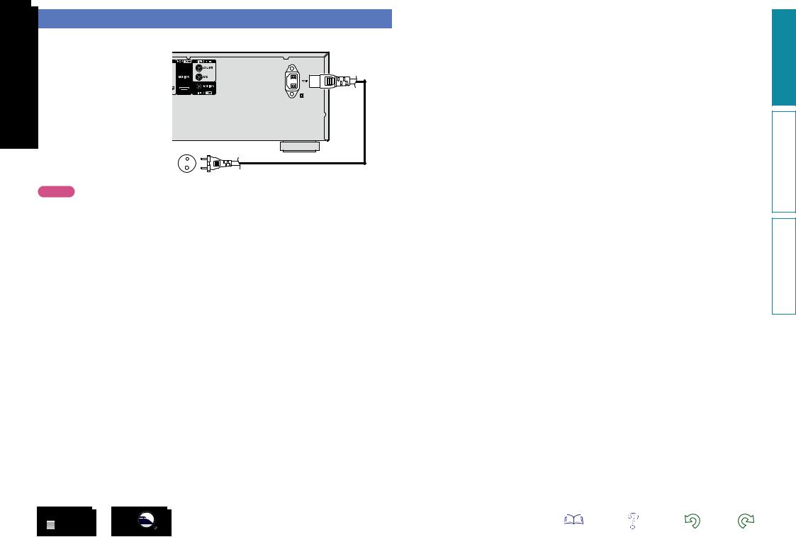
Connecting the power cord
After completing all the connections, insert the power plug into the power outlet.
To household power outlet |
|
(AC 230 V, 50/60 Hz) |
Power cord (supplied) |
|
NOTE
Do not bundle power cords together with connection cables. Doing so can result in humming or noise.
14
Information instructions Advanced instructions Basic
Playback (Basic operation)
nn Turning the power on (vpage 15)
nn Selecting the input source (vpage 15) nn Adjusting the master volume (vpage 16)
nn Turning off the sound temporarily (vpage 16)
nn Switching the brightness of the display
(vpage 16)
nn Playing a Blu-ray Disc player/DVD player
(vpage 16)
nn Playing a portable player (vpage 16) nn Tuning in radio stations (vpage 17)
Selecting a listening mode (Surround mode)
(vpage 21)
Playback (Advanced operation) (vpage 29)
Important information
Before starting playback, make the connections between the different devices and the settings on the unit.
NOTE
Also refer to the operating instructions of the connected devices when playing them.
Turning the power on
Press POWER X to turn on power to
the this unit.
The power indicator flashes green and the power turns on.
You can also switch the power to standby by pressing X on the main unit.
Selecting the input source
Press the input source select button (CBL/SAT, DVD, Blu-ray, GAME, AUX, PORTABLE, TV AUDIO or
TUNER) to be played back.
The desired input source can be selected directly.
You can also use the following operation to select an input source.
nnSelect the input source using the main unit
Use SOURCE SELECT 0 1.
•Use SOURCE SELECT 0 1 switches the input source, as shown below.
CBL/SAT 
 DVD
DVD 
 Blu-ray
 GAME
GAME 
 PORTABLE
 TV AUDIO
 TUNER
TUNER
 AUX
AUX
nnWhen power is switched to standby
Press POWER X.
GPower indicator status in standby modeH
•Normal standby : Off
•When “Pass Through” (vpage 40) is set to “On” : Red
15
Information instructions Advanced instructions Basic
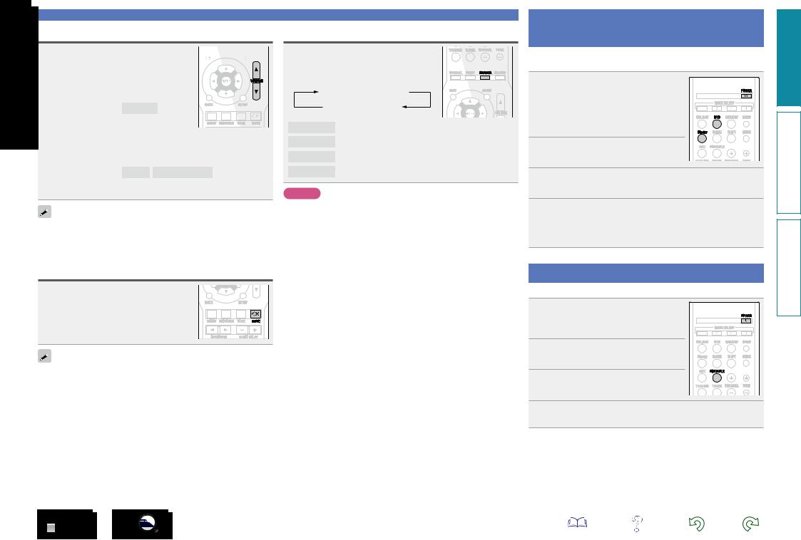
Adjusting the master volume
Use VOLUME df to adjust the 


 volume.


nn When the “Scale” setting (vpage 39) is “0 – 98”
GAdjustable rangeH 0.0 – 98.0
nn When the “Scale” setting (vpage 39) is “–79.5dB –
18.0dB”
GAdjustable rangeH – – –.– –79.5dB – 18.0dB
•The variable range differs according to the input signal and channel level setting.
You can also operate via the main unit. In this case, perform the following operations.
Turn MASTER VOLUME to adjust the volume.
Important information
Switching the brightness of the display
Press DIMMER.
•The display brightness of this unit switches each time the button is pressed.
Bright  Dim
Dim
Off  Dark
Dark
Playing a Blu-ray Disc player/DVD player
The following describes the procedure for playing Blu-ray Disc player/ DVD player.
1
Bright Normal display brightness.
Dim Reduced display brightness.
Dark Very low display brightness.
Off Turns the display off.
NOTE
When the brightness of the display is set to “Off”, the display turns off and appears as if there is no electricity.
2
3 Press Blu-ray or DVD to switch an input source for a player used for playback.
4 Play the Blu-ray Disc player or DVD player.
•Make the necessary settings on the player (language setting, subtitles setting, etc.) beforehand.
Turning off the sound temporarily
Press MUTE :.
•“MUTE” indicator on the display flashes.
•: appears on the TV screen.
•The sound is reduced to the level set at “Mute Level” (vpage 39).
•To cancel, press MUTE : again. Muting can also be cancelled by adjusting the master volume.
Playing a portable player
The following describes the procedure for playing portable player.
1 Connect the portable player
to this unit (vpage 13
“Connecting a portable player”).
2 Press POWER Xto turn on power to the unit.
3 Press PORTABLE to switch the input source to “PORTABLE”.
4 Play the portable player.
Information instructions Advanced instructions Basic
16
Tuning in radio stations
For antenna connections, see “Connecting an FM/AM antenna” (vpage 13).
How to tune in
The modes for receiving FM/AM broadcasts consists of “AUTO” mode that automatically searches available broadcast stations and “MANUAL” mode that lets you tune in using buttons to change the frequency. The default setting is “AUTO”.
In “AUTO” mode, you cannot tune in to radio stations if the reception is not good. If this is the case, then use the “MANUAL” to tune in.
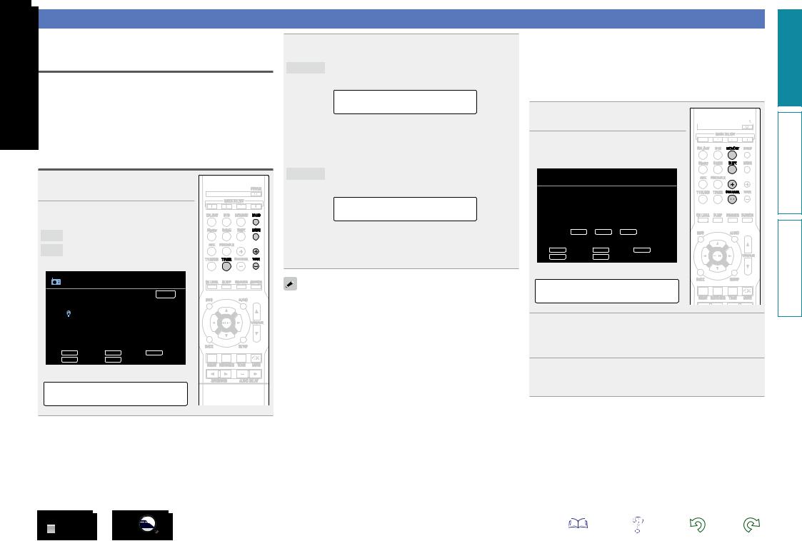
Listening to FM/AM broadcasts
1 Press TUNER to switch the input source to “TUNER”.
2 Press BAND to select “FM” or “AM”.
FM When listening to an FM broadcast.
AM When listening to an AM broadcast.
GTV ScreenH
TUNER
|
|
|
|
AUTO |
|
|
|
|
Now Playing |
FM 87.50MHz |
|
|
||
|
|
|
|
A1 |
|
|
|
|
|
TUNE |
Tuning |
BAND |
Band |
MODE Mode |
CHANNEL |
Preset |
MEMORY |
Memory |
|
GDisplay of this unitH
A1 FM 87.50MHz
3 Tune in the desired broadcast station.
AUTO Automatically tune to the station.
q Press MODE to select “AUTO”.
MODE:AUTO
wPress TUNE + or TUNE – to select the station you want to hear.
•The frequency changes in steps each time the button is pressed.
MANUAL Manually tune to the station.
q Press MODE to select “MANUAL”.
MODE:MANUAL
wPress TUNE + or TUNE – to select the station you want to hear.
•The frequency changes in steps each time the button is pressed.
When tuning in stations manually, press and hold TUNE + or TUNE – to change frequencies continuously.
17
nnPresetting radio stations (Manual preset)
Your favorite broadcast stations can be preset so that you can tune them in easily. Up to 56 stations can be preset.
•Stations can be preset automatically at “Auto Preset” (vpage 34). If “Auto Preset” is performed after performing “Manual preset”, the “Manual preset” settings will be overwritten.
1Tune in the broadcast station you
want to preset. 
2 Press MEMORY.
GTV ScreenH
 TUNER
TUNER
|
|
|
To store preset: |
|
|
|
|
|
|
|
|
|
|
|
|
|
|
|
|
||
|
|
|
select |
A1-G8 |
|
|
|
|
|
|
|
|
SHIFT |
CHANNEL |
MEMORY |
A1 |
|
|
|
|
|
|
|
|
|
|
||||||
|
|
|
|
|
|
|
|
|||
|
|
|
|
|
|
|
|
|
|
|
|
TUNE |
Tuning |
BAND |
Band |
MODE Mode |
|
|
|
||
|
CHANNEL |
Preset |
MEMORY |
Memory |
|
|
|
|
|
|
GDisplay of this unitH
Storing Station
3 Press CHANNEL + or CHANNEL – to select the preset number.
•Press SHIFT, and then the block (A – G) can be selected.
4 Press MEMORY again to complete the setting.
•To preset other stations, repeat steps 1 to 4.
Information instructions Advanced instructions Basic
Loading...