

Page 1
GE Healthcare
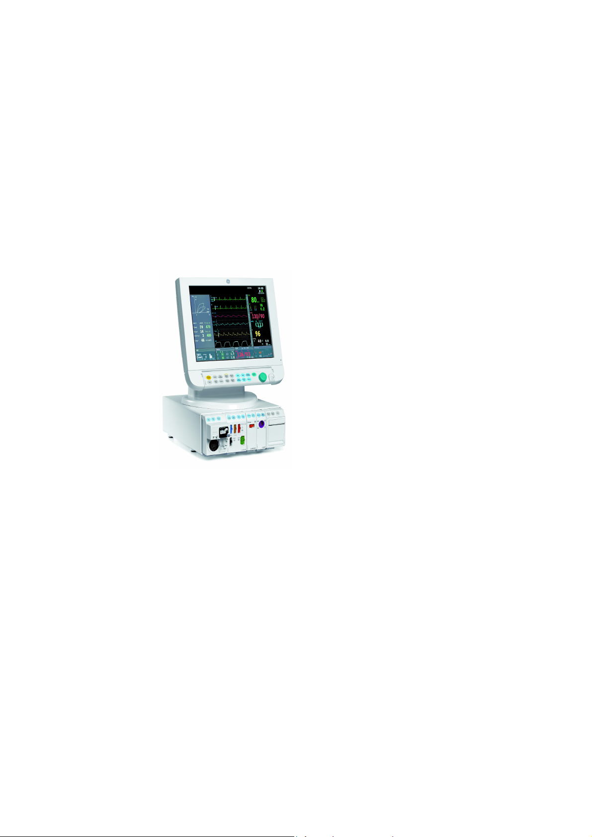
Datex-Ohmeda S/5
Anesthesia Monitor
TM
TM
Datex-Ohmeda S/5
Critical Care Monitor
Technical Reference Manual
Conformity according to the Council Directive 93/42/EEC concerning Medical Devices
CAUTION: U.S. Federal law restricts this device to sale by or on the order of a licensed medical practitioner.
Outside the USA, check local laws for any restriction that may apply.
All specifications subject to change without notice.
Order code M1162897
st
edition
1
June 25, 2009
GE Healthcare Finland Oy
Helsinki, Finland
P.O. Box 900
FI-00031 GE, FINLAND
Tel: +358 10 39411
Fax: +358 9 1463310
www.gehealthcare.com
Copyright © 2009 General Electric Company. All rights reserved.
Madison, WI 53707-7550, USA
Datex-Ohmeda Inc.
Tel: +1 608 221 1551
Fax: +1 608 222 9147
P.O. Box 7550
Page 2

Intended purpose (Indications for use)
The Datex-Ohmeda S/5 Anesthesia Monitor with L-ANE07 or L-ANE07A software is intended for
multiparameter patient monitoring with optional patient care documentation.
The S/5 Anesthesia Monitor with L-ANE07 and L-ANE07A software is indicated for monitoring of
hemodynamic (including arrhythmia and ST-segment analysis), respiratory, ventilatory,
gastrointestinal/regional perfusion, Entropy (State Entropy and Response Entropy) and neurophysiological
status of all hospital patients.
When the BIS module is used with the S/5 Anesthesia Monitor with L-ANE07 and L-ANE07A, it is intended
for use by personnel trained in its proper use. It is intended for use on adult and pediatric patients within a
hospital or medical facility providing patient care to monitor the state of the brain by data acquisition of
EEG signals. The Bispectral index (BIS), a processed EEG variable, and one component of the BIS module,
may be used in adults as an aid in monitoring the effects of certain anesthetic agents. The Bispectral
index is a complex technology, intended for use only as an adjunct to clinical judgement and training. In
addition, the clinical utility, risk/benefit, and application of BIS have not undergone full evaluation in the
pediatric population.
The S/5 Anesthesia Monitor with L-ANE07 and L-ANE07A software is also indicated for documenting
patient care related information.
The S/5 Anesthesia Monitor with L-ANE07 and L-ANE07A software is indicated for use by qualified
medical personnel only.
The Datex-Ohmeda S/5 Critical Care Monitor with L-ICU07 or L-ICU07A software is intended for
multiparameter patient monitoring.
The S/5 Critical Care Monitor with L-ICU07 and L-ICU07A software is indicated for monitoring of
hemodynamic (including arrhythmia and ST-segment analysis), respiratory, ventilatory,
gastrointestinal/regional perfusion and neurophysiological status of all hospital patients.
When the BIS module is used with the S/5 Critical Care Monitor with L-ICU07 and L-ICU07A, it is intended
for use by personnel trained in its proper use. It is intended for use on adult and pediatric patients within
a hospital or medical facility providing patient care to monitor the state of the brain by data acquisition of
EEG signals. The Bispectral index (BIS), a processed EEG variable, and one component of the BIS module,
may be used in adults as an aid in monitoring the effects of certain anesthetic agents. The Bispectral
index is a complex technology, intended for use only as an adjunct to clinical judgement and training. In
addition, the clinical utility, risk/benefit, and application of BIS have not undergone full evaluation in the
pediatric population.
The S/5 Critical Care Monitor with L-ICU07 and L-ICU07A software is indicated for use by qualified medical
personnel only.
Classifications
In accordance with IEC 60601-1
Class I and internally powered equipment – the type of protection against electric shock.
Type BF or CF equipment. The degree of protection against electric shock is indicated by a symbol on
each parameter module.
Equipment not suitable for use in the presence of a flammable anesthetic mixture with air or with oxygen
or nitrous oxide.
Continuous operation according to the mode of operation.
In accordance with IEC 60529
With F-CU8 Central Unit: IPX0 - the degree of protection against harmful ingress of water.
With F-CU5(P) Central Unit: IPX1 - the degree of protection against harmful ingress of water.
In accordance with EU Medical Device Directive
The Datex-Ohmeda S/5 Anesthesia Monitor is classified as IIb.
The Datex-Ohmeda S/5 Critical Care Monitor is classified as IIb.
In accordance with CISPR 11:
Group 1, Class A
• Group 1 contains all ISM (industrial, scientific and medical) equipment in which there is intentionally
generated and/or used conductively coupled radio-frequency energy which is necessary for the
internal functioning of the equipment itself.
• Class A equipment is suitable for use in all establishments other than domestic and those directly
connected the public low voltage power supply network which supplies buildings used for domestic
purposes.
Page 3

Responsibility of the manufacturer
GE Healthcare Finland Oy (GE) is responsible for the effects on safety, reliability and performance of the
equipment only if:
• assembly, extensions, readjustments, modifications, servicing and repairs are carried out by
personnel authorized by GE.
• the electrical installation of the monitor room complies with appropriate requirements.
• the equipment is used in accordance with the "User's Guide" and serviced and maintained in
accordance with the “Technical Reference Manual”.
Trademarks
Datex, Ohmeda, S/5, D-lite, D-lite+, Pedi-lite, Pedi-lite+, D-fend, D-fend+, Mini D-fend, OxyTip+, MemCard,
ComWheel, ComBar, EarSat, FingerSat, FlexSat, PatientO
are trademarks of GE Healthcare Finland Oy. All other product and company names are property of their
respective owners.
A portion of the Entropy software is derived from the RSA Data Security, Inc. MD5 Message-Digest
Algorithm.
, Patient Spirometry, Entropy and Tonometrics
2
Masimo SET
Masimo SET is a licensed trademark of Masimo Corporation.
Product availability
Some of the products mentioned in this manual may not be available in all countries.
Please, consult your local representative for the availability.
Page 4

Page 5
Datex-Ohmeda S/5TM Anesthesia and Critical Care Monitors
Technical Reference Manual, Order code: M1162897
Document No. Updated Description
1st edition
Part I, General Service Guide
M1137263-004 Introduction, System description, Installation,
Interfacing, Functional check, General
troubleshooting
M1125633-006 Planned Maintenance Instructions 2
Part II, Product Service Guide
Document No. Updated Description
M1137266 - 002 Service Menu, L-ANE07(A), L-ICU07(A) 1
M1125635 - 005 8-Module Frame, F-CU8 2
M1125636 - 005 5-Module Frame, F-CU5(P) 3
M1125637 - 004 CPU Board, B-CPU6 4
M1137269 - 002 UPINET Board, B-UPI4NET 5
M1137272 - 002 Displays and Display Controller Boards 6
M1125639 - 003 Command Bars 7
M1125641 - 003 Extension Frame, F-EXT, Extension Module, E-EXT 8
M1137274 - 001 AM, CCM Spare Parts 9
1
1
Document no. M1137263-04
Page 6

Datex-Ohmeda S/5 Anesthesia and Critical Care Monitors
2
Document no. M1137263-04
Page 7

Table of contents
Table of contents
Table of contents i
Table of figures iv
List of tables v
About this manual 1
1Introduction 3
1.1 Symbols . . . . . . . . . . . . . . . . . . . . . . . . . . . . . . . . . . . . . . . . . . . . . . . . . . . . . . . . . . . . . . . . . . . . . . . . . . . . . . 4
1.1.1 Symbols on transport packaging. . . . . . . . . . . . . . . . . . . . . . . . . . . . . . . . . . . . . . . . . . . . . . . . 4
1.1.2 Symbols on equipment . . . . . . . . . . . . . . . . . . . . . . . . . . . . . . . . . . . . . . . . . . . . . . . . . . . . . . . . . 5
1.1.3 Equipment safety symbols. . . . . . . . . . . . . . . . . . . . . . . . . . . . . . . . . . . . . . . . . . . . . . . . . . . . . . 6
1.1.4 Other symbols . . . . . . . . . . . . . . . . . . . . . . . . . . . . . . . . . . . . . . . . . . . . . . . . . . . . . . . . . . . . . . . . . 7
1.2 Safety . . . . . . . . . . . . . . . . . . . . . . . . . . . . . . . . . . . . . . . . . . . . . . . . . . . . . . . . . . . . . . . . . . . . . . . . . . . . . . . 11
1.2.1 Safety precautions . . . . . . . . . . . . . . . . . . . . . . . . . . . . . . . . . . . . . . . . . . . . . . . . . . . . . . . . . . . . 11
1.2.2 ESD precautionary procedures . . . . . . . . . . . . . . . . . . . . . . . . . . . . . . . . . . . . . . . . . . . . . . . . . 15
1.2.3 Disposal . . . . . . . . . . . . . . . . . . . . . . . . . . . . . . . . . . . . . . . . . . . . . . . . . . . . . . . . . . . . . . . . . . . . . . 15
2 System description 17
2.1 Introduction . . . . . . . . . . . . . . . . . . . . . . . . . . . . . . . . . . . . . . . . . . . . . . . . . . . . . . . . . . . . . . . . . . . . . . . . . 17
2.2 Bus structure . . . . . . . . . . . . . . . . . . . . . . . . . . . . . . . . . . . . . . . . . . . . . . . . . . . . . . . . . . . . . . . . . . . . . . . . 17
2.3 Distributed processing . . . . . . . . . . . . . . . . . . . . . . . . . . . . . . . . . . . . . . . . . . . . . . . . . . . . . . . . . . . . . . . 18
2.4 Module communication . . . . . . . . . . . . . . . . . . . . . . . . . . . . . . . . . . . . . . . . . . . . . . . . . . . . . . . . . . . . . . 18
2.5 Software loading. . . . . . . . . . . . . . . . . . . . . . . . . . . . . . . . . . . . . . . . . . . . . . . . . . . . . . . . . . . . . . . . . . . . . 19
2.6 Parameter modules . . . . . . . . . . . . . . . . . . . . . . . . . . . . . . . . . . . . . . . . . . . . . . . . . . . . . . . . . . . . . . . . . . 20
3 System installation 21
3.1 Unpacking instructions. . . . . . . . . . . . . . . . . . . . . . . . . . . . . . . . . . . . . . . . . . . . . . . . . . . . . . . . . . . . . . . 21
3.2 Choosing location. . . . . . . . . . . . . . . . . . . . . . . . . . . . . . . . . . . . . . . . . . . . . . . . . . . . . . . . . . . . . . . . . . . . 21
3.3 Central Unit; S/5 8-Module Frame, F-CU8 . . . . . . . . . . . . . . . . . . . . . . . . . . . . . . . . . . . . . . . . . . . . . 22
3.3.1 Connecting to mains . . . . . . . . . . . . . . . . . . . . . . . . . . . . . . . . . . . . . . . . . . . . . . . . . . . . . . . . . . 22
3.3.2 Connecting to the Datex-Ohmeda Network. . . . . . . . . . . . . . . . . . . . . . . . . . . . . . . . . . . . . 22
3.3.3 Inserting the parameter modules . . . . . . . . . . . . . . . . . . . . . . . . . . . . . . . . . . . . . . . . . . . . . . 23
3.3.4 E-PSM(P) Mounting Accessories . . . . . . . . . . . . . . . . . . . . . . . . . . . . . . . . . . . . . . . . . . . . . . . . 24
3.3.5 Positioning PC boards . . . . . . . . . . . . . . . . . . . . . . . . . . . . . . . . . . . . . . . . . . . . . . . . . . . . . . . . . 26
3.3.6 Replacing PC boards . . . . . . . . . . . . . . . . . . . . . . . . . . . . . . . . . . . . . . . . . . . . . . . . . . . . . . . . . . 27
3.3.7 Performing Factory Reset. . . . . . . . . . . . . . . . . . . . . . . . . . . . . . . . . . . . . . . . . . . . . . . . . . . . . . 28
3.4 Central Unit; S/5 5-Module Frame, F-CU5. . . . . . . . . . . . . . . . . . . . . . . . . . . . . . . . . . . . . . . . . . . . . . 28
3.4.1 Mounting the Frame. . . . . . . . . . . . . . . . . . . . . . . . . . . . . . . . . . . . . . . . . . . . . . . . . . . . . . . . . . . 29
3.4.2 Connecting to mains . . . . . . . . . . . . . . . . . . . . . . . . . . . . . . . . . . . . . . . . . . . . . . . . . . . . . . . . . . 30
3.4.3 Connecting to the Datex-Ohmeda Network. . . . . . . . . . . . . . . . . . . . . . . . . . . . . . . . . . . . . 30
3.4.4 Inserting the parameter modules . . . . . . . . . . . . . . . . . . . . . . . . . . . . . . . . . . . . . . . . . . . . . . 31
3.4.5 Positioning PC boards . . . . . . . . . . . . . . . . . . . . . . . . . . . . . . . . . . . . . . . . . . . . . . . . . . . . . . . . . 32
3.4.6 Replacing PC boards . . . . . . . . . . . . . . . . . . . . . . . . . . . . . . . . . . . . . . . . . . . . . . . . . . . . . . . . . . 33
Document no. M1137263-04
i
Page 8

Datex-Ohmeda S/5 Anesthesia and Critical Care Monitors
3.4.7 Performing Factory Reset. . . . . . . . . . . . . . . . . . . . . . . . . . . . . . . . . . . . . . . . . . . . . . . . . . . . . . 33
3.5 Displays . . . . . . . . . . . . . . . . . . . . . . . . . . . . . . . . . . . . . . . . . . . . . . . . . . . . . . . . . . . . . . . . . . . . . . . . . . . . . 34
3.5.1 Main displays . . . . . . . . . . . . . . . . . . . . . . . . . . . . . . . . . . . . . . . . . . . . . . . . . . . . . . . . . . . . . . . . . 34
3.5.2 Secondary displays. . . . . . . . . . . . . . . . . . . . . . . . . . . . . . . . . . . . . . . . . . . . . . . . . . . . . . . . . . . . 34
3.5.3 3rd display . . . . . . . . . . . . . . . . . . . . . . . . . . . . . . . . . . . . . . . . . . . . . . . . . . . . . . . . . . . . . . . . . . . . 34
3.5.4 Display installation . . . . . . . . . . . . . . . . . . . . . . . . . . . . . . . . . . . . . . . . . . . . . . . . . . . . . . . . . . . . 34
3.5.5 15” Flat Panel Display, D-FPD15 . . . . . . . . . . . . . . . . . . . . . . . . . . . . . . . . . . . . . . . . . . . . . . . . 35
3.5.6 12” LCD Display, D-LCC12A. . . . . . . . . . . . . . . . . . . . . . . . . . . . . . . . . . . . . . . . . . . . . . . . . . . . 36
3.5.7 19” medical grade display . . . . . . . . . . . . . . . . . . . . . . . . . . . . . . . . . . . . . . . . . . . . . . . . . . . . . 37
3.6 Display controller boards. . . . . . . . . . . . . . . . . . . . . . . . . . . . . . . . . . . . . . . . . . . . . . . . . . . . . . . . . . . . . 38
3.6.1 Jumper settings . . . . . . . . . . . . . . . . . . . . . . . . . . . . . . . . . . . . . . . . . . . . . . . . . . . . . . . . . . . . . . . 38
3.6.2 Resolution selection for optional B-DISPX . . . . . . . . . . . . . . . . . . . . . . . . . . . . . . . . . . . . . . . 39
3.6.3 Resolution selection for primary display . . . . . . . . . . . . . . . . . . . . . . . . . . . . . . . . . . . . . . . . 39
3.7 S/5 Remote Controller, K-REMCO. . . . . . . . . . . . . . . . . . . . . . . . . . . . . . . . . . . . . . . . . . . . . . . . . . . . . . 39
3.8 S/5 Airway Modules . . . . . . . . . . . . . . . . . . . . . . . . . . . . . . . . . . . . . . . . . . . . . . . . . . . . . . . . . . . . . . . . . . 40
3.8.1 S/5 Compact Airway Modules, E-xxxx . . . . . . . . . . . . . . . . . . . . . . . . . . . . . . . . . . . . . . . . . . 40
3.8.2 Sample gas exhaust. . . . . . . . . . . . . . . . . . . . . . . . . . . . . . . . . . . . . . . . . . . . . . . . . . . . . . . . . . . 40
3.9 Record Keeping Keyboard for Anesthesia, K-ARKB . . . . . . . . . . . . . . . . . . . . . . . . . . . . . . . . . . . . . 42
3.9.1 Connection to Central Unit. . . . . . . . . . . . . . . . . . . . . . . . . . . . . . . . . . . . . . . . . . . . . . . . . . . . . 42
3.9.2 Connection to LCD Display, D-LCC12A . . . . . . . . . . . . . . . . . . . . . . . . . . . . . . . . . . . . . . . . . . 42
3.10 ARK Barcode Reader, N-SCAN (optional) . . . . . . . . . . . . . . . . . . . . . . . . . . . . . . . . . . . . . . . . . . . . . . . 43
3.10.1 Connection to Central Unit/LCD Display or D-LCC12A . . . . . . . . . . . . . . . . . . . . . . . . . . . 43
3.11 S/5 Extension Frame, F-EXT4, with F-CU8 only . . . . . . . . . . . . . . . . . . . . . . . . . . . . . . . . . . . . . . . . . 44
3.11.1 Mounting of Extension Frame, F-EXT4 . . . . . . . . . . . . . . . . . . . . . . . . . . . . . . . . . . . . . . . . . . 45
3.11.2 Connection to Central Unit. . . . . . . . . . . . . . . . . . . . . . . . . . . . . . . . . . . . . . . . . . . . . . . . . . . . . 45
3.11.3 Inserting the parameter modules . . . . . . . . . . . . . . . . . . . . . . . . . . . . . . . . . . . . . . . . . . . . . . 45
3.11.4 Troubleshooting. . . . . . . . . . . . . . . . . . . . . . . . . . . . . . . . . . . . . . . . . . . . . . . . . . . . . . . . . . . . . . . 45
4Interfacing 47
4.1 Interfacing external monitors via Interface Module, E-INT. . . . . . . . . . . . . . . . . . . . . . . . . . . . . . 47
4.1.1 Connection to external Datex-Ohmeda monitors . . . . . . . . . . . . . . . . . . . . . . . . . . . . . . . 48
4.1.2 Connection to Critikon Dinamap 1846SX, Abbott Oximetrix 3 and
Baxter Explorer. . . . . . . . . . . . . . . . . . . . . . . . . . . . . . . . . . . . . . . . . . . . . . . . . . . . . . . . . . . . . . . . 49
4.1.3 Connection to Baxter Vigilance . . . . . . . . . . . . . . . . . . . . . . . . . . . . . . . . . . . . . . . . . . . . . . . . 49
4.1.4 Connection to Nellcor N-100 and N-1000. . . . . . . . . . . . . . . . . . . . . . . . . . . . . . . . . . . . . . . 49
4.1.5 Connection to Nellcor N-200. . . . . . . . . . . . . . . . . . . . . . . . . . . . . . . . . . . . . . . . . . . . . . . . . . . 49
4.2 Interfacing external bedside devices via Device Interfacing Solutions, N-DISxxx. . . . . . . . 51
4.2.1 Device Interfacing Solution components . . . . . . . . . . . . . . . . . . . . . . . . . . . . . . . . . . . . . . . 52
4.2.2 Connections . . . . . . . . . . . . . . . . . . . . . . . . . . . . . . . . . . . . . . . . . . . . . . . . . . . . . . . . . . . . . . . . . . 52
4.2.3 Mounting . . . . . . . . . . . . . . . . . . . . . . . . . . . . . . . . . . . . . . . . . . . . . . . . . . . . . . . . . . . . . . . . . . . . . 53
4.2.4 Selecting the external device . . . . . . . . . . . . . . . . . . . . . . . . . . . . . . . . . . . . . . . . . . . . . . . . . . 54
4.2.5 Functional check . . . . . . . . . . . . . . . . . . . . . . . . . . . . . . . . . . . . . . . . . . . . . . . . . . . . . . . . . . . . . . 55
4.2.6 Selecting the parameter data source. . . . . . . . . . . . . . . . . . . . . . . . . . . . . . . . . . . . . . . . . . . 55
4.3 Interfacing Datex-Ohmeda Anesthesia Delivery Unit. . . . . . . . . . . . . . . . . . . . . . . . . . . . . . . . . . . 56
4.3.1 Interconnection . . . . . . . . . . . . . . . . . . . . . . . . . . . . . . . . . . . . . . . . . . . . . . . . . . . . . . . . . . . . . . . 56
4.3.2 Setting interfacing parameters on the S/5 Anesthesia Delivery Unit . . . . . . . . . . . . . . 56
4.3.3 Setting interfacing parameters on the S/5 Anesthesia Monitor. . . . . . . . . . . . . . . . . . . 56
4.4 Interfacing Dräger Cicero, Cato, Julian and Narkomed 2C (by NAD) . . . . . . . . . . . . . . . . . . . . 57
4.4.1 Interconnection . . . . . . . . . . . . . . . . . . . . . . . . . . . . . . . . . . . . . . . . . . . . . . . . . . . . . . . . . . . . . . . 58
ii
Document no. M1137263-04
Page 9

Table of contents
4.4.2 Setting communication parameters. . . . . . . . . . . . . . . . . . . . . . . . . . . . . . . . . . . . . . . . . . . . 58
4.4.3 Setting interfacing parameters on the S/5 Anesthesia Monitor or
S/5 Critical Care Monitor . . . . . . . . . . . . . . . . . . . . . . . . . . . . . . . . . . . . . . . . . . . . . . . . . . . . . . . 58
4.5 Interfacing printer . . . . . . . . . . . . . . . . . . . . . . . . . . . . . . . . . . . . . . . . . . . . . . . . . . . . . . . . . . . . . . . . . . . 60
4.5.1 Interconnection . . . . . . . . . . . . . . . . . . . . . . . . . . . . . . . . . . . . . . . . . . . . . . . . . . . . . . . . . . . . . . . 60
4.5.2 Setting interfacing parameters on the printer. . . . . . . . . . . . . . . . . . . . . . . . . . . . . . . . . . . 60
4.5.3 Setting interfacing parameters on the S/5 Anesthesia Monitor or
S/5 Critical Care Monitor . . . . . . . . . . . . . . . . . . . . . . . . . . . . . . . . . . . . . . . . . . . . . . . . . . . . . . . 60
4.6 Interfacing computer . . . . . . . . . . . . . . . . . . . . . . . . . . . . . . . . . . . . . . . . . . . . . . . . . . . . . . . . . . . . . . . . 60
4.7 Output signals . . . . . . . . . . . . . . . . . . . . . . . . . . . . . . . . . . . . . . . . . . . . . . . . . . . . . . . . . . . . . . . . . . . . . . . 61
4.7.1 UPI4NET Board output signals . . . . . . . . . . . . . . . . . . . . . . . . . . . . . . . . . . . . . . . . . . . . . . . . . 61
4.7.2 Digital outputs . . . . . . . . . . . . . . . . . . . . . . . . . . . . . . . . . . . . . . . . . . . . . . . . . . . . . . . . . . . . . . . . 61
4.7.3 Analog outputs. . . . . . . . . . . . . . . . . . . . . . . . . . . . . . . . . . . . . . . . . . . . . . . . . . . . . . . . . . . . . . . . 62
4.7.4 S/5 Pressure Temp Module, E-PT, output signals. . . . . . . . . . . . . . . . . . . . . . . . . . . . . . . . . 62
5 Functional check 63
5.1 Recommended tools . . . . . . . . . . . . . . . . . . . . . . . . . . . . . . . . . . . . . . . . . . . . . . . . . . . . . . . . . . . . . . . . . 63
5.1.1 Hemodynamic patient simulators . . . . . . . . . . . . . . . . . . . . . . . . . . . . . . . . . . . . . . . . . . . . . . 65
5.2 Visual inspection. . . . . . . . . . . . . . . . . . . . . . . . . . . . . . . . . . . . . . . . . . . . . . . . . . . . . . . . . . . . . . . . . . . . . 65
5.3 Functional inspection . . . . . . . . . . . . . . . . . . . . . . . . . . . . . . . . . . . . . . . . . . . . . . . . . . . . . . . . . . . . . . . . 66
5.3.1 General . . . . . . . . . . . . . . . . . . . . . . . . . . . . . . . . . . . . . . . . . . . . . . . . . . . . . . . . . . . . . . . . . . . . . . . 66
5.3.2 Display(s) . . . . . . . . . . . . . . . . . . . . . . . . . . . . . . . . . . . . . . . . . . . . . . . . . . . . . . . . . . . . . . . . . . . . . 67
5.3.3 Keyboard(s) . . . . . . . . . . . . . . . . . . . . . . . . . . . . . . . . . . . . . . . . . . . . . . . . . . . . . . . . . . . . . . . . . . . 67
5.3.4 5-Module Central Unit, F-CU5/ 8-Module Central Unit, F-CU8 . . . . . . . . . . . . . . . . . . . . 68
5.3.5 Extension Frame, F-EXT4 . . . . . . . . . . . . . . . . . . . . . . . . . . . . . . . . . . . . . . . . . . . . . . . . . . . . . . 68
5.3.6 Compact Airway Module, E-CXXXXX . . . . . . . . . . . . . . . . . . . . . . . . . . . . . . . . . . . . . . . . . . . . 68
5.3.7 Single width Airway Module, E-miniC . . . . . . . . . . . . . . . . . . . . . . . . . . . . . . . . . . . . . . . . . . . 69
5.3.8 Multiparameter Hemodynamic Modules. . . . . . . . . . . . . . . . . . . . . . . . . . . . . . . . . . . . . . . . 69
5.3.9 Pressure/Pressure Temp Modules, E-P, E-PT . . . . . . . . . . . . . . . . . . . . . . . . . . . . . . . . . . . . . 70
5.3.10 Dual pressure Module, E-PP . . . . . . . . . . . . . . . . . . . . . . . . . . . . . . . . . . . . . . . . . . . . . . . . . . . . 70
5.3.11 Cardiac Output Modules, E-COP, E-COPSv. . . . . . . . . . . . . . . . . . . . . . . . . . . . . . . . . . . . . . . 70
5.3.12 Masimo Compatible Saturation module, E-MASIMO . . . . . . . . . . . . . . . . . . . . . . . . . . . . . 71
5.3.13 Nellcor Compatible Saturation module, E-NSATX . . . . . . . . . . . . . . . . . . . . . . . . . . . . . . . . 71
5.3.14 BIS Module, E-BIS. . . . . . . . . . . . . . . . . . . . . . . . . . . . . . . . . . . . . . . . . . . . . . . . . . . . . . . . . . . . . . 71
5.3.15 Entropy Module, E-ENTROPY . . . . . . . . . . . . . . . . . . . . . . . . . . . . . . . . . . . . . . . . . . . . . . . . . . . 71
5.3.16 Memory Module, E-MEM . . . . . . . . . . . . . . . . . . . . . . . . . . . . . . . . . . . . . . . . . . . . . . . . . . . . . . . 71
5.3.17 Recorder module . . . . . . . . . . . . . . . . . . . . . . . . . . . . . . . . . . . . . . . . . . . . . . . . . . . . . . . . . . . . . . 72
5.3.18 Network connection . . . . . . . . . . . . . . . . . . . . . . . . . . . . . . . . . . . . . . . . . . . . . . . . . . . . . . . . . . . 72
5.3.19 Interface Module, E-INT . . . . . . . . . . . . . . . . . . . . . . . . . . . . . . . . . . . . . . . . . . . . . . . . . . . . . . . . 72
5.3.20 Interface module for PSM, E-INTPSM . . . . . . . . . . . . . . . . . . . . . . . . . . . . . . . . . . . . . . . . . . . 72
5.3.21 Device Interfacing Solution, N-DISxxx . . . . . . . . . . . . . . . . . . . . . . . . . . . . . . . . . . . . . . . . . . 72
5.3.22 General . . . . . . . . . . . . . . . . . . . . . . . . . . . . . . . . . . . . . . . . . . . . . . . . . . . . . . . . . . . . . . . . . . . . . . . 73
6 General troubleshooting 75
6.1 Software troubleshooting . . . . . . . . . . . . . . . . . . . . . . . . . . . . . . . . . . . . . . . . . . . . . . . . . . . . . . . . . . . . 76
Appendix A: Functional check form, Datex-Ohmeda S/5 AM, CCM A-1
Appendix B: ElectroMagnetic Compatibility B-1
Document no. M1137263-04
iii
Page 10

Datex-Ohmeda S/5 Anesthesia and Critical Care Monitors
Table of figures
Figure 1 Datex-Ohmeda S/5 Anesthesia Monitor system........................................................................................................... 3
Figure 2 General bus structure of S/5 system ................................................................................................................................17
Figure 3 Distributed processing in S/5 system ...............................................................................................................................18
Figure 4 Principle of UPI section operation ......................................................................................................................................19
Figure 5 Software loading ........................................................................................................................................................................19
Figure 6 General structure of parameter modules with patient isolation.........................................................................20
Figure 7 Central Unit: S/5 8-Module Frame, F-CU8 ......................................................................................................................22
Figure 8 Module insert................................................................................................................................................................................23
Figure 9 E-PSM(P) mounting accessories ..........................................................................................................................................24
Figure 10 Rear view and positioning, F-CU8 (-12 shown).............................................................................................................26
Figure 11 Service reset button..................................................................................................................................................................27
Figure 12 F-CU5 parts connected with cables..................................................................................................................................29
Figure 13 Two F-CU5s connected to one F-CPU ..............................................................................................................................29
Figure 14 PC boards.......................................................................................................................................................................................32
Figure 15 Service reset button..................................................................................................................................................................33
Figure 16 Display options............................................................................................................................................................................34
Figure 17 Address dip switch settings, B-DISPX ...............................................................................................................................38
Figure 18 Resolution dip switch settings, B-DISPX ..........................................................................................................................39
Figure 19 Compact Airway Module, E-XXXX .......................................................................................................................................40
Figure 20 Scavenging through ventilator reservoir ........................................................................................................................41
Figure 21 Connecting the gas module to the scavenging connector of S/5 Avance .....................................................41
Figure 22 Sample gas returned to patient circuit in ADU.............................................................................................................42
Figure 23 Barcode Reader connected to LCD Display...................................................................................................................43
Figure 24 N-SCAN Barcode Reader connection directly to the keyboard...........................................................................44
Figure 25 S/5 Extension Frame, F-EXT4................................................................................................................................................44
Figure 26 Connection cables and LED indicators ............................................................................................................................53
Figure 27 An example of interfacing external devices with Device Interfacing Solution..............................................54
Figure 28 S/5 AM, CCM general troubleshooting flowchart........................................................................................................75
iv
Document no. M1137263-04
Page 11

List of tables
List of tables
Table 1 Transference of parameters, Datex-Ohmeda monitors ...................................................................... 48
Table 2 Transference of parameters, external monitors...................................................................................... 48
Table 3 DIS modules and interfaced devices............................................................................................................. 51
Table 4 Parameters transferred from S/5 Anesthesia Monitor to S/5 Anesthesia Delivery Unit....... 56
Table 5 Events transferred from S/5 Anesthesia Delivery Unit to the S/5 Anesthesia Monitor.......... 57
Table 6 Parameters transferred from Dräger Cicero monitor to S/5 Anesthesia Monitor or
S/5 Critical Care Monitor ..................................................................................................................................... 58
Table 7 Parameters transferred from Dräger Cato, Julian and Narkomed 2C (NAD) monitor to
the S/5Anesthesia Monitor or S/5Critical Care Monitor........................................................................ 59
Table 8 Coding element connector, X4......................................................................................................................... 61
Table 9 Defib & IABP sync connector, X7 (B-UPI4NET -02) and on the front of F-CPU ........................... 61
Table 10 Signal output connector pin assignments.................................................................................................. 62
Table 11 Patient simulators’ compatibility with each hemodynamic module.............................................. 65
Table 12 Adapter cables for hemodynamic patient simulators.......................................................................... 65
Table 13 Guidance and manufacturer’s declaration – electromagnetic emissions ................................ B-1
Table 14 Guidance and manufacturer’s declaration – electromagnetic immunity................................. B-2
Table 15 Guidance and manufacturer’s declaration – electromagnetic immunity................................. B-3
Table 16 Recommended separation distances between portable and
mobile RF communications equipment and the S/5™ AM or CCM.............................................. B-5
Document no. M1137263-04
v
Page 12

Datex-Ohmeda S/5 Anesthesia and Critical Care Monitors
vi
Document no. M1137263-04
Page 13

About this manual
Intended audience
This Technical reference manual is meant for service representatives and technical personnel
who install, configure, maintain, administer, troubleshoot or repair Datex-Ohmeda S/5
Anesthesia and Critical Care Monitors.
Notes to the reader
As the monitor setup may vary, some functions described may not be available in the monitor
you are using.
• The order code for the printed manual is M1162897. The manual includes Technical
Reference Manual Slots and every slot has an individual document number. M1137263 is
the document number of this first slot.
• Part I gives the reader an overview of the S/5 Anesthesia Monitor and S/5 Critical Care
Monitor. It contains the information needed to install, interface and troubleshoot the
monitors. Instructions for functional check and planned maintenance are also included.
Read the manual through and make sure that you understand the procedures described
before the installation of the monitor. To avoid risks concerning safety or health, strictly
observe the warning indications. If you need any assistance concerning the installation,
please do not hesitate to contact your authorized distributor.
• Part II contains detailed descriptions of each component of the S/5 AM, CCM Monitor,
such as frame unit, parameter modules Remote Controller and Device Interfacing
Solution. Service check for each product, service menus and all the spare parts
information for the Monitor is included.
For information of parameter modules, Remote Controller and Device Interfacing Solution refer
to the “S/5 E-Modules, Technical Reference Manual”. Service check for each of these products
is included in these slots.
The manufacturer reserves the right to change product specifications without prior notice.
Although the information in this manual is believed to be accurate and reliable, the
manufacturer assumes no responsibility for its use.
Installation and service are allowed by authorized service personnel only.
GE Healthcare Finland Oy (GE) assumes no responsibility for the use or reliability of its software
in equipment that is not furnished by GE.
Related documentation
S/5 Modules
S/5 E-Modules, Technical Reference Manual
S/5 Anesthesia Monitor
For instructions for daily use including cleaning and daily maintenance, clinical aspects and
basic methods of measurement see:
S/5 Anesthesia Monitor, User’s Guide
S/5 Anesthesia Monitor, User’s Reference Manual
Document no. M1137263-04
1
Page 14

Datex-Ohmeda S/5 Anesthesia and Critical Care Monitors
S/5 Critical Care Monitor
For instructions for daily use including cleaning and daily maintenance, clinical aspects and
basic methods of measurement:
S/5 Critical Care Monitor, User’s Guide
S/5 Critical Care Monitor, User’s Reference Manual
For more information about the iCentral, S/5 Arrhythmia Workstation and anesthesia record
keeping solution, see the “Technical Reference Manuals” and “User’s Reference Manuals” for
these products.”
Software options and default settings are described in the “Default Configuration Worksheet”
delivered with each monitor.
Available accessories are described in the “Supplies and Accessories” catalog delivered with
each monitor.
Conventions used
To help you find and interpret information easily, the manual uses consistent text formats:
Sign the check form after performing the procedure.
"
Hard Keys Names of the hard keys on the Remote Controller, Command Bar and modules are written in
the following way:
Menu Items Software terms that identify window parts or menu items are written in bold italic: ECG Setup.
Menu access is described from top to bottom. For example, the selection of the
Others.
Monitor
Setup hard key, the Screen 1 Setup menu item and the Waveform Fields menu item would be
shown as
‘Messages’ Messages (alarm messages, informative messages) displayed on the screen are written inside
single quotes: ‘Please wait’.
“Sections” When referring to different sections in this manual or to other manuals, manual names and
section names are enclosed in double quotes:
See section "Cleaning and care."
Please refer to "User's Reference Manual: Alarms."
Hypertext links Hypertext links on PDF versions are written in blue color.
WARNING Warnings are written in the following way:
Monitor Setup - Screen 1 Setup - Waveform Fields.
WARNING This is a WARNING.
CAUTION Cautions are written in the following way:
CAUTION This is a CAUTION.
NOTE Notes are written in the following way:
NOTE: This is a NOTE.
In this manual, the word “select” means choosing and confirming.
Illustrations and names
All illustrations in this manual are only examples, and may not necessarily reflect your system
settings or data displayed in your system. If a particular selection is not available in your
system, the selection is shown grayed.
2
Document no. M1137263-04
Page 15
1 Introduction
The Datex-Ohmeda S/5 Anesthesia Monitor is a modular multiparameter patient monitor
primarily used during anesthesia in operating rooms.
The Datex-Ohmeda S/5 Critical Care Monitor provides full patient profile throughout the care
period.
The modular design makes the system flexible and easy to upgrade. In addition to parameter
changes, the modularity includes an easy upgrade to anesthesia record keeping, monitor
networking and interfacing with other external devices.
NOTE: Your system may not include all these components. Consult your local representative for
the available components.
Introduction
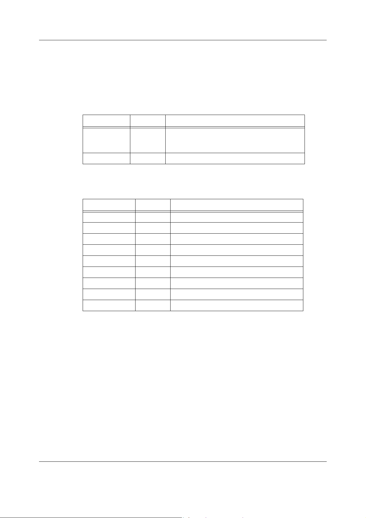
Figure 1 Datex-Ohmeda S/5 Anesthesia Monitor system
(1) 12" LCD display, D-LCC12A
(2) 15” LCD display, D-FPD15
(3) 19" medical grade display
(4) F-CU5P, 5-module frame unit with E-PSM(P) support, and measurement modules
(5) Patient Side Module, E-PSM(P)
(6) F-CPU, central processor unit for F-CU5(P), and N-AC, power unit
(7) F-CU5, 5-module frame unit, and measurement modules
(8) Extension Frame, F-EXT4
(9) Extension Module, E-EXT
(10) F-CU8, 8-module Central Unit, and measurement modules
(11) Detachable Command Bar to be used with displays not having an integrated Command
Bar
(12) Anesthesia record keeping keyboard for automated record keeping
(13) Remote Controller, K-REMCO
(14) Printer
3
Document no. M1137263-04
Page 16
Datex-Ohmeda S/5 Anesthesia and Critical Care Monitors
1.1 Symbols
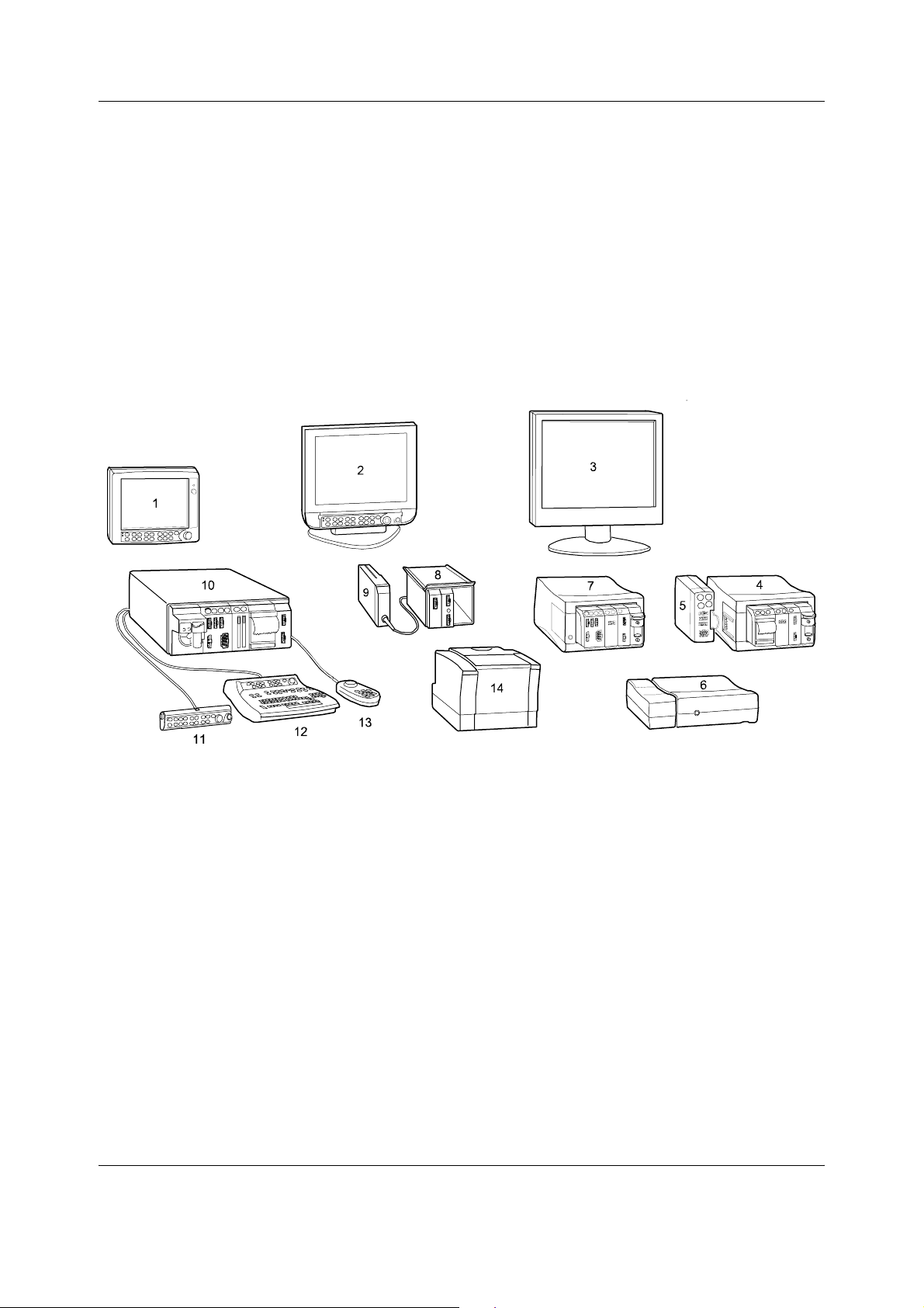
1.1.1 Symbols on transport packaging
The contents of the transport package are fragile and must be handled with
care.
Indicates the correct upright position of the transport package.
The transport package must be kept in a dry environment.
Indicates the temperature limitations within which the transport package
should be stored.
This package can be recycled.
4
Document no. M1137263-04
Page 17
1.1.2 Symbols on equipment
The battery contains lead acid, and in the event of disposal must be separated from
other waste according to local regulations.
Pb
The separate collection symbol is affixed to a battery, or its packaging, to advise
you that the battery must be recycled or disposed of in accordance with local or
country laws. The letters below the separate collection symbol indicate whether
certain elements (Pb=Lead, Cd=Cadmium, Hg=Mercury) are contained in the
Pb/Cd/Hg
battery. To minimize potential effects on the environment and human health, it is
important that all marked batteries that you remove from the product are properly
recycled or disposed. For information on how the battery may be safely removed
from the device, please consult the technical or service manual, or equipment
instructions. Information on the potential effects on the environment and human
health of the substances used in batteries is available at this url:
http://www.gehealthcare.com/euen/weee-recycling/index.html
Introduction
Pb
This battery contains lead and can be recycled.
Dangerous voltage.
When using the ARK Barcode Reader, N-SCAN, do not stare into beam. The N-SCAN
Barcode Reader is a Class 2 laser product.
Document no. M1137263-04
5
Page 18

Datex-Ohmeda S/5 Anesthesia and Critical Care Monitors
1.1.3 Equipment safety symbols
- Attention, consult accompanying documents.
- When displayed next to the O
is set below 21%.
- When displayed next to the HR value, indicates that the pacer is set on R.
- On the modules or frames indicates the following warning:
WARNING Do not use modules with identical measurements in
the same monitor. If such modules have been inserted,
remove the module that has been most recently
connected. You can also remove both modules and
re-connect the new module after five seconds.
- On the 15” Flat Panel Display, D-FPD15-00, indicates the following warning:
WARNING The display must only be used together with the
original type of D-FPD15 power adapter. The display
should be supplied from the mains outlet.
- On the 19” display, D-LCC19, indicates the following warning:
WARNING The display must only be supplied from the mains
outlet via an appropriate additional separating
transformer and the original D-LCC19 power adapter,
not from the Central Unit, F-CU8.
value, indicates that the FiO2 low alarm limit
2
- On the E-PRESTN, E-PRETN, E-RESTN, E-PSM, E-PSMP, E-P, E-PP, E-PT, E-COP
and E-COPSv module indicates the following warning:
WARNING Protection against cardiac defibrillator discharge is
due in part to the accessories for pulse oximetry
(SpO2), temperature (T) and invasive pressure (P)
measurement.
- On the E-NMT module indicates the following warnings:
WARNING Do not place the NMT stimulating electrodes on the
patient’s chest.
WARNING Always stop the NMT measurement before handling
the stimulating electrodes.
WARNING Never subject a patient with an implanted electronic
device to electrical stimulation without consulting a
medical specialist first.
- On the rear or bottom panel this symbol indicates the following warnings
and caution:
WARNING Electric shock hazard. Do not open the cover or the
back. Refer servicing to qualified service personnel.
WARNING Disconnect from the power supply before servicing.
WARNING Do not use the monitor without manufacturer
approved mounting attached.
CAUTION For continued protection against fire hazard, replace the
fuse only with one of the same type and rating.
6
Document no. M1137263-04
Page 19
Introduction
- BIS: On the Aspect DSC indicates the following caution:
CAUTION The converter must not be opened for any reason or
autoclaved.
- On the Interface Module E-INT indicates that it is for connecting external
devices. Do not connect patient cables to the module.
Type BF (IEC 60601-1) protection against electric shock.
Type BF (IEC 60601-1) defibrillator-proof protection against electric shock.
Type CF (IEC 60601-1) protection against electric shock.
Type CF (IEC 60601-1) defibrillator-proof protection against electric shock.
1.1.4 Other symbols
When displayed in the upper left corner of the screen, indicates that the alarms
are silenced. When displayed in the menu or digit fields, indicates that the alarm
source has been turned off or alarm does not meet the alarm-specific activation
criteria.
ESD warning symbol for electrostatic sensitive devices. Pins of connectors
identified with the ESD warning symbol should not be touched. Connections
should not be made to these connectors unless ESD precautionary procedures
are used. For details, see section “1.2.2. ESD precautionary procedures”.
Symbol for non-ionizing electromagnetic radiation. Interference may occur in
the vicinity of equipment marked with this symbol.
Equipotentiality. Monitor can be connected to potential equalization
conductor.
Alternating current
Fuse. Replace the fuse only with one of the same type and rating.
SN, S/N
Serial Number
Connector for color display
7
Document no. M1137263-04
Page 20
Datex-Ohmeda S/5 Anesthesia and Critical Care Monitors
Signal/power output
Signal/power input
Signal/power input/output
Connector for defibrillator synchronization
Connector for the S/5 Device Interfacing Solution, DIS
Power input
Signal input
Power input
Submenu. Selecting an alternative marked with this symbol in a menu opens a
new menu.
The monitor is connected to the Datex-Ohmeda Network (LAN).
Data Card (green) and/or Menu Card (white) is inserted.
Ethernet connector
A blinking heart next to the heart rate or pulse rate value indicates the beats
detected.
8
Document no. M1137263-04
A lung next to the respiration rate value indicates that respiration rate is
calculated from the impedance respiration measurement.
Gas inlet
Page 21
Gas outlet
Do not reuse.
Use by. Indicates the last use day.
Date of manufacturer
Does not contain Latex.
Introduction
Do not immerse the sensor in liquids.
Document no. M1137263-04
9
Page 22
Datex-Ohmeda S/5 Anesthesia and Critical Care Monitors
IPX class:
IPX0
IPX1
IPX2
IPX3
IPX4
IPX7
IPX8
20
Degree of protection against harmful ingress of water as detailed in the
IEC 60529:
- Ordinary equipment
- Protection against vertically falling water drops.
- Protection against vertically falling water drops when enclosure tilted
up to 15 °.
- Protected against spraying water.
- Protected against splashing water.
- Protected against the effects of temporary immersion in water.
- Protected against the effects of continuous immersion in water.
This symbol indicates that the waste of electrical and electronic equipment
must not be disposed as unsorted municipal waste and must be collected
separately. Please contact an authorized representative of the manufacturer
for information concerning the decommissioning of your equipment.
This symbol indicates the product contains hazardous materials in excess of
the limits established by the Chinese standard SJ/T11364-2006 Requirements
for Concentration Limits for Certain Hazardous Substances in Electronic
Information Products. The number in the symbols is the Environment-friendly
Use Period (EFUP), which indicates the period during which the toxic or
hazardous substances or elements contained in electronic information
products will not leak or mutate under normal conditions so that the use of
such electronic information products will not result in any severe
environmental pollution, any bodily injury or damage to any assets. The unit of
the period is “Year”.
In order to maintain the declared EFUP, the product shall be operated normally
according to the instructions and environmental conditions as defined in the
product manual, and the periodic maintenance schedules specified in Product
Maintenance Procedures shall be followed strictly.
Consumables or certain parts may have their own label with an EFUP value
less than the product. Periodic replacement of those consumables or parts to
maintain the declared EFUP shall be done in accordance with the Product
Maintenance Procedures.
This product must not be disposed of as unsorted municipal waste, and must
be collected separately and handled properly after decommissioning.
10
Document no. M1137263-04
Page 23

Introduction
1.2 Safety
The following list contains general warnings and cautions you should know before installing,
maintaining or servicing the system. Warnings and cautions specific to the use of the system
can be found in the User’s Guide and User’s Reference Manual.
1.2.1 Safety precautions Warnings
WARNING A WARNING indicates a situation in which the user or the patient may be in
danger of injury or death.
• The device is not able to withstand unpacked drops from a height of 1 m without
damaging the module latches. If the device is dropped, please service the device before
taking it back into use.
Power connection
• Always check that the power cord and plug are intact and undamaged.
• Do not use the power cord delivered with this product for any other product or purpose.
• Use only hospital-grade grounded power outlets and power cord. Do not remove the
grounding pin from the power plug.
• Use only an intact power cord. Replace the power cord if it is cracked, frayed, broken or
otherwise damaged.
• Do not apply tension to the power cord otherwise the cord may get damaged.
• Do not use an additional multiple socket outlet, extension cord or adapters of any kind.
• Before starting to use the system, ensure that the whole combination complies with the
international standard IEC 60601-1-1 and with the requirements of the local authorities.
Do not connect any external devices to the system other than those specified.
• When detaching Patient Side modules, be careful not to drop them. Always support with
one hand while pulling out with the other.
• To avoid the risk of electric shock, this equipment must only be connected to a supply
mains with protective earth.
Installation
• Keep the monitor horizontal when the Compact Airway Module is used. T ilting the
monitor may cause erroneous results in the Compact Airway Module’s readings and
damage the module.
• The monitor or its components should not be used adjacent to or stacked with other
equipment. If adjacent or stacked use is necessary, the monitor and its components
should be observed to verify normal operation in the configuration in which it will be
used.
• Pins of connectors identified with the ESD warning symbol should not be touched.
Connections should not be made to these connectors unless ESD precautionary
procedures are used. For details, see section “1.2.2. ESD precautionary procedures”
• After transferring or reinstalling the monitor, always check that it is properly connected and
all parts are securely attached. Pay special attention to this in case of stacked mounting.
• Do not use the monitor in high electromagnetic fields (for example, during MRI.)
• Never install the monitor or the displays so that they are above the patient.
Document no. M1137263-04
11
Page 24

Datex-Ohmeda S/5 Anesthesia and Critical Care Monitors
• A secondary display and printer must always be supplied from an additional transformer
providing at least basic isolation (isolating or separating transformer.) Without an
appropriate transformer the leakage current of the secondary display can be too high.
• A printer or computer must be supplied from an additional transformer providing at least
basic isolation (isolating or separating transformer).
• If you accidentally drop the monitor, modules or frames, have them checked by
authorized service personnel prior to clinical use.
• To avoid explosion hazard, do not use the monitor in presence of flammable anesthetics.
The monitor measures only non-flammable anesthetics.
• Do not touch the patient, table, instruments, modules or the monitor during defibrillation.
Laser radiation
• When using the ARK Barcode Reader, N-SCAN, do not stare into the beam. The N-SCAN is
a Class 2 laser product.
External connection
• Do not connect any external devices to the monitor other than those specified.
Explosion hazard
• To avoid explosion hazard do not use the monitor in the presence of flammable
anesthetics.
Patient safety
• Do not perform any testing or maintenance on the monitor while it is being used on a
patient.
• PACEMAKER PATIENTS: The impedance respiration measurement may cause rate
changes in Minute Ventilation Rate Responsive Pacemakers. In this case, set the
pacemaker rate responsive mode off or turn the monitor impedance respiration
measurement off.
• Never install the monitor or the displays so that they are above the patient.
• The monitor must not be used without manufacturer approved mounting attached.
• Operation of the monitor outside the specified values may cause inaccurate results.
Autoclaving and sterilizing
• Do not autoclave any part of the system with steam or sterilize with ethylene oxide.
Cleaning and service
• Only trained personnel with proper tools and test equipment should perform the tests
and repairs described in this manual. Unauthorized service may void the monitor
warranty.
• Always unplug the monitor before cleaning or service. After cleaning or service ensure
that every part of the monitor is dry before reconnecting it to the power supply.
• Do not touch any exposed wire or conductive surface while any cover is removed and the
monitor is energized. The voltages present can cause injury or death.
• Pins of connectors identified with the ESD warning symbol should not be touched.
Connections should not be made to these connectors unless ESD precautionary
procedures are used. For details, see section “1.2.2. ESD precautionary procedures”.
12
Document no. M1137263-04
Page 25

Introduction
• Electrostatic discharge through the PC boards may damage the components. Before
handling PC boards, wear a static control wrist strap. Handle all PC boards by their
non-conductive edges and use anti-static containers when transporting them.Do not
break or bypass the patient isolation barrier when testing PC boards.
• Always perform an electrical safety check and a leakage current test on the monitor after
service.
• Handle the water trap and its contents as you would any body fluid. Infectous hazard
may be present.
• Do not immerse any part of the device in any liquid, or allow liquid to enter the monitor or
modules.
• If liquid has accidentally entered the system or its parts, disconnect the power cord from
the power supply and have the equipment serviced by authorized service personnel.
• Since calibration gas contains anesthetic agents, always ensure sufficient ventilation of
the room during calibration.
Accessories
• Use only accessories, including mounts and batteries, and defibrillator-proof cables and
invasive pressure transducers approved by GE Healthcare. For a list of approved supplies
and accessories, see the “Supplies and Accessories” catalog delivered with the monitor.
Other cables, batteries, transducers and accessories may cause a safety hazard, damage
the equipment or the system, result in increased emissions or decreased immunity of the
equipment or system or interfere with the measurement. Protection against cardiac
defibrillator discharge is due in part to the accessories for pulse oximetry (SpO2),
temperature (T) and invasive pressure (P) measurement.
• Single use accessories are not designed to be reused. Reuse may cause a risk of
contamination and/or affect the measurement accuracy.
Special components
Special components are used in these monitors that are vital to assure reliability and safety. GE
Healthcare assumes no responsibility for damage, if replacement components not approved
by GE Healthcare are used.
Batteries
The battery packages in the central unit, F-CPU and in the power supply unit of F-CU8 contain
lead acid (Pb) which is hazardous to the environment and therefore needs to be disposed of
carefully according to local regulations.
Refresh the batteries completely every six months.
To replace the batteries safely, please refer to the service instructions in this manual.
• Do not short-circuit the battery terminals, this may produce a very high current, which will
damage the battery.
• Do not dispose of the battery into open flame, nor put the battery near fire, as it may
explode.
• Do not dismantle the battery. It contains electrolyte, which may damage clothing or
cause injury to skin or eyes. If exposed to electrolyte, wash the injured area with plenty of
clean water and contact a doctor.
See also section “Symbols”.
13
Document no. M1137263-04
Page 26

Datex-Ohmeda S/5 Anesthesia and Critical Care Monitors
Cautions
CAUTION A CAUTION indicates a condition that may lead to equipment damage or
malfunction.
Installation
• Leave space for air circulation to prevent the monitor from overheating.
• Ensure that the module is properly orientated (i.e. module release latch facing downward)
before insertion.
• Before connecting the power cord to the power supply, check that the local voltage and
frequency correspond with the rating stated on the device plate. See instructions for
different displays in section “Displays”.
• Turn off the power before making any rear panel connections.
Before use
• Allow two minutes for warm-up and note any error messages or deviations from normal
operation.
• Clean the rear panel fan dust filters once a month or whenever necessary.
• Do not connect a sampling line to the female Patient Spirometry connector while the
other end of the sampling line is connected to the D-fend water trap. The pressure in the
gas sampling system may cause damage to the PVX unit pressure transducers.
Fuse replacement
• Replace a fuse only with one of the same type and rating.
Cleaning and service
• Do not use hypochlorite-, acetone-, phenol- or ammonia -based cleaners, abrasive
material or harsh chemicals as they may damage the surfaces of the device.
• Do not use abrasive cleaning compounds, instruments, brushes or rough-surface
materials.
• Do not apply pressurized air to any outlet or tubing connected to the monitor. Pressure
may destroy sensitive elements.
• Do not clean the spirometry tubes with high pressure air or O
spirometry tubes are connected to Patient Spirometry connector. High differential
pressure may damage PVX unit pressure transducers.
flushing while the
2
Special components
• A lithium battery on the CPU Board. Dispose of the faulty IC containing the battery
according to local regulations.
Storage and transport
Do not store or transport the monitor outside the specified temperature, pressure and humidity
ranges:
Temperature -10...+50 °C/14...122 °F
Atmospheric pressure 660...1060 hPa/500...800 mmHg/660...1060 mbar
Relative humidity 10...90% noncondensing
For display specific environmental requirements see specifications in the “Display” slot.
14
Document no. M1137263-04
Page 27

1.2.2 ESD precautionary procedures
To avoid electrostatic charges building up, it is recommended to store, maintain and use
•
the equipment at a relative humidity of 30% or greater. Floors should be covered by ESD
dissipative carpets or similar. Non-synthetic clothing should be used when working with
the component.
• To prevent applying a possible electrostatic discharge to the ESD sensitive parts of the
equipment, one should touch the metallic frame of the component or a large metal object
located close to the equipment. When working with the equipment and specifically when
the ESD sensitive parts of the equipment may be touched, a grounded wrist strap
intended for use with ESD sensitive equipment should be worn. Refer to the
documentation provided with the wrist straps for details of proper use.
ESD precautionary procedure training
It is recommended that all potential users receive an explanation of the ESD warning symbol
and training in ESD precautionary procedures.
The minimum contents of an ESD precautionary procedure training should include an
introduction to the physics of electrostatic charge, the voltage levels that can occur in normal
practice and the damage that can be done to electronic components if they are touched by an
operator who is electrostatically charged. Further, an explanation should be given of methods
to prevent build-up of electrostatic charge and how and why to discharge one’s body to earth
or to the frame of the equipment or bond oneself by means of a wrist strap to the equipment or
the earth prior to making a connection.
Introduction
1.2.3 Disposal
Dispose of the whole device, parts of it and its packing material and manuals in accordance
with local environmental and waste disposal regulations.
15
Document no. M1137263-04
Page 28

Datex-Ohmeda S/5 Anesthesia and Critical Care Monitors
16
Document no. M1137263-04
Page 29
2 System description
2.1 Introduction
Datex-Ohmeda monitors build up a freely configurable modular system. The architecture is
designed to enable different module combinations so that the user is able to get the desirable
parameter and feature set. This modular approach makes it possible to add new features
when they are needed.
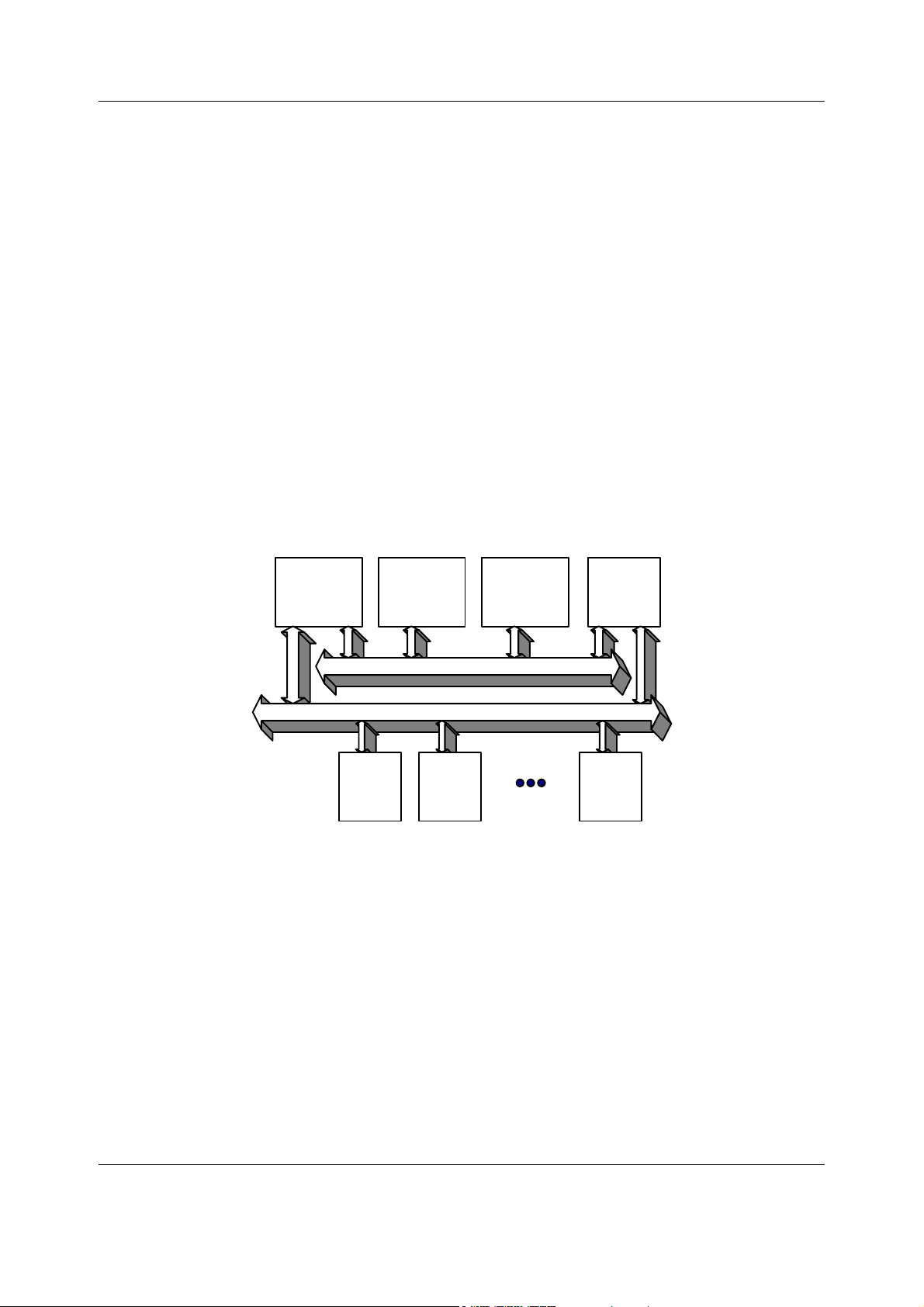
2.2 Bus structure
The operation of Datex-Ohmeda monitors is based on two communication channels, the CPU
bus and module bus.
In the 5-Module Central Unit, PC boards receive power from the F-CPU power supply and the
parameter modules receive power from a separate power supply in the 5-Module Frame unit.
These power supplies are both fed by the N-AC Power Unit. In the 8-Module Central Unit, F-CU8,
all PC boards connected to the CPU bus, as well as the parameter modules attached to the
module bus receive power from the same power supply, which is an integral part of the Central
Unit, F-CU8.
System description
UPI CPU
Parameter
Module
CPU Bus
Module Bus
Parameter
Module
Display
Controller
Power
Supply
Unit
Parameter
Module
Figure 2 General bus structure of S/5 system
The CPU bus is a communication channel used only for internal data transfer. It is based on the
ISA bus used in IBM PC computers. Data is transferred on this 16 bit wide bus using the CPU
clock frequency.
The module bus is used to connect the parameter modules to the Central Unit. The bus is based
on the industry standard RS-485, which uses a differential serial method to transfer data. This
type of bus is robust and it allows parameter modules to be inserted or removed while the
power is on. The module bus uses a 500 kbps data transfer rate and can be used for longer
distances than the CPU bus, e.g. for external frame connections.
The RS-485 type of serial communication supports so-called multidrop or party line
connections. This means that all parameter modules connected to the module bus use exactly
the same lines for communication. The advantage of this is that all bus connectors are
identical and the modules can be connected in any order and position.
17
Document no. M1137263-04
Page 30
Datex-Ohmeda S/5 Anesthesia and Critical Care Monitors
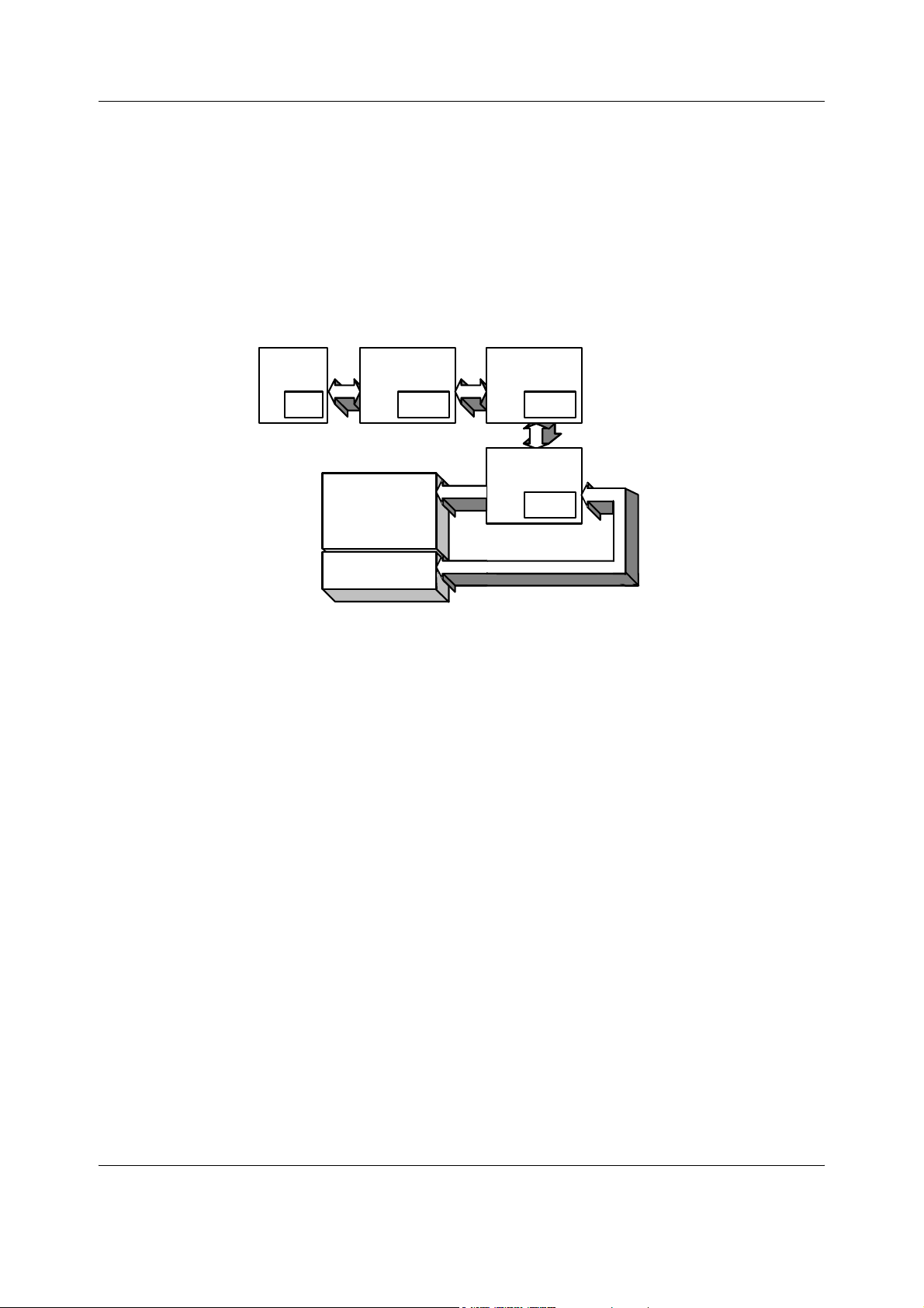
2.3 Distributed processing
A system assembled from Datex-Ohmeda products is a multiprocessor system. All parameter
modules have their own microprocessor, which performs functions such as module key
control, waveform filtering, parameter related computing and pneumatic control, etc. At the
same time the main CPU performs higher level tasks such as trending and alarm control. While
the parameter modules and CPU are performing their tasks, the UPI (Universal Peripheral
Interface) microprocessor handles all functions needed to transfer data between the
parameter modules and the CPU. At the same time the Display controller microprocessor
performs pixel calculations for graphics.
Module
RAM
Display
Command
Board/Bar
UPI
Dual-port
RAM
Figure 3 Distributed processing in S/5 system
This kind of parallel processing gives one major advantage to centralized processing. When
new parameter modules or PC boards are added to the system, the processing power is
increased. As a result, the system does not slow down when new features are added.
2.4 Module communication
The communication master controlling data transfers between the CPU and parameter
modules is called UPI processor. It sends data to each connected module 100 times a second.
Modules respond to each data request immediately by sending a data package, whose length
depends on the type of the module. This communication protocol ensures that each module
receives and sends data every 10 ms. If a module does not respond to data requests, the UPI
processor presumes that the module is disconnected.
Parameter modules may hold a static (fixed) or dynamic address, which the UPI processor uses
when sending out data. Two parameter modules of the same type must not be fitted onto the
same monitor since they might reply to a data request simultaneously, thus causing
communication errors.
CPU
Display
Controller
System
memory
Display
memory
18
Document no. M1137263-04
Page 31

System description
UPI Board
CPU Bus
Dual-port
RAM
Module Bus
Microcontroller
Figure 4 Principle of UPI section operation
The UPI processor collects and stores all data that is received from the parameter modules into
a dual port RAM, which is mapped directly to the address space of the main CPU. The main CPU
reads data from the memory while the UPI processor guarantees that the data is up to date.
This operation also works in the other direction. In this the main CPU fills the dual port RAM with
data and the UPI processor distributes it to the parameter modules.
2.5 Software loading
The program memory on the CPU board is loaded with monitor software at the factory. The
software is used for running all the functions that are integrated into the PC board. For service
and upgrade procedures,the B-CPU6 board is equipped with Ethernet LAN port through which
new software can be loaded.
UPI
Board
Program
Memory
CPU
Board
Service
Software
Ethernet
Flash
Program
Memory
CPU Bus
LAN
Display
Controller
Board
Program
Memory
Softwareloading_cpu6.vsd
Figure 5 Software loading
19
Document no. M1137263-04
Page 32

Datex-Ohmeda S/5 Anesthesia and Critical Care Monitors
2.6 Parameter modules
RAM
EEPROM
+5 V
±12 V
CPU
Isolation
transformer
Patient isolation
Opto
isolation
RS485
drivers
+15 V
Reset
Data
Module Bus
Patient
ke
Module
ke
keys
ys
ys
Analog
electronics
Peripheral
drivers
A/D
converter
Figure 6 General structure of parameter modules with patient isolation
The detailed structure of a parameter module depends on the specific needs for each
individual parameter. However, some common parts are used in the parameter modules. The
electronics inside the module is usually divided into isolated (floating) and non-isolated
sections. Typically, the non-isolated section consists of buffers to interface the parameter
module to the module bus while the rest of the electronics is located in the isolated section. The
isolated section includes the microcontroller together with memory components, the front-end
analog electronics (amplifiers, etc.) and sensor drivers.
20
Document no. M1137263-04
Page 33

3 System installation
3.1 Unpacking instructions
1. Confirm that the packing box is undamaged. If the box is damaged, contact the shipper.
2. Open the top of the box and carefully unpack all components.
3. Confirm that all components are undamaged. If any of the components are damaged,
contact the shipper.
4. Confirm that all components are included. If any of the components are missing, contact
your GE Healthcare distributor.
3.2 Choosing location
Consider the following aspects:
• lighting
• space
• connections
System installation
• electromagnetic and radio frequency interference, see Appendix B. ElectroMagnetic
Compatibility
• environment
The F-CU8 should be placed so that liquid is prevented from entering the casing.
WARNING The monitor or its components should not be used adjacent to or stacked
with other equipment. If adjacent or stacked use is necessary, the monitor
and its components should be observed to verify normal operation in the
configuration in which it will be used.
CAUTION The monitor display is fragile. Ensure that it is not placed near a heat source or
exposed to mechanical shocks, pressure, moisture, or direct sunlight.
21
Document no. M1137263-04
Page 34

Datex-Ohmeda S/5 Anesthesia and Critical Care Monitors
3.3 Central Unit; S/5 8-Module Frame, F-CU8
8_module_frame.vsd
Figure 7 Central Unit: S/5 8-Module Frame, F-CU8
The front of the Central Unit, F-CU8, houses plug-in parameter modules which interface the
system with external devices. The back of the Central Unit houses the system circuit boards,
together with expansion slots which accommodate PC boards which interface with external
devices and the Datex-Ohmeda Network.
3.3.1 Connecting to mains
Connect the power cord to the mains power inlet on the rear of the Central Unit and to the wall
socket.
WARNING The power cord may only be connected to a three-wire, grounded, hospital
grade receptacle.
3.3.2 Connecting to the Datex-Ohmeda Network
To connect the monitor to the Datex-Ohmeda Network, make sure a CPU Board, B-CPU6 is
installed.
Use the Monitor-Network cable to connect the monitor to the network as follows:
1. Make sure that the power to the Central Unit is turned off.
2. Connect the RJ-45 network connector to the connector X10 on the CPU board, B-CPU6
and the Identification Plug to the corresponding connector on the B-UPI4NET.
3. Connect the other RJ-45 connector to the corresponding connector on the wall box.
4. Turn on the power to the Central Unit. Enter the Network service menu:
Monitor Setup - Install/Service (password 16-4-34) Service (password 26-23-8) -
Frame – Network
5. Make sure that the monitor's network communication has been set according to the used
network software:
Network software S-CNET01 -> DRI Level = 2001
Network software S-CNET02 -> DRI Level = 2001
Network software L-NET03 -> DRI Level = 2003
Network software L-NET05 -> DRI Level = 2005
If necessary, change the monitor's network communication by selecting DRI Level and
turning the ComWheel.
NOTE: If the DRI level is changed, the monitor will restart automatically.
22
Document no. M1137263-04
Page 35

6. Confirm that the network symbol and ‘Connected to Network’ message are displayed on
the upper part of the screen.
3.3.3 Inserting the parameter modules
1. Ensure that the module is properly orientated (i.e. module release latch facing downward).
2. Align the module insertion guide slot with the frame insertion guide.
3. Push the module into the frame until it clicks.
System installation
Figure 8 Module insert
NOTE: The Compact Airway Modules cannot be placed into the third and fourth slot from the
right-hand side of the F-CU8 Central Unit.
NOTE: Use only one Extension Frame F-EXT4 in one F-CU8 Central Unit.
NOTE: Do not use two or more parameter modules with identical functions in the monitor
system. Take special care not to do this when using the Extension Frame, F-EXT4.
• Hemodynamic multiparameter modules, E-PRESTN, E-PRETN, E-RESTN, E-PSM, E-PSMP,
M-PRESTN, M-PRETN, M-RESTN, M-ESTPR, M-ETPR, M-ESTR, M-NESTPR, M-NETPR,
M-NESTR, M-NE12STPR, M-NE12TPR, M-NE12STR
• Dual Pressure Modules, E-PP/M-PP
• Pressure Modules, E-P/ M-P, Pressure Temp Module, E-PT/ M-PT
• Cardiac Output Modules, E-COP, E-COPSv, M-COP and M-COPSv
• NIBP Modules, M-NIBP and hemodynamic modules w/ N measurement
• Airway Modules, E-CO, E-COV, E-COVX, E-CAiOVX, E-CAiOV, E-CAiO, E-miniC, M-C, M-CO,
M-COV, M-CAiO, M-CAiOV, M-CAiOVX, G-O, G-OV, G-AO, G-AiO, G-AOV, G-AiOV, M-MiniC
• Interface Module, E-INT / M-INT and Interface Board, B-INT
• Oxygen Saturation Modules, E-MASIMO, E-NSATX/ E-NSAT/ M-NSAT and M-OSAT
• Tonometry Modules, E-TONO/ M-TONO
• NeuroMuscular Transmission Modules, E-NMT/ M-NMT
• EEG Modules, E-EEG/ M-EEG
• BIS Modules, E-BIS/ M-BIS
23
Document no. M1137263-04
Page 36

Datex-Ohmeda S/5 Anesthesia and Critical Care Monitors
3.3.4 E-PSM(P) Mounting Accessories
Intended use
The Frame Mount for PSM and the Pole Mount for PSM, short and long, are intended to be used
with the stationary docking station of the E-PSM(P) module. The Interface Module for PSM,
E-INTPSM, is intended for connecting the Frame Mount and the Pole Mount to the
Datex-Ohmeda S/5 F-CU8.
The Module Bus Adapter for PSM is intended for connecting the Pole Mount for PSM to the
Datex-Ohmeda S/5 F-CU5 frame.
The Frame Mount for PSM can be attached directly to the F-CU8. The Pole Mount for PSM, short
or long, can be attached to an IV pole or to an anesthesia machine rail with a diameter of
10mm* 25mm.
With Interface Module for PSM, E-INTPSM, the Frame Mount or the Pole Mount can be
connected to the Datex-Ohmeda S/5 F-CU8 frame equipped with software license 04 or later.
The E-PSM(P) module can be attached to the Frame Mount or Pole Mount and used like a
Datex-Ohmeda S/5 modular module.
With Module Bus Adapter, the Pole Mount for PSM, short or long, can be connected to the
Datex-Ohmeda S/5 F-CU5 frame. The E-PSM(P) module can be removed from the F-CU5 frame
and docked to the Pole Mount for PSM, short or long.
1
2
3
4
5
Figure 9 E-PSM(P) mounting accessories
1. M1054424 Interface Module for PSM, E-INTPSM
2. M1051025 Module Bus Adapter for PSM
3. M1051021 Frame Mount for PSM
4. M1049197 Pole Mount for PSM, short
5. M1051023 Pole Mount for PSM, long
24
Document no. M1137263-04
Page 37

System installation
Frame mount for PSM - Instructions for connecting to the F-CU8 frame
MARK
BOTTOM
FRONT
1. The correct drilling locations are marked through the
marking holes on the enclosed plate.
2. Set front and bottom of the plate as shown in the picture.
3. The texts MARK, BOTTOM and FRONT are carved on the
plate to help you locate the correct locations.
4. Drill the holes, drill diameter 5mm/0.197 in.
5. Assemble the PSM frame, screws and the plate on the
opposite side of the frame wall and tighten the screws.
6. Insert the E-INTPSM module and connect the cable.
Attach the E-PSM(P) module and check the module
communication.
WARNING Make sure that the Pole Mount for PSM is always used in vertical position to
prevent water from entering the E-PSM(P) module.
Pole Mount for PSM – Instructions for connecting to an IV pole, vertical
position
Fasten the Pole Mount for PSM
with the fastening screw of the
clamp and tighten properly to an
IV pole.
Pole Mount for PSM - Instructions for installing in horizontal position.
Remove the 2 screws from the clamp, turn the clamp and insert and tighten the screws back.
Fasten the Pole Mount for PSM with the fastening screw of the clamp and tighten properly to a
horizontal tube or rail with a diameter of 10 mm*25 mm.
25
Document no. M1137263-04
Page 38
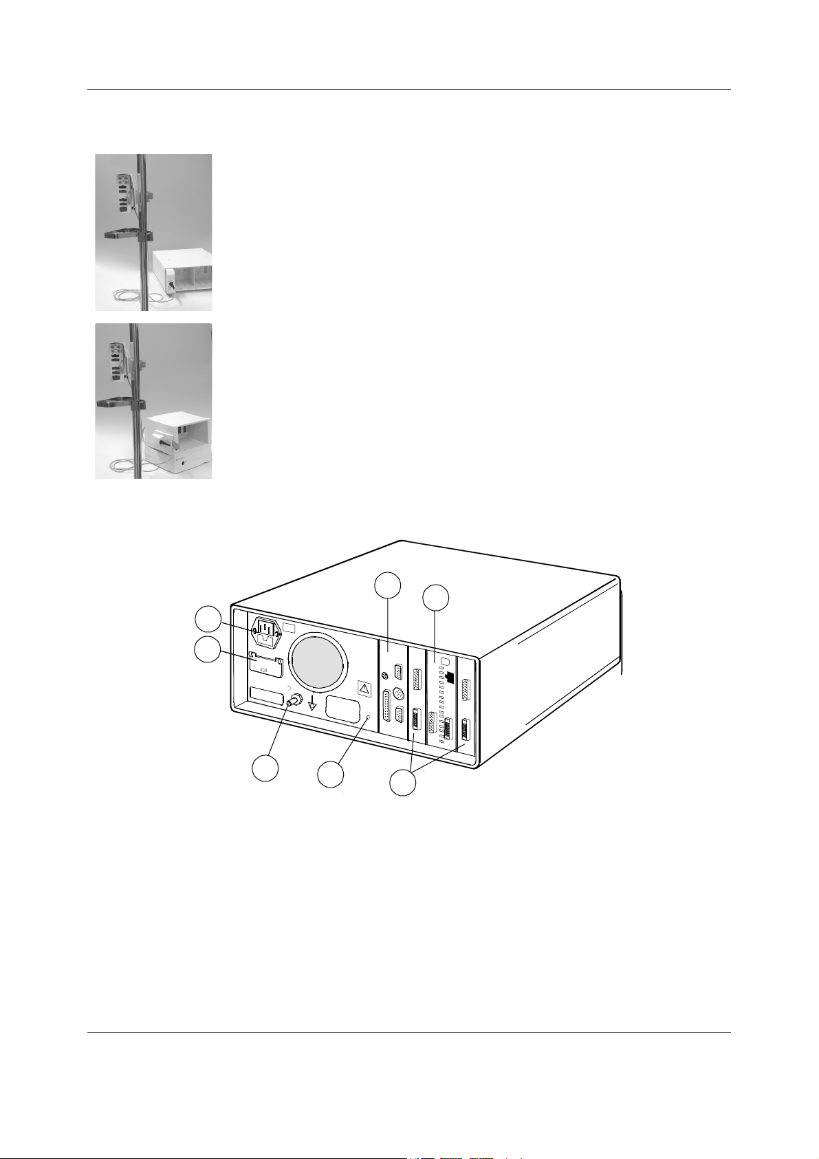
Datex-Ohmeda S/5 Anesthesia and Critical Care Monitors
Pole mount for PSM – Instructions for connecting to frame
1. Attach the E-PSM(P) module to the Pole Mount.
2. Connect the cable of the Pole Mount for PSM to the F-CU8
with the E-INTPSM module (M1054424).
3. Check the module communication of the E-PSM(P)
module.
1. Attach the E-PSM(P) module to the Pole Mount.
2. Connect the cable of the Pole Mount for PSM to the S/5
F-CU5 with the Module Bus adapter for PSM (M1031025).
3. Check the module communication of the E-PSM(P)
module.
3.3.5 Positioning PC boards
1
1
2
2
9
7
Figure 10 Rear view and positioning, F-CU8 (-12 shown)
(1) Mains power inlet
(2) Battery 24 Vde input connector (F-CU8 - 12) / Display power outlet (F-CU8 rev. 03 to 09)
(3) UPINET Board, B-UPI4NET
(4) B-CPU6 and integrated display controller (primary/screen1)
(5) Display Controller Board, B-DISPX (secondary/screen 2)
Display Controller Board, B-DISPX (3
(6) Service reset button
(7) Equipotential connector
3
4
3
4
5
6
!
7
6
8
5
rd
screen), Keyboard Interface Board, B-ARK
26
Document no. M1137263-04
Page 39

NOTE: Authorized personnel only may open the cover of 24Vdc input connector (use a flat
screwdriver).
3.3.6 Replacing PC boards
For service procedures refer to Part II.
1. Make sure that the power of the monitor is turned off and unplug the power cord. Press
and hold the service reset button on the rear panel for at least five seconds or until an
audible tone is heard (see Figure 11).
System installation
!
Figure 11 Service reset button
2. Remove all PC boards, cover plates and EMC plates on the right-hand side of the PC
board, to be replaced, then remove the board itself (two or four screws).
NOTE: The B-UPI4NET may have been installed so that it can be removed without removing the
other PC boards first.
WARNING The circuit boards contain sensitive integrated circuits that can be
damaged by an electrostatic discharge. Careful handling of the boards is
therefore essential.
NOTE: The B-UPI4NET contains components on both sides of the PCB. Therefore, the installation
of B-UPI4NET should be handled with extra care. Detach the board from the frame carefully by
pulling it from the X3 connector (25 pin female D-connector).
3. Remove the new PC board from the protective antistatic packaging. Always hold the
board by the edges and wear a wrist-grounding strap.
4. Insert the new PC board into the vacant slot and firmly press the board into position.
Secure the board (two or four screws).
5. Insert all other circuit boards, cover plates and EMC plates.
6. Reconnect the power cord.
27
Document no. M1137263-04
Page 40

Datex-Ohmeda S/5 Anesthesia and Critical Care Monitors
3.3.7 Performing Factory Reset
NOTE: The factory reset is necessary after downloading of monitor software and after
replacing the CPU board or SRAM/Timekeeper battery.
NOTE: A factory reset will restore all customized defaults, including language selection, to
factory defaults.
1. Press the
2. Select Install/Service and password (16-4-34).
3. Select Service and password (26-23-8).
4. Select Set/Test and perform a Factory Reset.
5. The monitor will perform an automatic restart. After the restart is completed, restart the
monitor also manually by the On/Standby switch.
Monitor Setup key.
3.4 Central Unit; S/5 5-Module Frame, F-CU5
The central unit is divided into three parts: the 5-Module Frame F-CU5(P), the Central Processor
Unit F-CPU and the universal power unit N-AC.
The 5-Module Frame has two options, a frame (F-CU5P) that allows connection to an E-PSM(P)
module, and a frame (F-CU5) that cannot be connected to an E-PSM(P) module.
F-CU5 provides places for up to five single-width modules or two double-width modules (plus
one slot for one single-width module) and in F-CU5P a connector plate for E-PSM or E-PSMP.
The Central Processor Unit houses the system circuit boards.
NOTE: You can connect two F-CU5(P) 5-Module Frames to one F-CPU. If you do so, you cannot
at the same time use a display that uses B-DISPX as a power supply (for example 12" LCD
display).
WARNING After transferring or reinstalling the monitor, always check that it is
properly connected and all parts are securely attached. Pay special
attention to this in case of stacked mounting.
28
Document no. M1137263-04
Page 41

F-CU5(P)
System installation
F-CPU signal cable
N-AC
F-CPU
Figure 12 F-CU5 parts connected with cables
F-CPU power cable
Power cord
Figure 13 Two F-CU5s connected to one F-CPU
3.4.1 Mounting the Frame
The various mount options and connecting cables allow you to install the F-CU5(P) 5-Module
Frame, F-CPU Central Processor Unit and N-AC Power Unit either in one package or separately.
You can, for example, attach the Central Processor Unit and Power Unit to the wall or table leg
and have the Central Unit at hand.
There are different interconnecting cable options available:
F-CPU Power Cable 0.4 m/16 inch and 2.7 m /9 ft
F-CPU Signal Cable 0.3 m/12 inch, 3m/10 ft and 10m/33 ft
29
Document no. M1137263-04
Page 42
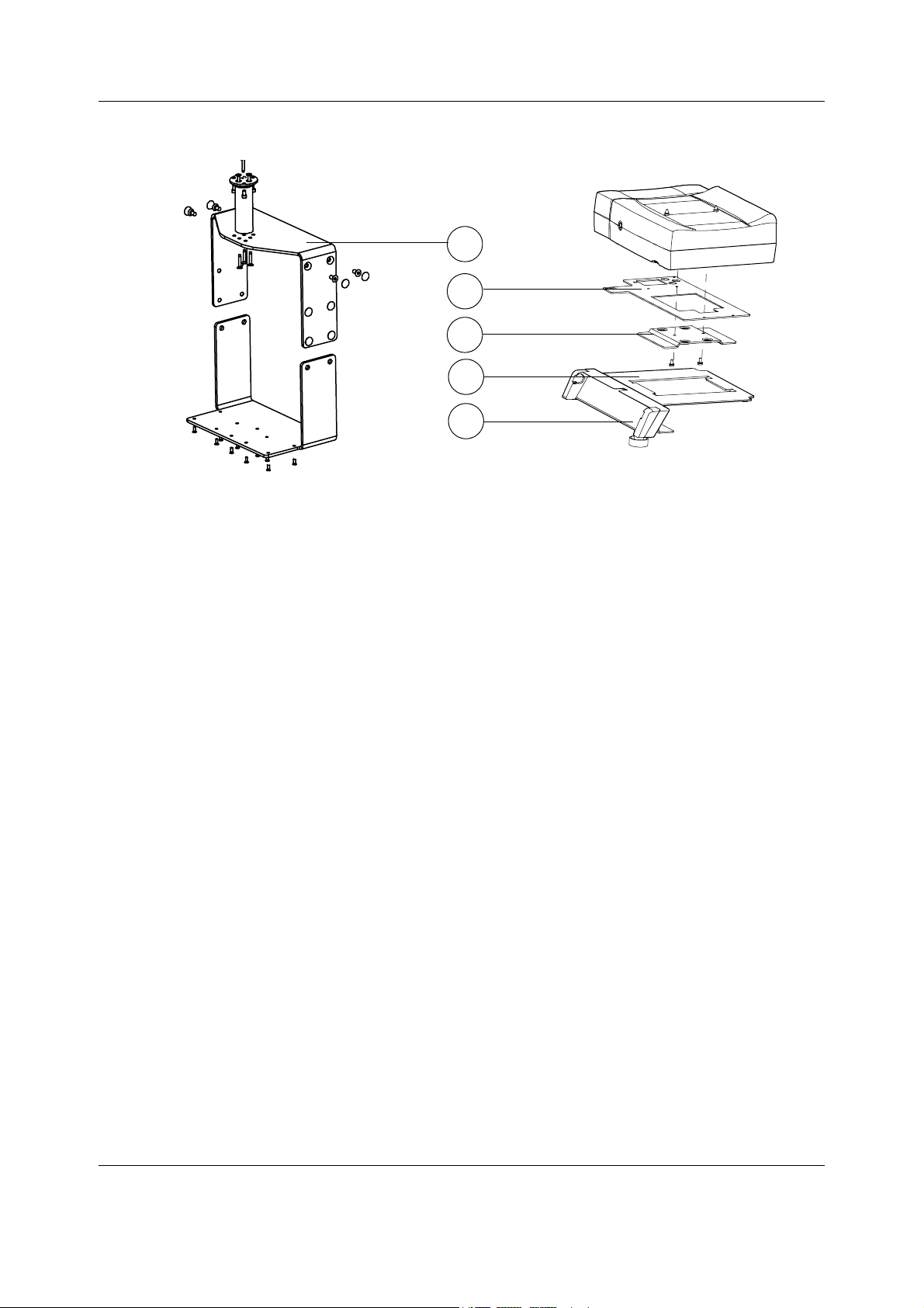
Datex-Ohmeda S/5 Anesthesia and Critical Care Monitors
The different mounts to install the Central Unit F-CU5
(1) Wall Mount Hanger for S/5 F-CU5
(2) Power Adapter Mount for F-CU5 Power Unit N-AC
(3) Adapter Plate for S/5 F-CU5
(4) Table Holder for S/5 F-CU5
(5) Holder for S/5 Command Bar
1
2
3
4
5
3.4.2 Connecting to mains
Make sure the cables connecting the different units together are connected and secured.
Connect the power cord to the mains power inlet on the N-AC power unit, and to the wall socket.
WARNING The power cord may only be connected to a three-wire, grounded, hospital
grade receptacle.
3.4.3 Connecting to the Datex-Ohmeda Network
To connect the monitor to the Datex-Ohmeda Network, make sure a Network Board B-UPI4NET
is installed.
Use the Monitor-Network cable to connect the monitor to the network as follows:
1. Make sure that the power to the Central Unit is turned off.
2. Connect the RJ-45 network connector to the X10 connector on CPU board, B-CPU6 and
the Identification Plug to the corresponding connector on the B-UPI4NET.
3. Connect the other RJ-45 connector to the corresponding connector on the wall box.
4. Turn on the power to the Central Unit. Enter the Network service menu:
Install/Service (password 16-4-34) - Service (password 26-23-8) - Frame – Network
5. Make sure that the monitor's network communication has been set according to the used
network software:
Network software S-CNET01 -> DRI Level = 2001
Network software S-CNET02 -> DRI Level = 2001
Network software L-NET03 -> DRI Level = 2003
Network software L-NET05 -> DRI Level = 2005
Monitor Setup -
30
Document no. M1137263-04
Page 43

If necessary, change the monitor's network communication by selecting DRI Level and
turning the ComWheel.
NOTE: If the DRI level is changed, the monitor will restart automatically.
6. Confirm that the network symbol and 'Connected to Network' message are displayed on
the upper part of the screen.
3.4.4 Inserting the parameter modules
1. Ensure that the module is properly orientated (i.e. module release latch facing downward).
2. Align the module insertion guide slot with the frame insertion guide.
3. Push the module into the frame until it clicks.
System installation
NOTE: Do not use two or more parameter modules with identical functions in the monitor
system. Take special care not to do this when using two F-CU5(P) module frames.
Inserting PSM modules
1. Align the module with the insertion guides.
2. Push the module into the monitor frame until it stops.
3. Pull the module outwards. Make sure not to drop it when it comes out.
31
Document no. M1137263-04
Page 44

Datex-Ohmeda S/5 Anesthesia and Critical Care Monitors
WARNING When detaching modules, be careful not to drop them. Always support with
one hand while pulling out with the other.
WARNING Do not use modules with identical measurements in the same monitor. If
such modules have been inserted, remove the module that has been most
recently connected. You can also remove both modules and re-connect the
new module after five seconds.
NOTE: For mounting E-PSM(P) see also 3.3.4. E-PSM(P) Mounting Accessories.
Parameter modules or boards with identical functions are:
• Hemodynamic multiparameter modules, E-PRESTN, E-PRETN, E-RESTN, E-PSM, E-PSMP,
M-PRESTN, M-PRETN, M-RESTN M-ESTPR, M-ETPR, M-ESTR, M-NESTPR, M-NETPR, M-NESTR,
M-NE12STPR, M-NE12TPR, M-NE12STR
• Dual Pressure Modules, E-PP/ M-PP
• Pressure Modules, E-P/ M-P, Pressure Temp Module, E-PT/ M-PT
• Cardiac Output Modules, E-COP, E-COPS, M-COP and M-COPSv
• NIBP Modules, M-NIBP and hemodynamic modules w/ N measurement
• Airway Modules, E-CO, E-COV, E-COVX, E-CAiOVX, E-CAiOV, E-CAiO, E-miniC, M-C, M-CO,
M-COV, M-CAiO, M-CAiOV, M-CAiOVX, M-MiniC
• Interface Module, M-INT and Interface Board, B-INT
• Oxygen Saturation Modules, E-MASIMO, E-NSATX/ E-NSAT, M-NSAT and M-OSAT
• Tonometry Modules, E-TONO/ M-TONO
• NeuroMuscular Transmission Modules, E-NMT/ M-NMT
• EEG Modules, E-EEG/ M-EEG
• BIS Modules, E-BIS/ M-BIS
3.4.5 Positioning PC boards
Figure 14 PC boards
1 2
3 4
(1) B-UPI4NET board
(2) DC Power board
(3) B-CPU6
(4) Optional B-DISPX
32
Document no. M1137263-04
Page 45
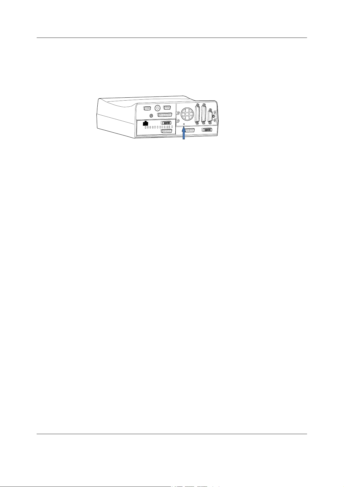
System installation
3.4.6 Replacing PC boards
For service procedures refer to Part II.
1. Make sure that the power is turned off the Monitor and unplug the power cord. Press and
hold the service reset button on the rear panel of the F-CPU for at least five seconds or
until an audible tone is heard (see Figure 15).
Figure 15 Service reset button
2. Remove the PC board (two screws). Notice that the PC boards can be removed only in
certain order.
WARNING The circuit boards contain sensitive integrated circuits that can be
damaged by an electrostatic discharge. Careful handling of the boards is
therefore essential.
NOTE: The B-UPI4NET contains components on both sides of the PCB. Therefore, the installation
of B-UPI4NET should be handled with extra care. Detach the board from the frame carefully by
pulling it from the X3 connector (25 pin female D-connector).
3. Remove the new PC board from the protective antistatic packaging. Always hold the
board by the edges and wear a wrist-grounding strap.
4. Insert the new PC board into the vacant slot and firmly press the board into position.
Secure the board (two screws).
5. Insert all other circuit boards, cover plates and EMC plates.
6. Reconnect the power cord.
3.4.7 Performing Factory Reset
NOTE: The factory reset is necessary after downloading of monitor software and after
replacing the CPU board or SRAM/Timekeeper battery
NOTE: A factory reset will restore all customized defaults, including language selection, to
factory defaults.
1. Press the
2. Select Install/Service and password (16-4-34).
3. Select Service and password (26-23-8).
4. Select Set/Test and perform a Factory Reset.
5. The monitor will perform an automatic restart. After the restart is completed, restart the
monitor also manually by the On/Standby switch.
Monitor Setup key.
.
33
Document no. M1137263-04
Page 46

Datex-Ohmeda S/5 Anesthesia and Critical Care Monitors
3.5 Displays
D-LCC12A
Figure 16 Display options
3.5.1 Main displays
The main display options are integrated with an S/5 Command Bar and a ComWheel:
• 15” Flat Panel Display, D-FPD15
• S/5 LCD Display, D-LCC12A
NOTE: Only one LCD display (D-LCC12) that uses B-DISPX as the power supply can be used in a
system where one F-CU5(P) 5-Module Frame is connected to Central Unit F-CPU.
NOTE: An LCD display that uses B-DISPX as the power supply (D-LCC12) cannot be used in a
system where two F-CU5(P) Central Units are connected to one F-CPU.
3.5.2 Secondary displays
19” medical grade display
•
However, the secondary display can also be either of the main displays listed above.
3.5.3 3rd display
The 3rd display can be installed together with the Display Controller Board, B-DISPX. All S/5
main softwares support the use of the 3
NOTE: Due to increased power consumption only two LCD displays should take power via the
Central Unit simultaneously.
D-FPD15
rd
display.
19’’ medical grade display
3.5.4 Display installation
NOTE: Please pay attention to any additional instructions that may accompany the displays
and / or their installation equipment. The instructions described below in this manual may not
contain all the necessary information.
NOTE: When connecting a display with a DVI-D type digital video cable, some adjustments are
not needed and may not be available in the display’s on-screen adjustment menu (OSD).
WARNING A secondary display must be supplied from an additional transformer
providing at least basic isolation (isolating or separating transformer).
34
Document no. M1137263-04
Page 47
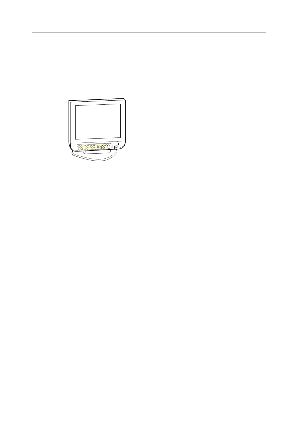
System installation
WARNING The displays must only be used together with the original type of power
adapter.
CAUTION The LCD displays are fragile. Ensure that the LCD displays are not placed near a
heat source or exposed to mechanical shocks, pressure, moisture, or direct
sunlight.
3.5.5 15” Flat Panel Display, D-FPD15
Mounting to Central Unit
Connect the video cable and power adapter cable to the 15” Flat Panel Display, D-FPD15.
Tighten the video cable finger screws. Attach the Command Bar, K-ANEB / K-ICUB into the
keypad holder.
Mount the display together with the desk stand to the Central Unit using the display alignment
studs on the top of the frame (applies to Central Unit, F-CU8 only).
Mounting
Mount the 15” Flat Panel Display, D-FPD15, to a pedestal, wall or ceiling mount, or to a display
arm with appropriate parts.
Connection to Central Unit
1. Make sure that power to the Central Unit is turned off.
2. Remove the connector cover: Press “fixed lever” downward on the back of the display.
Then slip the cover to the direction of the arrow and remove the cover.
3. Connect the AC adapter’s DC plug into the displays power input. Connect the provided
power cord in to the inlet of the auxiliary AC adapter. Then, connect plug to the mains
outlet.
4. Connect the DVI cable to the connector X2 on the CPU board, B-CPU6. Alternatively,
connect the VGA cable to the connector X2 on the CPU board, B-CPU6. Tighten the finger
screws.
WARNING The display must be used only together with the original D-FPD15 power
adapter.
Adjustments
Switch the monitor on. Wait until the normal monitoring screen appears. Perform the following
adjustments, if needed.
1. Resolution setting
Check that the picture on the LCD display screen is clear and stable. Check that the
display screen uses the XGA resolution.
35
Document no. M1137263-04
Page 48
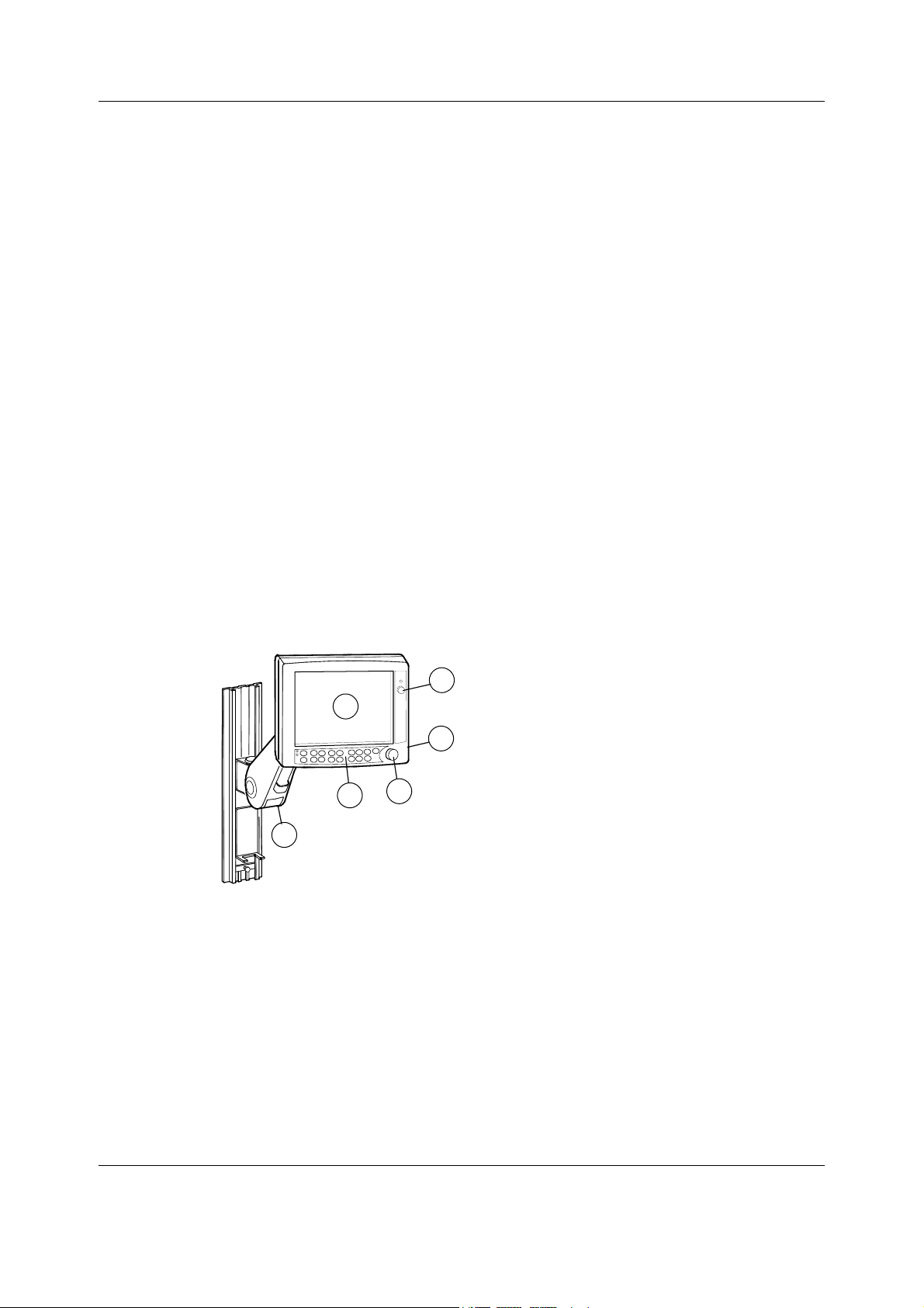
Datex-Ohmeda S/5 Anesthesia and Critical Care Monitors
Install/Service (password 16-4-34) – Installation - Display Setup
NOTE: After changing the resolution, the monitor must be restarted before the new setting
becomes effective. If the resolution setting is not correct after the monitor restart, check that
the resolution jumpers or dip switches on the display controller board are positioned correctly,
see chapter 3.6. Display controller boards.
2. Brightness and contrast adjustments
Press the Control dial while the LCD display is on to activate the OSD menu
(on-screen-display).
NOTE: Pressing the Control dial for more than 2 seconds turns the power off.
Perform the contrast and brightness adjustments if needed. Please refer to the display’s
User’s Manual.
3. Color temperature adjustments
Perform the color adjustments if needed. Please refer to the display’s User’s Manual.
4. Auto Setup
Perform Auto Setup to automatically adjust the screen size, position, phase and clock, if
needed.
This adjustment is available only with analog input (VGA cable). This function is not
available for digital input (DVI).
NOTE: Position adjustments, clock and phase can be adjusted also manually. Please refer to the
display’s User’s Manual.
Exit the OSD menu and go back to the normal screen.
3.5.6 12” LCD Display, D-LCC12A
1
5
6
(1) 12” LCD display, D-LCC12A
(2) Connector for the anesthesia record keeping solution keyboard or Remote Controller
K-REMCO
(3) ON/STBY switch of the monitor
(4) ComWheel
(5) Command bar keys
(6) Display Arm
2
3
4
36
Document no. M1137263-04
Page 49

System installation
Mounting to Display arm
Mount the LCD Display, D-LCC12A to a pedestal, wall or ceiling mount, or to a display arm with
appropriate parts. Connect the video cable to the display and tighten the video cable finger
screws carefully.
CAUTION To prevent any liquid from entering the LCD display casing, do not tilt the LCD
display more than 45 degrees backward or 20 degrees forward.
Connection to Central Unit
1. Make sure that the power to the Central Unit is turned off.
2. Connect the video cable to the X2 connector on the CPU board, B-CPU6. Tighten the
finger screws.
3.5.7 19” medical grade display
Environmental conditions
WARNING The environmental conditions of the 19" Medical Grade Display differ from
the environmental conditions of the S/5 Anesthesia Monitor and Critical
Care Monitor systems.
Atmospheric pressure lower limit
Operating: 697 mbar
The difference in the operating atmosphere pressure lower limit is only in altitudes over 3000 m
(9800 ft). Above this altitude, use another specified display.
Mounting
When using the display with the desk stand option, it must be placed on a flat horizontal
surface. The 19” medical grade display is provided with a desk stand as default with the GCX
adaptor included. Standard VESA mounting solutions can be used with this display.
In order to mount the display with AM and CCM monitors, please see for example the Supplies
and Accessories catalog.
Connection to the Central Unit
Medical grade display requires B-DISPX display controller board.
1. Make sure that power to the Central Unit is turned off.
2. Remove the connector cover: Press “fixed lever” downward on the back of the display.
Then slip the cover to the direction of the arrow and remove the cover.
37
Document no. M1137263-04
Page 50

Datex-Ohmeda S/5 Anesthesia and Critical Care Monitors
3. Connect the AC adapter’s DC plug into the displays power input. Connect the provided
power cord in to the inlet of the auxiliary AC adapter. Then, connect plug to the mains
outlet.
4. Connect the DVI cable to the connector X2 on the CPU board, B-CPU6. Tighten the finger
screws.
A medical grade power supply adapter and the country-specific power cord are included in the
display delivery.
The following cables are included: Analog signal cable (1.8 m long), DVI signal cable (1.8 m long).
Adjustments
The optimal display resolution is SXGA (1280 x 1024). To use the display, a CPU board, B-CPU6
or Display Controller Board B-DISPX is needed.
Changing the screen resolution: Press
select Install/Service (password 16 - 4 - 34),
select Installation - Display Setup.
In Screen 1 ... Screen 3, select the resolution SXGA (1280 x 1024).
After changing the resolution turn the monitor off and on again.
• For details about the general use of the 19" Medical Grade Display refer to the display
manufacturer's user guide delivered with the display.
Monitor Setup,
3.6 Display controller boards
CPU board, B-CPU6 has an integrated display controller, which acts as a controller for the
primary display. In case only one display is used, an optional display controller board is not
needed. Optional displays must be supported by different separate display controller boards,
i.e. the primary display by a primary display controller integrated on the CPU board, B-CPU6,
the secondary display by an optional display controller board and the third display by an
optional secondary display controller board. Consequently, it is possible to configure the
displays separately. One of the displays can, for instance, be used for a continuous display of
trend pages.
NOTE: It is possible to use one display controller to obtain duplicate video signals for two
displays by using the display Y-cable.
3.6.1 Jumper settings
The optional display controller boards require different address settings to operate correctly.
The settings are made through dip switches on B-DISPX. Different settings are illustrated in the
following figures.
Figure 17 Address dip switch settings, B-DISPX
38
Document no. M1137263-04
Page 51

S3 S2
DVI
Connector
Figure 18 Resolution dip switch settings, B-DISPX
3.6.2 Resolution selection for optional B-DISPX
The resolution selection dip switch positions are presented in Figure 18 Resolution dip switch
settings, B-DISPX. If the AUTO mode is selected, the resolution can be set by monitor software.
In other modes, the resolution is set accordingly.
3.6.3 Resolution selection for primary display
Resolution settings are
made by dip switch S3
S3 switches
sw1 sw2
off off
Auto
bdis px_Di pSwit ch.vsd
Bus Connector
SVGA
VGA
XG A
off on
on off
on on
System installation
The resolution selection for primary display is set through the monitor software setting only.
3.7 S/5 Remote Controller, K-REMCO
Connection to Central Unit
Connect the Remote Controller cable to the X11 connector on the CPU board, B-CPU6. Tighten
the finger screws.
39
Document no. M1137263-04
Page 52

Datex-Ohmeda S/5 Anesthesia and Critical Care Monitors
3.8 S/5 Airway Modules
3.8.1 S/5 Compact Airway Modules, E-xxxx
This chapter provides information for installing Compact Airway Modules E-xxxxx.
Figure 19 Compact Airway Module, E-XXXX
Connection to Central Unit
1. Ensure that the module is properly orientated (i.e. module release latch facing downward).
2. Align the module insertion guide slot with the frame insertion guide.
3. Push the module into the frame until it clicks.
NOTE: The Compact Airway Modules cannot be placed into the third and fourth slot from the
right-hand side of the Central Unit F-CU8.
3.8.2 Sample gas exhaust
Preventing operation room pollution
When N2O or volatile anesthetics are used, pollution of the operation room by these gases
should be prevented. Connect the sample gas outlet of the monitor to the scavenging system
or return it to the patient circuit.
NOTE: The sample gas from the E-MiniC can only be connected to the scavenging, not returned
to the patient circuit.
Connect the sample gas outlet of the monitor to the scavenging system either
• through the ventilator, or
• directly to the vacuum scavenging system.
WARNING Strong scavenging suction may change the operating pressure of the
module and cause inaccurate readings or excessive sample gas flow. To
prevent this, there must for example be an opening to room air.
Connect the sample gas outlet only to open scavenging system where gas is removed in room
pressure.
40
Document no. M1137263-04
Page 53

Scavenging through the ventilator reservoir
SAMPLE GAS OUT
Figure 20 Scavenging through ventilator reservoir
1. Connect an exhaust line to the sample gas outlet on the module’s front panel.
2. Attach the other end of the line to the ventilator reservoir. Make sure that the reservoir
tube diameter is at least 2 - 3 times larger than the exhaust line.
System installation
Scavenging through the anesthesia gas scavenging system
Anesthesia machines are equipped with an anesthesia gas scavenging system (AGSS), and in
some machines the sample gas outlet can be connected directly to that.
For example, connect the sample gas outlet to the S/5 Avance:
Figure 21 Connecting the gas module to the scavenging connector of S/5
Avance
NOTE: Refer to the anesthesia machine’s documentation to find out where and how the sample
gas can be connected.
41
Document no. M1137263-04
Page 54

Datex-Ohmeda S/5 Anesthesia and Critical Care Monitors
Connecting directly to the vacuum scavenging system
1. Connect the exhaust line to the monitor’s sample gas outlet.
2. Connect the exhaust line only to an open scavenging system where gas is removed at
room pressure. Do not connect the monitor directly to a vacuum scavenging system.
Returning sampling gas to the patient circuit
The sampling gas can also be returned to the patient circuit. If you use the S/5 Anesthesia
Delivery Unit (ADU), you need an optional adapter connected to the patient breathing tubes.
Take special care when returning sample gas to the patient circuit. For further information,
please contact your GE Healthcare distributor.
NOTE: If E-miniC is being used do not return the sample gas to the patient circuit
SCAVENGING
SAMPLE GAS OUT
Figure 22 Sample gas returned to patient circuit in ADU
3.9 Record Keeping Keyboard for Anesthesia, K-ARKB
3.9.1 Connection to Central Unit
1. Make sure that the power to the Central Unit is turned off.
2. Connect the keyboard-monitor cable to the X2 connector on the Keyboard Interface
Board, B-ARK, and to the connector on the rear of the keyboard. Alternatively you can
connect the cable to a Display Controller Board, B-DISPX. Secure the connection with the
thumbscrew and slip the cable beneath the fasteners.
3.9.2 Connection to LCD Display, D-LCC12A
1. Make sure that the power to the Central Unit is turned off.
2. Connect the Keyboard-LCD Display Cable to the K-ARKB connector on the LCD Display
and to the connector on the rear of the keyboard. Secure the connection with the
thumbscrew and slip the cable beneath the fasteners.
42
Document no. M1137263-04
Page 55

3.10 ARK Barcode Reader, N-SCAN (optional)
3.10.1 Connection to Central Unit/LCD Display or D-LCC12A
The ARK Barcode Reader, N-SCAN, can be connected to the Record Keeping Keyboard for
Anesthesia, K-ARKB, and to the LCD Display or D-LCC12A using a Y-cable as illustrated in
Figure 23 below.
System installation
Figure 23 Barcode Reader connected to LCD Display
The ARK Barcode Reader, N-SCAN, can be connected to the Record Keeping Keyboard for
Anesthesia, K-ARKB as illustrated in Figure 24.
43
Document no. M1137263-04
Page 56

Datex-Ohmeda S/5 Anesthesia and Critical Care Monitors
Figure 24 N-SCAN Barcode Reader connection directly to the keyboard
Barcode Reader is configured compatible to your monitor and necessary information is
delivered with the monitor.
WARNING When using the ARK Barcode Reader, N-SCAN, do not stare into beam.
The N-SCAN is a Class 2 laser product.
3.11 S/5 Extension Frame, F-EXT4, with F-CU8 only
Figure 25 S/5 Extension Frame, F-EXT4
The Extension Frame, F-EXT4, enables the monitor system to be expanded using additional
parameter modules. The Extension Frame is connected to the Central Unit via the Extension
Module, E-EXT. The Extension Module plugs into the Central Unit, F-CU8 in the same way as the
parameter modules.
NOTE: Only one Extension Frame can be connected to each Central Unit, F-CU8.
44
Document no. M1137263-04
Page 57

System installation
3.11.1 Mounting of Extension Frame, F-EXT4
When mounting the Extension Frame, F-EXT4, for instance to an IV pole, make sure that this
does not affect the stability of the IV pole.
3.11.2 Connection to Central Unit
Insert the Extension Module, E-EXT, into the Central Unit. Firmly press the module into position.
Connect the Extension Module cable to the Extension Frame.
3.11.3 Inserting the parameter modules
Insert the parameter modules into Extension Frame slots. Firmly press the modules into
position.
CAUTION Ensure that the module is properly orientated (i.e. module release latch facing
downward) before insertion.
NOTE: Parameter modules with identical functions must not be used simultaneously in the
same monitor system. Take special care not to do this when using the Extension Frame.
NOTE: Modules E-REC/ M-REC, E-MEM/ M-MEM, E-INT/ M-INT, E-CXXXX/ M-CXXXX cannot be
used in the Extension Frame.
3.11.4 Troubleshooting
If a problem occurs during a functional examination, check the components of the monitor
according to the following troubleshooting chart. If the problem persists, please refer to Part II
of this Technical Reference Manual.
Trouble Treatment
Nothing functions. Unplug the Command Bar or Remote Controller cable. Check that the cable is
intact then reconnect the cable.
Unplug the power cord. Check that the cord is intact, then reconnect the cord.
Check that the fuses are intact.
The display does not
function.
A parameter module
does not function.
The Airway Module does
not function.
Unplug the display power cord and the display cable. Check that the cord and
cable are intact, then reconnect the cord and cable.
Unplug the Monitor-LCD Display cable. Check that the cable is intact and
reconnect the cable.
Check that the display brightness is adjusted properly.
Remove and replace the module.
Check that the parameters displayed are configured correctly.
Check that the ‘Occlusion’ or ‘Calibrating Gas Sensor’ messages are not displayed.
Check that a D-fend water trap and a sampling line are attached.
Check that the Gas Interface Board, B-GAS is inserted properly.
Check that the parameters displayed are configured correctly.
Press and hold the Select Agent key for three seconds.
Turn off the power to the Central Unit. Unplug the Gas Interface Cable. Check that
the cable is intact, then reconnect the cable. Turn on the power to the Central
Unit.
Compact Airway Module
does not function.
Remove and replace the module.
45
Document no. M1137263-04
Page 58

Datex-Ohmeda S/5 Anesthesia and Critical Care Monitors
46
Document no. M1137263-04
Page 59

4 Interfacing
External devices can be interfaced with the S/5 Anesthesia and Critical Care Monitors via the
UPI4 and UPI4NET boards, B-UPI4 and B-UPI4NET, via the Interface Module, E-INT, and via the
Device Interfacing Solution, N-DISxxx.
A UPI4 and UPI4NET board can be used for interface with:
• S/5 Anesthesia Delivery Unit
• Printers
• Computers
An E-INT can be used for interface with:
• Datex-Ohmeda monitors
• Various other manufacturers’ monitors
• Various anesthesia machines
Printers and computers can be interfaced via the monitor’s serial or parallel port.
Device specific N-DISxxx modules can be used with:
• Ventilators/ anesthesia machines
Interfacing
• Heart-lung machines
• Monitors
• Blood-gas analyzers
4.1 Interfacing external monitors via Interface Module, E-INT
It is possible to interface Datex-Ohmeda monitors, Critikon Dinamap 1846SX, Abbott Oximetrix
3, Baxter Explorer and Vigilance, Nellcor N-100, N-200 and N-1000 to the S/5 Anesthesia
Monitor or to the S/5 Critical Care Monitor via Interface Module, E-INT. The parameters that are
transferred from external monitors are summarized in tables: Table 4 Transference of
parameters, Datex-Ohmeda monitors and Table 5 Transference of parameters, external
monitors.
The Interface Module, E-INT, has two serial/analog connectors.
WARNING Always make sure that the combination complies with the international
safety standard IEC 60601-1-1 for medical electrical systems and with the
requirements of local authorities.
47
Document no. M1137263-04
Page 60

Datex-Ohmeda S/5 Anesthesia and Critical Care Monitors
Table 4 Transference of parameters, Datex-Ohmeda monitors
Device Waveforms
Numerics Alarms
(analog)
Cardiocap E-INT -> CO
Capnomac
E-INT -> CO
2
, Pleth Et&Fi Airway gases,
2
Capnomac II
Capnomac Ultima E-INT -> CO
Normocap 200
E-INT -> CO
2
2
Normocap 200 OXY
Oscar
E-INT -> CO
, Pleth Et&Fi Airway gases,
2
Oscar II
Oscar OXY
Satlite
E-INT -> CO
2
Satlite II
Satlite Plus
Satlite Trans None SpO
Et&Fi Airway gases,
Respiration rate,
SpO2, Pulse rate
Respiration rate
Et&Fi Airway gases,
Respiration rate,
Spirometry, SpO2,
Pulse rate, Pleth
amplitude
Et&Fi Airway gases,
Respiration rate
Respiration rate,
SpO
Pleth amplitude
SpO2, Pulse rate,
Pleth amplitude
Pleth amplitude
, Pulse rate,
2
, Pulse rate,
2
None
None
CO2, O2, Anesthesia
agent, Respiration
rate, Apnea,
Occlusion, SpO2,
Pulse rate
None
None
None
None
Table 5 Transference of parameters, external monitors
Device Waveforms Numerics Alarms
Critikon
Dinamap 1846SX
Abbott
Oximetrix 3
Baxter
Explorer
Baxter
Vigilance
Nellcor
N-100
N-200
N-1000
None NIBP None
None SvO
None C.O., SvO
/SaO2, CO None
2
REF,
2,
Tblood
None C.O., SvO
C.C.O.,
2,
Tblood
Pleth (analog) SpO
, Pulse rate None
2
4.1.1 Connection to external Datex-Ohmeda monitors
Use the INT-External Device Cable.
1. Make sure that the power to both monitors is turned off.
2. Connect the 9 pin D-connector to the Interface Module, E-INT. Tighten the finger screws.
3. Connect the 25 pin D-connector to the corresponding connector on the other monitor.
Tighten the finger screws.
None
None
48
Document no. M1137263-04
Page 61

Interfacing
4.1.2 Connection to Critikon Dinamap 1846SX, Abbott Oximetrix 3 and Baxter Explorer
Use the INT-External Device Cable.
1. Make sure that the power to both monitors is turned off.
2. Connect the 9 pin D-connector to the Interface Module, E-INT. Tighten the finger screws.
3. Connect the 25 pin D-connector to the connector on the external monitor. Tighten the
finger screws.
4.1.3 Connection to Baxter Vigilance
Use the INT-Baxter Vigilance Cable.
1. Make sure that the power to both monitors is turned off.
2. Connect the 9 pin D-connector to the Interface Module, E-INT. Tighten the finger screws.
3. Connect the other 9 pin D-connector to a corresponding connector on the external
monitor. Tighten the finger screws.
Communication parameters are: baud rate 19200, no parity (none), data bits 8, stop bits 1.
Mode of communication port: IFM out.
4.1.4 Connection to Nellcor N-100 and N-1000
Use the Monitor-Nellcor Cable.
1. Make sure that the power to both monitors is turned off.
2. Connect the 9 pin D-connector to the Interface Module, E-INT. Tighten the finger screws.
NOTE: The X3 and X9 connectors cannot be used when interfacing the S/5 Anesthesia Monitor
or the S/5 Critical Care Monitor with Nellcor N-100 monitors.
3. Connect the other connector to the corresponding connector on the external monitor.
Tighten the finger screws. Connect also the mono connectors on the external monitor.
4.1.5 Connection to Nellcor N-200
Use the Monitor-Nellcor Cable.
1. Make sure that the power to both monitors is turned off.
2. Connect one of the connectors to the corresponding connector on the Interface Module,
E-INT. Tighten the finger screws.
3. Connect the other connector to the corresponding connector on the external monitor.
Tighten the finger screws. Connect also the mono connectors on the external monitor.
Connect also the mono connectors on the external monitor.
49
Document no. M1137263-04
Page 62

Datex-Ohmeda S/5 Anesthesia and Critical Care Monitors
50
Document no. M1137263-04
Page 63

4.2 Interfacing external bedside devices via Device Interfacing Solutions, N-DISxxx
The Device Interfacing Solution, N-DISxxx provides means for transferring physiological,
waveform and event data from various bedside patient care devices to the Datex-Ohmeda
monitoring system. The real-time and trended data can be displayed on the monitor screen
and used for record keeping purposes. The interfacing module reads the data coming from the
external device, converts it to a suitable format and sends it to the monitor. With the Device
Interfacing Solution, N-DISxxx, you can interface up to ten different devices simultaneously.
See the following table of DIS modules and devices that you can interface with the Device
Interfacing Solution.
NOTE: The Device Interfacing Solution (DIS) is only compatible with the S/5 Anesthesia and S/5
Critical Care Monitor when the monitor has B-UPI4NET and S/5 Monitor software rev. 01 or later
installed.
Table 6 DIS modules and interfaced devices
Device Ventilators
N-DISEV4
N-DISPRIM
N-DIS7200
N-DIS840
N-DISS300
N-DIS7900
N-DISAEST
N-DISVENT
5
1
Evita 4
1
Primus
NOTE: Not available in the US
7200 Series Ventilator System
840 Ventilator System
Servo Ventilator 300
3
7900 SmartVent Ventilator
4
Aestiva/5
2
2
4
S/5 Aespire4
Aestiva/5
Aisys Carestation
S/5 Avance
Centiva/5
Engström Carestation
4
4
4
4
4
Interfacing
1 Trademark of Dräger Medical AG & Co
2 Trademark of Nellcor Puritan Bennet Inc
3 Trademark of Maquet Critical Care AB part of the Getinge Group (previously trademark of Siemens)
4 Trademark of GE Healthcare Finland Oy
5 Replaced by N-DISVENT
Device Monitors
N-DISOXIM3
N-DISQVUE
N-DISA2000
N-DISVIGIL
N-DISPICCO
Oximetrix 3
QVue /Q2
A-2000 Bispectral Index Monitoring System
Baxter-Vigilance
PiCCO-Technology4 NOTE: Not available in the US
1
1
2
3
Document no. M1137263-04
51
Page 64

Datex-Ohmeda S/5 Anesthesia and Critical Care Monitors
N-DISRGM
N-DISTONO
N-DISWHITE
RGM Monitor
Tonocap
Capnomac, Capnomac II
Multicap, Normocap, CD2-O2
Capnomac Ultima
Normocap CD-200
Oscar Oxy, Cardiocap 1GS, Cardiocap 2GS
Satlite, Satlite Trans, Satlite Plus
5
5
5
5
5
5
5
5
1 Trademark of Hospira Inc. (previously trademark of Abbott Laboratories)
2 Trademark of Aspect Medical Systems
3 Trademark of Edwards Lifesciences Corporation
4 Trademark of Pulsion Medical Systems
5 Trademark of GE Healthcare Finland Oy
Device Blood gas analyzers
N-DISOPT
AVL Opti CCA
1
Device Heart-lung machines
N-DISHL20
Jostra HL-20
1 Trademark of Diamond Diagnostics Inc
2 Trademark of MAQUET GmbH & Co. KG part of the Getinge Group
2
For specific information on parameters transferred from the interfaced device to the
Datex-Ohmeda monitor and the applicable software versions of the device refer to the
Installation guide accompanying each DIS module.
4.2.1 Device Interfacing Solution components
The Device Interfacing Solution consists of:
− a device specific interfacing module
− a device specific cable
− a bus cable
− a connector for another bus cable
− label specifying the external device
4.2.2 Connections
Connect the device specific cable to the external device and the bus cable to the S/5
Anesthesia / Critical Care Monitor’s UPI4 or UPI4NET board or to the monitor's DIS connector or
to another interfacing module.
52
Document no. M1137263-04
Page 65

Interfacing
(1) label specifying the external device
(2) LED indicators
(3) black bus cable from another
interfacing module, if needed
(4) grey device specific cable to the
communication port of the external
device
(5) black bus cable to the monitor’s DIS
connector (or to another interfacing
module)
Figure 26 Connection cables and LED indicators
WARNING The Anesthesia/Critical Care Monitor, interfacing modules and interfaced
devices must be situated in the same patient environment (as defined in IEC
60601-1-1).
WARNING Connecting electrical equipment together or using the same extension cord
for more than one device may cause their leakage currents to exceed the
limits specified in relevant safety standards. Always make sure that the
combination complies with the international safety standard IEC 60601-1-1
for medical electrical systems and with the requirements of local
authorities.
WARNING The manufacturer guarantees a reliable functioning of the devices with
tested software versions only. Always refer to the Installation guide
accompanying the DIS module and verify the compatibility before use.
4.2.3 Mounting
The DIS module can be mounted on the side panel of the external device. Also IV pole
placement is possible.
NOTE: As the Device Interfacing Solution works only with the device specified in the label of the
interfacing module, it is recommended that the interfacing module always travels along with
the external device.
For mounting accessories, please refer to the “Supplies and Accessories” catalog. See the
following figure for an example of a device interfacing.
53
Document no. M1137263-04
Page 66
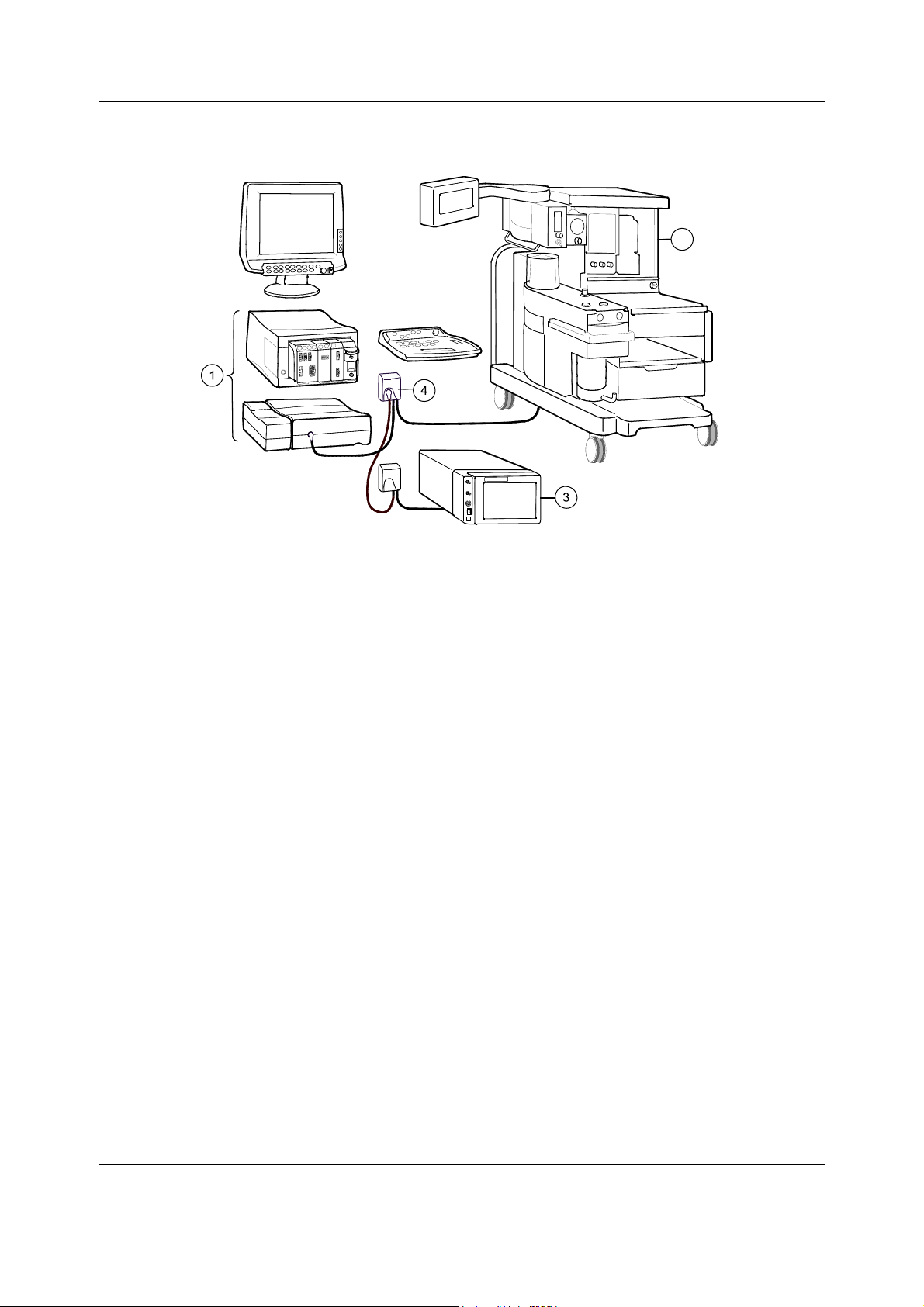
Datex-Ohmeda S/5 Anesthesia and Critical Care Monitors
2
Figure 27 An example of interfacing external devices with Device Interfacing
Solution
(1) Datex-Ohmeda S/5 Anesthesia Monitor (with software L-ANE02(A) or later)
(2) Aestiva/5 anesthesia machine
(3) RGM monitor
(4) Interfacing module
NOTE: You can connect up to ten (10) interfacing modules to one system simultaneously.
Check the maximum number of modules: one meter cable = max. four ten modules, three
meter cable = max. three modules, six meter cable = one module.
WARNING Make sure that the interfacing module is always used in vertical position to
prevent water from entering the module.
WARNING Make sure that you are connecting the interfacing module to the device
specified in the label. Always verify the compatibility of the software
versions before use.
4.2.4 Selecting the external device
1. Turn off the monitor.
2. Turn off the external device.
3. Connect the interfacing module to the monitor’s UPI4NET board or to the connector for
N-DIS or to another interfacing module.
4. Connect the device specific cable to the external device and turn the external device on.
5. Turn the monitor on. The monitor identifies the connected device automatically.
54
Document no. M1137263-04
Page 67

4.2.5 Functional check
There are two ways to check the function of the Device Interfacing Solution:
1. Press the
2. Select Interfacing and open the Status Page menu. The status page shows you the
current communication status of the interfacing module (1 - 10).
NOTE: The status message ‘Connected’ appears on the Status Page after you have connected
the external device to the interfacing module and turned it on. Note also that the monitor and
the interfacing module must be operational.
• Check the LED indicators on the interfacing module (the green LED indicates physical
connections, the yellow LED software selections)
:
GREEN YELLOW INDICATION
Interfacing
Monitor Setup key.
lit dark
dark
lit lit
dark dark
lit
Physical connections between the monitor, interfacing
module and external device are in order and the device
has been selected in the menu.
There is something wrong with the physical connections
between the monitor, interfacing module and external
device. The external device has not been selected in the
menu.
Physical connections between the monitor, interfacing
module and external device are in order but the external
device has not been selected in the menu.
The interfacing module is not connected to the monitor.
4.2.6 Selecting the parameter data source
Select the external device via Monitor Setup - Interfacing menu:
• Select the desired parameter, for example Gases.
• Select the desired source by name, for example Aestiva.
NOTE: The name of the device is visible on the list only if the device is correctly connected.
Detailed information about interfacing module related mountings, connections and settings is
included in the installation guides that are delivered with the interfacing modules.
55
Document no. M1137263-04
Page 68

Datex-Ohmeda S/5 Anesthesia and Critical Care Monitors
4.3 Interfacing Datex-Ohmeda Anesthesia Delivery Unit
It is possible to interface the Datex-Ohmeda Anesthesia Delivery Unit to the S/5 Anesthesia
Monitor via the UPI Board, B-UPI4 or UPINET Board, B-UPI4NET. The data link is bi-directional.
The parameters transferred to the Anesthesia Delivery Unit are summarized in Table 7 and the
events transferred to the S/5 Anesthesia Monitor are summarized in Table 8. The events are
transferred continuously once a minute or during the system check procedure and appear in
the trend pages or in the anesthesia record. The transfer of events requires record-keeping
software.
4.3.1 Interconnection
Use the ADU-AS/3 Monitor Cable.
4.3.2 Setting interfacing parameters on the S/5 Anesthesia Delivery Unit
1. Press the Setup key.
2. Select Install password 10.
3. Select Interfacing and choose S/5 AM.
4. Press the
Normal Screen key.
4.3.3 Setting interfacing parameters on the S/5 Anesthesia Monitor
No settings are required on the S/5 Anesthesia Monitor.
Table 7 Parameters transferred from S/5 Anesthesia Monitor to S/5
Anesthesia Delivery Unit
Waveforms Numerics
CO
2
Et & Fi CO2 %
Et & Fi O
O
2
(I-E)
Et & Fi N
Et & Fi AA%
Vol Exp MV
Vol Exp TV
%
2
% difference
O%
2
56
Document no. M1137263-04
Page 69

Table 8 Events transferred from S/5 Anesthesia Delivery Unit to the
S/5 Anesthesia Monitor
Events transferred once a minute
Ventilator settings Ventilation (mode)
Tidal Volume
Minute Volume
Resp. Rate
I:E Times: inp
I:E Times: exp
InspPause
Ventilator measurements Ppeak
Pplat
Peep
Pmin
Fresh gas settings Agent name
Agent % in fresh gas
Total flow
O
flow
2
O flow
N
2
Air flow
Interfacing
Events transferred during system check
System check test results Gas Delivery: Agent
Gas Delivery: N
Leak Tests: AUTO
AUTO Leak (ml/min)
Leak Test: MAN
MAN Leak (ml/min)
Number of confirmed checklist items
Bypass Check
O
2
4.4 Interfacing Dräger Cicero, Cato, Julian and Narkomed 2C (by NAD)
It is possible to interface Dräger Cicero and Cato to the S/5 Anesthesia Monitor or to the
S/5 Critical Care Monitor via the Interface Module, E-INT.
NOTE: The Interface Board must be equipped with revision 881652-4.0 software or later.
The parameters transferred to the S/5 Anesthesia Monitor or S/5 Critical Care Monitor are
summarized in Table 9 and Table 10.
NOTE: Some of the summarized parameters (waveforms or numerics) may not be available in
all device versions.
WARNING Always make sure that the combination complies with the international
safety standard IEC 60601-1-1 for medical electrical systems and with the
requirements of local authorities.
57
Document no. M1137263-04
Page 70

Datex-Ohmeda S/5 Anesthesia and Critical Care Monitors
4.4.1 Interconnection
Use the INT-External Device Cable, except for Julian and Cicero EM, in which case use the
INT-Julian/Cicero EM cable.
1. Make sure that the power to both monitors is turned off.
2. Connect the 9 pin D-connector to the Interface Module, E-INT. Tighten the finger screws.
3. Connect the 25 pin D-connector to a corresponding connector on the anesthesia
machine. The connector is labeled 'RS-232-C'. Tighten the finger screws.
4.4.2 Setting communication parameters
Set the communication parameters for Cicero and Cato to RS-232: 9600, e, 8, 1 (MEDIBUS 3.00).
In all cases please refer to the documentation provided by Dräger.
4.4.3 Setting interfacing parameters on the S/5 Anesthesia Monitor or S/5 Critical Care Monitor
1. Press the Monitor Setup key.
2. Select Install/Service (password 16-4-34).
3. Select Service (password 26-23-8) - Parameters - More...
4. Select Interface and combine a required parameter with the external monitor. Two
letters, al, denote alarm integration. The selection will be automatically stored in
permanent memory.
5. Press the
Normal Screen key.
Table 9 Parameters transferred from Dräger Cicero monitor to S/5
Anesthesia Monitor or S/5 Critical Care Monitor
Selection Waveforms Numerics States
Gases / SSS CO
SpO
2
(kPa, mmHg, %) CO2 Fi & Et (kPa, %)
2
Fi & Et (%)
O
2
O Fi & Et (%)
N
2
RR (CO
) (1/min)
2
AA Fi & Et (%)
Tidal Volume insp. (1)
Minute Volume exp. (1)
Ppeak (mbar)
Pplat (mbar), PEEP (mbar)
Pleth (% full scale) SpO2 (%)
Pulse rate (1/min)
None
Probe Off
58
Document no. M1137263-04
Page 71

Table 10 Parameters transferred from Dräger Cato, Julian and Narkomed 2C
(NAD) monitor to the S/5Anesthesia Monitor or S/5Critical Care
Monitor
Selection Waveforms Numerics States
Interfacing
Gases / SSS CO2 (kPa, mmHg, %) CO2 Fi & Et (kPa, %)
O
Fi & Et(%)
2
N2O Fi & Et (%)
RR (CO2) (1/min)
AA Fi & Et (%)
Tidal Volume insp. (1)
Minute Volume exp. (1)
Ppeak (mbar)
Pplat (mbar); not in Narkomed 2C
PEEP (mbar)
SpO
2
Pleth (% full scale) SpO2 (%)
Pulse rate (1/min)
NOTE: The transference of parameters illustrated in Table 7 and Table 8 represents the
maximum. Some of these parameters may not be available in all device versions.
NOTE: The transference of waveforms requires the MEDIBUS real-time extension and, in Cato
monitors, waveforms are available only on port 1.
None
Probe Off
59
Document no. M1137263-04
Page 72

Datex-Ohmeda S/5 Anesthesia and Critical Care Monitors
4.5 Interfacing printer
It is possible to interface a laser printer (either serial or parallel) to the S/5 Anesthesia Monitor
and S/5 Critical Care Monitor via the UPINET Board, B-UPI4NET. The printer must be PCL5 or
PCL6 compatible and it should contain at least 2 MB of memory.
4.5.1 Interconnection
Use a commercial serial printer interface cable or the UPI4 - Printer parallel interface cable
713701 or a standard parallel port printer cable for connecting the printer to the monitor.
1. Make sure that the power on both units is turned off.
2. Connect the cable to the corresponding connector on the B-UPI4NET.
3. Connect the cable to the corresponding connector on the printer.
WARNING Always make sure that the combination complies with the international
safety standard IEC 60601-1-1 for medical electrical systems and with the
requirements of local authorities.
WARNING Connecting the power supply cord of the printer to the wall power outlet
may cause the printer leakage current to exceed the limit specified for
medical equipment. A printer must be supplied from an additional
transformer providing at least basic isolation (isolating or separating
transformer).
4.5.2 Setting interfacing parameters on the printer
NOTE: For more information about printer settings, please refer to the documentation provided
with the printer.
4.5.3 Setting interfacing parameters on the S/5 Anesthesia Monitor or S/5 Critical Care Monitor
Select the appropriate printer connection in the Record/Print menu.
4.6 Interfacing computer
It is possible to interface a computer to the S/5 Anesthesia Monitor and to the Critical Care
Monitor.
Contact your authorized GE Healthcare distributor for further advice on computer interface.
WARNING Always make sure that the combination complies with the international
safety standard IEC 60601-1-1 for medical electrical systems and with the
requirements of local authorities.
WARNING Connecting the power supply cord of the computer to the wall power outlet
may cause the computer leakage current to exceed the limit specified for
medical equipment. A computer must be supplied from an additional
transformer providing at least basic isolation (isolating or separating
transformer).
60
Document no. M1137263-04
Page 73

4.7 Output signals
4.7.1 UPI4NET Board output signals
Analog/ digital output signals on the connectors X7 can be used for interfacing with other
devices. The pin assignments are illustrated in tables/pictures below.
Table 11 Coding element connector, X4
9 pin female D-connector Pin Signal
Interfacing
1
5
9
1
6
2
3
4
5
6
7
8
9
IDCS1 (chip select)
IDCL (clock)
IDDI (data in)
IDDO (data out)
IDPE (protect enable)
+5Vdc
N/C (Direct ECG in B-UPI4NET rev.00 only)
Nurse call
GND
Table 12 Defib & IABP sync connector, X7 (B-UPI4NET -02) and on the front of
F-CPU
Mini DIN7 connector Pin Signal
1
2
3
5
6
7
8
Defib_sync_out
Reserved
Analog GND
Digital GND
GND
Pressure_out
Direct_ECG_out
4.7.2 Digital outputs
The digital output signals are as follows:
Defibrillation Sync B-UPI4NET -02 (X7 pin1),
The defibrillation sync signal is generated by the ECG. When activated, the signal is set to a high
level and then set back to a low level after 10 ms. The signal is regenerated only after returning
to the low level. The high level ranges from 2.8 to 5 V, while the low level ranges from 0 to 0.8 V.
The delay from the R wave peak to the start of the signal is 35 ms maximum.
Nurse Call (X4 pin 8)
The Nurse Call signal is generated by red and yellow alarms. When activated, the signal is set to
the high state and remains at the high state until the alarm situation is over or the
ALARM
0.8 V.
key is pressed. The high level range is from 2.8 to 5 V, while low state range is from 0 to
SILENCE
61
Document no. M1137263-04
Page 74

Datex-Ohmeda S/5 Anesthesia and Critical Care Monitors
If the output signals are used simultaneously with the coding element, the B-UPINET Y-cable,
order number 889308, is recommended.
4.7.3 Analog outputs
Direct ECG B-UPI4NET -02 (X7 pin 8)
Delay (max.): <15 ms
Gain ECG (out)/ECG (in): 1 V/mV ±20%
Pacer: 5 V and 2 ms pulse
Output range: ±4 V
Noise: 50 mVpp max.
The signal requires input impedance of 100 kΩ.
NOTE: The ECG signal is based on the ECG measurement of the Hemodynamic Modules,
E-PRESTN (all variations) and E-PSM / E-PSMP. The ECG signal from the modules is channel 1
(ECG1). The channels 2 and 3 (ECG2, ECG3) are not transmitted. Make sure that the signal in
channel 1 (ECG1) is good enough (extensive QRS for IABP synchronization). For further
information, please contact your authorized GE Healthcare distributor.
Pressure out B-UPI4NET -02 (X7 pin 7)
Invasive pressure signal: From pressure labelled ‘Art’
Delay (max.): <35ms
Gain signal (out) / Pressure (in): 10 mV/mmHg ±20%
Output range: -0.4 V to +3.2 V
Noise: 50 mVpp max.
The signal requires input impedance of 100 kΩ.
4.7.4 S/5 Pressure Temp Module, E-PT, output signals
The signal output connector on the Pressure Temp Module, E-PT, can be used to interface some
models of IABPs to the S/5 Anesthesia Monitor and S/5 Critical Care Monitor. The pin
assignments are illustrated in Table 13. Please contact your local distributor for more
information.
WARNING Always make sure that the combination complies with the international
safety standard IEC 60601-1-1 for medical electrical systems and with the
requirements of local authorities.
Table 13 Signal output connector pin assignments
Pin Signal
1
2
3
4
Output signals
ECG out, ECG1 1V / 1mV
Pressure out, P3 1V / 100mmHg
ECG out, ECG1 1V / 1mV
ECG out, ECG1
Pressure out, P3
ECG out, ECG1
Ground
62
Document no. M1137263-04
Page 75

5 Functional check
These instructions include procedures for a functional check for Datex-Ohmeda S/5 Anesthesia
Monitor and S/5 Critical Care Monitor. The functional check is mandatory after monitor
installation.
These instructions include a “Functional check form, Datex-Ohmeda S/5 AM, CCM” which may
Functional check
be used when performing the procedures. The symbol
the check form contains space to record the results of the particular procedure. The
procedures should be performed in ascending order, bypassing those that are not applicable
for a particular monitor.
All menu selections related to Datex-Ohmeda products are written in following typeface:
e.g. Parameters - Gas Unit.
As you enter the service menus, you need the following passwords:
" in the instructions indicates that
Monitor Setup - Install/Service (password 16-4-34) - Service (password 26-23-8)
In case you evaluate the measurement accuracy with a patient simulator, add simulator’s
accuracy specification to the one of the monitor.
An electrical safety check and a leakage current test are recommended to be performed prior
to the monitor installation.
5.1 Recommended tools
NOTE: Use only properly maintained, calibrated and traceable measurement equipment for the
specified calibrations and adjustments to ensure accuracy.
For product(s) Tool Order No.
Airway modules
Compact Airway Module,
E-CAiO(VX)
Calibration gas and regulator 755583/755534*
Compact Airway Module, E-COVX Calibration gas and regulator 755587/755534*
Compact Airway Module, E-CO(V) Calibration gas and regulator 755581/755534*
E-miniC Calibration gas and regulator 755580/755534*
Compact Airway Module, E-COVX,
E-CAiOVX
All Airway modules w/ (V) Spirometry tube, 2 m 890031
Hemodynamic modules
Hemodynamic modules w/ (P) NIBP cuff and hose 2753E (cuff)
Hemodynamic modules w/
(P)E-PSMP
Sampling line, 2 m 73318
D-lite 733950
877235 (hose)
Pressure manometer
InvBP transducer 70077-001
Document no. M1137263-04
63
Page 76

Datex-Ohmeda S/5 Anesthesia and Critical Care Monitors
For product(s) Tool Order No.
Multi-Link ECG accessories, IEC
E-PSM(P)/ E-PRESTN
- Multi-link 3-leadwire set 412682-003
- Multi-link 5-leadwire set 412681-003
- Multi-link 5-leadwire set, C2-C6 416467-004
E-PRESTN w/ (E12) - Multi-link 12-lead ECG trunk
416035-002
cable
or Multi-Link ECG accessories, AHA
E-PSM(P)/ E-PRESTN - Multi-link 3-leadwire set 412682-001
- Multi-link 5-leadwire set 416681-001
- Multi-link 5-leadwire set, V2-V6 416467-003
E-PRESTN w/ (E12) - Multi-link 12-lead ECG trunk
416035-001
cable
E-PSM(P)/ E-PRESTN SpO
E-NSATX Nellcor OxiMax SpO
finger probe OXY-F-UN
2
Interconnect Cable OXY-ES3
SpO
2
interconnect
2
cable
Nellcor SpO
E-MASIMO Masimo SpO
Masimo SpO
Masimo SpO
sensor
2
probe
2
sensor
2
interconnect cable
2
E-OSAT OxyTip® + Integrated Finger Sensor OXY-F4-N
Hemodynamic modules w/ (T) Temperature test set 884515
Hemodynamic E-Modules w/ (NIBP) Adult NIBP cuff hose with cuff ID 2021285-001
NIBP cuff 2753E
Pressure manometer
Infant cuff hose without cuff ID 414874-001
E-COP/ E-COPSv C.O. Catheter cable 16590
E-COPSv SvO
BIS Module, E-BIS BIS simulator or
simulator 890121
2
BIS Sensor simulator
900509
900508
E-ENTROPY Entropy simulator N-ES
Entropy sensor cable 8002964
E-MEM MemCard – Data or Menu 893860 (Menu, English)
887045 (Data, English)
NOTE: * Ensure that the calibration gas and regulator are functioning properly before
calibration. Perform annual maintenance on the regulator as required. For more information
64
Document no. M1137263-04
Page 77

see section “Adjustments and calibrations” in Compact Airway modules slot in E-Modules
Technical Reference Manual.
For details on recommended accessories see “Supplies and Accessories” catalog.
5.1.1 Hemodynamic patient simulators
The following tables present the patient simulators’ compatibility with each hemodynamic
module, and the accessories needed:
Table 14 Patient simulators’ compatibility with each hemodynamic module
Functional check
Patient simulator
Module Parameter
E-PSM(P), E-PRESTN ECG Ok Multilink ECG acc. Not compatible
T 402015-004 402015-004 and
InvBP Ok M1010858
ECG
M1010831 MedSim 874027
M1010832
Table 15 Adapter cables for hemodynamic patient simulators
Patient simulator Adapter cables for simulators
Hemodynamic patient simulator - Dual temperature adapter cable 402015-004
Hemodynamic patient simulator - Dual Inv.BP adapter cable 2005772-001
Medsim - Temperature adapter cable M1010832
Medsim - Inv.BP adapter cable M1010858
Lionheart & MPS450 - Temperature adapter cable M1010846
Lionheart & MPS450 - Inv.BP adapter cable M1010862
5.2 Visual inspection
Make sure that the monitor is switched to standby.
Disconnect the mains power cord from the monitor.
If the monitor is connected to the Datex-Ohmeda Network, disconnect the Mon-Net cable
from the monitor. If the Memory Module, E-MEM is connected, remove any memory cards.
1. Check all units visually
Check that all parts are intact and that the cables and screws are connected and
tightened properly. Especially check the following parts:
− Video displays: the display power cord is locked to the display.
− F-CU5(P), F-CPU and N-AC: all the screws and the equipotential tap on the N-AC are
tightened properly.
Document no. M1137263-04
65
Page 78

Datex-Ohmeda S/5 Anesthesia and Critical Care Monitors
− F-CU8: the equipotential tap and all the screws are tightened properly.
− sampling line is connected to the Airway Module, if installed.
Check that modules go in smoothly and lock up properly in all module slots.
CAUTION Ensure that the module is properly orientated (i.e. module release latch facing
downward) before insertion.
"
5.3 Functional inspection
WARNING Handle the water trap and its contents as you would any body fluid.
Infectous hazard may be present.
5.3.1 General
1. F-CU5: Connect all the parts together. Check that the cables and screws are tightened
properly. Connect the mains power cord to the N-AC Power Unit.
F-CU8: Connect the mains power cord to the F-CU8.
Check that the stand-by LED is lit.
2. Switch the monitor on.
Check that the monitor starts up properly, i.e. a normal start-up sound is heard from the
loudspeaker, the alarm LEDs turn on and off, and the monitoring screen appears.
No error messages should appear on the screen.
3. Configure the screen for the parameters that are connected.
4. Enter the Service Menu.
When applicable, check from the corresponding Parameters submenu that the Timeouts,
Bad checksums and Bad c-s by mod values of inserted modules are not increasing faster
than by 5 per second. Check also that the module memories have passed the internal
memory test, i.e. RAM, ROM and EEPROM all state OK.
If connected, the recorder should record two lines of start-up information.
"
Preset the measurement settings for those parameters that are connected, for example:
Record/Print - Record Waveforms - Waveform 1 - ECG1
- Waveform 2 - P1
- Waveform 3 - P2
Invasive Pressures - P1 ‘ART’ Setup -- Label – ART
Pulse Oximetry -Pleth Scale –AUTO
or
Others -SPO2 Setup - Pleth Scale –AUTO
66
Document no. M1137263-04
- P2 ‘CVP’ Setup -- Label – CVP
- P3 Setup -Label –PA
- P4 Setup -Label -P4
- P5 Setup -Label -P5
- P6 Setup -Label -P6
Page 79

5.3.2 Display(s)
1. Check that the picture on the screen is correct. Readjust the picture with the adjustment
knobs or with the display menu keys, if necessary.
"
5.3.3 Keyboard(s)
Functional check
Airway Gas -Spirometry Setup -Scaling -Indep.
-Paw Scale –20
-Flow Scale –15
or
Ventil.-Spirometry Setup -Scaling -Indep.
-Paw Scale –20
-Flow Scale –15
Others -Resp Setup -Size -1.0
- Resp Rate Source – AUTO
- Measurement – ON
- Detection Limit – AUTO
1. Tests with all the connected keyboards:
− Press the
the cursor in the menu moves correspondingly. Select Normal Screen and check
that the menu disappears from the screen.
Tests with the Command Bar:
− Press the
in the menu moves correspondingly. Select Normal Screen and check that the
menu disappears from the screen.
Check the rest of the menu keys by pressing them one by one.
Tests with the ARK Keyboard:
− Enter the Keyboard service menu
− Check functioning of the ComWheel.
− Press all keys, except
from the loudspeaker, or the Message count value in the service menu increases.
− Press the
on the monitor screen.
Tests with the Remote Controller:
− Enter the Keyboard service menu.
− Check the function of the ComWheel.
− Press all keys. Check that each key produces a sound from the loudspeaker, or the
Message count value in the service menu increases.
Monitor Setup key. Turn the ComWheel in both directions and check that
Help key. Turn the ComWheel in both directions and check that the cursor
Modify and Print. Check that each key produces a sound
Modify and Print keys and check that the corresponding menus appear
"
67
Document no. M1137263-04
Page 80

Datex-Ohmeda S/5 Anesthesia and Critical Care Monitors
5.3.4 5-Module Central Unit, F-CU5/ 8-Module Central Unit, F-CU8
1. Check that all the fans in the N-AC, F-CPU and F-CU5(P) are / the frame fan in F-CU8 is
running.
2. Check that the clock on the screen shows correct time. Readjust the time and date, if
necessary.
"
5.3.5 Extension Frame, F-EXT4
1. If the F-EXT4 contains a fan, check that the fan is running.
2. Check that the modules in the F-EXT4 are recognized i.e. the required parameter
information is shown on the monitor screen.
"
5.3.6 Compact Airway Module, E-CXXXXX
Wait until the message ‘Calibrating gas sensor’ disappears from the screen.
1. Check that the fan is running.
2. If the module contains membrane keys on the front panel, check the function of each of
the membrane keys.
"
Compact Airway Modules with the Patient Spirometry option
3. Connect a clean spirometry tube and D-lite to the module. Connect the sampling line.
Breathe through the wider side of the D-lite.
Check that the flow waveform moves downwards when you breathe in and upwards
when you breathe out.
"
For all Compact Airway Modules
4. Block the tip of the sampling line with your finger and check that the message ‘Sample
line blocked’ appears on the monitor screen within 30 seconds.
5. Detach the D-fend and check that the message ‘Check D-fend’ appears on the monitor
screen within 30 seconds.
6. Breathe to the sampling line briefly. Check that the CO2 information is updated on the
screen.
"
68
Document no. M1137263-04
Page 81

5.3.7 Single width Airway Module, E-miniC
Wait until the message ‘Calibrating gas sensor’ disappears from the screen.
1. Block the tip of the sampling line with your finger and check that the message ‘Sample
line blocked’ appears on the monitor screen within 30 seconds.
2. Detach the Mini D-fend and check that the message ‘Check D-fend’ appears on the
monitor screen within 30 seconds.
Breathe to the sampling line briefly. Check that the CO2 information is updated on the
screen.
"
5.3.8 Multiparameter Hemodynamic Modules
ECG and RESP measurements
1. Connect an ECG cable to the module. Connect the cable leads to a patient simulator.
Check that all ECG and impedance respiration information is shown on the monitor
screen as configured on the simulator.
Turn the simulator off. Check that the ‘Asystole’ message appears on the screen.
Functional check
"
Temperature measurement
2. Check the temperature channels with a patient simulator.
Check that temperature measurement information is shown on the monitor screen as
configured on the simulator.
"
Invasive blood pressure measurement
3. Check the function of the front panel membrane keys.
4. Check the InvBP channels with a patient simulator.
Zero the InvBP channels and check that the values and waveforms correspond to the
simulator settings.
"
SpO2 measurement
5. Connect an SpO2 finger probe to the module. Check that the message ‘Probe off’ is shown
when the probe is not connected to a finger.
6. Attach the SpO2 probe to your finger. Check that a reading of 95-99 and a pleth
waveform appear on the screen
"
Non invasive blood pressure measurement
7. Check the function of the front panel membrane keys.
8. Attach an adult NIBP cuff onto your arm and check that the module identifies the cuff, i.e.
the text ‘Adult’ appears in the NIBP digit field for a short time.
69
Document no. M1137263-04
Page 82

Datex-Ohmeda S/5 Anesthesia and Critical Care Monitors
Perform a NIBP measurement and check that the module gives a reasonable measured
result.
"
5.3.9 Pressure/Pressure Temp Modules, E-P, E-PT
Invasive blood pressure measurement
1. Check the function of the front panel Zero P3 key.
2. Check the InvBP channel with a patient simulator.
Zero the InvBP channel. Then check that the values and waveforms correspond to the
simulator settings.
"
Temperature measurement
3. Check the temperature channels with a patient simulator.
Check that the temperature measurement information is shown on the monitor screen as
configured on the simulator.
"
5.3.10 Dual pressure Module, E-PP
1. Check the function of the front panel Zero P5 and Zero P6 keys.
2. Check the InvBP channels with a patient simulator.
Zero the InvBP channels. Then check that the values and waveforms correspond to the
simulator settings.
"
5.3.11 Cardiac Output Modules, E-COP, E-COPSv
Invasive blood pressure measurement
1. Check the function of the front panel Zero P4 key.
2. Check the InvBP channel with a patient simulator.
Zero the InvBP channel. Then check that the values and waveforms correspond to the
simulator settings.
"
Cardiac Output measurement
3. Check the function of the front panel Start C.O. key.
"
70
Document no. M1137263-04
Page 83

5.3.12 Masimo Compatible Saturation module, E-MASIMO
1. Connect a Masimo SpO2 finger probe to the module. Check that the message ‘Check
probe’ is displayed on the screen within 30 seconds.
2. Attach the SpO2 probe on your finger. Check that a reading of 95-100 and a proper SpO2
waveform appear.
"
5.3.13 Nellcor Compatible Saturation module, E-NSATX
1. Connect a Nellcor SpO2 finger probe to the module. Check that the message ‘Pulse
search ’ is shown and check that the message 'No probe' changes to ‘Check probe’ within
30 seconds.
2. Attach the SpO2 probe on your finger. Check that a reading of 95-100 and a proper SpO2
waveform appear.
"
5.3.14 BIS Module, E-BIS
Functional check
1. Connect the BIS module to the monitor frame.
Check that ‘Cable off’ is displayed in the BIS waveform field.
2. Connect the DSC to the module.
Check that the ‘No sensor’ message appears in the waveform field.
3. Check the function of the front panel membrane keys.
4. Open the BIS Setup menu:
NOTE: If the sensor is not connected, the
"
5.3.15 Entropy Module, E-ENTROPY
1. Check the function of the front panel membrane keys.
2. Connect the Entropy sensor cable and Entropy simulator to the module. Check that
‘Checking sensor’ text and an image appear in the waveform numeric field. Wait for a
while and check that all sensors show PASS.
3. Check that the EntrEEG waveform and RE and SE values appear on the monitor screen.
"
5.3.16 Memory Module, E-MEM
BIS - BIS Setup and check that Test DSC shows PASS.
Check Sensor key is inoperative.
1. Insert a Data card or a Menu card to the slot.
Check that the corresponding symbol appears on the monitor screen.
"
71
Document no. M1137263-04
Page 84

Datex-Ohmeda S/5 Anesthesia and Critical Care Monitors
5.3.17 Recorder module
1. Press the Record Wave module key and check that the module starts recording the
selected waveforms. Press the
2. Check that the quality of the recordings is acceptable.
Stop module key to stop recording.
"
5.3.18 Network connection
1. Check that the Mon-Net cable connector and the Identification plug are clean and intact,
then connect them to the CPU/UPI4NET Board.
Check that the monitor connects to the network, i.e. the network symbol appears under
the clock on the upper right-hand corner of the screen. Also a message regarding the
connected Central should appear in the message field on the screen.
"
5.3.19 Interface Module, E-INT
1. Make sure that the monitor receives all necessary parameter data from the connected
devices. Check the screen configuration and the related interfacing settings, if necessary.
Monitor Setup – Interfacing
"
5.3.20 Interface module for PSM, E-INTPSM
1. Make sure that the monitor receives all necessary parameter data from the connected
E-PSM(P) module. Check the screen configuration and the related interfacing settings, if
necessary.
Monitor Setup – Interfacing
"
5.3.21 Device Interfacing Solution, N-DISxxx
1. Make sure that the monitor receives all necessary parameter data from the connected
devices. Check the screen configuration and the related interfacing settings, if necessary.
Check also via the Interfacing menu that the connected DIS module status is correct:
Monitor Setup - Interfacing - Status Page
"
72
Document no. M1137263-04
Page 85

5.3.22 General
•
• Perform final cleaning
• Fill in all necessary documents
Functional check
Switch the monitor to standby
"
73
Document no. M1137263-04
Page 86

Datex-Ohmeda S/5 Anesthesia and Critical Care Monitors
74
Document no. M1137263-04
Page 87

6 General troubleshooting
Monitor not functioning
On/Stby sw itch "ON"?
Dis play c onnected and
pow ered? Keyboard
connected?
No
Connect and chec k
General troubleshooting
Yes
pow er cord connected?
Connect pow er cord and
Remov e all mo d u les and tur n
Ma ins
Possible intrconnecting
cables connected?
No
interconnecting cables
pow er on
Stby-led lit?
Yes
Start-up texts
appear on
screen?
Yes
Cloc k et c . data
appears on the
screen?
No
Yes
Monitor starts
functioning
No
No
No
Monitor starts
functioning?
Dis connect and reconnect the
power cord.
Monitor starts
functioning?
No
Yes
Keyboard trouble. See troubleshooting in
Command Bar s sl o t .
No
Faulty Central Unit.
See troubleshooting in Frame slot.
Yes
Yes
The problem w as caused by
loosen unit(s)
The pow er supply unit w as shut
dow n by instant over voltage in the
ma in s .
The problem w as caused by
loosen pow er cord
Yes
Plug in a module
Module data
appears on the
screen?
No
Another
moudle w orks in
same place?
Figure 28 S/5 AM, CCM general troubleshooting flowchart
No
Yes
Yes
Pick up the next module.
Faulty module.
See troubleshooting in module slot.
Faulty Module Frame or Central Unit.
See troubeshooting in Frame slot.
F- CU5_Gener al tr oubleshooti ng.vsd
75
Document no. M1137263-04
Page 88

Datex-Ohmeda S/5 Anesthesia and Critical Care Monitors
6.1 Software troubleshooting
For information on software troubleshooting, see “Software Download Tool - User Instructions.”
76
Document no. M1137263-04
Page 89
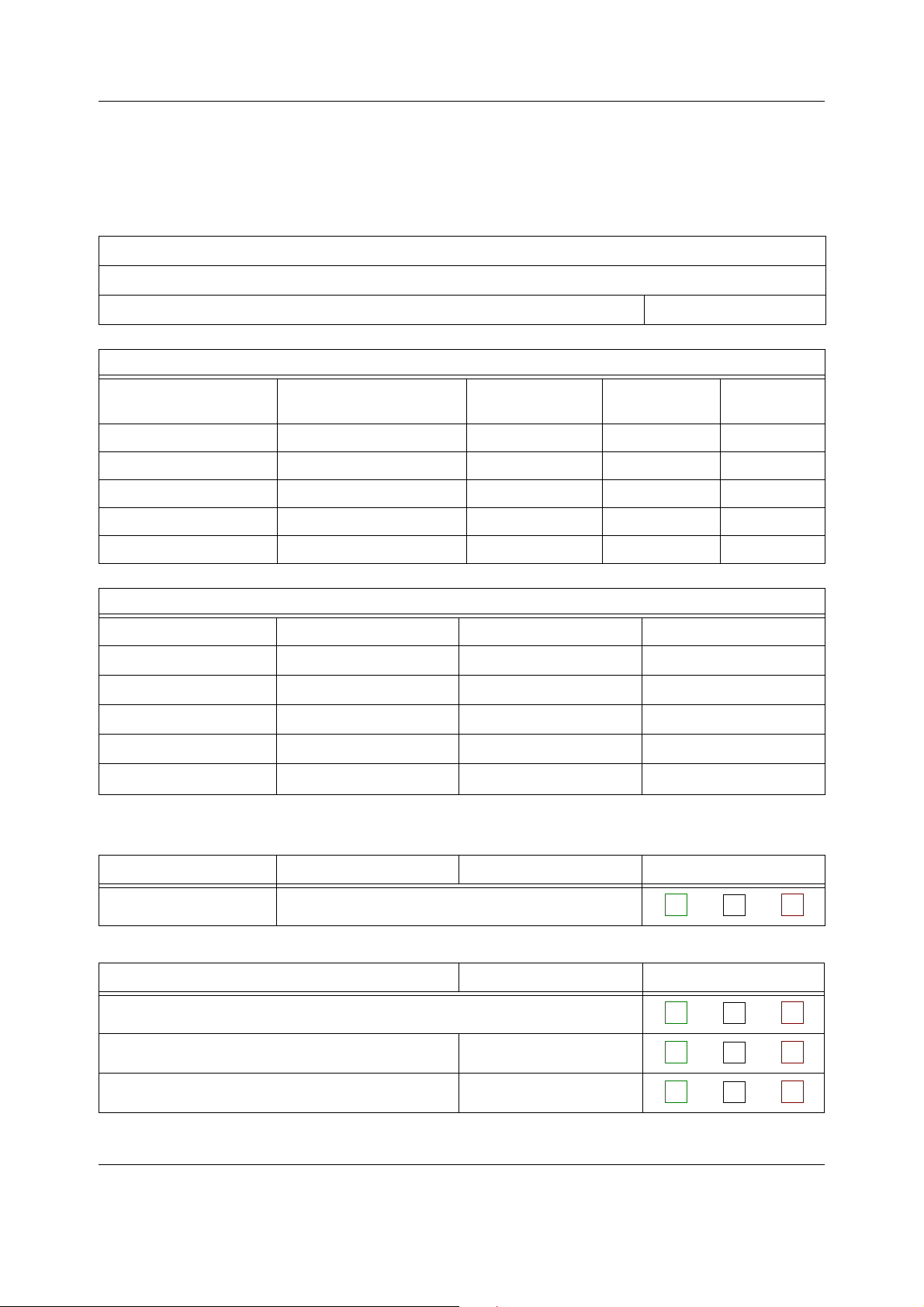
Appendix A Functional check form, Datex-Ohmeda S/5 AM, CCM
APPENDIX A: Functional check form, Datex-Ohmeda S/5 AM, CCM
Customer
Service
Service engineer
Measuring equipment / test gases used:
Equipment / tool / gas: Manufacturer: Model/Type/Part
Number:
Monitor Installation
F-CU5(P) B- N-
F-CPU B-
N-AC B-
F-CU8 B-
L- K-
Date
Serial Number /
ID:
Calibration
Date:
D- D-
OK = Test OK N.A. = Test not applicable Fail = Test failed
Visual Inspection OK N.A. Fail
1. Check all units visually
Functional Inspection OK N.A. Fail
5.3.1. General
5.3.2. Display(s) S/N
5.3.3. Keyboard(s) S/N
Document no. M1137263-04
A1(4)
Page 90

Datex-Ohmeda S/5 Anesthesia and Critical Care Monitors
Functional Inspection OK N.A. Fail
5.3.4. 5-Module Central Unit, F-CU5/ 8-Module Central
Unit, F-CU8
5.3.5. Extension Frame, F-EXT4 S/N
Notes
S/N
5.3.6. Compact Airway Module, E-CXXXXX S/N
. Compact Airway Modules with the Patient Spirometry option
. For all Compact Airway Modules
5.3.7. Single width Airway Module, E-miniC S/N
Notes
5.3.8. Multiparameter Hemodynamic Modules S/N
. ECG and RESP measurements
. Temperature measurement
. Invasive blood pressure measurement
. SpO2 measurement
. Non invasive blood pressure measurement
Notes
5.3.9. Pressure/Pressure Temp Modules, E-P, E-PT S/N
. Invasive blood pressure measurement
. Temperature measurement
5.3.10. Dual pressure Module, E-PP S/N
Notes
A2(4)
Document no. M1137263-04
Page 91

Appendix A Functional check form, Datex-Ohmeda S/5 AM, CCM
Functional Inspection OK N.A. Fail
5.3.11. Cardiac Output Modules, E-COP, E-COPSv S/N
. Invasive blood pressure measurement
. Cardiac Output measurement
Notes
5.3.12. Masimo Compatible Saturation module,
E-MASIMO
5.3.13. Nellcor Compatible Saturation module,
E-NSATX
5.3.14. BIS Module, E-BIS S/N
5.3.15. Entropy Module, E-ENTROPY S/N
S/N
S/N
5.3.16. Memory Module, E-MEM S/N
5.3.17. Recorder module S/N
5.3.18. Network connection S/N
5.3.19. Interface Module, E-INT S/N
5.3.20. Interface module for PSM, E-INTPSM S/N
5.3.21. Device Interfacing Solution, N-DISxxx S/N
S/N
S/N
S/N
S/N
S/N
S/N
S/N
A3(4)
Document no. M1137263-04
Page 92
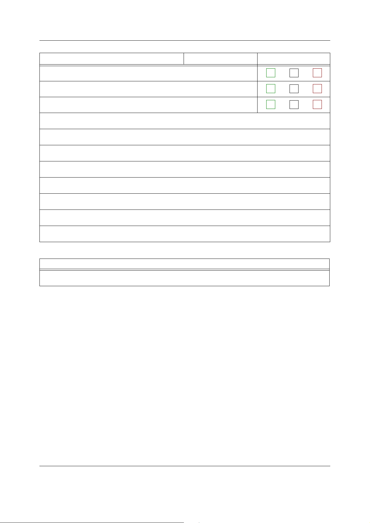
Datex-Ohmeda S/5 Anesthesia and Critical Care Monitors
Functional Inspection OK N.A. Fail
5.3.22. General
• Perform final cleaning
• Fill in all necessary documents
Notes
Signature
A4(4)
Document no. M1137263-04
Page 93

Appendix A ElectroMagnetic Compatibility
APPENDIX B: ElectroMagnetic Compatibility
Table 1 Guidance and manufacturer’s declaration – electromagnetic
emissions
Guidance and manufacturer’s declaration – electromagnetic emissions
The S/5™ AM or CCM is intended for use in the electromagnetic environment specified below. The
customer or the user of the S/5™ AM or CCM should assure that it is used in such an environment.
Emissions test Compliance Electromagnetic environment - guidance
RF emissions
CISPR 11
RF emissions
CISPR 11
Harmonic emissions
IEC 61000-3-2
Voltage fluctuations/
flicker emissions
IEC 61000-3-3
Group 1 The S/5™ AM or CCM uses RF energy only for its internal function.
Therefore, its RF emissions are very low and are not likely to
cause any interference in the nearby electronic equipment.
Class A The S/5™ AM or CCM is suitable for use in all establishments
other than domestic and those directly connected to the public
Class A
Complies
low-voltage power supply network that supplies buildings used
for domestic purposes.
B1(6)
Document no. M1137263-04
Page 94

Datex-Ohmeda S/5 Anesthesia and Critical Care Monitors
Table 2 Guidance and manufacturer’s declaration – electromagnetic
immunity
Guidance and manufacturer’s declaration – electromagnetic immunity
The S/5™ AM or CCM is intended for use in the electromagnetic environment specified below. The customer or
the user of the S/5™ AM or CCM should assure that it is used in such an environment.
Immunity test IEC 60601 test level Compliance level Electromagnetic environment -
guidance
Electrostatic
discharge (ESD)
IEC 61000-4-2
Electrical fast
transients/bursts
IEC 61000-4-4
Surge
IEC 61000-4-5
Voltage dips, short
interruptions and
voltage variations on
power supply lines
IEC 61000-4-11
±6 kV contact
±8 kV air
±2 kV for power
supply lines
±1 kV for input/output
lines
±1 kV differential
mode
±2 kV common mode
<5 % U
T
(>95 % dip in UT)
for 0.5 cycle
40 % U
T
(60 % dip in UT)
for 5 cycles
70 % U
T
(30 % dip in UT)
for 25 cycles
±6 kV contact
±8 kV air
±2 kV for power
supply lines
±1 kV for input/output
lines
±1 kV differential
mode
±2 kV common mode
(2
<5 % U
(1
T
(>95 % dip in UT)
for 0.5 cycle
40 % U
(1
T
(60 % dip in UT)
for 5 cycles
70 % U
(1
T
(30 % dip in UT)
for 25 cycles
Floors should be wood, concrete or
ceramic tile. If floors are covered with
synthetic material, the relative
humidity should be at least 30 %.
Mains power quality should be that of
a typical commercial or hospital
environment.
Mains power quality should be that of
a typical commercial or hospital
environment.
Mains power quality should be that of
a typical commercial or hospital
environment. If user of the S/5™ AM or
CCM requires continued operation
during power mains interruptions, it is
recommended that the
S/5™ AM or CCM be powered from an
uninterruptible power supply or a
battery.
(2
<5 % U
Power frequency
T
(>95 % dip in UT)
for 5 sec
3 A/m 3 A/m Power frequency magnetic field
<5 % U
(>95 % dip in UT)
for 5 sec
(50/60 Hz) magnetic
field
IEC 61000-4-8
NOTE U
(1
(2
is the a.c. mains voltage prior to application of the test level.
T
S/5™ AM or CCM equipped with 5-Module Frame F-CU5(P), Power Unit N-AC and Central Processor Unit F-CPU.
S/5™ AM or CCM equipped with 8-Module Frame F-CU8..10.
(1
T
should be at levels characteristic of a
typical location in a typical
commercial or hospital environment.
B2(6)
Document no. M1137263-04
Page 95

Appendix A ElectroMagnetic Compatibility
Table 3 Guidance and manufacturer’s declaration – electromagnetic
immunity
Guidance and manufacturer’s declaration – electromagnetic immunity
The S/5™ AM or CCM is intended for use in the electromagnetic environment specified below. The customer or
the user of the S/5™ AM or CCM should assure that it is used in such an environment.
Immunity test IEC 60601 test level Compliance
level
Conducted RF
IEC 61000-4-6
Radiated RF
IEC 61000-4-3
3 Vrms
150 kHz to 80 MHz
3 Vrms
150 kHz to 80 MHz
3 V/m
80 MHz to 2.5 GHz
3 V/m
80 MHz to 2.5 GHz
3 Vrms
1 Vrms
3 V/m
1 V/m
(1
(2
Electromagnetic environment - guidance
Portable and mobile RF communications equipment
should be used no closer to any part of the S/5™ AM
or CCM, including cables, than the recommended
separation distance calculated from the equation
applicable to the frequency of the transmitter.
Recommended separation distance
d 1.2 P=
d 3.5 P=
d 1.2 P=
d 2.3 P=
d =3.5 P
80 MHz to 800 MHz
800 MHz to 2.5 GHz
80 MHz to 800 MHz
d =7.0 P
where P is the maximum output power rating of the
transmitter in watts (W) according to the transmitter
manufacturer and d is the recommended separation
distance in metres (m).
Field strengths from fixed RF transmitters, as
determined by an electromagnetic site survey,
should be less than the compliance level in each
frequency range.
Interference may occur in the vicinity of equipment
marked with the following symbol:
800 MHz to 2.5 GHz
a
b
B3(6)
Document no. M1137263-04
Page 96

Datex-Ohmeda S/5 Anesthesia and Critical Care Monitors
NOTE 1 At 80 MHz and 800 MHz, the higher frequency range applies.
NOTE 2 These guidelines may not apply in all situations. Electromagnetic propagation is affected by
absorption and reflection from structures, objects and people.
a
Field strengths from fixed transmitters, such as base stations for radio (cellular/cordless) telephones and land mobile
radios, amateur radio, AM and FM radio broadcast and TV broadcast cannot be predicated theoretically with accuracy.
To assess the electromagnetic environment due to fixed RF transmitters, an electromagnetic site survey should be
considered. If the measured field strength in the location in which the S/5™ AM or CCM is used exceeds the applicable
RF compliance level above, the S/5™ AM or CCM should be observed to verify normal operation. If abnormal
performance is observed, additional measures may be necessary, such as reorienting or relocating the S/5™ AM or
CCM.
b
Over the frequency range 150 kHz to 80 MHz, field strengths should be less than 3 V/m or 1 V/m (1.
(1
For impedance RESP measurement. For invasive pressure measurement in M-series modules except M-PRE(S)TN. The
invasive pressure measurement compliance level is dependent on the transducer used, and only the lower level is
guaranteed for all transducers.
(2
For BIS measurement in E-BIS/M-BIS and RESP measurement in M-(P)RE(S)TN and invasive pressure measurement in
M-COPSv/E-COPSv and M-COP/E-COP modules. The invasive pressure measurement compliance level is dependent on
the transducer used, and only the lower level is guaranteed for all transducers.
B4(6)
Document no. M1137263-04
Page 97

Appendix A ElectroMagnetic Compatibility
Table 4 Recommended separation distances between portable and mobile RF
communications equipment and the S/5™ AM or CCM
Recommended separation distances between portable and mobile RF
communications equipment and the S/5™ AM or CCM
The S/5™ AM or CCM is intended for use in an electromagnetic environment in which radiated RF
disturbances are controlled. The customer or the user of the S/5™ AM or CCM can help prevent
electromagnetic interference by maintaining a minimum distance between portable and mobile RF
communications equipment (transmitters) and the S/5™ AM or CCM as recommended below, according to
the maximum output power of the communications equipment.
Rated maximum
output power of
transmitter
W
0.01 0.12
0.1 0.38
11.2
10 3.8
100 12
150 kHz to 80 MHz
Separation distance according to frequency of transmitter
m
d 1.2 P=
d 3.5 P=
80 MHz to 800 MHz
d 1.2 P=
(1
d 3.5 P=
(2
800 MHz to 2.5 GHz
0.12
0.35
(1
0.35
(2
0.38
1.1
(1
1.1
(2
1.2
3.5
(1
3.5
(2
3.8
11
(1
11
(2
12
35
(1
35
(2
d 1.2 P=
d = 7.0 P
0.23
0.70
0.73
(2
2.2
2.3
(2
7.0
7.3
(2
22
23
(2
70
(2
(2
For transmitters rated at a maximum output power not listed above, the recommended separation
distance d in meters (m) can be estimated using the equation applicable to the frequency of the
transmitter, where P is the maximum output power rating of the transmitter in watts (W) according to the
transmitter manufacturer.
NOTE 1 At 80 MHz and 800 MHz, the separation distance for the higher frequency range applies.
NOTE 2 These guidelines may not apply in all situations. Electromagnetic propagation is affected by
absorption and reflection from structures, objects and people.
(1
For impedance RESP measurement. For invasive pressure measurement in M-series modules except M-PRE(S)TN. The
invasive pressure measurement compliance level is dependent on the transducer used, and only the lower level is
guaranteed for all transducers.
(2
For BIS measurement in E-BIS/M-BIS and RESP measurement in M-(P)RE(S)TN and invasive pressure measurement in
M-COPSv/E-COPSv and M-COP/E-COP modules. The invasive pressure measurement compliance level is dependent on
the transducer used, and only the lower level is guaranteed for all transducers.
Document no. M1137263-04
B5(6)
Page 98

Datex-Ohmeda S/5 Anesthesia and Critical Care Monitors
For your notes:
B6(6)
Document no. M1137263-04
Page 99

Datex-Ohmeda
S/5
Anesthesia Monitor
TM
TM
S/5
Critical Care Monitor
Planned Maintenance Instructions
Conformity according to the Council Directive 93/42/EEC concerning Medical Devices
CAUTION: U.S. Federal law restricts this device to sale by or on the order of a licensed medical practitioner.
Outside the USA, check local laws for any restriction that may apply.
All specifications subject to change without notice.
Document number M1125633-06
June 18, 2009
GE Healthcare Finland Oy
Helsinki, Finland
P.O. Box 900
FI-00031 GE, FINLAND
Tel: +358 10 39411
Fax: +358 9 1463310
www.gehealthcare.com
Copyright © 2009 General Electric Company. All rights reserved.
Madison, WI 53707-7550, USA
Datex-Ohmeda Inc.
Tel: +1 608 221 1551
Fax: +1 608 222 9147
P.O. Box 7550
Page 100

 Loading...