


Tec7
Table of contents
 Loading...
Tec 7 Vaporizer
User’s Reference Manual

User Responsibility
w
CAUTION
This Product will perform in conformity with the description thereof contained
in this User’s Reference manual and accompanying labels and/or inserts,
when assembled, operated, maintained, and repaired in accordance with the
instructions provided. This Product must be checked periodically. A defective
Product should not be used. Parts that are broken, missing, plainly worn,
distorted, or contaminated should be replaced immediately. Should repair or
replacement become necessary, Datex-Ohmeda recommends that a
telephonic or written request for service advice be made to the nearest
Datex-Ohmeda Customer Service Center. This Product or any of its parts
should not be repaired other than in accordance with written instructions
provided by Datex-Ohmeda and by Datex-Ohmeda trained personnel. The
Product must not be altered without the prior written approval of
Datex-Ohmeda. The user of this Product shall have the sole responsibility for
any malfunction which results from improper use, faulty maintenance,
improper repair, damage, or alteration by anyone other than Datex-Ohmeda.
U.S. Federal law restricts this device to sale by or on the order of a
licensed medical practitioner. Outside the U.S.A, check local laws
for any restriction that may apply.
Datex-Ohmeda products have unit serial numbers with coded logic which
indicates a product group code. The year of manufacture and a sequential
unit number for identification.
AAA A 12345
T
his alpha character indicates the year of product
manufacture and when the serial number was
assigned; “C” = 1999, “D” = 2000, “E” = 2001,
etc. “I” and “O” are not used.

1 Introduction
2 Description
3 Setup and Mounting Procedure
Table of Contents
Precautions . . . . . . . . . . . . . . . . . . . . . . . . . . . . . . . . . . . . . . . . . . . . . . . . . . . 1-1
Symbols . . . . . . . . . . . . . . . . . . . . . . . . . . . . . . . . . . . . . . . . . . . . . . . . . . . . . . 1-2
What is a Tec 7 Vaporizer? . . . . . . . . . . . . . . . . . . . . . . . . . . . . . . . . . . . . . . . 2-1
Components . . . . . . . . . . . . . . . . . . . . . . . . . . . . . . . . . . . . . . . . . . . . . . . . . . 2-3
Control dial . . . . . . . . . . . . . . . . . . . . . . . . . . . . . . . . . . . . . . . . . . . . . . . . 2-3
Safety interlocks . . . . . . . . . . . . . . . . . . . . . . . . . . . . . . . . . . . . . . . . . . . 2-3
Vaporizer identification label . . . . . . . . . . . . . . . . . . . . . . . . . . . . . . . . . 2-3
Vaporizer mounting procedure . . . . . . . . . . . . . . . . . . . . . . . . . . . . . . . . . . . . 3-1
Mounting the vaporizer . . . . . . . . . . . . . . . . . . . . . . . . . . . . . . . . . . . . . . 3-2
4 Operating Instructions
Checking the vaporizer for correct mounting . . . . . . . . . . . . . . . . . . . . . . . . . 3-4
Removing the vaporizer from a manifold . . . . . . . . . . . . . . . . . . . . . . . . . . . . 3-4
Setting the dial . . . . . . . . . . . . . . . . . . . . . . . . . . . . . . . . . . . . . . . . . . . . . . . . 4-1
Filling and draining the vaporizer . . . . . . . . . . . . . . . . . . . . . . . . . . . . . . . . . . 4-3
Filling procedure with funnel filler . . . . . . . . . . . . . . . . . . . . . . . . . . . . . . 4-5
Draining procedure with funnel filler . . . . . . . . . . . . . . . . . . . . . . . . . . . 4-6
™
Filling procedure with Easy-Fil
Draining procedure with Easy-Fil . . . . . . . . . . . . . . . . . . . . . . . . . . . . . . 4-8
Filling procedure with Quik-Fil™ . . . . . . . . . . . . . . . . . . . . . . . . . . . . . . . 4-9
Draining procedure with Quik-Fil . . . . . . . . . . . . . . . . . . . . . . . . . . . . .4-10
. . . . . . . . . . . . . . . . . . . . . . . . . . . . . . . 4-7
1175-0013-000
i

Tec 7 Vaporizer
5 Maintenance
User maintenance . . . . . . . . . . . . . . . . . . . . . . . . . . . . . . . . . . . . . . . . . . . . . . 5-1
Maintenance intervals . . . . . . . . . . . . . . . . . . . . . . . . . . . . . . . . . . . . . . . 5-1
Cleaning . . . . . . . . . . . . . . . . . . . . . . . . . . . . . . . . . . . . . . . . . . . . . . . . . . . . . . 5-2
External cleaning . . . . . . . . . . . . . . . . . . . . . . . . . . . . . . . . . . . . . . . . . . . 5-2
Internal contamination . . . . . . . . . . . . . . . . . . . . . . . . . . . . . . . . . . . . . . 5-2
Output concentration check . . . . . . . . . . . . . . . . . . . . . . . . . . . . . . . . . . 5-2
Checking the calibration . . . . . . . . . . . . . . . . . . . . . . . . . . . . . . . . . . . . . . . . . 5-3
Analytical techniques . . . . . . . . . . . . . . . . . . . . . . . . . . . . . . . . . . . . . . . 5-4
Service Policy . . . . . . . . . . . . . . . . . . . . . . . . . . . . . . . . . . . . . . . . . . . . . . . . . . 5-5
6 Principle of Operation
7 Specifications
Interlock mechanism . . . . . . . . . . . . . . . . . . . . . . . . . . . . . . . . . . . . . . . . . . . . 6-1
Delivery of gas/agent vapor . . . . . . . . . . . . . . . . . . . . . . . . . . . . . . . . . . . . . . 6-1
Overview . . . . . . . . . . . . . . . . . . . . . . . . . . . . . . . . . . . . . . . . . . . . . . . . . . 6-1
Bypass circuit . . . . . . . . . . . . . . . . . . . . . . . . . . . . . . . . . . . . . . . . . . . . . . 6-2
Vaporizing chamber circuit . . . . . . . . . . . . . . . . . . . . . . . . . . . . . . . . . . . 6-2
Calibration . . . . . . . . . . . . . . . . . . . . . . . . . . . . . . . . . . . . . . . . . . . . . . . . . . . . 7-1
Performance . . . . . . . . . . . . . . . . . . . . . . . . . . . . . . . . . . . . . . . . . . . . . . . . . . . 7-2
Weight and dimensions . . . . . . . . . . . . . . . . . . . . . . . . . . . . . . . . . . . . . . . . . 7-2
Flow characteristics . . . . . . . . . . . . . . . . . . . . . . . . . . . . . . . . . . . . . . . . . . . . . 7-3
Effects of variables . . . . . . . . . . . . . . . . . . . . . . . . . . . . . . . . . . . . . . . . . . . . . 7-8
Anesthetic agent consumption . . . . . . . . . . . . . . . . . . . . . . . . . . . . . . . . 7-8
Barometric pressure . . . . . . . . . . . . . . . . . . . . . . . . . . . . . . . . . . . . . . . . 7-8
Ambient temperature . . . . . . . . . . . . . . . . . . . . . . . . . . . . . . . . . . . . . . . 7-9
Back pressure . . . . . . . . . . . . . . . . . . . . . . . . . . . . . . . . . . . . . . . . . . . . . 7-9
Carrier gas composition . . . . . . . . . . . . . . . . . . . . . . . . . . . . . . . . . . . .7-10
Warranty
ii
Time out of service . . . . . . . . . . . . . . . . . . . . . . . . . . . . . . . . . . . . . . . . .7-10
Effects of variables . . . . . . . . . . . . . . . . . . . . . . . . . . . . . . . . . . . . . . . . 7-10
1175-0013-000

1 Introduction
Precautions
ww
ww
WARNING Do not fill the vaporizer with any agent other than the agent specified on
the front label. The vaporizer is designed for that agent only. If any
substance other than that specified is used, patient injury could occur.
United States (U.S.) Federal law restricts this device to sale by or on the
order of a licensed medical practitioner. Outside the U.S., check local
laws for any restrictions that may apply.
Do not attempt to use a vaporizer that has been dropped. A dropped
vaporizer MUST be sent to the nearest Datex-Ohmeda Field Operations
Unit for servicing.
Do not use malfunctioning equipment. Make all necessary repairs or
have the equipment serviced by an authorized Datex-Ohmeda service
center. After repair, test the equipment to ensure that it is functioning
properly in accordance with the manufacturer’s published
specifications.
1175-0013-000
1-1
y
Tec 7 Vaporizer
Symbols
Important
ww
ww
WARNING Warnings tell about a condition that can cause injury to the operator or
European Standard EN 740 that an appropriate gas monitor is used to monitor the concentration of anesthetic
agent vapor in the inspiratory gas when the vaporizer is in operation in order to provide
protection against hazardous output in the event of a device malfunction.
Datex-Ohmeda strongly recommends the use of anesthesia gas monitoring with this
equipment. Refer to local standards for mandatory monitoring.
Requests for servicing facilities, advice or assistance must be addressed to a local
Datex-Ohmeda office.
Additional copies of this manual, can be requested from a local Datex-Ohmeda Field
Operations Unit or a Datex-Ohmeda Authorized Distributor.
Datex-Ohmeda strongly recommends that you keep all relevant documentation,
including this manual and accompanying labels, immediately available to all users.
Warnings and Cautions tell you about conditions that can occur if you do not follow all
instructions in this manual.
the patient.
Anesthetic Workstations and Their Modules
requires
onl
SEV
ISO
ENF
HAL
ww
ww
CAUTION Cautions tell about a condition that can cause damage to the
equipment. Read and follow all warnings and cautions.
Caution: federal law prohibits dispensing
without prescription.
Sevoflurane
Isoflurane
% v/v
OFF symbol/OFF setting
Percentage of anesthetic vapor per total volume.
Lock
z
Enflurane
Unlock
Z
Halothane
Maximum Agent Level
Minimum Agent Level Stock number
Systems with this mark agree with the European
Council Directive (93/42/EEC) for Medical
Devices when they are used as specified in their
User’s Reference manuals. The xxxx is the
certification number of the Notified Body used
by Datex-Ohmeda's Quality Systems.
w
NN
NN
Caution or Warning
Direction of flow
Serial number
1-2
1175-0013-000

2 Description
What is a Tec 7 Vaporizer?
The Tec 7 Vaporizer is designed for use in continuous flow techniques of inhalation
anesthesia. Each vaporizer is agent specific and is clearly labeled with the anesthetic
agent that it is designed for.
The vaporizer is temperature, flow and pressure compensated so that its output
remains relatively constant despite cooling due to evaporation, variations in inlet flow
and fluctuating pressures as described in Section 7, Effects of Variables.
The vaporizer is designed to be used on Selectatec
vaporizer can be installed on other Selectatec Manifolds but the interlock system is
designed to function on Selectatec Series Mounted Manifolds only. Mounting a Tec 7
Vaporizer on a Selectatec 7 Compatibility Block is not recommended.
®
Series Mounted Manifolds. The
1175-0013-000
2-1

Tec 7 Vaporizer
AB80008
Figure 2-1 • Tec 7 Vaporizer
w WARNING Improper use may result in patient injury.
This manual and its associated documentation must be studied before
any attempt is made to install, operate or clean any part of the Tec 7
Vaporizer.
The performance of the anesthesia machine and vaporizer can be
degraded if the machine and vaporizer are mis-matched.
Only operate the vaporizer with dry medical gases.
If a vaporizer containing agent in the sump has been inverted, connect it
to a gas scavenging system, set the dial to 5% and purge the vaporizer
with the carrier gas at 5 liters/minute for 5 minutes.
ww
ww
CAUTION The vaporizer is intended to be operated in its upright position.
Turn the vaporizer to when it is not in use.
2-2
1175-0013-000

Components
2 Description
Control dial
Safety interlocks
w WARNING Earlier versions of the Selectatec Series Mounted Manifold that provide
A single control dial with a concentration scale calibrated in percentage of anesthetic
agent vapor per total volume (% v/v) sets the desired concentration of the anesthetic
agent.
A dial release in the dial assembly helps prevent accidental displacement of the
control dial from the position. To select an ON setting, squeeze the dial release
and simultaneously rotate the dial counter-clockwise.
The dial and dial release are designed to enable an ON setting to be selected using
only one hand.
The vaporizer incorporates an interlock mechanism. This mechanism also interfaces
with the Selectatec
• The vaporizer must be locked onto the manifold before it can be turned ON.
• Only one vaporizer at a time can be turned ON when two or more vaporizers are
fitted on a Selectatec
• The gas flow enters only the vaporizer that is turned ON.
• Any unwanted anesthetic trace vapor is minimized after a vaporizer is turned to
.
®
Series Mounted Manifold to help satisfy the following criteria:
®
Series Mounted Manifold.
mounting positions for three vaporizers require that if only two vaporizers
are fitted, then the center position must be occupied. If the center
position is not occupied, the interlock that helps ensure that only one
vaporizer at a time can be turned ON is ineffective.
Vaporizer identification
label
1175-0013-000
Later versions of the Selectatec Series Mounted Manifold that provide mounting
positions for three vaporizers incorporate an additional interlock that helps ensure
that only one vaporizer at a time can be turned ON even if the center position is not
occupied.
A vaporizer identification label is affixed to the back panel of the vaporizer as
illustrated on Fig. 2-2.
An anesthesia system fitted with a vaporizer identification unit uses this label to
identify the vaporizer type.
2-3

Tec 7 Vaporizer
w WARNING Do not affix any additional labels or markings to the back panel. They
may adversely affect the operation of the vaporizer identification unit.
1
H
A
L
O
T
H
A
N
E
1. Vaporizer identification label
Figure 2-2 • Vaporizer identification label
AB80011
2-4
1175-0013-000

3 Setup and Mounting Procedure
Vaporizer mounting procedure
The vaporizer is designed to be used on Selectatec Series Mounted Manifolds. The
vaporizer can be installed on other Selectatec Manifolds but the interlock system is
designed to function on Selectatec Series Mounted Manifolds only.
Mounting a Tec 7 Vaporizer on a Selectatec 7 Compatibility Block is not
recommended.
ww
ww
WARNING Do not lift or support the vaporizer by holding the control dial. Handle the
vaporizer with care at all times.
Before mounting a vaporizer onto the Selectatec Series manifold,
ensure that each manifold port valve O-ring is intact and that there is no
foreign matter around the mating surfaces. A damaged O-ring and/or
foreign matter around the mating surfaces can cause leaks.
Earlier versions of the Selectatec Series Mounted Manifold that provide
mounting positions for three vaporizers require that if only two vaporizers
are fitted, then the center position must be occupied. If the center
position is not occupied, the interlock that helps ensure that only one
vaporizer at a time can be turned ON is ineffective.
Do not use a vaporizer if the liquid level decreases below the minimum
level.
1175-0013-000
Before using a vaporizer allow it to attain the ambient temperature of the
location in which it has to be used.
3-1
Tec 7 Vaporizer
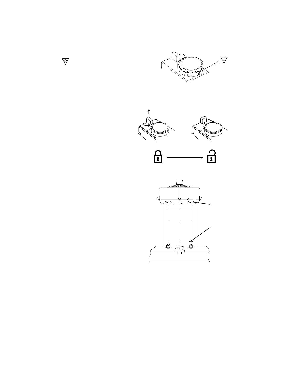
Mounting the vaporizer
Step 1
Set the dial to .
Step 2
Unlock the locking lever.
• Turn the lever counter-clockwise.
• Make sure the lever releases.
Step 3
Prepare the manifold.
• Remove any plugs fitted to the
vaporizer interlock block ports.
• Verify that each manifold port
valve O-ring is intact. If
necessary, remove the existing
O-rings and fit one new O-ring to
each port valve, as described in
the relevant anesthesia system
User’s Reference Manual.
Replacement O-rings are
supplied with each vaporizer.
n
e
b
Å
Figure 3-1 • Setting the concentration dial
Figure 3-2 • Unlocking the locking lever
AB80001
AB80002
1
2
AA13052
3-2
1. Vaporizer Interlock Block Port - ensure plugs removed
2. Replace Manifold Port Valve O-ring, if necessary
Figure 3-3 • Readying the manifold
1175-0013-000
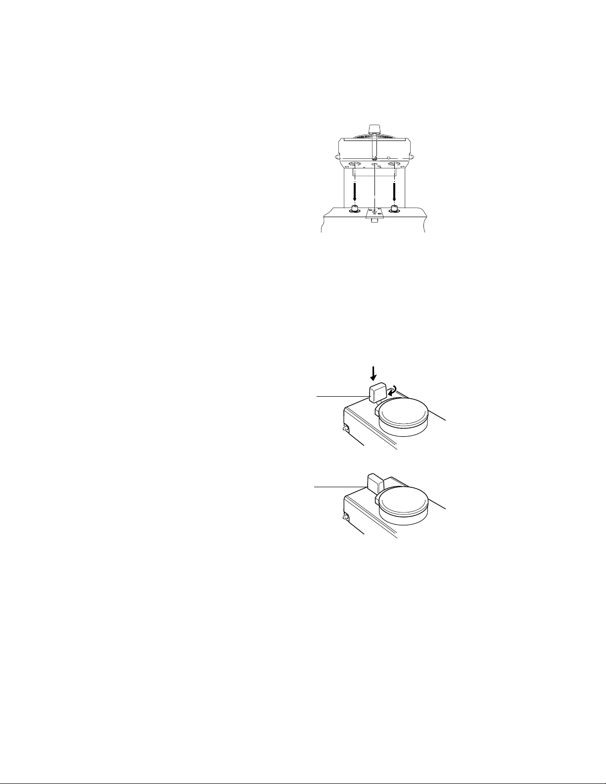
Step 4
Install the vaporizer onto the manifold.
• Hold the main body of the
vaporizer in an upright position
with both hands
• Lower the vaporizer onto the
manifold, ensuring that the
vaporizer interlock block ports
engage correctly with the
manifold port valves.
.
ww
ww
CAUTION Push the locking lever all the way down before turning it. The mechanism
3 Setup and Mounting Procedure
AB80018
Figure 3-4 • Installing the vaporizer
can be damaged if an attempt is made to turn the lever before it is
pushed all the way down.
Step 5
Lock the vaporizer onto the manifold.
• Push the locking lever all the way
down.
• Turn it clockwise to the locked
position to lock the vaporizer
onto the manifold.
Step 6
Ensure that the vaporizer is correctly
mounted (see instructions on the next
page).
1
1
AB80004
1. Locking lever
Figure 3-5 • Locking the vaporizer onto a manifold
1175-0013-000
3-3
Tec 7 Vaporizer
Checking the vaporizer for correct mounting
ww
ww
WARNING To help ensure correct operation, do not use a vaporizer that is either
visibly out of line on the manifold or that can be lifted off the manifold
when the locking lever is in the locked position.
If more than one vaporizer is fitted, visually check to make sure that the tops of the
vaporizers are level. If the vaporizer is visibly out of line, perform steps 2 and 3 as
described in Removing the vaporizer from a manifold and remount it correctly.
When the vaporizer appears to be level and the locking lever is in the locked position,
attempt to lift the vaporizer straight up from the manifold. If the vaporizer can be lifted
off the manifold, it is not correctly mounted. Remount the vaporizer (see Vaporizer
mounting procedure ).
Verify that the interlock rods are in alignment by making sure that only one vaporizer at
a time can be turned ON.
Check the anesthesia system for leaks in accordance with the relevant User’s
Reference Manual with the vaporizer dial turned to 0% and then repeat the check with
the vaporizer dial turned to .
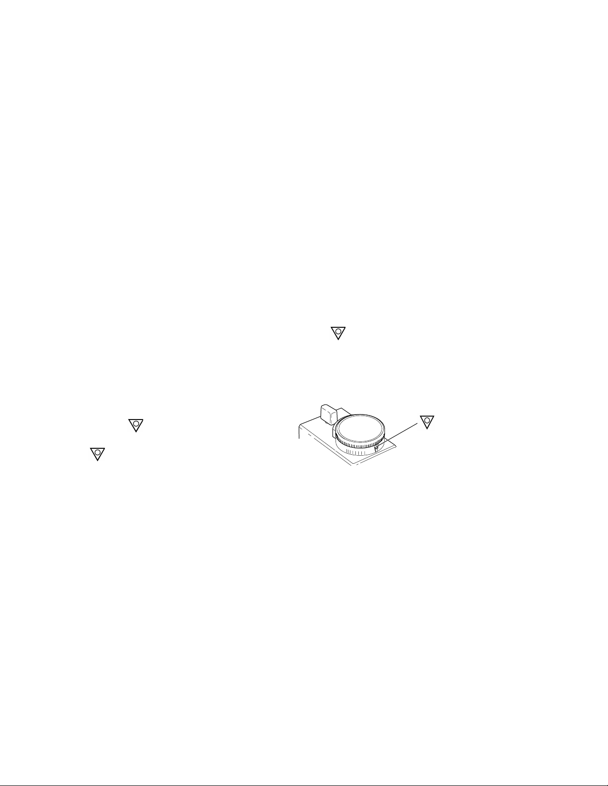
Removing the vaporizer from a manifold
Step 1
Set the dial to .
If the dial is not completely turned to
OFF
the position the vaporizer cannot
be released from the manifold.
OFF
Figure 3-6 • Setting the dial
n
e
b
Å
AB80001
3-4
1175-0013-000

Step 2
Unlock the locking lever.
• Turn the locking lever counterclockwise.
• Release the locking lever and
check that the locking lever
springs up to the unlocked
position to release the vaporizer
from the manifold.
3 Setup and Mounting Procedure
Locked
1
2
Unlocked
1. Locking lever
2. Dial
Figure 3-7 • Unlocking the locking lever
1
2
AB80003
Step 3
Carefully lift the vaporizer up from the
manifold.
AB80019
Figure 3-8 • Lifting the vaporizer
1175-0013-000
3-5
Loading...