


 Loading...
MRI Monitor
Technical Reference Manual
All specifications are subject to change without notice. CAUTION: U.S. Federal law restricts this device to sale by or on the order of a licensed medical practitioner.
Outside the USA, check local laws for any restriction that may apply.
|
Order Code M1079546 |
|
September, 2006 |
|
2nd edition |
Datex-Ohmeda Inc. |
GE Healthcare Finland Oy |
P.O. Box 7550 |
Helsinki, Finland |
Madison, WI 53707-7550, USA |
P.O. Box 900 |
Tel: +1 608 221 1551 |
FI-00031 GE, FINLAND |
Fax: +1 608 222 9147 |
Tel: +358 10 39411 |
|
Fax: +358 9 1463310 |
|
www.gehealthcare.com |
|
©2005, 2006 Copyright General Electric Company |
Intended purpose (Indications for use)
The MRI Monitor with L-CANE05 or L-CANE05A software, module options E-MRIPSN, E-MRICAiOV, E-MRICAiO, E-MRICO and accessories is indicated for monitoring of hemodynamic (comprising ECG (including heart rate, ST-segment and arrhythmia), NIBP, SpO2, and invasive blood pressure), respiratory (CO2, O2, N2O, anesthetic
agents, anesthetic agent identification, and respiration rate) and ventilatory (comprising airway pressure, volume and flow) status of hospital patients during magnetic resonance scanning.
The NIBP measurement is indicated for patients who weigh 5kg (11 lb) and up. The MRI Monitor with L-CANE05 or L-CANE05A software is also indicated for documenting patient care related information.
The MRI Monitor with L-CANE05 or L-CANE05A software, module options E-MRIPSN, E-MRICAiOV, E-MRICAiO, E-MRICO and accessories is indicated for use in the MR environment up to 300 Gauss with static magnets up to 3.0 Tesla. SpO2 and ECG monitoring is indicated only with accessories specifically designed for the MR
environment.
The MRI Monitor with L-CANE05 or L-CANE05A software is indicated for use by qualified medical personnel only.
Classifications
In accordance with IEC 60601-1
Class I and internally powered equipment – the type of protection against electric shock.
Type BF or CF equipment. The degree of protection against electric shock is indicated by a symbol on each parameter module.
Equipment not suitable for use in the presence of a flammable anesthetic mixture with air or with oxygen or nitrous oxide.
Continuous operation according to the mode of operation.
In accordance with IEC 60529
IPX1 - degree of protection against harmful ingress of water.
In accordance with EU Medical Device Directive
The MRI Monitor is classified as IIb.
In accordance with CISPR 11:
Group 1, Class B
•Group 1 contains all ISM (Industrial, scientific and medical) equipment in which there is intentionally generated and/or used conductively coupled radio-frequency energy which is necessary for the internal functioning of the equipment itself.
•Class B equipment is suitable for use in domestic establishments and in establishments directly connected to a low voltage power supply network which supplies buildings used for domestic purposes.
Responsibility of the manufacturer
GE Healthcare Finland Oy (GE) is responsible for the effects on safety, reliability and performance of the equipment only if:
•assembly, extensions, readjustments, modifications, servicing and repairs are carried out by personnel authorized by GE.
•the electrical installation of the monitor room complies with appropriate requirements.
•the equipment is used in accordance with the "User's Guide."
•manufacturer approved MRI Monitor system components are used.
Trademarks
Datex, Ohmeda, S/5, D-lite, D-lite+, Pedi-lite, Pedi-lite+, D-fend, D-fend+, Mini D-fend, OxyTip+, MemCard, ComWheel, ComBar, EarSat, FingerSat, FlexSat, PatientO2, Patient Spirometry, Entropy and Tonometrics are
trademarks of GE Healthcare Finland Oy. All other product and company names are property of their respective owners.

Master table of contents
MRI Monitor
Technical Reference Manual, Order code: M1079546 2nd edition
Part I, General Service Guide
Document No. |
Updated |
Description |
|
|
|
|
1 |
|
|
|
|
M1041746-2 |
|
Introduction, System description, Installation, |
|
|
|
Interfacing, Functional check, General troubleshooting |
|
|
|
|
2 |
M1041747-1 |
|
Planned Maintenance Instructions |
|
|
|
|
|
Part II, Product Service Guide
Document No. |
Updated |
Description |
|
|
|
|
1 |
|
|
|
|
M1056423 |
|
MRI Service Menu |
|
|
|
|
2 |
M1084164-1 |
|
MRI Shield N-MRI2 Rev. 01, incl. ECG measurement |
|
|
|
unit, Network option for MRI Monitor, N-MRINET, |
|
|
|
Active Remote Screen Option, N-MRIREMOTE |
|
|
|
Command Bar for MRI2, K-MRIANEB, |
|
|
|
LCD Display, D-LCC19-01, |
|
|
|
Remote screen and sound converter |
|
|
|
|
3 |
M1056422-2 |
|
MRI Monitor Frame F-MRICM1, Display Unit |
|
|
|
Software Licenses, L-CANE05, L-CANE05A |
|
|
|
MRI Monitor Frame F-MRICM1, Frame Unit, |
|
|
|
AC/DC Power Supply Unit |
|
|
|
Options N-CMMEM, N-CMW and N-MRIREC1 |
|
|
|
|
4 |
M1041750-1 |
|
Hemodynamic MRI Module, E-MRIPSN |
|
|
|
|
5 |
M1041752-2 |
|
Airway Gas Module, E-MRICAiOV |
|
|
|
|
6 |
M1027838-5 |
|
S/5 Remote Controller, K-CREMCO |
|
|
|
|
7 |
M1072254-1 |
|
Recordkeeping keyboard, K-ARKB |
|
|
|
|
8 |
M1056425-1 |
|
S/5 Device Interfacing Solution, N-DISVENT |
|
|
|
|
9 |
M1041753-2 |
|
Spare parts |
|
|
|
|
|


Table of contents
Table of contents
Table of contents |
|
i |
||
Table of figures |
|
iii |
||
List of tables |
|
|
iv |
|
About this manual |
|
1 |
||
1 |
Introduction |
|
3 |
|
|
1.1 |
System introduction . . . . . . . . . . . . . . . . . . . . . . . . . . . . . . . . . . . . . . . . . . . . . . . . . . . . . . . . . . . . . . . . . |
. . 3 |
|
|
|
1.1.1 |
MRI Monitor system components. . . . . . . . . . . . . . . . . . . . . . . . . . . . . . . . . . . . . . . . . . . . . . |
. . 3 |
|
|
1.1.2 |
Monitoring in MR room . . . . . . . . . . . . . . . . . . . . . . . . . . . . . . . . . . . . . . . . . . . . . . . . . . . . . . . |
. 4 |
|
|
1.1.3 |
Monitoring in control room . . . . . . . . . . . . . . . . . . . . . . . . . . . . . . . . . . . . . . . . . . . . . . . . . . . . |
. 5 |
|
|
1.1.4 |
MR monitoring in network . . . . . . . . . . . . . . . . . . . . . . . . . . . . . . . . . . . . . . . . . . . . . . . . . . . . . |
. 6 |
|
|
1.1.5 |
Monitoring in wireless network . . . . . . . . . . . . . . . . . . . . . . . . . . . . . . . . . . . . . . . . . . . . . . . . . |
. 7 |
|
1.2 |
MRI Monitor introduction . . . . . . . . . . . . . . . . . . . . . . . . . . . . . . . . . . . . . . . . . . . . . . . . . . . . . . . . . . . . . . |
. 8 |
|
|
|
1.2.1 |
MRI Monitor parts and connections . . . . . . . . . . . . . . . . . . . . . . . . . . . . . . . . . . . . . . . . . . . . . |
. 8 |
|
|
1.2.2 |
MRI Monitor frame options and modules . . . . . . . . . . . . . . . . . . . . . . . . . . . . . . . . . . . . . . . . |
. 9 |
|
|
1.2.3 |
Connector panel . . . . . . . . . . . . . . . . . . . . . . . . . . . . . . . . . . . . . . . . . . . . . . . . . . . . . . . . . . . . |
. 9 |
|
|
1.2.4 |
MRI Cart . . . . . . . . . . . . . . . . . . . . . . . . . . . . . . . . . . . . . . . . . . . . . . . . . . . . . . . . . . . . . . . . . . . |
10 |
|
1.3 |
Symbols. |
. . . . . . . . . . . . . . . . . . . . . . . . . . . . . . . . . . . . . . . . . . . . . . . . . . . . . . . . . . . . . . . . . . . . . . . . . . . |
11 |
|
|
1.3.1 |
Symbols on transport packaging . . . . . . . . . . . . . . . . . . . . . . . . . . . . . . . . . . . . . . . . . . . . . . . |
11 |
|
|
1.3.2 |
Symbols on equipment . . . . . . . . . . . . . . . . . . . . . . . . . . . . . . . . . . . . . . . . . . . . . . . . . . . . . . . |
11 |
|
|
1.3.3 |
Equipment safety symbols . . . . . . . . . . . . . . . . . . . . . . . . . . . . . . . . . . . . . . . . . . . . . . . . . . . . |
11 |
|
|
1.3.4 |
Other symbols . . . . . . . . . . . . . . . . . . . . . . . . . . . . . . . . . . . . . . . . . . . . . . . . . . . . . . . . . . . . . . |
12 |
|
1.4 |
Safety . . |
. . . . . . . . . . . . . . . . . . . . . . . . . . . . . . . . . . . . . . . . . . . . . . . . . . . . . . . . . . . . . . . . . . . . . . . . . . . |
15 |
|
|
1.4.1 |
Safety precautions. . . . . . . . . . . . . . . . . . . . . . . . . . . . . . . . . . . . . . . . . . . . . . . . . . . . . . . . . . . |
15 |
|
|
1.4.2 |
ESD precautionary procedures. . . . . . . . . . . . . . . . . . . . . . . . . . . . . . . . . . . . . . . . . . . . . . . . . |
19 |
|
|
1.4.3 |
Disposal . . . . . . . . . . . . . . . . . . . . . . . . . . . . . . . . . . . . . . . . . . . . . . . . . . . . . . . . . . . . . . . . . . . |
19 |
2 |
System description |
20 |
||
|
2.1 |
Introduction. . . . . . . . . . . . . . . . . . . . . . . . . . . . . . . . . . . . . . . . . . . . . . . . . . . . . . . . . . . . . . . . . . . . . . . . . |
20 |
|
|
2.2 |
Bus structure. . . . . . . . . . . . . . . . . . . . . . . . . . . . . . . . . . . . . . . . . . . . . . . . . . . . . . . . . . . . . . . . . . . . . . . . |
20 |
|
|
2.3 |
Distributed processing . . . . . . . . . . . . . . . . . . . . . . . . . . . . . . . . . . . . . . . . . . . . . . . . . . . . . . . . . . . . . . . . |
21 |
|
|
2.4 |
Module communication . . . . . . . . . . . . . . . . . . . . . . . . . . . . . . . . . . . . . . . . . . . . . . . . . . . . . . . . . . . . . . . |
21 |
|
|
2.5 |
Software loading. . . . . . . . . . . . . . . . . . . . . . . . . . . . . . . . . . . . . . . . . . . . . . . . . . . . . . . . . . . . . . . . . . . . . |
22 |
|
|
2.6 |
Parameter modules . . . . . . . . . . . . . . . . . . . . . . . . . . . . . . . . . . . . . . . . . . . . . . . . . . . . . . . . . . . . . . . . . . |
22 |
|
|
2.7 |
High magnetic field alarm . . . . . . . . . . . . . . . . . . . . . . . . . . . . . . . . . . . . . . . . . . . . . . . . . . . . . . . . . . . . . |
23 |
|
3 |
System installation |
24 |
||
|
3.1 |
Unpacking instructions . . . . . . . . . . . . . . . . . . . . . . . . . . . . . . . . . . . . . . . . . . . . . . . . . . . . . . . . . . . . . . . |
24 |
|
|
3.2 |
Choosing location. . . . . . . . . . . . . . . . . . . . . . . . . . . . . . . . . . . . . . . . . . . . . . . . . . . . . . . . . . . . . . . . . . . . |
24 |
|
|
3.3 |
Installing and mounting the monitor . . . . . . . . . . . . . . . . . . . . . . . . . . . . . . . . . . . . . . . . . . . . . . . . . . . . . |
25 |
|
|
|
3.3.1 |
MRI Monitor parts and connections . . . . . . . . . . . . . . . . . . . . . . . . . . . . . . . . . . . . . . . . . . . . . |
27 |
|
|
3.3.2 |
Monitor distance from the magnet bore. . . . . . . . . . . . . . . . . . . . . . . . . . . . . . . . . . . . . . . . . . |
28 |
|
|
3.3.3 |
Connecting to mains . . . . . . . . . . . . . . . . . . . . . . . . . . . . . . . . . . . . . . . . . . . . . . . . . . . . . . . . . |
28 |
|
|
3.3.4 |
Mounting the MRI Monitor to MRI Cart. . . . . . . . . . . . . . . . . . . . . . . . . . . . . . . . . . . . . . . . . . . |
29 |
i
Document no. M1041746 -1

MRI Monitor
3.3.5 Connecting to Datex-Ohmeda Network . . . . . . . . . . . . . . . . . . . . . . . . . . . . . . . . . . . . . . . . . .31 3.3.6 Connecting to Wireless LAN network . . . . . . . . . . . . . . . . . . . . . . . . . . . . . . . . . . . . . . . . . . . .33 3.3.7 Device Interfacing Solution, N-DISVENT . . . . . . . . . . . . . . . . . . . . . . . . . . . . . . . . . . . . . . . . .34 3.3.8 Remote Screen installation. . . . . . . . . . . . . . . . . . . . . . . . . . . . . . . . . . . . . . . . . . . . . . . . . . . .35 3.3.9 Parameter modules . . . . . . . . . . . . . . . . . . . . . . . . . . . . . . . . . . . . . . . . . . . . . . . . . . . . . . . . . .37 3.3.10 Downloading Monitor Software . . . . . . . . . . . . . . . . . . . . . . . . . . . . . . . . . . . . . . . . . . . . . . . .38 3.3.11 Performing Factory Reset . . . . . . . . . . . . . . . . . . . . . . . . . . . . . . . . . . . . . . . . . . . . . . . . . . . . .39 3.3.12 Performing Service Reset . . . . . . . . . . . . . . . . . . . . . . . . . . . . . . . . . . . . . . . . . . . . . . . . . . . . .39
3.4 S/5 Remote Controller, K-REMCO . . . . . . . . . . . . . . . . . . . . . . . . . . . . . . . . . . . . . . . . . . . . . . . . . . . . . .40 3.5 Anesthesia Record Keeping Keyboard, K-ARKB . . . . . . . . . . . . . . . . . . . . . . . . . . . . . . . . . . . . . . . . . . .40 3.5.1 Connection to MRI Monitor . . . . . . . . . . . . . . . . . . . . . . . . . . . . . . . . . . . . . . . . . . . . . . . . . . . .40 3.6 MRI Airway Module gas scavenging . . . . . . . . . . . . . . . . . . . . . . . . . . . . . . . . . . . . . . . . . . . . . . . . . . . . .40 3.6.1 Sample gas exhaust . . . . . . . . . . . . . . . . . . . . . . . . . . . . . . . . . . . . . . . . . . . . . . . . . . . . . . . . .40
3.7 Troubleshooting . . . . . . . . . . . . . . . . . . . . . . . . . . . . . . . . . . . . . . . . . . . . . . . . . . . . . . . . . . . . . . . . . . . . .42
4 |
Interfacing |
|
43 |
|
|
4.1 |
Interfaced parameters . . . . . . . . . . . . . . . . . . . . . . . . . . . . . . . . . . . . . . . . . . . . . . . . . . . . . . . . . . . . . . . |
.43 |
|
|
4.2 |
Interfacing external bedside devices via Device Interfacing Solutions, N-DISxxx . . . . . . . . . . . . . . . . |
.43 |
|
|
|
4.2.1 |
Device Interfacing Solution components. . . . . . . . . . . . . . . . . . . . . . . . . . . . . . . . . . . . . . . . |
.43 |
|
|
4.2.2 |
Connections . . . . . . . . . . . . . . . . . . . . . . . . . . . . . . . . . . . . . . . . . . . . . . . . . . . . . . . . . . . . . . . . |
43 |
|
|
4.2.3 |
Mounting . . . . . . . . . . . . . . . . . . . . . . . . . . . . . . . . . . . . . . . . . . . . . . . . . . . . . . . . . . . . . . . . . . |
44 |
|
|
4.2.4 |
Selecting the external device . . . . . . . . . . . . . . . . . . . . . . . . . . . . . . . . . . . . . . . . . . . . . . . . . . |
45 |
|
|
4.2.5 |
Functional check . . . . . . . . . . . . . . . . . . . . . . . . . . . . . . . . . . . . . . . . . . . . . . . . . . . . . . . . . . . . |
45 |
|
|
4.2.6 |
Selecting the parameter data source. . . . . . . . . . . . . . . . . . . . . . . . . . . . . . . . . . . . . . . . . . . . |
46 |
|
4.3 |
Interfacing printer . . . . . . . . . . . . . . . . . . . . . . . . . . . . . . . . . . . . . . . . . . . . . . . . . . . . . . . . . . . . . . . . . . . . |
46 |
|
|
4.4 |
Interfacing computer . . . . . . . . . . . . . . . . . . . . . . . . . . . . . . . . . . . . . . . . . . . . . . . . . . . . . . . . . . . . . . . . . |
47 |
|
|
4.5 |
Output signals. . . . . . . . . . . . . . . . . . . . . . . . . . . . . . . . . . . . . . . . . . . . . . . . . . . . . . . . . . . . . . . . . . . . . . . |
47 |
|
5 |
Functional check |
48 |
|
|
5.1 |
Recommended tools . . . . . . . . . . . . . . . . . . . . . . . . . . . . . . . . . . . . . . . . . . . . . . . . . . . . . . . . . . . . . . . |
. .48 |
|
5.2 |
Visual inspection . . . . . . . . . . . . . . . . . . . . . . . . . . . . . . . . . . . . . . . . . . . . . . . . . . . . . . . . . . . . . . . . . . |
. .49 |
|
5.3 |
Functional inspection. . . . . . . . . . . . . . . . . . . . . . . . . . . . . . . . . . . . . . . . . . . . . . . . . . . . . . . . . . . . . . . . |
.50 |
6 |
General troubleshooting |
55 |
|
Appendix A: Functional check form, MRI Monitor |
A-1 |
||
Appendix B: |
1ElectroMagnetic Compatibility |
B-1 |
|
ii
Document no. M1041746 -1

Table of figures
Table of figures
Figure 1 |
MRI monitoring system components in MR room ................................................................................... |
4 |
Figure 2 |
MRI monitoring system components when using Active Remote Screen.................................................. |
5 |
Figure 3 |
MR monitoring in network ..................................................................................................................... |
6 |
Figure 4 |
MRI monitoring in wireless network ....................................................................................................... |
7 |
Figure 5 |
MRI Monitor parts and connections....................................................................................................... |
8 |
Figure 6 |
MRI Cart............................................................................................................................................. |
10 |
Figure 7 |
General bus structure of MRI Monitor .................................................................................................. |
20 |
Figure 8 |
Principle of UPI section operation........................................................................................................ |
21 |
Figure 9 |
General structure of parameter modules with patient isolation ............................................................. |
22 |
Figure 10 |
Example of 300 Gauss line distance with a MR scanner. ...................................................................... |
25 |
Figure 11 |
MRI Monitor parts and connections..................................................................................................... |
27 |
Figure 12 |
Field strength in MR room ................................................................................................................... |
28 |
Figure 13 |
MRI Cart............................................................................................................................................. |
29 |
Figure 14 |
‘Do not place any non-MR compatible items’ symbol ........................................................................... |
30 |
Figure 15 |
MRI Monitor connected to network ...................................................................................................... |
31 |
Figure 16 |
WLAN Acces Point in Control room ...................................................................................................... |
33 |
Figure 17 |
MRI Monitor connected to wireless network ......................................................................................... |
34 |
Figure 18 |
Control room installation .................................................................................................................... |
35 |
Figure 19 |
Exhaust to reservoir tube..................................................................................................................... |
41 |
Figure 20 |
Connection cables and LED indicators ................................................................................................ |
44 |
Figure 21 |
An example of interfacing external devices with Device Interfacing Solution .......................................... |
45 |
Figure 22 |
MRI general troubleshooting flowchart ................................................................................................ |
56 |
iii
Document no. M1041746 -1

MRI Monitor
List of tables |
|
|
Table 1 |
Guidance and manufacturer’s declaration – electromagnetic emissions ................................... |
1 |
Table 2 |
Guidance and manufacturer’s declaration – electromagnetic immunity .................................... |
2 |
Table 3 |
Guidance and manufacturer’s declaration – electromagnetic immunity .................................... |
3 |
Table 4 |
Recommended separation distances between portable and mobile RF communications equip- |
|
ment and the MRI Monitor......................................................................................................................... |
5 |
|
iv
Document no. M1041746 -1

About this manual
Intended audience
This Technical reference manual is meant for service representatives and technical personnel who install, configure, maintain, administer, troubleshoot or repair MRI Monitor running the software license L-CANE05 or L-CANE05A.
Notes to the reader
As the monitor setup may vary, some functions described may not be available in the monitor you are using.
•The order code for the manual is M1079546. This is the second edition.
•Part I gives the reader an overview of the MRI Monitor. It contains the information needed to install, interface and troubleshoot the monitors. Instructions for functional check and planned maintenance are also included. Read the manual through and make sure that you understand the procedures described before the installation of the monitor. To avoid risks concerning safety or health, strictly observe the warning indications. If you need any assistance concerning the installation, please do not hesitate to contact your authorized distributor.
•Part II contains detailed descriptions of each component of the MRI Monitor system, such as MRI Monitor frame, shield, parameter modules and Active Remote Screen. Service check for each product, service menus and all the spare parts information for MRI Monitor is included.
The manufacturer reserves the right to change product specifications without prior notice. Although the information in this manual is believed to be accurate and reliable, the manufacturer assumes no responsibility for its use.
Installation and service are allowed by authorized service personnel only.
GE Healthcare Finland Oy (GE) assumes no responsibility for the use or reliability of its software in equipment that is not furnished by GE.
Related documentation
For instructions for daily use including cleaning and daily maintenance, clinical aspects and basic methods of measurement see:
MRI Monitor, User’s Guide
MRI Monitor, User’s Reference Manual
For more information about the iCentral and anesthesia record keeping solution, see the “Technical Reference Manuals” and “User’s Reference Manuals” for these products.
Software options and default settings are described in the “Default Configuration Worksheet” delivered with each monitor.
Available accessories are described in the User’s Guide in “MRI accessories” section.
Conventions used
To help you find and interpret information easily, the manual uses consistent text formats:
"Sign the check form after performing the procedure.
1
Document no. M1041746 -1

MRI Monitor
Hard Keys |
Names of the hard keys on the Remote Controller, Command Board, Active Remote Screen |
|
Command Bar and side panel are written in the following way: Others. |
Menu Items |
Software terms that identify window parts or menu items are written in bold italic: ECG Setup. |
|
Menu access is described from top to bottom. For example, the selection of the Monitor Setup hard |
|
key, the Screen 1 Setup menu item and the Waveform Fields menu item would be shown as |
|
Monitor Setup - Screen 1 Setup - Waveform Fields. |
‘Messages’ |
Messages (alarm messages, informative messages) displayed on the screen are written inside single |
|
quotes: ‘Please wait’. |
“Sections” |
When referring to different sections in this manual or to other manuals, manual names and section |
|
names are enclosed in double quotes: |
|
See section "Cleaning and care." |
|
Please refer to "iCentral User's Reference Manual: Alarms." |
Hypertext links |
Hypertext links on PDF versions are written in blue color. |
WARNING |
Warnings are written in the following way: |
WARNING |
This is a WARNING. |
CAUTION |
Cautions are written in the following way: |
CAUTION |
This is a CAUTION. |
NOTE |
Notes are written in the following way: |
|
NOTE: This is a NOTE. |
|
In this manual, the word “select” means choosing and confirming. |
Illustrations and names
All illustrations in this manual are only examples, and may not necessarily reflect your system settings or data displayed in your system. If a particular selection is not available in your system, the selection is shown grayed.
In this manual, the concept MRI Monitor always refers to the MRI Monitor labeled as N-MRI2.
2
Document no. M1041746 -1
Introduction
1 Introduction
1.1System introduction
The MRI Monitor is a modular multiparameter patient monitor. The monitor is especially designed for multiparameter patient monitoring in MR environment. It can also be used during transportation within the hospital, for example, when transporting the patient from induction to the MR environment.
The modular design makes the system flexible and easy to upgrade. In addition to patient parameter modularity and easy upgrades, the monitor can be upgraded to anesthesia record keeping, wired and wireless networking and memory card operation. Your system may also include Active Remote Screen allowing full remote control over the MRI Monitor. Additionally, external devices can be interfaced to the monitor with interface modules.
NOTE: Your system may not include all these components. Consult your local representative for the available components.
1.1.1MRI Monitor system components
Options for the MRI Monitor system
−Built-in recorder, N-CMREC1
−Wireless network option, N-CMW
−Active Remote Screen, N-MRIRemote (includes a fiber optic cable and Remote screen converter)
−Network option, N-MRINET (includes a fiber optic Network cable and a fiber optic converter board, B-FOC)
Possible software options for the MRI Monitor
−MemCard option, N-CMMEM
MRI Monitor frame options
−N-SN (for ECG, SpO2, NIBP)
−N-PSN (for ECG, SpO2, NIBP, InvBP)
−N-PSNG (for ECG, SpO2, NIBP, InvBP, CO2, Patient O2 and N2O)
−N-SNG (for ECG, SpO2, NIBP, CO2, Patient O2 and N2O)
−N-PSNGV (for ECG, SpO2, NIBP, InvBP, CO2, Patient O2, N2O, anesthetic agents, agent identification and patient spirometry)
−N-SNGV (for ECG, SpO2, NIBP, InvBP, CO2, Patient O2, N2O, anesthetic agents, agent identification and patient spirometry)
MR compatible modules
−Hemodynamic MRI Module E-MRIPSN
−MRI Compact Airway Modules E-MRICO, E-MRICAiO and E-MRICAiOV
Active Remote Screen display option with built-in loudspeakers
−19" LCD display, D-LCC19 - 01
3
Document no. M1041746 -1
MRI Monitor
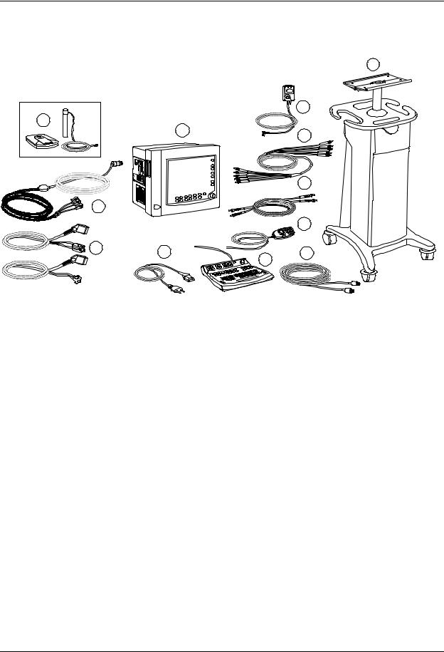
1.1.2Monitoring in MR room
The MRI Monitor system in the MR room may consist of the elements shown in the picture below.
2
3
12
1 |
4 |
|
|
|
5 |
11 |
|
|
|
|
6 |
10 |
9 |
7 |
|
||
|
|
8 |
|
Figure 1 |
MRI monitoring system components in MR room |
||
(1) |
MRI Monitor with MR compatible modules inside |
(8) |
Anesthesia record keeping keyboard |
|
(2) |
MRI Cart. You can also use a wall mount. |
(9) |
Mains power cable |
|
(3) |
Device Interfacing Solution, DIS |
(10) |
MR-specific SpO2 accessories (OXY-FMR, OXY-WMR) |
|
(4) |
Active Remote Screen fiber optic cable |
(11) |
MR-specific ECG cable |
|
(5) |
Fiber optic network cable |
|
(12) |
Datex-Ohmeda Wireless Network (WLAN) Access |
(6) |
Remote Controller, K-CREMCO |
|
Point, N-WAP, and WLAN antenna |
|
(7) |
MR scanner specific cardiac gating cable |
|
|
|
4
Document no. M1041746 -1
Introduction
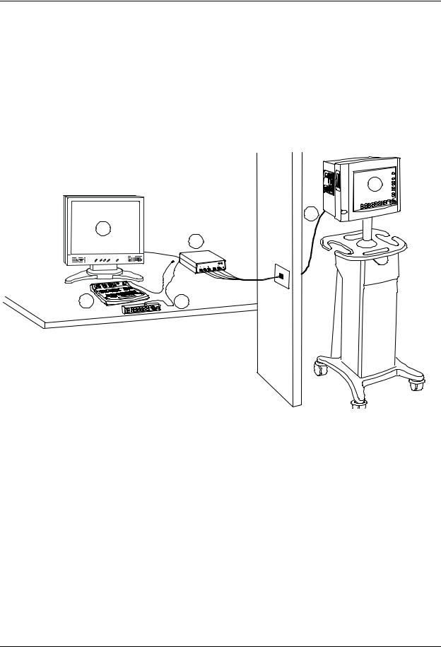
1.1.3Monitoring in control room
Active Remote Screen is an external surveillance monitor for MRI Monitor. While the MRI Monitor is placed inside the MR examination room, the Active Remote Screen is used outside the MR environment in the control room to monitor the patient. The connection between the MRI Monitor and Active Remote Screen is done over on fiber optic cable, which ensures safe and undisturbed data transmission. The Active Remote Screen has the same functionality as the MRI Monitor and it allows full remote control over the MRI Monitor. However, the MRI Monitor can not be turned on or to standby through the Active Remote Screen.
The possible components are described below.
4
3
1
2
6 |
5 |
Figure 2 MRI monitoring system components when using Active Remote Screen
(1)Active Remote Screen with built-in loudspeakers.
(2)Remote screen converter. Contains connectors for Active Remote Screen and anesthesia record keeping keyboard or Command Bar K-MRIANEB.
(3)Fiber optic cable
(4)MRI Monitor
(5)Command Bar
(6)Anesthesia record keeping keyboard K-ARKB
5
Document no. M1041746 -1
MRI Monitor
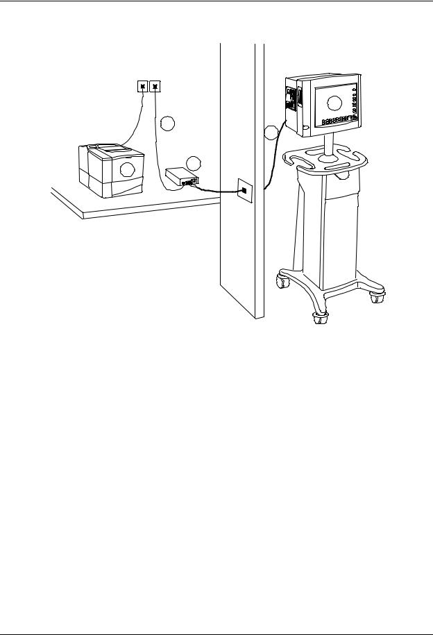
1.1.4MR monitoring in network
1
5
2
3
4
Figure 3 MR monitoring in network
(1)MRI Monitor
(2)Fiber optic Network cable
(3)Fiber optic converter, N-FOC, which connects the monitor to the Datex-Ohmeda Network (wired or wireless)
(4)Network printer
(5)Monitor-Network cable
Communication between monitors
You can use the MRI Monitor as a stand-alone monitor or for
−viewing and receiving data (alarms, vital signs) from other patient monitors
−gathering and storing data during intrahospital transportation.
To view other patient monitors, the monitor needs to be connected to network. To gather, store, and transfer data between different monitors, use the Data Card or network communication.
NOTE: You cannot transfer data to the MRI Monitor from the Data Card; use network for this purpose. The Data Card is for storage and transfer of patient data from the MRI Monitor. The Menu Card is used for storing the anesthesia record keeping menus and configurations, and for loading and storing user modes.
6
Document no. M1041746 -1
Introduction
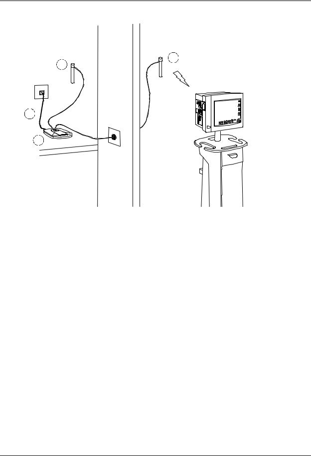
1.1.5Monitoring in wireless network
1
1
2
3
Figure 4 MRI monitoring in wireless network
(1)Antennas
(2)Network cable
(3)Access point.
NOTE: Before installing the wireless monitoring network in the MR environment, the system must be tested to avoid all the interference that it may cause to the MR pictures.
7
Document no. M1041746 -1

MRI Monitor
1.2MRI Monitor introduction
1.2.1MRI Monitor parts and connections
4 |
3 |
2 |
1 |
5 |
|
|
|
6 |
|
|
13 |
7 |
|
|
|
8 |
|
|
14 |
|
|
|
9
10
11
12
23
24
Figure 5 MRI Monitor parts and connections
15
16
17
18
19
20
 21
21
22
(1) |
Frame for MRI Monitor, F-MRICM1 |
(13) |
Air filter |
(2) |
MRI Shield for MRI Monitor, N-MRI2 |
(14) |
Recorder, N-CMREC1 |
(3) |
Hemodynamic MRI module, E- MRIPSN |
(15) |
Connectors for Active Remote Screen |
(4) |
Slot for memory cards (PCMCIA) |
(16) |
Connector for Device Interfacing Solution, DIS |
(5) |
D-fend |
(17) |
Cardiac (ECG) gating connector |
(6) |
Spirometry connectors |
(18) |
Network connectors |
(7) |
NIBP connector |
(19) |
Mains power inlet |
(8) |
ECG connector |
(20) |
Connector for anesthesia record keeping keyboard |
(9) |
InvBP connector |
|
or K-CREMCO |
(10) |
SpO2 connector |
(21) |
Side panel keys |
(11) |
Air filter |
(22) |
ComWheel |
(12) |
MRI Compact Airway Module E-MRICxx |
(23) |
Command Board |
|
|
(24) |
High magnetic field alarm led |
8
Document no. M1041746 -1

Introduction
1.2.2MRI Monitor frame options and modules
The MRI Monitor has the following frame and module options available.
Parameter |
Frame options and modules |
|
|
|
|
ECG, SpO2 and NIBP |
• N-SN, N-SNG, N-SNGV, N-PSN, N-PSNG or N-PSNGV |
|
• E-MRIPSN module |
|
|
InvBP (up to 2) |
• N-PSN, N-PSNG or N-PSNGV |
|
• E-MRIPSN module |
|
|
CO2, Patient O2 and N2O |
• N-PSNG, N-SNG, N-PSNGV or N-SNGV |
|
• E-MRICO, E-MRICAiO or E-MRICAiOV |
|
|
Anesthetic agents, agent identification |
• N-PSNG, N-SNG, N-PSNGV or N-SNGV |
|
• E-MRICAiO or E-MRICAiOV |
|
|
Spirometry |
• N-PSNGV or N-SNGV |
|
• E-MRICAiOV |
|
|
−Hemodynamic MRI Module E-MRIPSN measures ECG, SpO2, NIBP and InvBP (two pressures, optional).
−MRI Compact Airway Modules E-MRICO, E-MRICAiO and E-MRICAiOV measure CO2 (C), O2 (O), Spirometry (V), anesthetic agents (A) and agent identification (i).
NOTE: The modules are preinstalled inside the shield and they can only be changed by authorized service personnel.
1.2.3Connector panel
The connectors for the different parameter accessories are located on the connector panel on the left side of the shield. The frame option determines the connectors included in the panel. Below is an example of the connector panel in the frame option N-PSNGV.
1 2
(1) Spirometry connectors (optional)
(2) D-Fend with sampling line connector (optional)
(3) ECG connector
(4) NIBP connector
(5) InvBP connector (optional)
(6) SpO2 connector
3 4 5 6
9
Document no. M1041746 -1
MRI Monitor
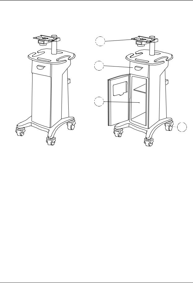
1.2.4MRI Cart
MRI Cart has been designed for MR environment. It allows you to move the monitor around the MR room, if necessary.
1
2
3
4
Figure 6 |
MRI Cart |
(1)Mounting plate for the MRI Monitor
(2)Drawer for small MR compatible accessories
NOTE: The maximum load of the MRI Cart drawer is 400 g (0.9 lb).
(3)Compartment for the manuals
(4)Caster brakes
NOTE: The maximum load of the MRI Cart monitor arm is 25 kg (55.12 lb).
10
Document no. M1041746 -1
Introduction
1.3Symbols
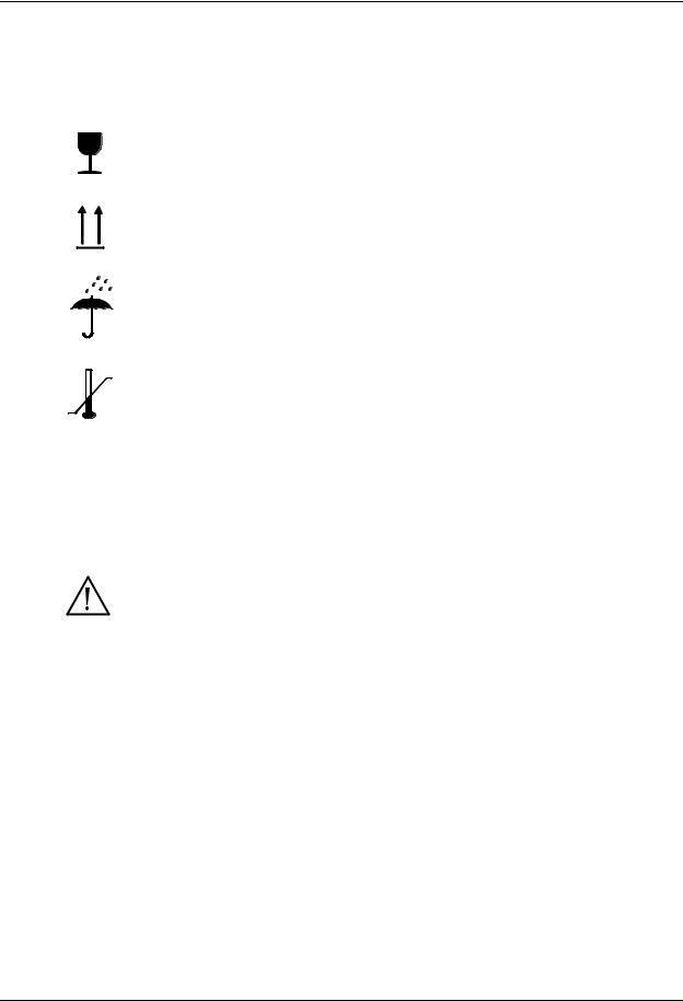
1.3.1Symbols on transport packaging
The contents of the transport package are fragile and must be handled with care.
Indicates the correct upright position of the transport package.
The transport package must be kept in a dry environment.
Indicates the temperature limitations within which the transport package should be stored.
1.3.2Symbols on equipment
1.3.3Equipment safety symbols
-Attention, consult accompanying documents.
-When displayed next to the O2 value, indicates that the FiO2 low alarm limit is set
below 21%.
-On the connector panel this symbol indicates that for pulse oximetry (SpO2) and invasive pressures (P1-P2), the patient isolation and protection against cardiac
defibrillator discharge are based on the SpO2 and invasive blood pressure accessories.
-On the rear panel this symbol indicates the following warnings and cautions:
*Electric shock hazard. Do not open the cover or the back. Refer servicing to qualified service personnel.
*For continued protection against fire hazard, replace the fuse only with one of the same type and rating.
*Do not touch a battery-operated monitor during defibrillation procedure.
*Disconnect from the power supply before servicing.
*Do not use the monitor without manufacturer approved mounting attached.
*Lithium battery on the CPU board: follow the regional regulations for disposal.
11
Document no. M1041746 -1

MRI Monitor
Type BF (IEC 60601-1) protection against electric shock.
Type BF (IEC 60601-1) defibrillator-proof protection against electric shock.
Type CF (IEC 60601-1) defibrillator-proof protection against electric shock.
When displayed in the upper left corner of the screen, indicates that the alarms are silenced. When displayed in the menu or digit fields, indicates that the alarm source has been turned off or alarm does not meet the alarm-specific activation criteria.
ESD warning symbol for electrostatic sensitive devices. Pins of connectors identified with the ESD warning symbol should not be touched. Connections should not be made to these connectors unless ESD precautionary procedures are used. For details, see section “1.4.2. ESD precautionary procedures”.
Symbol for non-ionizing electromagnetic radiation. Interference may occur in the vicinity of equipment marked with this symbol.
Symbol on the led on the front panel of the shield. The led indicates if the magnetic field is too strong.
Symbol on the MRI Cart drawer cover. Do not place any non-MR-compatible items in the MRI Cart.
1.3.4Other symbols
Equipotentiality. Monitor can be connected to potential equalization conductor.
Alternating current
Fuse. Replace the fuse only with one of the same type and rating.
12
Document no. M1041746 -1
Introduction
SN, S/N |
Serial Number |
|
|
|
Battery operation and remaining capacity (green bar) |
|
Battery charging (white bar) |
|
Submenu. Selecting an alternative marked with this symbol in a menu opens a new |
|
menu. |
|
The monitor is connected to the Datex-Ohmeda Network (LAN). |
|
The monitor is connected to the Datex-Ohmeda Network (WLAN). |
|
Data Card (green) and/or Menu Card (white) is inserted. |
|
WLAN signal strength. The number of segments corresponds to the signal strength: |
|
four segments indicate strong signal, one segment weak signal. When connection to |
|
access point is being searched, the segments scroll from zero to four and back. |
|
A blinking heart next to the heart rate or pulse rate value indicates the beats |
|
detected. |
|
Do not reuse. |
|
Use by. Indicates the last use day. |
|
Date of manufacturer |
|
Does not contain Latex. |
13
Document no. M1041746 -1

MRI Monitor
|
Do not immerse the sensor in liquids. |
IPX class: |
Degree of protection against harmful ingress of water as detailed in the |
|
IEC 60529: |
IPX0 |
- Ordinary equipment |
IPX1 |
- Protection against vertically falling water drops. |
IPX2 |
- Protection against vertically falling water drops when enclosure tilted up to 15 °. |
IPX3 |
- Protected against spraying water. |
IPX4 |
- Protected against splashing water. |
IPX7 |
- Protected against the effects of temporary immersion in water. |
IPX8 |
- Protected against the effects of continuous immersion in water. |
|
This symbol indicates that the waste of electrical and electronic equipment must not |
|
be disposed as unsorted municipal waste and must be collected separately. Please |
|
contact an authorized representative of the manufacturer for information concerning |
|
the decommissioning of your equipment. |
14
Document no. M1041746 -1

Introduction
1.4Safety
The following list contains general warnings and cautions you should know before installing, maintaining or servicing the system. Warnings and cautions specific to the use of the system can be found in the User’s Guide and User’s Reference Manual.
1.4.1 Safety precautions
Warnings |
|
WARNING |
A WARNING indicates a situation in which the user or the patient may be in |
|
danger of injury or death. |
Power connection
•Use only hospital-grade grounded power outlets and power cord. Do not remove the grounding pin from the power plug.
•The Active Remote Screen and printer must be supplied from an additional transformer providing at least basic isolation (isolating or separating transformer).
•Use only an intact power cord. Replace the power cord if it is cracked, frayed, broken or otherwise damaged.
•Do not apply tension to the power cord otherwise the cord may get damaged.
•Do not use an additional multiple socket outlet, extension cord or adapters of any kind.
•Before starting to use the system, ensure that the whole combination complies with the international standard IEC 60601-1-1 and with the requirements of the local authorities. Do not connect any external devices to the system other than those specified.
•If the integrity of the external protective earth conductor arrangement is in doubt, use the monitor with battery operation.
•To avoid the risk of electric shock, this equipment must only be connected to a supply mains with protective earth.
Installation
•The monitor contains some ferromagnetic material.
•Do not install or use the monitor inside the 300 Gauss line. Verify the 300 G line from the safety instructions of the MRI imaging equipment.
•Inside the 300 G line the monitor is subject to the attraction of the magnetic field.
•The MRI Monitor has been designed for MR environment. The MR scanners, however, may be capable of causing injury if the given instructions are not followed, especially with respect to electrically conducting lead positioning and safety distance from the magnet.
•The MRI Monitor has been designed to tolerate high magnetic field strengths over short-term periods. High magnetic field strengths may, however, be destructive to the MRI Monitor electronics. Always keep the MRI Monitor outside the 300 G line.
•The MRI Monitor parameters will be shut down if MRI Monitor is taken to higher magnetic field strengths than 400 G to protect the MRI Monitor electronics. No parameter information can be seen on the monitor screen during this time.
15
Document no. M1041746 -1

MRI Monitor
•The MRI Monitor has been validated to tolerate up to 300 G magnetic field strength. Higher field strengths may interfere with the MRI Monitor parameter measurements. Always keep the MRI Monitor outside the 300 G line.
•Use the monitor during Magnetic Resonance Imaging (MRI) only together with MR compatible modules E-MRIPSN, E-MRICO, E-MRICAiO, and E-MRICAiOV.
•Only personnel who are aware of possible risks involved with patient monitoring in the MR environment should perform the monitoring.
•Do not use the system with the MRI devices with static magnetic field stronger than 3 T.
•Do not place the system closer than the 300 G line to the MRI device.
•MRI Monitor is intended to be mounted to a fixed structure if the MRI Cart is not used. Do not use the monitor without manufacturer approved mounting attached.
•Do not tilt the MRI Cart more than 10°.
•The MRI Cart is intended to be used only for the MRI Monitor (labeled as N-MRI2) that can tolerate 300 G magnetic field or less.
•Do not place any non-MR-compatible items in the MRI Cart and not more than 400 g (0.9 lb) of weight in the MRI Cart drawer.
•Keep the MRI Cart outside 300 G line.
•Always keep the caster breaks locked when you are not moving the MRI Cart.
•MRI Cart has been designed for MR environment. The MRI Cart allows you to move the monitor around the MRI room, if necessary. Tie the cart with an inelastic, strong rope to the MR room wall to avoid moving the MRI Monitor unintentionally too close to the magnet.
•The monitor or its components should not be used adjacent to or stacked with other equipment. If adjacent or stacked use is necessary, the monitor and its components should be observed to verify normal operation in the configuration in which it will be used.
•Pins of connectors identified with the ESD warning symbol should not be touched. Connections should not be made to these connectors unless ESD precautionary procedures are used. For details, see section “1.4.2. ESD precautionary procedures”
•After transferring or reinstalling the monitor, always check that it is properly connected and all parts are securely attached. Pay special attention to this in case of stacked mounting.
•If you accidentally drop the monitor, modules or frames, have them checked by authorized service personnel prior to clinical use.
External connection
•Do not connect any external devices to the monitor other than those specified.
Fuse replacement
•Replace a fuse only with one of the same type and rating.
Explosion hazard
•To avoid explosion hazard do not use the monitor in the presence of flammable anesthetics. The monitor measures only non-flammable anestethics.
Patient safety
•Do not perform any testing or maintenance on the monitor while it is being used on a patient.
16
Document no. M1041746 -1

Introduction
•Never install the monitor so that it is above the patient.
•The monitor must not be used without manufacturer approved mounting attached.
•Operation of the monitor outside the specified values may cause inaccurate results.
•Never turn the volume off from Active Remote Screen display. If the volume is silenced from the display, all patient alarms will be silenced and there will be no visible indication of the silenced state.
•If you are using a display that does not have built-in speakers, use external loudspeakers.
•If you are using external loudspeakers, always make sure that audio cables are properly connected.
Cleaning and service
•Only trained personnel with proper tools and test equipment should perform the tests and repairs described in this manual. Unauthorized service may void the monitor warranty.
•Always unplug the monitor before cleaning or service. After cleaning or service ensure that every part of the monitor is dry before reconnecting it to the power supply.
•Do not touch any exposed wire or conductive surface while any cover is removed and the monitor is energized. The voltages present can cause injury or death.
•Pins of connectors identified with the ESD warning symbol should not be touched. Connections should not be made to these connectors unless ESD precautionary procedures are used. For details, see section “1.4.2. ESD precautionary procedures”.
•Always perform an electrical safety check and a leakage current test on the monitor after service.
•Handle the water trap and its contents as you would any body fluid. Infectous hazard may be present.
Accessories
•Use only approved cables, mounts, batteries, invasive pressure transducers and MR compatible accessories. For a list of approved supplies, accessories and mounts, see section “MRI accessories” in the User’s Guide or User’s Refence Manual and the "Supplies and Accessories" catalog. Other cables, transducers and accessories may cause a safety hazard, damage the equipment or system, result in increased emissions or decreased immunity of the equipment or system or interfere with the measurement.
•ECG and SpO2 monitoring requires specific MR compatible accessories. These accessories are made of non-metallic materials, either fiber optic or silicon plastic, and can safely be used in MR environment. All other listed accessories are non-ferrous and designed so that they can be safely used in MR environment. The accessories designed for use with this device are made of biocompatible materials conforming to requirements of the standard EN 30993 Biological Evaluation of Medical Devices and therefore do not contain toxic ingredients or primary skin irritants. The conformity is based either on laboratory testing or material knowledge and the long history of the materials used.
Please note that some products are not available worldwide. You can check the availability with your local GE Healthcare representative.
•Single use accessories are not designed to be reused. Reuse may cause a risk of contamination and/or affect the measurement accuracy.
17
Document no. M1041746 -1

MRI Monitor
Cautions |
|
CAUTION |
A CAUTION indicates a condition that may lead to equipment damage or malfunction. |
Installation
•Leave space for air circulation to prevent the monitor from overheating.
•Before connecting the power cord to the power supply, check that the local voltage and frequency correspond with the rating stated on the device plate.
•Various MRI systems and RF coils feature significant differences in their technical design. The ability of the RF coil and MRI system to tolerate external RF interference may differ from that of the environment where the MRI Monitor was tested. Thus it is recommended that the users run interference tests before taking the MRI Monitor in use to recognize the potential RF interference caused by the MRI Monitor.
Before use
•Allow two minutes for warm-up and note any error messages or deviations from normal operation.
MRI Cart
•Rough use of the MRI Cart may cause damage to the Cart. If damage is found, the Cart must be removed from use until it has been serviced by authorized service personnel.
Autoclaving and sterilizing
•Do not autoclave any part of the monitor.
•Do not gas sterilize the modules.
Cleaning and service
•Do not use hypoclorite, ammonia-, phenol-, or acetone based cleaners. These cleaners may damage the monitor surface.
•Do not immerse any part of the device in any liquid, or allow liquid to enter the monitor or modules.
•Do not apply pressurized air to any outlet or tubing connected to the monitor.
•Electrostatic discharge through the PC boards may damage the components. Before handling PC boards, wear a static control wrist strap. Handle all PC boards by their non-conductive edges and use anti-static containers when transporting them.
•Do not break or bypass the patient isolation barrier when testing PC boards.
•If liquid has accidentally entered the system or its parts, disconnect the power cord from the power supply and have the equipment serviced by authorized service personnel.
Special components
•Special components are used in these monitors that are vital to assure reliability and safety. GE Healthcare assumes no responsibility for damage, if replacement components not approved by GE Healthcare are used.
18
Document no. M1041746 -1

Introduction
• A lithium battery on the CPU Board. Dispose of the faulty IC containing the battery according to local regulations.
Batteries
To replace the batteries safely, please refer to the service instructions in this manual.
•Do not short-circuit the battery terminals, this may produce a very high current, which will damage the battery.
•Do not dispose of the battery into open flame, nor put the battery near fire, as it may explode.
•Do not dismantle the battery.
See also section “Symbols”.
Storage and transport
Do not store or transport the monitor outside the specified temperature, pressure and humidity ranges:
Temperature |
-10... |
+50 °C/14...122 °F |
Atmospheric pressure |
660... |
1060 hPa/500...800 mmHg/660...1060 mbar |
Relative humidity |
10... |
90% noncondensing |
1.4.2ESD precautionary procedures
•To avoid electrostatic charges building up, it is recommended to store, maintain and use the equipment at a relative humidity of 30% or greater. Floors should be covered by ESD dissipative carpets or similar. Non-synthetic clothing should be used when working with the component.
•To prevent applying a possible electrostatic discharge to the ESD sensitive parts of the equipment, one should touch the metallic frame of the component or a large metal object located close to the equipment. When working with the equipment and specifically when the ESD sensitive parts of the equipment may be touched, a grounded wrist strap intended for use with ESD sensitive equipment should be worn. Refer to the documentation provided with the wrist straps for details of proper use.
ESD precautionary procedure training
It is recommended that all potential users receive an explanation of the ESD warning symbol and training in ESD precautionary procedures.
The minimum contents of an ESD precautionary procedure training should include an introduction to the physics of electrostatic charge, the voltage levels that can occur in normal practice and the damage that can be done to electronic components if they are touched by an operator who is electrostatically charged. Further, an explanation should be given of methods to prevent build-up of electrostatic charge and how and why to discharge one’s body to earth or to the frame of the equipment or bond oneself by means of a wrist strap to the equipment or the earth prior to making a connection.
1.4.3Disposal
Dispose of the whole device, parts of it and its packing material in accordance with local environmental and waste disposal regulations.
19
Document no. M1041746 -1
MRI Monitor
2 System description
2.1Introduction
MRI Monitor is based on the same system architecture as other modular Datex-Ohmeda monitors. The architecture is designed to enable different module combinations so that the user is able to get the desirable parameter and feature set. This modular approach makes it possible to add new features when they are needed.
2.2Bus structure
|
|
|
|
Patient |
|
|
|
|
|||
|
|
|
|
Patient |
|
|
|
|
|||
|
|
|
|
Patient |
|
|
|
|
|||
|
|
|
|
Modules |
|
|
|
|
|||
|
|
|
|
Module |
|
|
|
|
|||
|
|
|
|
Module |
|
|
|
|
|||
|
|
|
|
|
|
|
|
|
|
|
|
|
|
|
|
|
|
|
|
|
|
|
|
|
|
|
|
|
|
MODULE- |
BUS |
|
|
||
|
|
|
|
|
|
|
|
|
|
|
|
|
|
|
|
|
|
|
|
|
|
|
|
PCMCIA |
Serial |
|
Ethernet |
Sound |
UPI |
||||||
|
|
|
|
|
|
|
|
|
|
|
|
|
|
|
|
|
|
|
|
|
|
|
|
ISA-BUS
Non- |
Boot |
Code |
|
|
|
|
Volatile |
Chipset |
|
DRAM |
|||
Memory |
Memory |
|
||||
Memory |
|
|
|
|||
|
|
|
|
|
||
|
|
|
|
|
|
|
|
|
|
|
|
|
|
Reset |
|
|
Display |
486 LOCAL BUS |
486 |
|
Logic |
|
|
Controller |
Processor |
||
|
|
|
||||
|
|
|
|
|
|
|
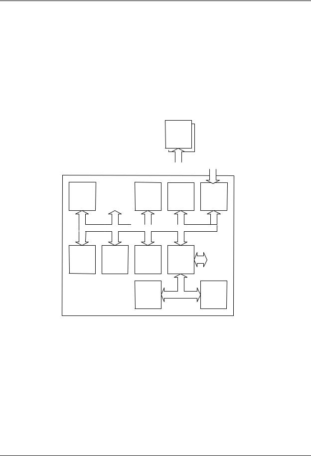
Figure 7 General bus structure of MRI Monitor
cam_p1_gnrl_bus_strctr_cm.vsd
The CPU bus is a communication channel used only for internal data transfer. It is based on the ISA bus used in IBM PC computers. Data is transferred on this 16 bit wide bus using the CPU clock frequency.
The module bus is for the parameter modules. The bus is based on the industry standard RS-485, which uses a differential serial method to transfer data. This type of bus is robust and it allows parameter modules to be inserted or removed while the power is on. The module bus uses a 500 kbps data transfer rate.
The RS-485 type of serial communication supports so-called multidrop or party line connections. This means that all parameter modules connected to the module bus use exactly the same lines for communication.
20
Document no. M1041746 -1
System description
2.3Distributed processing
The system is a multiprocessor system. All parameter modules have their own microprocessor, which performs functions such as module key control, waveform filtering, parameter related computing and pneumatic control, etc. At the same time the main CPU performs higher level tasks such as trending and alarm control. While the parameter modules and CPU are performing their tasks, the UPI (Universal Peripheral Interface) microprocessor handles all functions needed to transfer data between the parameter modules and the CPU.
This kind of parallel processing gives one major advantage to centralized processing. When new parameter modules are added to the system, the processing power is increased. As a result, the system does not slow down when new features are added.
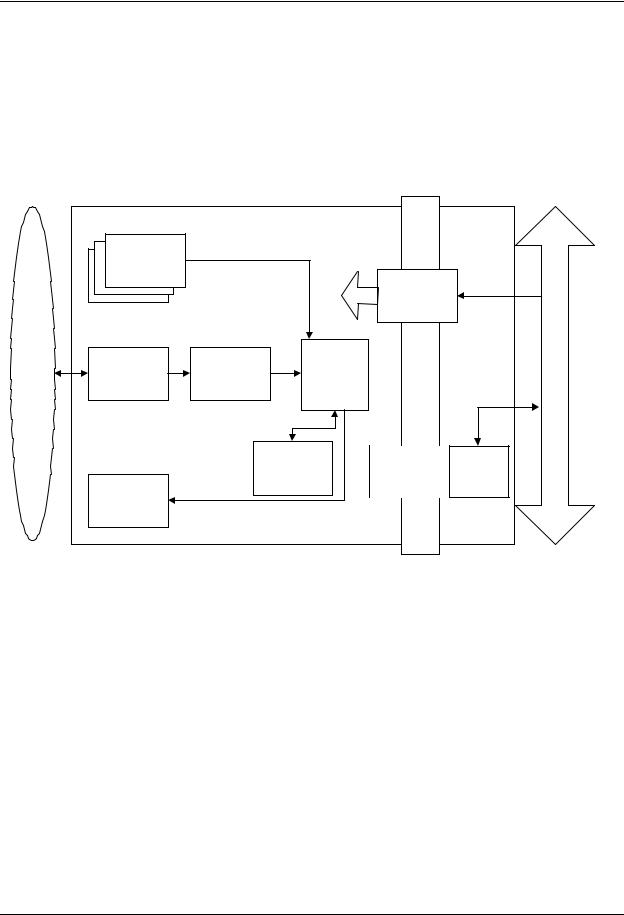
2.4Module communication
The communication master controlling data transfers between the CPU and parameter modules is called UPI processor. It sends data to each connected module 100 times a second. Modules respond to each data request immediately by sending a data package, whose length depends on the type of the module. This communication protocol ensures that each module receives and sends data every 10 ms. If a module does not respond to data requests, the UPI processor presumes that the module is disconnected.
Parameter modules may hold a static (fixed) or dynamic address, which the UPI processor uses when sending out data. Two parameter modules of the same type must not be fitted onto the same monitor since they might reply to a data request simultaneously, thus causing communication errors.
ISA-BUS
|
|
|
Voltage |
Temp |
|
||
|
Shared |
|
Meas |
|
Meas |
|
|
|
|
|
|
|
|
|
|
|
|
|
|
|
|
|
|
|
SRAM |
|
|
|
|
|
Analog & Digital outputs |
|
|
|
|
|
|
|
|
|
|
|
|
|
|
|
|
|
|
|
|
|
|
|
|
Control |
UPI |
Module Bus |
|||||
Logic |
Processor |
|
|||||
|
|
|
|
|
|
|
|
ComWheel Interface
Keypad Interface
cam_p1_prncpl_UPI_operation.vsd
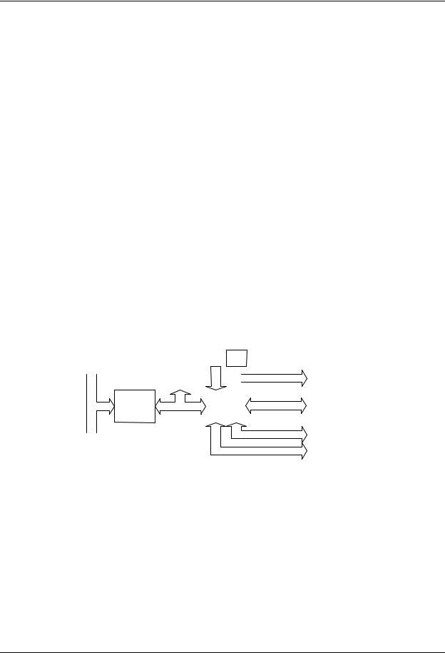
Figure 8 Principle of UPI section operation
The UPI processor collects and stores all data that is received from the parameter modules into a shared SRAM, which is mapped directly to the address space of the main CPU. The main CPU reads data from the memory while the UPI processor guarantees that the data is up to date. This operation also works in the other direction. In this the main CPU fills the shared SRAM with data and the UPI processor distributes it to the parameter modules.
21
Document no. M1041746 -1
MRI Monitor
2.5Software loading
The program memory on the CPU board is loaded with monitor software at the factory. The software is used for running all the functions that are integrated into the PC board. For service and upgrade procedures, the CPU board is fitted with a PCMCIA card drive through which new software can be loaded.
2.6Parameter modules
|
Module |
|
+5 V |
|
|
|
|
keys |
|
|
|
|
|
|
|
+12 V |
|
+13...16 V |
|
|
|
|
|
Isolation |
|
||
|
|
|
|
VMOD |
|
|
|
|
|
|
transformer |
|
|
PATIENT |
Analog |
A/D |
CPU |
Patient isolation |
|
Module Bus |
electronics |
converter |
Data |
||||
|
|
|
||||
|
|
|
|
|||
|
|
|
RAM |
Opto |
RS485 |
|
|
Peripheral |
|
EEPROM |
isolation |
drivers |
|
|
|
|
|
|
|
|
|
drivers |
|
|
|
|
|
Figure 9 General structure of parameter modules with patient isolation
general_struct_of_parm_mod.vsd
The detailed structure of a parameter module depends on the specific needs for each individual parameter. However, some common parts are used in the parameter modules. The electronics inside the module is usually divided into isolated (floating) and non-isolated sections. Typically, the non-isolated section consists of buffers to interface the parameter module to the module bus while the rest of the electronics is located in the isolated section. The isolated section includes the microcontroller together with memory components, the front-end analog electronics (amplifiers, etc.) and sensor drivers.
22
Document no. M1041746 -1
Loading...