


 Loading...
Aespire View
User’s Reference Manual
Software Revision 6.X
Datex-Ohmeda, Inc., a General Electric Company, doing business as GE Healthcare.
User Responsibility
This Product will perform in conformity with the description thereof contained in this User’s Reference manual and accompanying labels and/or inserts, when assembled, operated, maintained, and repaired in accordance with the instructions provided. This Product must be checked periodically. A defective Product should not be used. Parts that are broken, missing, plainly worn, distorted, or contaminated should be replaced immediately. Should repair or replacement become necessary, Datex-Ohmeda recommends that a telephonic or written request for service advice be made to the nearest Datex-Ohmeda Customer Service Center. This Product or any of its parts should not be repaired other than in accordance with written instructions provided by Datex-Ohmeda and by Datex-Ohmeda trained personnel. The Product must not be altered without the prior written approval of Datex-Ohmeda. The user of this Product shall have the sole responsibility for any malfunction which results from improper use, faulty maintenance, improper repair, damage, or alteration by anyone other than Datex-Ohmeda.
CAUTION U.S. Federal law restricts this device to sale by or on the order of a licensed medical practitioner. Outside the U.S.A., check local laws for any restriction that may apply.
Datex-Ohmeda products have unit serial numbers with coded logic which indicates a product group code, the year of manufacture, and a sequential unit number for identification. The serial number can be in one of two formats.
AAAX11111 |
AAAXX111111AA |
The X represents an alpha |
The XX represents a number |
character indicating the year |
indicating the year the product |
the product was manufactured; |
was manufactured; 04 = 2004, |
H = 2004, J = 2005, etc. I and |
05 = 2005, etc. |
O are not used. |
|
Aespire, 7900 Ventilator, Advanced Breathing System, Link-25, ComWheel, Disposable Multi Absorber, EZchange, Reusable Multi Absorber, PSVPro, SmartVent, Tec 6, and Tec 7 are registered trademarks of Datex-Ohmeda, Inc.
Other brand names or product names used in this manual are trademarks or registered trademarks of their respective holders.
Table of Contents
1 Introduction
Intended use . . . . . . . . . . . . . . . . . . . . . . . . . . . . . . . . . . . . 1-2 Symbols used in the manual or on the equipment . . . . . . . . 1-3 Typeface conventions used . . . . . . . . . . . . . . . . . . . . . . . . . 1-6 Abbreviations . . . . . . . . . . . . . . . . . . . . . . . . . . . . . . . . . . . . 1-6
2 System Controls and Menus
Anesthesia system controls . . . . . . . . . . . . . . . . . . . . . . . . . 2-2 Advanced breathing system (ABS) components . . . . . . . . . 2-5 Optional ABS components . . . . . . . . . . . . . . . . . . . . . . . 2-7 Vaporizer controls . . . . . . . . . . . . . . . . . . . . . . . . . . . . . . . . 2-8 ACGO . . . . . . . . . . . . . . . . . . . . . . . . . . . . . . . . . . . . . . . . 2-10 Scavenging the ACGO sample flow . . . . . . . . . . . . . . . 2-11 Scavenging from an auxiliary manual breathing circuit 2-11 Scavenging a gas monitor sample flow . . . . . . . . . . . . 2-11 Ventilator controls . . . . . . . . . . . . . . . . . . . . . . . . . . . . . . . 2-12 Ventilator screen . . . . . . . . . . . . . . . . . . . . . . . . . . . . . . . . 2-13 Using menus . . . . . . . . . . . . . . . . . . . . . . . . . . . . . . . . . . . 2-14
3 Operation
Turning on the system . . . . . . . . . . . . . . . . . . . . . . . . . . . . . 3-2
Start mechanical ventilation . . . . . . . . . . . . . . . . . . . . . . . . . 3-2
Start manual ventilation . . . . . . . . . . . . . . . . . . . . . . . . . . . . 3-2
Ventilator setup . . . . . . . . . . . . . . . . . . . . . . . . . . . . . . . . . . 3-3
Using quick keys . . . . . . . . . . . . . . . . . . . . . . . . . . . . . . 3-3
Changing ventilator modes and settings . . . . . . . . . . . . 3-4
Alarm Setup . . . . . . . . . . . . . . . . . . . . . . . . . . . . . . . . . . . . . 3-5
Setting volume alarms . . . . . . . . . . . . . . . . . . . . . . . . . . 3-5
Alarm limit setup . . . . . . . . . . . . . . . . . . . . . . . . . . . . . . 3-5
Setup/Calibration . . . . . . . . . . . . . . . . . . . . . . . . . . . . . . . . . 3-6
M1132382 |
i |
Aespire View
Screen and audio setup . . . . . . . . . . . . . . . . . . . . . . . . . . . . 3-7 Cardiac Bypass . . . . . . . . . . . . . . . . . . . . . . . . . . . . . . . . . . 3-8 Measure circuit compliance . . . . . . . . . . . . . . . . . . . . . . . . . 3-9 Pressure waveform . . . . . . . . . . . . . . . . . . . . . . . . . . . . . . . 3-9 EZchange canister (optional) . . . . . . . . . . . . . . . . . . . . . . . 3-10 Condenser (optional) . . . . . . . . . . . . . . . . . . . . . . . . . . . . . 3-11 Passive AGSS (optional) . . . . . . . . . . . . . . . . . . . . . . . . . . 3-12
Connecting passive AGSS . . . . . . . . . . . . . . . . . . . . . . 3-12 Active AGSS (optional) . . . . . . . . . . . . . . . . . . . . . . . . . . . 3-13 Connecting active AGSS with a flow indicator . . . . . . . 3-14 Connecting active adjustable AGSS . . . . . . . . . . . . . . 3-15 Total flow sensing (optional) . . . . . . . . . . . . . . . . . . . . . . . 3-15
4 Preoperative Checkout
Every day before your first patient . . . . . . . . . . . . . . . . . . . . 4-2 Before every patient . . . . . . . . . . . . . . . . . . . . . . . . . . . . . . . 4-3
5 Preoperative Tests
Inspect the system . . . . . . . . . . . . . . . . . . . . . . . . . . . . . . . . 5-2
Power failure alarm test . . . . . . . . . . . . . . . . . . . . . . . . . . . . 5-3
Pipeline test . . . . . . . . . . . . . . . . . . . . . . . . . . . . . . . . . . . . . 5-3
Total flow sensing test (if equipped) . . . . . . . . . . . . . . . . . . 5-3
Cylinder test . . . . . . . . . . . . . . . . . . . . . . . . . . . . . . . . . . . . . 5-4
Flow control test . . . . . . . . . . . . . . . . . . . . . . . . . . . . . . . . . . 5-5
Vaporizer installation . . . . . . . . . . . . . . . . . . . . . . . . . . . . . . 5-7
Vaporizer back pressure test . . . . . . . . . . . . . . . . . . . . . . . . 5-8
Low-pressure leak test . . . . . . . . . . . . . . . . . . . . . . . . . . . . . 5-9
Negative low-pressure leak test . . . . . . . . . . . . . . . . . . . 5-9
Positive low-pressure leak test . . . . . . . . . . . . . . . . . . 5-10
Alarm tests . . . . . . . . . . . . . . . . . . . . . . . . . . . . . . . . . . . . . 5-11
Breathing system tests . . . . . . . . . . . . . . . . . . . . . . . . . . . 5-13
Bellows test . . . . . . . . . . . . . . . . . . . . . . . . . . . . . . . . . 5-13
Breathing circuit test . . . . . . . . . . . . . . . . . . . . . . . . . . 5-14
APL valve test . . . . . . . . . . . . . . . . . . . . . . . . . . . . . . . 5-14
Monitor and ventilator tests . . . . . . . . . . . . . . . . . . . . . . . . 5-15
ii |
M1132382 |
Table of Contents
6 Alarms and Troubleshooting
Alarms . . . . . . . . . . . . . . . . . . . . . . . . . . . . . . . . . . . . . . . . . 6-2 Audio . . . . . . . . . . . . . . . . . . . . . . . . . . . . . . . . . . . . . . . 6-2 Display . . . . . . . . . . . . . . . . . . . . . . . . . . . . . . . . . . . . . . 6-2 Latching alarms . . . . . . . . . . . . . . . . . . . . . . . . . . . . . . . 6-3 List of alarms . . . . . . . . . . . . . . . . . . . . . . . . . . . . . . . . . . . . 6-4 Minimum system shutdown and monitoring alarms . . . . 6-9 Alarm ranges . . . . . . . . . . . . . . . . . . . . . . . . . . . . . . . . . . . 6-10 Alarm tests . . . . . . . . . . . . . . . . . . . . . . . . . . . . . . . . . . . . . 6-10 Breathing system problems . . . . . . . . . . . . . . . . . . . . . . . . 6-12 Electrical problems . . . . . . . . . . . . . . . . . . . . . . . . . . . . . . . 6-13 Pneumatic problems . . . . . . . . . . . . . . . . . . . . . . . . . . . . . 6-14
7 User Maintenance
Repair policy . . . . . . . . . . . . . . . . . . . . . . . . . . . . . . . . . . . . 7-2 Maintenance summary and schedule . . . . . . . . . . . . . . . . . 7-2 User maintenance . . . . . . . . . . . . . . . . . . . . . . . . . . . . . 7-3 Datex-Ohmeda approved service . . . . . . . . . . . . . . . . . 7-3 Breathing system maintenance . . . . . . . . . . . . . . . . . . . . . . 7-3 O2 cell replacement . . . . . . . . . . . . . . . . . . . . . . . . . . . . . . . 7-4 O2 cell calibration . . . . . . . . . . . . . . . . . . . . . . . . . . . . . . . . 7-5 21% O2 cell calibration . . . . . . . . . . . . . . . . . . . . . . . . . 7-5 100% O2 cell calibration . . . . . . . . . . . . . . . . . . . . . . . . 7-6 Zeroing flow sensor . . . . . . . . . . . . . . . . . . . . . . . . . . . . . . . 7-6 Prevent water buildup . . . . . . . . . . . . . . . . . . . . . . . . . . . . . 7-7
M1132382 |
iii |
Aespire View
8 Setup and Connections
Canister setup . . . . . . . . . . . . . . . . . . . . . . . . . . . . . . . . . . . 8-4 When to change the absorbent . . . . . . . . . . . . . . . . . . . 8-6 Removing a canister . . . . . . . . . . . . . . . . . . . . . . . . . . . 8-6 Removing an EZchange canister . . . . . . . . . . . . . . . . . . 8-7 Reusable Multi Absorber canister filling . . . . . . . . . . . . . 8-7
Electrical connections . . . . . . . . . . . . . . . . . . . . . . . . . . . . . 8-9 Outlets . . . . . . . . . . . . . . . . . . . . . . . . . . . . . . . . . . . . . . 8-9 Mains inlet . . . . . . . . . . . . . . . . . . . . . . . . . . . . . . . . . . 8-10 Serial port . . . . . . . . . . . . . . . . . . . . . . . . . . . . . . . . . . . 8-10 Pneumatic connections . . . . . . . . . . . . . . . . . . . . . . . . . . . 8-10 Pipeline Inlets . . . . . . . . . . . . . . . . . . . . . . . . . . . . . . . . 8-10 Scavenging . . . . . . . . . . . . . . . . . . . . . . . . . . . . . . . . . 8-11 Sample gas return port . . . . . . . . . . . . . . . . . . . . . . . . 8-11 Suction regulator (optional) . . . . . . . . . . . . . . . . . . . . . 8-12 Auxiliary O2 flowmeter (optional) . . . . . . . . . . . . . . . . . 8-12 How to install gas cylinders . . . . . . . . . . . . . . . . . . . . . . . . 8-13 Pin indexed cylinder yokes . . . . . . . . . . . . . . . . . . . . . 8-13 DIN cylinder connections . . . . . . . . . . . . . . . . . . . . . . . 8-13 High-pressure leak test . . . . . . . . . . . . . . . . . . . . . . . . 8-14 How to attach equipment to the top of the machine . . . . . . 8-14
9 Parts
Flow sensor module . . . . . . . . . . . . . . . . . . . . . . . . . . . . . . . 9-2
Exhalation valve assembly . . . . . . . . . . . . . . . . . . . . . . . . . . 9-2
Breathing circuit module . . . . . . . . . . . . . . . . . . . . . . . . . . . 9-3
Bellows assembly . . . . . . . . . . . . . . . . . . . . . . . . . . . . . . . . 9-4
Absorber canister . . . . . . . . . . . . . . . . . . . . . . . . . . . . . . . . . 9-5
AGSS . . . . . . . . . . . . . . . . . . . . . . . . . . . . . . . . . . . . . . . . . . 9-6
EZchange canister system . . . . . . . . . . . . . . . . . . . . . . . . . . 9-7
Condenser . . . . . . . . . . . . . . . . . . . . . . . . . . . . . . . . . . . . . . 9-8
Test tools and system parts . . . . . . . . . . . . . . . . . . . . . . . . . 9-9
iv |
M1132382 |
Table of Contents
10 Specifications and Theory of Operation
System pneumatic circuits . . . . . . . . . . . . . . . . . . . . . . . . . 10-2
Gas supplies . . . . . . . . . . . . . . . . . . . . . . . . . . . . . . . . 10-4
O2 flow . . . . . . . . . . . . . . . . . . . . . . . . . . . . . . . . . . . . . 10-4
N2O flow . . . . . . . . . . . . . . . . . . . . . . . . . . . . . . . . . . . 10-4
Air flow . . . . . . . . . . . . . . . . . . . . . . . . . . . . . . . . . . . . . 10-4
Mixed gas . . . . . . . . . . . . . . . . . . . . . . . . . . . . . . . . . . . 10-5
EZchange canister . . . . . . . . . . . . . . . . . . . . . . . . . . . . 10-5
Condenser . . . . . . . . . . . . . . . . . . . . . . . . . . . . . . . . . . 10-5
Pneumatic specifications . . . . . . . . . . . . . . . . . . . . . . . . . . 10-5
Gas supplies . . . . . . . . . . . . . . . . . . . . . . . . . . . . . . . . 10-5
ACGO Port relief . . . . . . . . . . . . . . . . . . . . . . . . . . . . . 10-5
Electrical block diagram . . . . . . . . . . . . . . . . . . . . . . . . . . . 10-6
Electrical power . . . . . . . . . . . . . . . . . . . . . . . . . . . . . . . . . 10-7
Power cord . . . . . . . . . . . . . . . . . . . . . . . . . . . . . . . . . . 10-8
Battery information . . . . . . . . . . . . . . . . . . . . . . . . . . . . 10-8
Flow specifications . . . . . . . . . . . . . . . . . . . . . . . . . . . . . . . 10-9
Pneumatic flow . . . . . . . . . . . . . . . . . . . . . . . . . . . . . . . 10-9
Breathing system specifications . . . . . . . . . . . . . . . . . . . . 10-10
Gas scavenging . . . . . . . . . . . . . . . . . . . . . . . . . . . . . 10-11
Physical specifications . . . . . . . . . . . . . . . . . . . . . . . . . . . 10-12
Environmental requirements . . . . . . . . . . . . . . . . . . . . . . 10-12
Suction regulators (optional) . . . . . . . . . . . . . . . . . . . . . . 10-13
Auxiliary O2 flowmeter (optional) . . . . . . . . . . . . . . . . . . . 10-13
Ventilator theory . . . . . . . . . . . . . . . . . . . . . . . . . . . . . . . . 10-14
O2 monitoring theory of operation . . . . . . . . . . . . . . . 10-15
Modes . . . . . . . . . . . . . . . . . . . . . . . . . . . . . . . . . . . . 10-15
Ventilator operating specifications . . . . . . . . . . . . . . . . . . 10-23
Pneumatics . . . . . . . . . . . . . . . . . . . . . . . . . . . . . . . . 10-23
Fresh gas compensation . . . . . . . . . . . . . . . . . . . . . . 10-23
Pressure . . . . . . . . . . . . . . . . . . . . . . . . . . . . . . . . . . . 10-23
Volume . . . . . . . . . . . . . . . . . . . . . . . . . . . . . . . . . . . . 10-23
Oxygen . . . . . . . . . . . . . . . . . . . . . . . . . . . . . . . . . . . . 10-23
Ventilator accuracy data . . . . . . . . . . . . . . . . . . . . . . . . . 10-24
M1132382 |
v |
Aespire View
Electromagnetic compatibility (EMC) . . . . . . . . . . . . . . . . 10-26
Guidance and manufacturer’s declaration - electromagnetic emissions . . . . . . . . . . . . . . . . . . . . . 10-26
Guidance and manufacturer’s declaration - electromagnetic immunity . . . . . . . . . . . . . . . . . . . . . 10-27
Recommended separation distances . . . . . . . . . . . . . 10-29 Electrical safety . . . . . . . . . . . . . . . . . . . . . . . . . . . . . . . . 10-30 IEC 60601-1 Classification . . . . . . . . . . . . . . . . . . . . . . . . 10-31 Standards . . . . . . . . . . . . . . . . . . . . . . . . . . . . . . . . . . . . 10-31 System components . . . . . . . . . . . . . . . . . . . . . . . . . . . . 10-32
Integral . . . . . . . . . . . . . . . . . . . . . . . . . . . . . . . . . . . . 10-32 Not integral . . . . . . . . . . . . . . . . . . . . . . . . . . . . . . . . . 10-32
Index
Warranty
vi |
M1132382 |
1 Introduction
In this section Intended use . . . . . . . . . . . . . . . . . . . . . . . . . . . . . . . . . . . . . 1-2 Symbols used in the manual or on the equipment . . . . . . . . 1-3 Typeface conventions used . . . . . . . . . . . . . . . . . . . . . . . . . 1-6 Abbreviations . . . . . . . . . . . . . . . . . . . . . . . . . . . . . . . . . . . . 1-6
M1132382 |
1-1 |
Aespire View
Intended use
The Aespire anesthesia system is a compact, integrated, and intuitive anesthesia delivery system. The 7900 Ventilator provides mechanical ventilation for patients during surgery as well as monitoring and displaying various patient parameters.
The 7900 Ventilator uses a microprocessor-controlled ventilator with internal monitors, electronic PEEP, Volume Mode, and other optional features. A serial interface permits communication to external monitoring.
This anesthesia system is not suitable for use in an MRI environment.
This system must only be operated by medical personnel authorized and trained to use this product. It must be operated according to the instructions in this User’s Reference manual.
Note Configurations available for this product depend on local market and standards requirements. Illustrations in this manual may not represent all configurations of the product. This manual does not cover the operation of every accessory. Refer to the accessory documentation for further information.
1-2 |
M1132382 |
1 Introduction
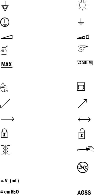
Symbols used in the manual or on the equipment
Symbols replace words on the equipment, on the display, or in manuals.
Warnings and Cautions tell about the dangerous conditions that can occur if the instructions in the manual are not followed.
Warnings tell about a condition that can cause injury to the operator or the patient.
|
|
|
|
|
|
|
|
|
|
|
Cautions tell about a condition that can cause damage to the |
|||||||||||
|
|
|
|
|
|
|
|
|
|
|
equipment. Read and follow all warnings and cautions. |
|||||||||||
|
|
|
|
|
|
|
|
|
|
|
On (power) |
O2+ |
Off (power) |
|||||||||
|
|
|
|
|
|
|
|
|
|
|
||||||||||||
|
|
|
|
|
|
|
|
|
|
|
Standby |
O2 flush button |
||||||||||
|
|
|
|
|
|
|
|
|
|
|
||||||||||||
|
|
|
|
|
|
|
|
|
|
|
|
|
|
|
|
|
|
|
|
|
||
|
|
|
|
|
|
|
|
|
|
|
Type BF equipment |
|
|
|
|
|
|
|
|
|
|
Type B equipment |
|
|
|
|
|
|
|
|
|
|
|
Dangerous voltage |
|
|
|
|
|
|
|
|
|
|
Frame or chassis ground |
|
|
|
|
|
|
|
|
|
|
|||||||||||||
|
|
|
|
|
|
|
|
|
|
|
Direct current |
|
|
|
|
|
|
|
|
|
|
Alternating current |
|
|
|
|
|
|
|
|
|
|
|
|
|
|
|
|
|
|
|
|
|
||
|
|
|
|
|
|
|
|
|
|
|
Caution |
|
|
|
|
|
|
|
|
|
|
Attention, refer to product instructions |
|
|
|
|
|
|
|
|
|
|
|
|
|
|
|
|
|
|
|
|
|
||
|
|
|
|
|
|
|
|
|
|
|
Refer to product instructions |
|
|
|
|
|
|
|
|
|
|
Exhaust |
|
|
|
|
|
|
|
|
|
|
|
|
|
|
|
|
|
|
|
|
|
||
|
|
|
|
|
|
|
|
|
|
|
Electrical input |
|
|
|
|
|
|
|
|
|
|
Electrical output |
|
|
|
|
|
|
|
|
|
|
|
|
|
|
|
|
|
|
|
|
|
||
|
|
|
|
|
|
|
|
|
|
|
Electrical input/output |
|
|
|
|
|
|
|
|
|
|
Sample gas inlet to scavenging |
|
|
|
|
|
|
|
|
|
|
|
|
|
|
|
|
|
|
|
|
|
||
|
|
|
|
|
|
|
|
|
|
|
Pneumatic inlet |
|
|
|
|
|
|
|
|
|
|
Pneumatic outlet |
|
|
|
|
|
|
|
|
|
|
|
|
|
|
|
|
|
|
|
|
|
||
|
|
|
|
|
|
|
|
|
|
|
|
|
|
|
|
|
|
|
|
|
|
|
SN
Serial number |
REF |
|
Stock number
M1132382 |
1-3 |
Aespire View
Equipotential
Protective earth ground
Variability
Suction bottle outlet
Max
+Plus, positive polarity
Bag position/manual ventilation
Inspiratory flow
Movement in one direction
Lock
Isolation transformer
134°C Autoclavable
Bellows volumes are approximate
APL settings are approximate
Lamp, lighting, illumination
Earth ground
Variability in steps
Vacuum inlet
Vacuum
-Minus, negative polarity
Mechanical ventilation
Expiratory flow
Movement in two directions
Unlock
Low pressure leak test
Not autoclavable
O2% |
O2 cell connection |
|
|
|
Anesthetic Gas Scavenging System |
1-4 |
M1132382 |
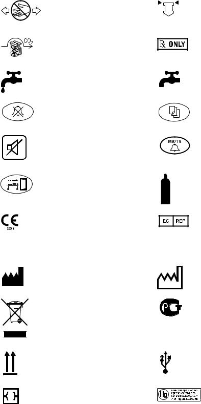
Pinch hazard
EZchange Canister (CO2 bypass)
Open drain (remove liquid)
Alarm silence touch key
Silence alarm touch key (Tec 6)
End case touch key
Systems with this mark agree with the European Council Directive (93/42/EEC) for Medical Devices when they are used as specified in their User’s Reference manuals. The xxxx is the certification number of the Notified Body used by GE Healthcare’s Quality Systems.
Manufacturer
Indicates that the waste of electrical and electronic equipment must not be disposed as unsorted municipal waste and must be collected separately. Please contact an authorized representative of Datex-Ohmeda for information concerning the decommissioning of equipment.
This way up
Ethernet connection
1 Introduction
Read to top of float
Caution: federal law prohibits dispensing without prescription
Close drain
Menu touch key
Volume alarms On/Off touch key
Cylinder
Authorized representative in the European Community
Date of manufacture
GOST R Russian certification
USB port
This product consists of devices that may contain mercury, which must be recycled or disposed of in accordance with local, state, or country laws. (Within this system, the backlight lamps in the monitor display contain mercury.
M1132382 |
1-5 |
Aespire View
Typeface conventions used
Menu items are written in bold italic typeface; for example, Main Menu.
Messages that are displayed on the screen are enclosed in single quotes: for example, ‘Total pressure exceeds Pmax.’
When referring to different sections and other documents, the names are written in italic typeface and enclosed in double quotes; for example, “System Controls and Menus.”
Abbreviations
Abbreviation |
Definition |
A |
|
ABS |
Advanced breathing system |
ACGO |
Auxiliary common gas outlet |
AGSS |
Anesthetic gas scavenging system |
APL |
Adjustable pressure-limiting valve |
C |
|
CO2 |
Carbon dioxide |
D |
|
DAC |
Digital to analog converter |
E |
|
EMC |
Electromagnetic compatibility |
ESD |
Electrostatic discharge |
I:E |
Inspiratory-expiratory ratio |
F |
|
FiO2 |
Fraction of inspired oxygen |
M |
|
MIN |
Minimum |
MV |
Minute volume |
MVexp |
Expired minute volume |
O |
|
O2 |
Oxygen |
1-6 |
M1132382 |
|
1 Introduction |
P |
|
Paw |
Patient airway pressure |
PCV |
Pressure controlled ventilation |
PCV-VG |
Pressure controlled ventilation - volume guaranteed |
PEEP |
Positive end expiratory pressure |
Pmax |
Maximum pressure |
Pmean |
Average pressure calculated over the patient breath |
Pinsp |
Target airway pressure |
Ppause |
Positive airway pressure measured at the end of |
|
Tpause |
Ppeak |
Maximum airway pressure measured during patient |
|
breath |
Psupport |
Pressure support |
PSVPro |
Pressure supported ventilation with apnea backup |
R |
|
RR |
Respiratory rate |
S |
|
SIMV-PC |
Synchronized intermittent mandatory ventilation - |
|
pressure controlled |
SIMV/PSV |
Synchronized intermittent mandatory ventilation / |
|
pressure supported ventilation |
T |
|
TFS |
Total flow sensing |
Tpause |
Pause time |
Tinsp |
Inspired tidal volume |
TV |
Tidal volume |
TVexp |
Expired tidal volume |
V |
|
VCV |
Volume controlled ventilation |
M1132382 |
1-7 |
Aespire View
1-8 |
M1132382 |
2 System Controls and Menus
WARNING Explosion Hazard. Do not use this system with flammable anesthetic agents.
wDo not use antistatic or electrically-conductive breathing tubes or masks. They can cause burns if used near high frequency surgical equipment.
In this section Anesthesia system controls . . . . . . . . . . . . . . . . . . . . . . . . . 2-2 Advanced breathing system (ABS) components . . . . . . . . . 2-5 Vaporizer controls. . . . . . . . . . . . . . . . . . . . . . . . . . . . . . . . . 2-8 ACGO . . . . . . . . . . . . . . . . . . . . . . . . . . . . . . . . . . . . . . . . . 2-10 Ventilator controls . . . . . . . . . . . . . . . . . . . . . . . . . . . . . . . . 2-12 Ventilator screen. . . . . . . . . . . . . . . . . . . . . . . . . . . . . . . . . 2-13 Using menus. . . . . . . . . . . . . . . . . . . . . . . . . . . . . . . . . . . . 2-14
M1132382 |
2-1 |
Aespire View
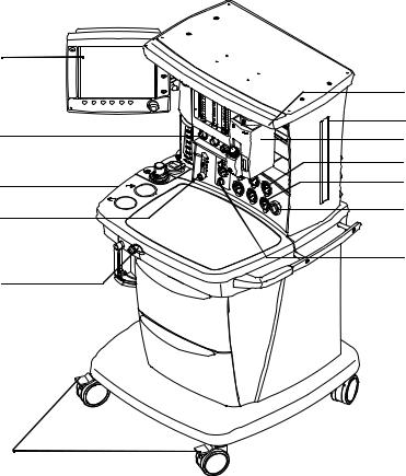
Anesthesia system controls
13 |
|
|
1 |
12 |
2 |
3 |
|
|
4 |
11 |
5 |
10 |
6 |
|
|
|
7 |
9 |
|
|
8 |
|
|
1. |
Light switch |
8. |
Brake |
2. |
Dovetail rails |
9. |
O2 flush button |
3. |
Vaporizer |
10. Auxiliary O2 flow control (optional) |
|
4. |
Pipeline pressure gauge(s) (upper row) |
11. Breathing system |
|
5. |
Cylinder pressure gauge(s) (lower row) |
12. Flow controls |
|
6. |
System switch |
13. Ventilator display |
|
7. |
Integrated suction (optional) |
|
|
Figure 2-1 • Front view
AC.20.002
2-2 |
M1132382 |
2 System Controls and Menus
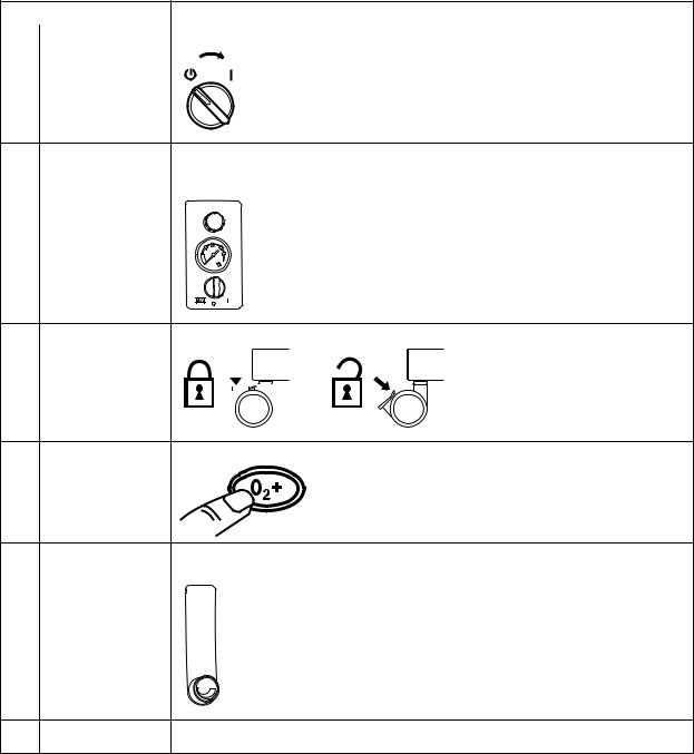
Item, Figure 2-1 |
Description |
|
6 |
System switch |
Set the switch to the On (|) position to permit gas flow and to turn on the system. |
7 |
Integrated suction |
Turn the switch to MAX for full vacuum. Turn the switch to Off (0) for no vacuum. Turn |
|
(optional) |
the switch to On (|) for adjustable vacuum. When in adjustable vacuum, turn the knob |
|
|
clockwise to increase the vacuum and counterclockwise to decrease the vacuum. |
8 |
Brake |
Push down to lock. Lift to release. |
||||||||
|
|
|
|
|
|
|
|
|
|
|
|
|
|
|
|
|
|
|
|
|
|
|
|
|
|
|
|
|
|
|
|
|
|
|
|
|
|
|
|
|
|
|
|
|
|
|
|
|
|
|
|
|
|
|
9 |
O2 flush button |
Push the O2 flush button to supply high flows of O2 to the breathing system. |
10 |
Auxiliary O2 flow |
Turn the knob counterclockwise to increase the flow. Turn the knob clockwise to |
||||
|
control (optional) |
decrease the flow. |
||||
|
|
|
|
|
|
|
|
|
|
|
|
|
|
|
|
|
|
|
|
|
|
|
|
|
|
|
|
|
|
|
|
|
|
|
|
|
|
|
|
|
|
|
|
|
|
|
|
|
|
|
|
|
|
|
|
|
|
|
|
|
|
|
|
|
|
|
|
|
|
|
|
|
|
|
|
|
|
|
|
|
|
|
|
|
|
|
|
|
|
|
|
|
|
|
|
|
|
|
|
|
|
|
|
|
|
|
|
|
|
|
|
|
|
|
|
|
|
|
|
|
|
|
|
|
|
|
|
|
|
|
|
|
12 |
Flow controls |
Turn the knob counterclockwise to increase the flow. Turn the knob clockwise to |
|
|
decrease the flow. The System switch must be On for gas to flow. |
M1132382 |
2-3 |
Aespire View


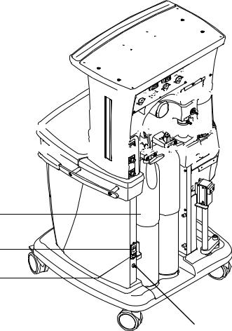
 1
1 


 2
2


 3 8
3 8 


7 |
6 |
5 |
 4
4
1. |
Outlet circuit breaker |
5. |
Mains inlet |
2. |
Electrical outlet |
6. |
System circuit breaker |
3. |
Suction items (optional) |
7. |
Cylinder |
4. |
Equipotential stud |
8. |
Pipeline connections |
Figure 2-2 • Rear view
AC.20.012
2-4 |
M1132382 |
2 System Controls and Menus
Advanced breathing system (ABS) components
17
16
15
14
13
12
11
10
9
8


 1
1 


 2
2


 3
3


 4
4
5


 6
6 
 7
7
AC.20.013
1. |
Expiratory check valve |
10. Breathing system release |
2. |
Inspiratory check valve |
11. Manual bag port |
3. |
Auxiliary common gas outlet (ACGO) switch |
12. Adjustable pressure-limiting (APL) valve |
4. |
ACGO |
13. Bag/Vent switch |
5. |
Inspiratory flow sensor |
14. Bellows assembly |
6. |
Expiratory flow sensor |
15. Sample gas return port |
7. |
Absorber canister |
16. Scavenger flow indicator (optional) |
8. |
Absorber canister release |
17. Airway pressure gauge |
9. |
Leak test plug |
|
Figure 2-3 • Advanced breathing system
M1132382 |
2-5 |
Aespire View
Item, Figure 2-3 |
Description |
|
3 |
Auxiliary common gas outlet |
Sends fresh gas to the ACGO when the switch is activated. The ACGO |
|
(ACGO) switch |
provides fresh gas to an external manual breathing circuit. |
5,6 |
Inspiratory flow sensor and |
Flow sensors provide volume measurements for some monitoring |
|
Expiratory flow sensor |
functions and tidal volume delivery. |
8 |
Absorber canister release |
Push to remove the canister. This causes the breathing system to vent to |
|
|
the room (unless the EZchange canister option is installed). Be sure to hold |
|
|
the canister by the handle before releasing the canister. |
12 |
Adjustable pressure-limiting |
Adjusts breathing system pressure limit during manual ventilation. The |
|||
|
(APL) valve |
scale shows approximate pressures. Above 30 cmH2O, the knob will click |
|||
|
|
as it turns. |
|
||
|
|
|
|
||
|
|
|
|
|
|
|
|
20 |
|
||
|
|
30 |
|
|
|
|
|
|
|
|
IN |
|
|
70 |
M |
||
|
|
|
|||
|
|
|
|
|
|
13 |
Bag/Vent switch |
Selects between manual ventilation (bag) or mechanical ventilation |
|||
|
|
(ventilator). |
|
||
2-6 |
M1132382 |

2 System Controls and Menus
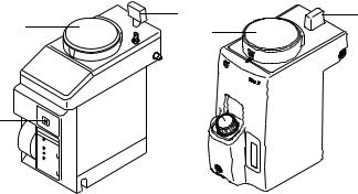
Optional ABS
components
 1
1
5
4 


1.Bag support arm
2.EZchange canister system (CO2 bypass)
3.EZchange canister release
4.Condenser drain button
5.Condenser
Figure 2-4 • Breathing system options
 2
2
 3
3
AB.82.043
AB.74.120
Item, Figure 2-4 |
Description |
||||
1 |
Bag support arm |
Squeeze the button to raise or lower the arm. |
|||
|
|
|
|
|
|
3 |
EZchange canister |
Push to drop the canister to EZchange position. This seals the breathing circuit, |
|
release |
permitting continued ventilation and rebreathing of exhaled gases. Be sure to |
|
|
hold the canister by the handle before releasing the canister. |
4 |
Condenser drain button |
Push to drain water out of the condenser. |
M1132382 |
2-7 |
Aespire View
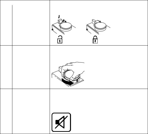
Vaporizer controls
Refer to the vaporizer User’s Reference manual for more detailed information on the vaporizer.
3
4 |
4 |
|
6
5 

1 |
2 |
1.Tec 6 series
2.Tec 7
3.Lock lever
4.Concentration control and release
5.Indicators (Tec 6 series)
6.Silence alarm touch key (Tec 6 series)
Figure 2-5 • Vaporizer controls
3
AA43051 AB.80.009
2-8 |
M1132382 |
2 System Controls and Menus
Item, Figure 2-5 |
Description |
|
3 |
Lock Lever |
Turn the lever fully clockwise to lock the vaporizer in position. |
4 |
Concentration control and |
Push the release and turn the concentration control to set the agent |
|
release |
concentration. The Tec 6 series concentration control does not turn as long |
|
|
as the warm-up indicator is on. |
5 |
Indicators (Tec 6 series) |
All indictors come on briefly at the start. The warm-up indicator goes off |
||
|
|
after approximately 10 minutes and the operational indicator comes on. |
||
|
|
Other indicators come on to advise the user of required action. |
||
6 |
Silence alarm touch key |
Push to silence alarms. Hold for 4 seconds to sound the speaker and light |
||
|
(Tec 6 series) |
all indicators (alarm test). |
||
|
|
|
|
|
|
|
|
|
|
M1132382 |
2-9 |
Aespire View
ACGO
Fresh gas flow with anesthetic agent is directed through the Auxiliary Common Gas Outlet (ACGO) on the front of the system when the ACGO switch is in the ACGO position. Mechanical ventilation is not available when operating an auxiliary manual breathing circuit with fresh gas from the ACGO. The Bag/Vent switch, APL valve, and bag arm are not part of the external circuit. Volume and pressure monitoring are not available.
O2 monitoring of fresh gas is available automatically when the ACGO is selected. A sample of the fresh gas is diverted to the O2 cell in the breathing system. The sample flow to the O2 cell is dependent on the pressure in the external circuit. The sample flow reduces the fresh gas flow rate to the auxiliary breathing circuit equal to the amount delivered to the O2 cell.
Fresh gas oxygen concentration is displayed on the screen. Set the alarm limits appropriately. Note that fresh gas oxygen concentration may not reflect FiO2 during spontaneous breathing or in rebreathing circuits.
Important Use an external O2 monitor if using a rebreathing circuit on ACGO.
Do not use an external ventilator on the ACGO. Do not use the ACGO to drive external ventilators or for jet ventilation.
See “Scavenging” in the “Setup and Connections” section for more information on connections.
WARNING The maximum pressure at the ACGO can be up to 55 kPa
(8 psi). Use a breathing circuit with pressure relief.
2-10 |
M1132382 |
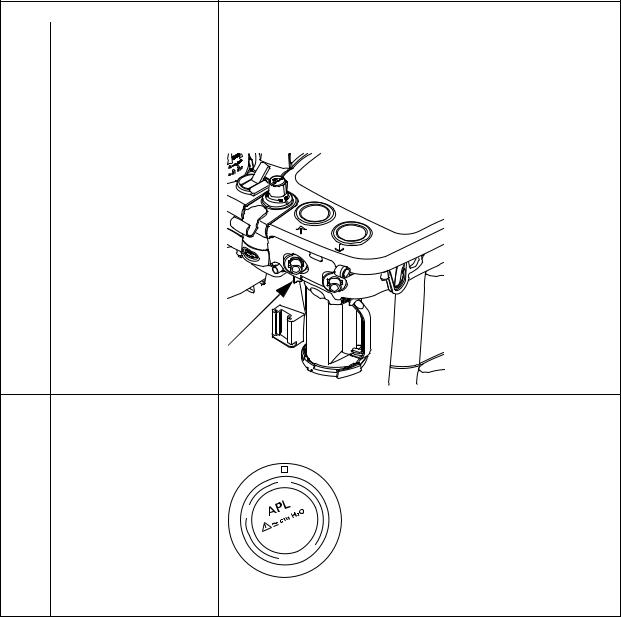
Scavenging the ACGO sample flow
2 System Controls and Menus
A sample of the fresh gas is diverted to the O2 cell in the breathing system to show the O2 numerics on the monitor display. This sample flow should be scavenged when an auxiliary manual breathing circuit is used with N2O or volatile anesthetics.
If scavenging is not connected, the sample flow is emptied into the room.
To connect the scavenging:
1.Attach a circle breathing circuit to the inspiratory and expiratory ports.
2.Occlude the circle circuit by connecting the Y-piece to the plug located to the rear of the expiratory port.
3.Check for clinically correct settings.
4.Check the position of the Bag/Vent switch:
•If the Bag/Vent switch is set to mechanical ventilation mode, the bellows fills slowly with the sample flow. When the bellows is full, the sample flow goes to the AGSS (Mechanical ventilation does not start when ACGO switch is set to ACGO).
•If the Bag/Vent switch is set to bag mode, set the APL valve to MIN and attach a bag. The bag fills slowly with the sample flow. When the bag is full, the sample flow goes to the AGSS.
Scavenging from an auxiliary manual breathing circuit
Important
Scavenging a gas monitor sample flow
Scavenge the exhaust if an auxiliary manual breathing circuit is used with N2O or volatile anesthetics.
An auxiliary inlet is available for active and passive AGSS units. It provides a female connection with 30 mm male - 30 mm male connector (or a 30 mm male - 19 mm male connector) into the auxiliary port under the breathing system.
Do not use these connectors as an outlet for exhaust flow.
The auxiliary inlet is a convenience inlet to the air brake of active AGSS units. There is a reservoir to capture exhaust flows higher than the extract flow.
A separate exhaust hose is needed from the auxiliary manual breathing circuit to the disposal point for all AGSS units.
Sample gas from a gas monitor can be scavenged using the sample gas return port or the AGSS. To scavenge from a gas monitor using the sample gas return port, connect the tubing from the monitor to the sample gas return port. To scavenge from a gas monitor using the AGSS, connect tubing from the monitor to the male luer inlet on the bottom of the AGSS underneath the breathing system.
M1132382 |
2-11 |
Aespire View
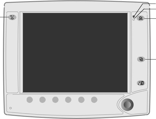
Ventilator controls
The ventilator controls include touch keys, menu screens, and a control knob (ComWheel). The System switch provides power functions to the ventilator display. The Bag/Vent switch starts and stops mechanical ventilation.
14
|
13 |
|
|
|
|
|
|
|
|
|
|
|
|
|
|
|
|
|
|
|
|
|
|
|
|
|
|
|
|
|
|
|
|
|
|
|
|
|
|
|
|
|
|
|
|
|
|
|
|
|
|
|
|
|
|
|
|
|
|
|
|
|
|
|
|
|
|
|
|
|
|
|
|
|
|
|
|
|
|
|
|
|
|
|
|
|
|
|
|
|
|
|
|
|
|
|
|
|
|
|
|
|
|
|
|
|
|
|
|
|
|
|
|
|
|
|
|
|
|
|
|
|
|
|
|
|
|
|
|
|
|
|
|
|
|
|
|
|
|
|
|
|
|
|
|
|
|
|
|
|
|
|
|
|
|
|
|
|
|
|
|
|
|
|
|
|
|
|
|
|
|
|
|
|
|
|
|
|
|
|
|
|
|
|
|
|
||
|
12 |
11 |
10 |
9 |
8 |
7 |
|
|
|
|
|
|
||||||||
1. |
High priority alarm indicator |
|
|
|
|
|
|
8. |
PEEP quick key |
|||||||||||
2. |
Low or medium priority alarm indicator |
|
|
9. |
Pmax or Psupport quick key |
|||||||||||||||
3. |
Alarm silence key |
|
|
|
|
|
|
10. I:E or Tinsp quick key |
||||||||||||
4. |
Menu key |
|
|
|
|
|
|
11. Respiratory rate (RR) quick key |
||||||||||||
5. |
End case key |
|
|
|
|
|
|
12. Tidal volume (TV) or Pinsp quick key |
||||||||||||
6. |
ComWheel |
|
|
|
|
|
|
13. Mains power indicator |
||||||||||||
7. |
More settings quick key |
|
|
|
|
|
|
14. Volume alarms On/Off key |
||||||||||||
Figure 2-6 • Ventilator controls
1
2
3
4
5
6
AC.20.003
2-12 |
M1132382 |
2 System Controls and Menus
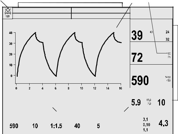
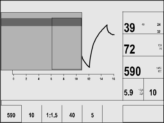
Ventilator screen
1 |
2 |
3 |
4 |
|
O2% low
TVexp low
Ppeak |
cmH2O |
Paw |
Pmean |
|
|
|
Ppause |
O2 |
% |
TVexp |
ml |
|
|
|
|
|
|
|
|
Time (sec) |
|
|
|
|
|
|
MV |
l/min |
RR |
/min |
|
||
|
|
|
|
|
|
|
|
|
|
|
|
|
|
|
|
||||||
11 |
|
Push the knob to confirm the change. Turn the |
|
|
|
|
|
|
|
|
|
|
|
|
|||||||
|
|
|
|
|
|
|
|
|
|
|
|
|
|||||||||
10 |
|
knob to change the setting. |
|
|
|
|
|
|
|
|
|
|
|
|
|
|
|
||||
|
|
|
|
|
|
|
|
|
|
|
|
|
|
|
|
|
|
|
|
|
|
|
|
|
|
|
|
|
|
|
|
|
|
|
|
|
|
|
|
|
|||
9 |
|
Vent On |
|
|
VCV - Volume Control |
|
|
Circle |
Fresh Gas Flow |
l/min |
|
||||||||||
|
|
|
|
|
|
||||||||||||||||
|
|
|
TV |
|
RR |
|
I:E |
|
Pmax |
|
PEEP |
More |
O2 |
|
|
|
|
|
|||
|
|
|
|
|
|
|
|
|
|
|
|||||||||||
|
|
|
|
|
|
|
|
|
|
|
|
Air |
|
|
|
|
|
||||
|
|
|
ml |
|
/min |
|
|
|
cmH2O |
|
cmH2O |
Settings |
N2O |
|
|
Total |
|
||||
|
|
|
|
|
|
|
|
|
|
|
|
|
|
|
|
|
|
|
|
|
|
|
|
|
|
|
|
|
|
|
|
|
|
|
|
|
|
|
|
|
|
|
|
|
|
|
|
|
|
|
|
8 |
|
|
|
|
|
|
|
|
|
|
|
|
|
1. |
Alarm silence indicator and countdown clock |
7. Total flow sensing (optional) |
|
|
|
|
|
||||||||||||||
2. |
Alarm message areas |
|
|
|
8. |
Ventilator settings |
|
|
|
|
|
|
|||||||||
3. |
Waveform area |
|
|
|
|
|
9. |
Mechanical ventilation status |
|
|
|
|
|
||||||||
4. |
Alarm limit settings |
|
|
|
|
|
10. Ventilation mode |
|
|
|
|
|
|
||||||||
5. |
Measured values area |
|
|
|
11. User message area |
|
|
|
|
|
|
||||||||||
6. |
Circuit type |
|
|
|
|
|
|
|
|
|
|
|
|
|
|
|
|
|
|||
Figure 2-7 • Normal view
5
6
7
AC.20.004
M1132382 |
2-13 |
Aespire View
Using menus
Main Menu |
|
|
|
|
Ppeak |
|
|
cmH2O |
Ventilation Mode |
|
VCV |
|
|
|
Pmean |
||
Alarm Setup |
|
|
PCV |
|
|
|
||
|
|
|
|
|
Ppause |
|||
Setup/Calibration |
|
SIMV/PSV |
|
|
|
|||
|
|
O2 |
|
|
% |
|||
Screen and Audio Setup |
|
PSVPro |
|
|
|
|||
|
|
|
|
|
|
|||
Cardiac Bypass |
|
|
SIMV-PC |
|
|
|
|
|
Normal Screen |
|
|
|
|
TVexp |
|
|
ml |
|
|
|
|
|
|
|
|
|
|
|
|
Time (sec) |
|
MV |
l/min |
RR |
/min |
Vent On |
|
|
VCV - Volume Control |
|
|
|
Circle |
|
TV |
RR |
I:E |
Pmax |
PEEP |
More |
|
|
AC.20.009 |
|
|
|
|
|
|
|
||
ml |
/min |
|
cmH2O |
cmH2O |
Settings |
|
|
|
Figure 2-8 • Menu example |
|
|
|
|
|
|
|
|
1.Push the Menu key to show the Main Menu.
2.Turn the ComWheel counterclockwise to highlight the next menu item. Turn the ComWheel clockwise to highlight the previous menu item.
3.Push the ComWheel to enter the highlighted window or a sub menu.
4.Turn the ComWheel clockwise or counterclockwise to highlight the desired selection.
5.Push the ComWheel to confirm the selection.
6.Push the Menu key to exit the menu and return to the normal monitoring screen.
2-14 |
M1132382 |
Loading...