


 Loading...
Aisys Anesthesia Machine
Technical Reference Manual
Aisys
Datex-Ohmeda, Inc., a General Electric Company, doing business as GE Healthcare.
Datex-Ohmeda products have unit serial numbers with coded logic which indicates a product group code, the year of manufacture, and a sequential unit number for identification. The serial number can be in one of two formats.
A A A X 11111 |
A A A X X 111111 A A |
|
|
The X represents an alpha character |
The X X represents a number indicating |
indicating the year the product was |
the year the product was manufactured; |
manufactured; H = 2004, J = 2005, etc. |
04 = 2004, 05 = 2005, etc. |
I and O are not used. |
|
|
|
Aisys and Aladin2 are registered trademarks of Datex-Ohmeda, Inc.
Other brand names or product names used in this manual are trademarks or registered trademarks of their respective holders.
04/08 M1046983
Technical Reference Manual
Aisys Anesthesia Machine
This document is not to be reproduced in any manner, nor are the contents to be disclosed to anyone, without the express authorization of the product service department, Datex-Ohmeda, Ohmeda Drive, PO Box 7550, Madison, Wisconsin, 53707.
© 2008 Datex-Ohmeda Inc.
M1046983 04/08 |
i |
Aisys
Important
The information contained in this Technical Reference manual pertains only to those models of products which are marketed by Datex-Ohmeda as of the effective date of this manual or the latest revision thereof. This Technical Reference manual was prepared for exclusive use by Datex-Ohmeda service personnel in light of their training and experience as well as the availability to them of parts, proper tools and test equipment. Consequently, Datex-Ohmeda provides this Technical Reference manual to its customers purely as a business convenience and for the customer's general information only without warranty of the results with respect to any application of such information. Furthermore, because of the wide variety of circumstances under which maintenance and repair activities may be performed and the unique nature of each individual's own experience, capacity, and qualifications, the fact that customer has received such information from Datex-Ohmeda does not imply in anyway that DatexOhmeda deems said individual to be qualified to perform any such maintenance or repair service. Moreover, it should not be assumed that every acceptable test and safety procedure or method, precaution, tool, equipment or device is referred to within, or that abnormal or unusual circumstances, may not warrant or suggest different or additional procedures or requirements.
This manual is subject to periodic review, update and revision. Customers are cautioned to obtain and consult the latest revision before undertaking any service of the equipment. Comments and suggestions on this manual are invited from our customers. Send your comments and suggestions to the Manager of Technical Communications, Datex-Ohmeda, Ohmeda Drive, PO Box 7550, Madison, Wisconsin 53707.
wCAUTION Servicing of this product in accordance with this Technical Reference manual should never be undertaken in the absence of proper tools, test equipment and the most recent revision to this service manual which is clearly and thoroughly understood.
Technical Competence
The procedures described in this Technical Reference manual should be performed by trained and authorized personnel only. Maintenance should only be undertaken by competent individuals who have a general knowledge of and experience with devices of this nature. No repairs should ever be undertaken or attempted by anyone not having such qualifications.
Datex-Ohmeda strongly recommends using only genuine replacement parts, manufactured or sold by Datex-Ohmeda for all repair parts replacements.
Read completely through each step in every procedure before starting the procedure; any exceptions may result in a failure to properly and safely complete the attempted procedure.
ii |
04/08 M1046983 |
Table of Contents
Important . . . . . . . . . . . . . . . . . . . . . . . . . . . . . . . . . . . . . . . . . . . . . . . . . . . . . . . . . . . . . . . . . . . . . . ii
Technical Competence . . . . . . . . . . . . . . . . . . . . . . . . . . . . . . . . . . . . . . . . . . . . . . . . . . . . . . . . . . . ii
1 Introduction
1.1 What this manual includes . . . . . . . . . . . . . . . . . . . . . . . . . . . . . . . . . . . . . . . . . . . . . . . . . . .1-2 1.2 User’s Reference manuals . . . . . . . . . . . . . . . . . . . . . . . . . . . . . . . . . . . . . . . . . . . . . . . . . . .1-2 1.3 Overview . . . . . . . . . . . . . . . . . . . . . . . . . . . . . . . . . . . . . . . . . . . . . . . . . . . . . . . . . . . . . . . . . .1-3 1.4 Anesthesia system components . . . . . . . . . . . . . . . . . . . . . . . . . . . . . . . . . . . . . . . . . . . . . .1-4 1.5 Breathing system components . . . . . . . . . . . . . . . . . . . . . . . . . . . . . . . . . . . . . . . . . . . . . . . .1-6
1.5.1 Optional system components. . . . . . . . . . . . . . . . . . . . . . . . . . . . . . . . . . . . . . . . . . 1-7 1.6 Display controls . . . . . . . . . . . . . . . . . . . . . . . . . . . . . . . . . . . . . . . . . . . . . . . . . . . . . . . . . . . .1-8 1.7 Anesthesia system display . . . . . . . . . . . . . . . . . . . . . . . . . . . . . . . . . . . . . . . . . . . . . . . . . . .1-9 1.7.1 Using menus . . . . . . . . . . . . . . . . . . . . . . . . . . . . . . . . . . . . . . . . . . . . . . . . . . . . . . 1-11 1.8 Symbols used in the manual or on the equipment . . . . . . . . . . . . . . . . . . . . . . . . . . . . . . 1-12
M1046983 04/08 |
iii |
Aisys
2 Theory of Operation
2.1 Electrical system . . . . . . . . . . . . . . . . . . . . . . . . . . . . . . . . . . . . . . . . . . . . . . . . . . . . . . . . . . .2-2
2.2 Power subsystem . . . . . . . . . . . . . . . . . . . . . . . . . . . . . . . . . . . . . . . . . . . . . . . . . . . . . . . . . .2-4
2.2.1 U-Frame Power Supply . . . . . . . . . . . . . . . . . . . . . . . . . . . . . . . . . . . . . . . . . . . . . . . .2-5 2.2.2 Power Controller board overview . . . . . . . . . . . . . . . . . . . . . . . . . . . . . . . . . . . . . . . .2-5 2.2.3 Power distribution . . . . . . . . . . . . . . . . . . . . . . . . . . . . . . . . . . . . . . . . . . . . . . . . . . . .2-6 2.2.4 Power Controller Board . . . . . . . . . . . . . . . . . . . . . . . . . . . . . . . . . . . . . . . . . . . . . . .2-7 2.3 Display Unit . . . . . . . . . . . . . . . . . . . . . . . . . . . . . . . . . . . . . . . . . . . . . . . . . . . . . . . . . . . . . 2-10
2.4 System communications . . . . . . . . . . . . . . . . . . . . . . . . . . . . . . . . . . . . . . . . . . . . . . . . . . |
2-11 |
2.4.1 Software Power On Self Tests (POST) . . . . . . . . . . . . . . . . . . . . . . . . . . . . . . . . . . . 2-12 2.5 System connections . . . . . . . . . . . . . . . . . . . . . . . . . . . . . . . . . . . . . . . . . . . . . . . . . . . . . . 2-14
2.5.1 Display Unit . . . . . . . . . . . . . . . . . . . . . . . . . . . . . . . . . . . . . . . . . . . . . . . . . . . . . . . 2-14 2.5.2 Display Connector board . . . . . . . . . . . . . . . . . . . . . . . . . . . . . . . . . . . . . . . . . . . . 2-14 2.6 Power Controller and Anesthesia Control board connections . . . . . . . . . . . . . . . . . . . . . 2-15
2.7 Anesthesia Control board . . . . . . . . . . . . . . . . . . . . . . . . . . . . . . . . . . . . . . . . . . . . . . . . . . 2-16
2.7.1 Overview . . . . . . . . . . . . . . . . . . . . . . . . . . . . . . . . . . . . . . . . . . . . . . . . . . . . . . . . . 2-16 2.7.2 Anesthesia Control Board details . . . . . . . . . . . . . . . . . . . . . . . . . . . . . . . . . . . . . 2-18 2.8 Ventilator Interface board . . . . . . . . . . . . . . . . . . . . . . . . . . . . . . . . . . . . . . . . . . . . . . . . . . 2-22
2.9 Electronic Gas Mixer . . . . . . . . . . . . . . . . . . . . . . . . . . . . . . . . . . . . . . . . . . . . . . . . . . . . . . |
2-24 |
2.9.1 Electronic Gas Mixer (details) . . . . . . . . . . . . . . . . . . . . . . . . . . . . . . . . . . . . . . . . |
2-26 |
2.10 Electronic Vaporizer . . . . . . . . . . . . . . . . . . . . . . . . . . . . . . . . . . . . . . . . . . . . . . . . . . . . . |
2-28 |
2.10.1 Agent cassette . . . . . . . . . . . . . . . . . . . . . . . . . . . . . . . . . . . . . . . . . . . . . . . . . . . 2-28 2.10.2 Electronic Vaporizer subsystem (eVap) . . . . . . . . . . . . . . . . . . . . . . . . . . . . . . . 2-30 2.10.3 Agent Delivery board LED indicators . . . . . . . . . . . . . . . . . . . . . . . . . . . . . . . . . . 2-34 2.11 Gas flow through the anesthesia machine . . . . . . . . . . . . . . . . . . . . . . . . . . . . . . . . . . . 2-36
2.11.1 Overview . . . . . . . . . . . . . . . . . . . . . . . . . . . . . . . . . . . . . . . . . . . . . . . . . . . . . . . . 2-36 2.11.2 Electronic vaporizer . . . . . . . . . . . . . . . . . . . . . . . . . . . . . . . . . . . . . . . . . . . . . . . 2-38 2.11.3 Physical connections (O2 supply) . . . . . . . . . . . . . . . . . . . . . . . . . . . . . . . . . . . . 2-42 2.11.4 Physical connections (N2O and Air supplies) . . . . . . . . . . . . . . . . . . . . . . . . . . 2-43 2.11.5 Suction regulators . . . . . . . . . . . . . . . . . . . . . . . . . . . . . . . . . . . . . . . . . . . . . . . . 2-44
2.12 Flow through the breathing system . . . . . . . . . . . . . . . . . . . . . . . . . . . . . . . . . . . . . . . . . 2-45
2.12.1 Overview of flow paths . . . . . . . . . . . . . . . . . . . . . . . . . . . . . . . . . . . . . . . . . . . . . 2-45 2.12.2 Manual ventilation . . . . . . . . . . . . . . . . . . . . . . . . . . . . . . . . . . . . . . . . . . . . . . . . 2-46 2.12.3 Mechanical ventilation . . . . . . . . . . . . . . . . . . . . . . . . . . . . . . . . . . . . . . . . . . . . . 2-49 2.12.4 Fresh gas and O2 flush flow (with SCGO). . . . . . . . . . . . . . . . . . . . . . . . . . . . . . . 2-56 2.12.5 Fresh gas and O2 flush flow (with ACGO). . . . . . . . . . . . . . . . . . . . . . . . . . . . . . . 2-58
iv |
04/08 M1046983 |
Table of Contents
2.13 Ventilator mechanical subsystems . . . . . . . . . . . . . . . . . . . . . . . . . . . . . . . . . . . . . . . . . |
2-60 |
2.13.1 Drive gas filter and Gas Inlet Valve . . . . . . . . . . . . . . . . . . . . . . . . . . . . . . . . . . . 2-60 2.13.2 Pressure regulator . . . . . . . . . . . . . . . . . . . . . . . . . . . . . . . . . . . . . . . . . . . . . . . . 2-61 2.13.3 Flow control valve . . . . . . . . . . . . . . . . . . . . . . . . . . . . . . . . . . . . . . . . . . . . . . . . . 2-61 2.13.4 Drive Gas Check Valve (DGCV) . . . . . . . . . . . . . . . . . . . . . . . . . . . . . . . . . . . . . . 2-62 2.13.5 Bellows Pressure Relief Valve . . . . . . . . . . . . . . . . . . . . . . . . . . . . . . . . . . . . . . . 2-62 2.13.6 Exhalation valve . . . . . . . . . . . . . . . . . . . . . . . . . . . . . . . . . . . . . . . . . . . . . . . . . . 2-63 2.13.7 Mechanical Overpressure Valve . . . . . . . . . . . . . . . . . . . . . . . . . . . . . . . . . . . . . 2-64 2.13.8 Reservoir and bleed resistor . . . . . . . . . . . . . . . . . . . . . . . . . . . . . . . . . . . . . . . . 2-64 2.13.9 Free breathing valve . . . . . . . . . . . . . . . . . . . . . . . . . . . . . . . . . . . . . . . . . . . . . . . 2-65 2.13.10 Breathing circuit flow sensors . . . . . . . . . . . . . . . . . . . . . . . . . . . . . . . . . . . . . . 2-66
3 Checkout Procedure
3.1 Inspect the system . . . . . . . . . . . . . . . . . . . . . . . . . . . . . . . . . . . . . . . . . . . . . . . . . . . . . . . . .3-2
3.2 System checkout . . . . . . . . . . . . . . . . . . . . . . . . . . . . . . . . . . . . . . . . . . . . . . . . . . . . . . . . . . .3-2
3.2.1 Leak < 250 ml . . . . . . . . . . . . . . . . . . . . . . . . . . . . . . . . . . . . . . . . . . . . . . . . . . . . . . .3-2 3.2.2 Machine Check . . . . . . . . . . . . . . . . . . . . . . . . . . . . . . . . . . . . . . . . . . . . . . . . . . . . . .3-3 3.2.3 Machine Check - System (Ventilator Circuit Testing) . . . . . . . . . . . . . . . . . . . . . . . .3-3 3.2.4 Machine Check - Circuit (Bag Circuit Testing) . . . . . . . . . . . . . . . . . . . . . . . . . . . . . .3-3 3.2.5 Machine Check - Circuit O2 . . . . . . . . . . . . . . . . . . . . . . . . . . . . . . . . . . . . . . . . . . . .3-4
3.3 Individual Checks . . . . . . . . . . . . . . . . . . . . . . . . . . . . . . . . . . . . . . . . . . . . . . . . . . . . . . . . . .3-4
3.3.1 System . . . . . . . . . . . . . . . . . . . . . . . . . . . . . . . . . . . . . . . . . . . . . . . . . . . . . . . . . . . . .3-4 3.3.2 Circuit . . . . . . . . . . . . . . . . . . . . . . . . . . . . . . . . . . . . . . . . . . . . . . . . . . . . . . . . . . . . .3-5 3.3.3 Circuit O2 Cell . . . . . . . . . . . . . . . . . . . . . . . . . . . . . . . . . . . . . . . . . . . . . . . . . . . . . . .3-5 3.3.4 Low P Leak . . . . . . . . . . . . . . . . . . . . . . . . . . . . . . . . . . . . . . . . . . . . . . . . . . . . . . . . .3-5 3.3.5 Low P Leak (machines with ACGO) . . . . . . . . . . . . . . . . . . . . . . . . . . . . . . . . . . . . . .3-6 3.3.6 Agent Delivery . . . . . . . . . . . . . . . . . . . . . . . . . . . . . . . . . . . . . . . . . . . . . . . . . . . . . . .3-6
3.4 Bellows drop test . . . . . . . . . . . . . . . . . . . . . . . . . . . . . . . . . . . . . . . . . . . . . . . . . . . . . . . . . . .3-7
3.5 Backlight test . . . . . . . . . . . . . . . . . . . . . . . . . . . . . . . . . . . . . . . . . . . . . . . . . . . . . . . . . . . . . .3-7
3.6 Pipeline and cylinder tests . . . . . . . . . . . . . . . . . . . . . . . . . . . . . . . . . . . . . . . . . . . . . . . . . . .3-8
3.6.1 O2 supply alarm test . . . . . . . . . . . . . . . . . . . . . . . . . . . . . . . . . . . . . . . . . . . . . . . . . .3-8 3.7 Flush Flow Test . . . . . . . . . . . . . . . . . . . . . . . . . . . . . . . . . . . . . . . . . . . . . . . . . . . . . . . . . . . . .3-9
3.8 Alarm tests . . . . . . . . . . . . . . . . . . . . . . . . . . . . . . . . . . . . . . . . . . . . . . . . . . . . . . . . . . . . . . 3-10
3.9 Alternate O2 flowmeter tests . . . . . . . . . . . . . . . . . . . . . . . . . . . . . . . . . . . . . . . . . . . . . . . |
3-11 |
3.10 Auxiliary O2 flowmeter tests . . . . . . . . . . . . . . . . . . . . . . . . . . . . . . . . . . . . . . . . . . . . . . . 3-11
3.11 Integrated Suction Regulator tests . . . . . . . . . . . . . . . . . . . . . . . . . . . . . . . . . . . . . . . . . |
3-11 |
3.12 Power failure test . . . . . . . . . . . . . . . . . . . . . . . . . . . . . . . . . . . . . . . . . . . . . . . . . . . . . . . |
3-12 |
3.13 Electrical safety tests . . . . . . . . . . . . . . . . . . . . . . . . . . . . . . . . . . . . . . . . . . . . . . . . . . . . |
3-12 |
M1046983 04/08 |
v |
Aisys
4 Install/Service Menus
4.1 Service and Installation menu structure . . . . . . . . . . . . . . . . . . . . . . . . . . . . . . . . . . . . . . |
. .4-2 |
4.2 Install/Service Menu (Super User) . . . . . . . . . . . . . . . . . . . . . . . . . . . . . . . . . . . . . . . . . . . . |
.4-3 |
4.2.1 Trends Setup . . . . . . . . . . . . . . . . . . . . . . . . . . . . . . . . . . . . . . . . . . . . . . . . . . . . . . . |
.4-5 |
4.2.2 Colors and Units Menu . . . . . . . . . . . . . . . . . . . . . . . . . . . . . . . . . . . . . . . . . . . . . . . |
.4-6 |
4.2.3 Cumulative Usage . . . . . . . . . . . . . . . . . . . . . . . . . . . . . . . . . . . . . . . . . . . . . . . . . . |
.4-7 |
4.2.4 Factory Defaults . . . . . . . . . . . . . . . . . . . . . . . . . . . . . . . . . . . . . . . . . . . . . . . . . . . . |
.4-8 |
4.2.5 Parameter Settings . . . . . . . . . . . . . . . . . . . . . . . . . . . . . . . . . . . . . . . . . . . . . . . . . |
4-10 |
4.2.6 Fresh Gas Controls . . . . . . . . . . . . . . . . . . . . . . . . . . . . . . . . . . . . . . . . . . . . . . . . . |
4-10 |
4.2.7 VCV Cardiac Bypass . . . . . . . . . . . . . . . . . . . . . . . . . . . . . . . . . . . . . . . . . . . . . . . . |
4-10 |
4.3 Installation Menu . . . . . . . . . . . . . . . . . . . . . . . . . . . . . . . . . . . . . . . . . . . . . . . . . . . . . . . . |
4-11 |
4.3.1 Configuration . . . . . . . . . . . . . . . . . . . . . . . . . . . . . . . . . . . . . . . . . . . . . . . . . . . . . |
4-12 |
4.3.2 Configuration Units . . . . . . . . . . . . . . . . . . . . . . . . . . . . . . . . . . . . . . . . . . . . . . . . . |
4-13 |
4.3.3 Options Key . . . . . . . . . . . . . . . . . . . . . . . . . . . . . . . . . . . . . . . . . . . . . . . . . . . . . . . |
4-13 |
4.3.4 Copy Configuration . . . . . . . . . . . . . . . . . . . . . . . . . . . . . . . . . . . . . . . . . . . . . . . . . |
4-14 |
4.4 Service Menu . . . . . . . . . . . . . . . . . . . . . . . . . . . . . . . . . . . . . . . . . . . . . . . . . . . . . . . . . . . . |
4-15 |
4.4.1 Software/Hardware Ver Menu . . . . . . . . . . . . . . . . . . . . . . . . . . . . . . . . . . . . . . . . |
4-16 |
4.4.2 Service Log Menu . . . . . . . . . . . . . . . . . . . . . . . . . . . . . . . . . . . . . . . . . . . . . . . . . . |
4-17 |
4.5 Calibration . . . . . . . . . . . . . . . . . . . . . . . . . . . . . . . . . . . . . . . . . . . . . . . . . . . . . . . . . . . . . . |
4-18 |
4.5.1 Spiro Calibration . . . . . . . . . . . . . . . . . . . . . . . . . . . . . . . . . . . . . . . . . . . . . . . . . . . |
4-19 |
4.5.2 User Calibration menu . . . . . . . . . . . . . . . . . . . . . . . . . . . . . . . . . . . . . . . . . . . . . . |
4-20 |
4.5.3 Manifold P Span . . . . . . . . . . . . . . . . . . . . . . . . . . . . . . . . . . . . . . . . . . . . . . . . . . . |
4-21 |
4.5.4 Insp Flow Zero . . . . . . . . . . . . . . . . . . . . . . . . . . . . . . . . . . . . . . . . . . . . . . . . . . . . . |
4-22 |
4.5.5 Inspiratory Flow Valve . . . . . . . . . . . . . . . . . . . . . . . . . . . . . . . . . . . . . . . . . . . . . . . |
4-23 |
4.5.6 Bleed Resistor . . . . . . . . . . . . . . . . . . . . . . . . . . . . . . . . . . . . . . . . . . . . . . . . . . . . . |
4-24 |
4.5.7 Paw Span . . . . . . . . . . . . . . . . . . . . . . . . . . . . . . . . . . . . . . . . . . . . . . . . . . . . . . . . |
4-25 |
4.5.8 Zero Gas Xducrs . . . . . . . . . . . . . . . . . . . . . . . . . . . . . . . . . . . . . . . . . . . . . . . . . . . |
4-26 |
4.5.9 Cal Config . . . . . . . . . . . . . . . . . . . . . . . . . . . . . . . . . . . . . . . . . . . . . . . . . . . . . . . . |
4-27 |
4.5.10 Mixer P Zero . . . . . . . . . . . . . . . . . . . . . . . . . . . . . . . . . . . . . . . . . . . . . . . . . . . . . |
4-28 |
5 Calibration
5.1 Primary Regulators . . . . . . . . . . . . . . . . . . . . . . . . . . . . . . . . . . . . . . . . . . . . . . . . . . . . . . . |
. .5-2 |
5.1.1 Test setup . . . . . . . . . . . . . . . . . . . . . . . . . . . . . . . . . . . . . . . . . . . . . . . . . . . . . . . . |
. .5-3 |
5.1.2 Testing Primary Regulators . . . . . . . . . . . . . . . . . . . . . . . . . . . . . . . . . . . . . . . . . . |
. .5-3 |
5.1.3 Adjusting Primary Regulators . . . . . . . . . . . . . . . . . . . . . . . . . . . . . . . . . . . . . . . . . . |
.5-8 |
5.2 O2 Flush Regulator . . . . . . . . . . . . . . . . . . . . . . . . . . . . . . . . . . . . . . . . . . . . . . . . . . . . . . . . |
.5-9 |
5.3 Adjust Drive Gas Regulator . . . . . . . . . . . . . . . . . . . . . . . . . . . . . . . . . . . . . . . . . . . . . . . . . |
5-10 |
5.4 Ventilator Calibrations . . . . . . . . . . . . . . . . . . . . . . . . . . . . . . . . . . . . . . . . . . . . . . . . . . . . |
5-11 |
5.4.1 Cal Config . . . . . . . . . . . . . . . . . . . . . . . . . . . . . . . . . . . . . . . . . . . . . . . . . . . . . . . . |
5-12 |
5.4.2 Manifold P Span . . . . . . . . . . . . . . . . . . . . . . . . . . . . . . . . . . . . . . . . . . . . . . . . . . . |
5-13 |
5.4.3 Inspiratory Flow Valve Cal . . . . . . . . . . . . . . . . . . . . . . . . . . . . . . . . . . . . . . . . . . . . |
5-14 |
5.4.4 Insp Flow Zero . . . . . . . . . . . . . . . . . . . . . . . . . . . . . . . . . . . . . . . . . . . . . . . . . . . . . |
5-16 |
5.4.5 Bleed Resistor Cal . . . . . . . . . . . . . . . . . . . . . . . . . . . . . . . . . . . . . . . . . . . . . . . . . . |
5-17 |
5.4.6 Paw Span . . . . . . . . . . . . . . . . . . . . . . . . . . . . . . . . . . . . . . . . . . . . . . . . . . . . . . . . . |
5-18 |
vi |
04/08 M1046983 |
Table of Contents
6 Installation and Maintenance
6.1 Aisys Installation Checklist . . . . . . . . . . . . . . . . . . . . . . . . . . . . . . . . . . . . . . . . . . . . . . . . . . .6-2
6.2 Aisys Planned Maintenance . . . . . . . . . . . . . . . . . . . . . . . . . . . . . . . . . . . . . . . . . . . . . . . . . .6-4
6.2.1 Every twelve (12) months . . . . . . . . . . . . . . . . . . . . . . . . . . . . . . . . . . . . . . . . . . . . |
. .6-4 |
6.2.2 Every twenty-four (24) months . . . . . . . . . . . . . . . . . . . . . . . . . . . . . . . . . . . . . . . . |
.6-5 |
6.2.3 Every forty-eight (48) months . . . . . . . . . . . . . . . . . . . . . . . . . . . . . . . . . . . . . . . . . |
.6-5 |
6.3 Free breathing valve maintenance . . . . . . . . . . . . . . . . . . . . . . . . . . . . . . . . . . . . . . . . . . . . |
.6-6 |
6.4 MOPV pressure relief valve test . . . . . . . . . . . . . . . . . . . . . . . . . . . . . . . . . . . . . . . . . . . . . . |
.6-7 |
6.4.1 Test setup . . . . . . . . . . . . . . . . . . . . . . . . . . . . . . . . . . . . . . . . . . . . . . . . . . . . . . . . . |
.6-7 |
6.4.2 Test procedure . . . . . . . . . . . . . . . . . . . . . . . . . . . . . . . . . . . . . . . . . . . . . . . . . . . . . |
.6-7 |
6.5 Pressure Limit Circuit test . . . . . . . . . . . . . . . . . . . . . . . . . . . . . . . . . . . . . . . . . . . . . . . . . . . |
.6-8 |
6.6 Mixer test . . . . . . . . . . . . . . . . . . . . . . . . . . . . . . . . . . . . . . . . . . . . . . . . . . . . . . . . . . . . . . . |
6-10 |
6.6.1 Mixer outlet check valve leak test . . . . . . . . . . . . . . . . . . . . . . . . . . . . . . . . . . . . . 6-10 6.6.2 Mixer flow verification . . . . . . . . . . . . . . . . . . . . . . . . . . . . . . . . . . . . . . . . . . . . . . . 6-10 6.7 Alternate O2 flowmeter tests . . . . . . . . . . . . . . . . . . . . . . . . . . . . . . . . . . . . . . . . . . . . . . . 6-11
6.8 Auxiliary O2 flowmeter tests . . . . . . . . . . . . . . . . . . . . . . . . . . . . . . . . . . . . . . . . . . . . . . . . |
6-12 |
6.9 Integrated Suction Regulator tests . . . . . . . . . . . . . . . . . . . . . . . . . . . . . . . . . . . . . . . . . . |
6-13 |
6.10 Battery capacity test . . . . . . . . . . . . . . . . . . . . . . . . . . . . . . . . . . . . . . . . . . . . . . . . . . . . . 6-15
6.11 Cable routing, upper module rack . . . . . . . . . . . . . . . . . . . . . . . . . . . . . . . . . . . . . . . . . . 6-16
6.11.1 Display Unit and Anesthesia Monitor . . . . . . . . . . . . . . . . . . . . . . . . . . . . . . . . . 6-17 6.11.2 Display arm . . . . . . . . . . . . . . . . . . . . . . . . . . . . . . . . . . . . . . . . . . . . . . . . . . . . . . 6-17 6.11.3 Left-side cable route . . . . . . . . . . . . . . . . . . . . . . . . . . . . . . . . . . . . . . . . . . . . . . . 6-18 6.11.4 Upper left-side cable route. . . . . . . . . . . . . . . . . . . . . . . . . . . . . . . . . . . . . . . . . . 6-18 6.11.5 Front side of Display Connector Board . . . . . . . . . . . . . . . . . . . . . . . . . . . . . . . . 6-18 6.11.6 Upper module rack . . . . . . . . . . . . . . . . . . . . . . . . . . . . . . . . . . . . . . . . . . . . . . . . 6-19 6.11.7 Rear cosmetic panel . . . . . . . . . . . . . . . . . . . . . . . . . . . . . . . . . . . . . . . . . . . . . . . 6-19 6.11.8 Additional cable access points to upper chassis . . . . . . . . . . . . . . . . . . . . . . . . 6-19
6.12 Cable routing, lower module rack . . . . . . . . . . . . . . . . . . . . . . . . . . . . . . . . . . . . . . . . . . 6-20
6.12.1 Display Unit and Anesthesia Monitor . . . . . . . . . . . . . . . . . . . . . . . . . . . . . . . . . 6-21 6.12.2 Display arm . . . . . . . . . . . . . . . . . . . . . . . . . . . . . . . . . . . . . . . . . . . . . . . . . . . . . . 6-21 6.12.3 Left-side cable route . . . . . . . . . . . . . . . . . . . . . . . . . . . . . . . . . . . . . . . . . . . . . . . 6-22 6.12.4 Front side of Display Connector Board and lower module rack. . . . . . . . . . . . . 6-22 6.12.5 Rear cable route . . . . . . . . . . . . . . . . . . . . . . . . . . . . . . . . . . . . . . . . . . . . . . . . . . 6-23 6.12.6 Right-side cable route . . . . . . . . . . . . . . . . . . . . . . . . . . . . . . . . . . . . . . . . . . . . . 6-24
M1046983 04/08 |
vii |
Aisys
7 Troubleshooting
7.1 Troubleshooting Guidelines . . . . . . . . . . . . . . . . . . . . . . . . . . . . . . . . . . . . . . . . . . . . . . . . . .7-2
7.2 Troubleshooting high pressure and low pressure leaks . . . . . . . . . . . . . . . . . . . . . . . . . . . .7-3
7.3 Troubleshooting Startup Screen (POST) messages - for HPDU . . . . . . . . . . . . . . . . . . . . . .7-4
7.4 Troubleshooting the HPDU Display . . . . . . . . . . . . . . . . . . . . . . . . . . . . . . . . . . . . . . . . . . . .7-5
7.5 Troubleshooting System Malfunction (safe-state) screen . . . . . . . . . . . . . . . . . . . . . . . . . .7-6
7.6 Breathing System Leak Test Guide . . . . . . . . . . . . . . . . . . . . . . . . . . . . . . . . . . . . . . . . . . . . .7-7
7.6.1 Check Valves . . . . . . . . . . . . . . . . . . . . . . . . . . . . . . . . . . . . . . . . . . . . . . . . . . . . . . |
. .7-8 |
7.6.2 Breathing System Troubleshooting Flowcharts . . . . . . . . . . . . . . . . . . . . . . . . . . . |
. 7-9 |
7.6.3 Leak Isolation Tests . . . . . . . . . . . . . . . . . . . . . . . . . . . . . . . . . . . . . . . . . . . . . . . . |
7-14 |
7.7 System Troubleshooting Flowcharts . . . . . . . . . . . . . . . . . . . . . . . . . . . . . . . . . . . . . . . . . |
7-29 |
7.8 System Malfunction and Alt O2 Flowchart Table . . . . . . . . . . . . . . . . . . . . . . . . . . . . . . . |
7-41 |
7.9 Technical Alarms . . . . . . . . . . . . . . . . . . . . . . . . . . . . . . . . . . . . . . . . . . . . . . . . . . . . . . . . . |
7-43 |
7.10 Electronic Vaporizer (eVap) Troubleshooting . . . . . . . . . . . . . . . . . . . . . . . . . . . . . . . . . |
7-78 |
7.10.1 Vaporizer Test Results . . . . . . . . . . . . . . . . . . . . . . . . . . . . . . . . . . . . . . . . . . . . . |
7-78 |
7.10.2 Vaporizer Test Results troubleshooting procedures . . . . . . . . . . . . . . . . . . . . . . |
7-79 |
7.10.3 eVap Troubleshooting Flowchart . . . . . . . . . . . . . . . . . . . . . . . . . . . . . . . . . . . . . |
7-83 |
7.10.4 eVap Error Log table . . . . . . . . . . . . . . . . . . . . . . . . . . . . . . . . . . . . . . . . . . . . . . . |
7-84 |
7.10.5 eVap Flow and Zero troubleshooting . . . . . . . . . . . . . . . . . . . . . . . . . . . . . . . . . . |
7-85 |
7.10.6 eVap Pressure troubleshooting . . . . . . . . . . . . . . . . . . . . . . . . . . . . . . . . . . . . . . |
7-86 |
7.10.7 eVap Leak and Cassette troubleshooting . . . . . . . . . . . . . . . . . . . . . . . . . . . . . . |
7-87 |
7.10.8 eVap Communication troubleshooting . . . . . . . . . . . . . . . . . . . . . . . . . . . . . . . . |
7-88 |
7.10.9 eVap ADB troubleshooting . . . . . . . . . . . . . . . . . . . . . . . . . . . . . . . . . . . . . . . . . . |
7-89 |
7.10.10 eVap Temperature troubleshooting. . . . . . . . . . . . . . . . . . . . . . . . . . . . . . . . . . |
7-90 |
7.10.11 eVap Power and Valves troubleshooting. . . . . . . . . . . . . . . . . . . . . . . . . . . . . . |
7-91 |
7.10.12 Electronic vaporizer 10VA power interconnect fault isolation . . . . . . . . . . . . |
7-92 |
7.10.13 Vaporizer Checkout Troubleshooting. . . . . . . . . . . . . . . . . . . . . . . . . . . . . . . . . |
7-93 |
7.11 eVap Therapy Cassette Leak Test . . . . . . . . . . . . . . . . . . . . . . . . . . . . . . . . . . . . . . . . . . |
7-97 |
7.12 eVap Backpressure Valve Test . . . . . . . . . . . . . . . . . . . . . . . . . . . . . . . . . . . . . . . . . . . . . 7-98
7.13 eVap Inflow Check Valve Test . . . . . . . . . . . . . . . . . . . . . . . . . . . . . . . . . . . . . . . . . . . . . 7-100
7.14 eVap Scavenger Path Testing . . . . . . . . . . . . . . . . . . . . . . . . . . . . . . . . . . . . . . . . . . . . . 7-102
7.15 Steps and Messages displayed during the System Checkout . . . . . . . . . . . . . . . . . . . 7-103
8 Software Download and Special Functions
8.1 Overview . . . . . . . . . . . . . . . . . . . . . . . . . . . . . . . . . . . . . . . . . . . . . . . . . . . . . . . . . . . . . . . . . .8-2
8.1.1 Main Menu and System Information . . . . . . . . . . . . . . . . . . . . . . . . . . . . . . . . . . . . .8-2
8.2 Software Download . . . . . . . . . . . . . . . . . . . . . . . . . . . . . . . . . . . . . . . . . . . . . . . . . . . . . . . . .8-3
8.3 Special Functions . . . . . . . . . . . . . . . . . . . . . . . . . . . . . . . . . . . . . . . . . . . . . . . . . . . . . . . . . .8-5
8.3.1 Display Diagnostics . . . . . . . . . . . . . . . . . . . . . . . . . . . . . . . . . . . . . . . . . . . . . . . . . .8-6
8.3.2 Test Keys and Battery . . . . . . . . . . . . . . . . . . . . . . . . . . . . . . . . . . . . . . . . . . . . . . . . .8-7
8.3.3 System Download Log . . . . . . . . . . . . . . . . . . . . . . . . . . . . . . . . . . . . . . . . . . . . . . . .8-8
viii |
04/08 M1046983 |
Table of Contents
9 Repair Procedures
9.1 Circuit board replacement precautions . . . . . . . . . . . . . . . . . . . . . . . . . . . . . . . . . . . . . . . . .9-4
9.2 How to bleed gas pressure from the machine . . . . . . . . . . . . . . . . . . . . . . . . . . . . . . . . . . . .9-5
9.3 How to remove the rear panels . . . . . . . . . . . . . . . . . . . . . . . . . . . . . . . . . . . . . . . . . . . . . . . .9-6
9.3.1 To remove the rear upper panels . . . . . . . . . . . . . . . . . . . . . . . . . . . . . . . . . . . . . . . .9-6 9.3.2 To remove the lower access panels . . . . . . . . . . . . . . . . . . . . . . . . . . . . . . . . . . . . . .9-6 9.4 How to remove the tabletop . . . . . . . . . . . . . . . . . . . . . . . . . . . . . . . . . . . . . . . . . . . . . . . . . .9-7
9.5 Servicing the pan electrical enclosure components . . . . . . . . . . . . . . . . . . . . . . . . . . . . . . .9-8
9.5.1 Ventilator Interface board . . . . . . . . . . . . . . . . . . . . . . . . . . . . . . . . . . . . . . . . . . . |
. .9-8 |
9.5.2 Electronic Gas Mixer assembly . . . . . . . . . . . . . . . . . . . . . . . . . . . . . . . . . . . . . . . . |
.9-9 |
9.6 How to access dashboard components . . . . . . . . . . . . . . . . . . . . . . . . . . . . . . . . . . . . . . |
9-10 |
9.7 Replace electronic vaporizer and components . . . . . . . . . . . . . . . . . . . . . . . . . . . . . . . . . |
9-11 |
9.7.1 Remove the electronic vaporizer . . . . . . . . . . . . . . . . . . . . . . . . . . . . . . . . . . . . . . 9-12 9.7.2 Replacing eVap components . . . . . . . . . . . . . . . . . . . . . . . . . . . . . . . . . . . . . . . . . 9-13 9.8 Servicing Aladin2 cassettes . . . . . . . . . . . . . . . . . . . . . . . . . . . . . . . . . . . . . . . . . . . . . . . . 9-16
9.8.1 Emptying an Aladin2 cassette . . . . . . . . . . . . . . . . . . . . . . . . . . . . . . . . . . . . . . . . 9-16 9.8.2 Aladin2 cassette parts replacement . . . . . . . . . . . . . . . . . . . . . . . . . . . . . . . . . . . 9-17 9.9 Replace Alt O2 components . . . . . . . . . . . . . . . . . . . . . . . . . . . . . . . . . . . . . . . . . . . . . . . . 9-20
9.10 Replace system switch assembly . . . . . . . . . . . . . . . . . . . . . . . . . . . . . . . . . . . . . . . . . . |
9-21 |
9.11 Servicing the High Performance Display Unit . . . . . . . . . . . . . . . . . . . . . . . . . . . . . . . . . |
9-23 |
9.11.1 Remove the Display Unit . . . . . . . . . . . . . . . . . . . . . . . . . . . . . . . . . . . . . . . . . . . |
9-23 |
9.11.2 Disassemble the Display Unit . . . . . . . . . . . . . . . . . . . . . . . . . . . . . . . . . . . . . . . |
9-24 |
9.11.3 CPU Fan . . . . . . . . . . . . . . . . . . . . . . . . . . . . . . . . . . . . . . . . . . . . . . . . . . . . . . . . |
9-24 |
9.11.4 To replace the CPU board . . . . . . . . . . . . . . . . . . . . . . . . . . . . . . . . . . . . . . . . . . |
9-25 |
9.11.5 To replace the LCD display . . . . . . . . . . . . . . . . . . . . . . . . . . . . . . . . . . . . . . . . . |
9-26 |
9.11.6 To replace the backlights . . . . . . . . . . . . . . . . . . . . . . . . . . . . . . . . . . . . . . . . . . . |
9-28 |
9.11.7 To replace the Inverters . . . . . . . . . . . . . . . . . . . . . . . . . . . . . . . . . . . . . . . . . . . . |
9-28 |
9.11.8 To replace the front enclosure or components . . . . . . . . . . . . . . . . . . . . . . . . . . |
9-30 |
9.12 Servicing the lower electrical enclosure components . . . . . . . . . . . . . . . . . . . . . . . . . . |
9-32 |
9.12.1 Power Controller board . . . . . . . . . . . . . . . . . . . . . . . . . . . . . . . . . . . . . . . . . . . . 9-32 9.12.2 Power Supply . . . . . . . . . . . . . . . . . . . . . . . . . . . . . . . . . . . . . . . . . . . . . . . . . . . . 9-33 9.12.3 Anesthesia Control board . . . . . . . . . . . . . . . . . . . . . . . . . . . . . . . . . . . . . . . . . . 9-34 9.12.4 Backup batteries . . . . . . . . . . . . . . . . . . . . . . . . . . . . . . . . . . . . . . . . . . . . . . . . . 9-35 9.13 Servicing the Vent Engine . . . . . . . . . . . . . . . . . . . . . . . . . . . . . . . . . . . . . . . . . . . . . . . . . 9-36
9.13.1 To remove the Vent Engine . . . . . . . . . . . . . . . . . . . . . . . . . . . . . . . . . . . . . . . . . |
9-37 |
9.13.2 Replacing Vent Engine components . . . . . . . . . . . . . . . . . . . . . . . . . . . . . . . . . . |
9-38 |
9.13.3 Replacing GIV components . . . . . . . . . . . . . . . . . . . . . . . . . . . . . . . . . . . . . . . . . |
9-39 |
M1046983 04/08 |
ix |
Aisys
9.14 Servicing the pipeline inlet manifold components . . . . . . . . . . . . . . . . . . . . . . . . . . . . . 9-40
9.14.1 Replace pipeline inlet filter . . . . . . . . . . . . . . . . . . . . . . . . . . . . . . . . . . . . . . . . . 9-40 9.14.2 Replace pipeline inlet check valve . . . . . . . . . . . . . . . . . . . . . . . . . . . . . . . . . . . 9-40 9.14.3 Replace the inlet manifold . . . . . . . . . . . . . . . . . . . . . . . . . . . . . . . . . . . . . . . . . 9-41 9.15 Service the cylinder supply modules . . . . . . . . . . . . . . . . . . . . . . . . . . . . . . . . . . . . . . . . 9-42
9.15.1 Tightening procedure for high-pressure tube fittings . . . . . . . . . . . . . . . . . . . . . 9-42 9.15.2 Replace primary regulator module (complete replacement) . . . . . . . . . . . . . . 9-42 9.15.3 Replace cylinder inlet filter . . . . . . . . . . . . . . . . . . . . . . . . . . . . . . . . . . . . . . . . . 9-43 9.15.4 Replace cylinder check valve . . . . . . . . . . . . . . . . . . . . . . . . . . . . . . . . . . . . . . . 9-43 9.16 Replace gas-supply pressure transducers . . . . . . . . . . . . . . . . . . . . . . . . . . . . . . . . . . . 9-44
9.17 Replace ACGO selector switch . . . . . . . . . . . . . . . . . . . . . . . . . . . . . . . . . . . . . . . . . . . . . |
9-45 |
9.18 Clean or replace ACGO port flapper valve . . . . . . . . . . . . . . . . . . . . . . . . . . . . . . . . . . . . |
9-47 |
9.19 Replace the APL valve . . . . . . . . . . . . . . . . . . . . . . . . . . . . . . . . . . . . . . . . . . . . . . . . . . . |
9-48 |
9.20 Replace the bag support arm . . . . . . . . . . . . . . . . . . . . . . . . . . . . . . . . . . . . . . . . . . . . . . |
9-49 |
9.20.1 Servicing the bag support arm . . . . . . . . . . . . . . . . . . . . . . . . . . . . . . . . . . . . . . |
9-50 |
9.20.2 Replace bag port housing . . . . . . . . . . . . . . . . . . . . . . . . . . . . . . . . . . . . . . . . . . |
9-51 |
9.21 Replace ABS breathing system components . . . . . . . . . . . . . . . . . . . . . . . . . . . . . . . . . |
9-52 |
9.21.1 Replace Bag/Vent switch assembly . . . . . . . . . . . . . . . . . . . . . . . . . . . . . . . . . . 9-52 9.21.2 Replace bellows base latch assembly . . . . . . . . . . . . . . . . . . . . . . . . . . . . . . . . 9-53 9.21.3 EZchange Canister spring replacement. . . . . . . . . . . . . . . . . . . . . . . . . . . . . . . . 9-54 9.22 Replace casters . . . . . . . . . . . . . . . . . . . . . . . . . . . . . . . . . . . . . . . . . . . . . . . . . . . . . . . . . 9-55
9.23 Reconfigure sample gas return line . . . . . . . . . . . . . . . . . . . . . . . . . . . . . . . . . . . . . . . . . 9-56
9.24 Change drive gas . . . . . . . . . . . . . . . . . . . . . . . . . . . . . . . . . . . . . . . . . . . . . . . . . . . . . . . . 9-57
9.25 Display arm adjustments . . . . . . . . . . . . . . . . . . . . . . . . . . . . . . . . . . . . . . . . . . . . . . . . . |
9-58 |
9.25.1 Display arm counterbalance adjustment . . . . . . . . . . . . . . . . . . . . . . . . . . . . . . 9-58 9.25.2 Wrist Casting adjustment . . . . . . . . . . . . . . . . . . . . . . . . . . . . . . . . . . . . . . . . . . 9-59 9.25.3 Clutch bearing adjustment . . . . . . . . . . . . . . . . . . . . . . . . . . . . . . . . . . . . . . . . . 9-59
10 Illustrated Parts
10.1 Service tools . . . . . . . . . . . . . . . . . . . . . . . . . . . . . . . . . . . . . . . . . . . . . . . . . . . . . . . . . . . |
10-3 |
10.1.1 Software tools . . . . . . . . . . . . . . . . . . . . . . . . . . . . . . . . . . . . . . . . . . . . . . . . . . . . 10-3 10.1.2 Manifold pressure test adapter . . . . . . . . . . . . . . . . . . . . . . . . . . . . . . . . . . . . . . 10-3 10.1.3 Test Devices and service tools . . . . . . . . . . . . . . . . . . . . . . . . . . . . . . . . . . . . . . . 10-4 10.1.4 Lubricants and Adhesives . . . . . . . . . . . . . . . . . . . . . . . . . . . . . . . . . . . . . . . . . . 10-4 10.1.5 Test Tools . . . . . . . . . . . . . . . . . . . . . . . . . . . . . . . . . . . . . . . . . . . . . . . . . . . . . . . . 10-5
10.2 Components - front view . . . . . . . . . . . . . . . . . . . . . . . . . . . . . . . . . . . . . . . . . . . . . . . . . . 10-6
10.3 Components - front view references . . . . . . . . . . . . . . . . . . . . . . . . . . . . . . . . . . . . . . . . |
10-7 |
10.4 Components - rear view . . . . . . . . . . . . . . . . . . . . . . . . . . . . . . . . . . . . . . . . . . . . . . . . . . |
10-8 |
10.5 AC Power cords and AC Inlet . . . . . . . . . . . . . . . . . . . . . . . . . . . . . . . . . . . . . . . . . . . . . . |
10-9 |
10.6 AC Inlet/Outlet Components . . . . . . . . . . . . . . . . . . . . . . . . . . . . . . . . . . . . . . . . . . . . . 10-10
10.7 Lower electronic enclosure components . . . . . . . . . . . . . . . . . . . . . . . . . . . . . . . . . . . . 10-12
x |
04/08 M1046983 |
|
Table of Contents |
10.8 Upper (pan) electronic enclosure components . . . . . . . . . . . . . . . . . . |
. . . . . . . . . . . . 10-13 |
10.9 Electronic Gas Mixer . . . . . . . . . . . . . . . . . . . . . . . . . . . . . . . . . . . . . . . . . |
. . . . . . . . . . . 10-14 |
10.10 Pipeline inlet fittings . . . . . . . . . . . . . . . . . . . . . . . . . . . . . . . . . . . . . . . . |
. . . . . . . . . . . 10-15 |
10.11 Cylinder Gas Supplies . . . . . . . . . . . . . . . . . . . . . . . . . . . . . . . . . . . . . . |
. . . . . . . . . . . 10-16 |
10.11.1 Power outlets and third cylinder high-pressure hoses . . . . . . . |
. . . . . . . . . . . 10-17 |
10.11.2 Cylinder inlet fittings. . . . . . . . . . . . . . . . . . . . . . . . . . . . . . . . . . |
. . . . . . . . . . . 10-18 |
10.12 ABS to machine Interface Components (SCGO) . . . . . . . . . . . . . . . . . |
. . . . . . . . . . . 10-19 |
10.13 ABS to machine Interface Components (ACGO) . . . . . . . . . . . . . . . . . |
. . . . . . . . . . . 10-20 |
10.14 O2 Flush Valve . . . . . . . . . . . . . . . . . . . . . . . . . . . . . . . . . . . . . . . . . . . . . |
. . . . . . . . . . . 10-21 |
10.15 Front panel, Alt O2, and system switch . . . . . . . . . . . . . . . . . . . . . . . . . |
. . . . . . . . . . . 10-22 |
10.16 Vent Engine Housing . . . . . . . . . . . . . . . . . . . . . . . . . . . . . . . . . . . . . . . |
. . . . . . . . . . . 10-23 |
10.17 Vent Engine . . . . . . . . . . . . . . . . . . . . . . . . . . . . . . . . . . . . . . . . . . . . . . . . . . . . . . . . . . 10-24
10.17.1 Vent Engine - under side . . . . . . . . . . . . . . . . . . . . . . . . . . . . . . . . . . . . . . . . . 10-25 10.18 Integrated Suction Regulator . . . . . . . . . . . . . . . . . . . . . . . . . . . . . . . . . . . . . . . . . . . . 10-26
10.18.1 Components . . . . . . . . . . . . . . . . . . . . . . . . . . . . . . . . . . . . . . . . . . . . . . . . . . . 10-26 10.18.2 Suction Control Module . . . . . . . . . . . . . . . . . . . . . . . . . . . . . . . . . . . . . . . . . . 10-27 10.18.3 Venturi assembly . . . . . . . . . . . . . . . . . . . . . . . . . . . . . . . . . . . . . . . . . . . . . . . 10-28 10.19 Auxiliary O2 Flowmeter and Sample Gas Return . . . . . . . . . . . . . . . . . . . . . . . . . . . . 10-29
10.20 Rear panel components . . . . . . . . . . . . . . . . . . . . . . . . . . . . . . . . . . . . . . . . . . . . . . . . 10-30
10.21 Panels, rear . . . . . . . . . . . . . . . . . . . . . . . . . . . . . . . . . . . . . . . . . . . . . . . . . . . . . . . . . . 10-31
10.22 Panel, cosmetic upper right-side . . . . . . . . . . . . . . . . . . . . . . . . . . . . . . . . . . . . . . . . |
10-32 |
10.23 Panel, cosmetic lower right-side . . . . . . . . . . . . . . . . . . . . . . . . . . . . . . . . . . . . . . . . . 10-33
10.24 Panel, cosmetic upper left-side . . . . . . . . . . . . . . . . . . . . . . . . . . . . . . . . . . . . . . . . . . 10-34
10.25 Panel, cosmetic lower left-side . . . . . . . . . . . . . . . . . . . . . . . . . . . . . . . . . . . . . . . . . . 10-35
10.26 Electronic Vaporizer . . . . . . . . . . . . . . . . . . . . . . . . . . . . . . . . . . . . . . . . . . . . . . . . . . . 10-36
10.26.1 Electronic Vaporizer Agent Delivery . . . . . . . . . . . . . . . . . . . . . . . . . . . . . . . . . 10-37
10.26.2 Electronic Vaporizer - Valve Block . . . . . . . . . . . . . . . . . . . . . . . . . . . . . . . . . . 10-38
10.26.3 Electronic Vaporizer - Flowmeter Assembly . . . . . . . . . . . . . . . . . . . . . . . . . . 10-39
10.27 Aladin2 Cassette Components . . . . . . . . . . . . . . . . . . . . . . . . . . . . . . . . . . . . . . . . . . 10-40
10.28 Anesthetic Gas Scavenging System — AGSS . . . . . . . . . . . . . . . . . . . . . . . . . . . . . . . 10-42
10.28.1 Passive AGSS . . . . . . . . . . . . . . . . . . . . . . . . . . . . . . . . . . . . . . . . . . . . . . . . . . 10-42 10.28.2 Adjustable AGSS . . . . . . . . . . . . . . . . . . . . . . . . . . . . . . . . . . . . . . . . . . . . . . . 10-44 10.28.3 Active AGSS . . . . . . . . . . . . . . . . . . . . . . . . . . . . . . . . . . . . . . . . . . . . . . . . . . . 10-46 10.29 Tabletop components . . . . . . . . . . . . . . . . . . . . . . . . . . . . . . . . . . . . . . . . . . . . . . . . . 10-48
10.30 Legris quick-release fittings . . . . . . . . . . . . . . . . . . . . . . . . . . . . . . . . . . . . . . . . . . . . . 10-49
10.31 Vent Drive and low-pressure tubing . . . . . . . . . . . . . . . . . . . . . . . . . . . . . . . . . . . . . . |
10-50 |
10.32 Tubing for use with Legris fittings (O2 supplies) . . . . . . . . . . . . . . . . . . . . . . . . . . . . . 10-52
10.33 Tubing for use with Legris fittings (3rd cylinder) . . . . . . . . . . . . . . . . . . . . . . . . . . . . . 10-54
M1046983 04/08 |
xi |
Aisys
10.34 Tubing for use with Legris fittings (Air and N2O supplies) . . . . . . . . . . . . . . . . . . . . . |
10-56 |
10.35 Cables and harnesses . . . . . . . . . . . . . . . . . . . . . . . . . . . . . . . . . . . . . . . . . . . . . . . . . 10-58
10.36 Cables and harnesses in lower electronic enclosure . . . . . . . . . . . . . . . . . . . . . . . . . 10-60
10.37 Cables and harnesses in Pan enclosure . . . . . . . . . . . . . . . . . . . . . . . . . . . . . . . . . . . 10-62
10.38 Airway module (M-Gas) components . . . . . . . . . . . . . . . . . . . . . . . . . . . . . . . . . . . . . 10-64
10.39 Breathing system interface . . . . . . . . . . . . . . . . . . . . . . . . . . . . . . . . . . . . . . . . . . . . . |
10-65 |
10.40 Breathing System . . . . . . . . . . . . . . . . . . . . . . . . . . . . . . . . . . . . . . . . . . . . . . . . . . . . . |
10-66 |
10.40.1 APL Valve . . . . . . . . . . . . . . . . . . . . . . . . . . . . . . . . . . . . . . . . . . . . . . . . . . . . . |
10-66 |
10.40.2 Bag/Vent Switch . . . . . . . . . . . . . . . . . . . . . . . . . . . . . . . . . . . . . . . . . . . . . . . |
10-67 |
10.40.3 Absorber canister . . . . . . . . . . . . . . . . . . . . . . . . . . . . . . . . . . . . . . . . . . . . . . . |
10-68 |
10.40.4 Flow Sensor Module . . . . . . . . . . . . . . . . . . . . . . . . . . . . . . . . . . . . . . . . . . . . . |
10-69 |
10.40.5 Breathing Circuit Module . . . . . . . . . . . . . . . . . . . . . . . . . . . . . . . . . . . . . . . . . |
10-70 |
10.40.6 Exhalation valve . . . . . . . . . . . . . . . . . . . . . . . . . . . . . . . . . . . . . . . . . . . . . . . . |
10-71 |
10.40.7 Bellows . . . . . . . . . . . . . . . . . . . . . . . . . . . . . . . . . . . . . . . . . . . . . . . . . . . . . . . |
10-72 |
10.40.8 Bellow base. . . . . . . . . . . . . . . . . . . . . . . . . . . . . . . . . . . . . . . . . . . . . . . . . . . . |
10-73 |
10.40.9 Bag Arms . . . . . . . . . . . . . . . . . . . . . . . . . . . . . . . . . . . . . . . . . . . . . . . . . . . . . . |
10-74 |
10.40.10 EZchange Canister system (CO2 Bypass) . . . . . . . . . . . . . . . . . . . . . . . . . . . |
10-75 |
10.40.11 Condenser . . . . . . . . . . . . . . . . . . . . . . . . . . . . . . . . . . . . . . . . . . . . . . . . . . . |
10-76 |
10.41 High Performance Display Unit (HPDU) . . . . . . . . . . . . . . . . . . . . . . . . . . . . . . . . . . . |
10-78 |
10.42 Display arm . . . . . . . . . . . . . . . . . . . . . . . . . . . . . . . . . . . . . . . . . . . . . . . . . . . . . . . . . . 10-80
10.42.1 Display arm shroud and covers . . . . . . . . . . . . . . . . . . . . . . . . . . . . . . . . . . . . 10-81 10.43 Wrist casting assembly mounting . . . . . . . . . . . . . . . . . . . . . . . . . . . . . . . . . . . . . . . . 10-82
10.43.1 Wrist casting assembly. . . . . . . . . . . . . . . . . . . . . . . . . . . . . . . . . . . . . . . . . . . 10-83 10.43.2 Wrist casting bearing caps. . . . . . . . . . . . . . . . . . . . . . . . . . . . . . . . . . . . . . . . 10-84 10.44 Display mounting solutions . . . . . . . . . . . . . . . . . . . . . . . . . . . . . . . . . . . . . . . . . . . . . 10-85
10.44.1 Default mounting (DU only — no monitors). . . . . . . . . . . . . . . . . . . . . . . . . . . 10-85 10.44.2 DU with 12-inch monitor (horizontal) option 1011-8361-000 . . . . . . . . . . 10-85 10.44.3 DU with 15or 17-inch monitor (horizontal) option 1011-8363-000 . . . . . 10-86 10.44.4 DU with 12-, 15-, or 17-inch monitor (vertical) option 1011-8367-000 . . 10-86 10.45 Components - upper bay . . . . . . . . . . . . . . . . . . . . . . . . . . . . . . . . . . . . . . . . . . . . . . . 10-87
10.46 Drawer packs . . . . . . . . . . . . . . . . . . . . . . . . . . . . . . . . . . . . . . . . . . . . . . . . . . . . . . . . 10-88
10.46.1 Drawer pack hardware . . . . . . . . . . . . . . . . . . . . . . . . . . . . . . . . . . . . . . . . . . . 10-89 10.46.2 Drawers . . . . . . . . . . . . . . . . . . . . . . . . . . . . . . . . . . . . . . . . . . . . . . . . . . . . . . . 10-90 10.46.3 Storage bay and lower rack . . . . . . . . . . . . . . . . . . . . . . . . . . . . . . . . . . . . . . . 10-91 10.46.4 Clipboard. . . . . . . . . . . . . . . . . . . . . . . . . . . . . . . . . . . . . . . . . . . . . . . . . . . . . . 10-92 10.46.5 Cable raceway. . . . . . . . . . . . . . . . . . . . . . . . . . . . . . . . . . . . . . . . . . . . . . . . . . 10-93
10.47 Side handle and flip-up shelf. . . . . . . . . . . . . . . . . . . . . . . . . . . . . . . . . . . . . . . . . . . . 10-94
10.48 Outboard cylinder mount . . . . . . . . . . . . . . . . . . . . . . . . . . . . . . . . . . . . . . . . . . . . . . . 10-95
11 Schematics and Diagrams
xii |
04/08 M1046983 |
Table of Contents
12 Service Application
12.1 Aisys Service Application (PC based) . . . . . . . . . . . . . . . . . . . . . . . . . . . . . . . . . . . . . . . |
12-2 |
12.1.1 PC Requirements . . . . . . . . . . . . . . . . . . . . . . . . . . . . . . . . . . . . . . . . . . . . . . . . . 12-2 12.2 Startup screen — System Status . . . . . . . . . . . . . . . . . . . . . . . . . . . . . . . . . . . . . . . . . . . 12-3
12.3 System Schematics . . . . . . . . . . . . . . . . . . . . . . . . . . . . . . . . . . . . . . . . . . . . . . . . . . . . . |
12-4 |
12.3.1 Power Schematic . . . . . . . . . . . . . . . . . . . . . . . . . . . . . . . . . . . . . . . . . . . . . . . . . 12-4
12.3.2 Gas Delivery Schematic . . . . . . . . . . . . . . . . . . . . . . . . . . . . . . . . . . . . . . . . . . . . 12-5
12.3.3 Vent Schematic . . . . . . . . . . . . . . . . . . . . . . . . . . . . . . . . . . . . . . . . . . . . . . . . . . . 12-6
12.3.4 Vaporizer Schematic . . . . . . . . . . . . . . . . . . . . . . . . . . . . . . . . . . . . . . . . . . . . . . . 12-7
12.4 Menu Items . . . . . . . . . . . . . . . . . . . . . . . . . . . . . . . . . . . . . . . . . . . . . . . . . . . . . . . . . . . . 12-8
12.5 File menu . . . . . . . . . . . . . . . . . . . . . . . . . . . . . . . . . . . . . . . . . . . . . . . . . . . . . . . . . . . . . . 12-9
12.5.1 File — Preferences . . . . . . . . . . . . . . . . . . . . . . . . . . . . . . . . . . . . . . . . . . . . . . . . . 12-9 12.6 Tools menu . . . . . . . . . . . . . . . . . . . . . . . . . . . . . . . . . . . . . . . . . . . . . . . . . . . . . . . . . . . 12-10
12.6.1 Tools — Communication Status . . . . . . . . . . . . . . . . . . . . . . . . . . . . . . . . . . . . . 12-10 12.6.2 Tools — System Calibrations . . . . . . . . . . . . . . . . . . . . . . . . . . . . . . . . . . . . . . . 12-11 12.6.3 Tools — Transfer Logs . . . . . . . . . . . . . . . . . . . . . . . . . . . . . . . . . . . . . . . . . . . . . 12-12 12.7 Power Diagnostics menu . . . . . . . . . . . . . . . . . . . . . . . . . . . . . . . . . . . . . . . . . . . . . . . . 12-13
12.7.1 Power Diagnostics — Power Board . . . . . . . . . . . . . . . . . . . . . . . . . . . . . . . . . . |
12-13 |
12.7.2 Power Diagnostics — Anesthesia Control Board Power . . . . . . . . . . . . . . . . . . |
12-14 |
12.7.3 Power Diagnostics — Mixer Board Power. . . . . . . . . . . . . . . . . . . . . . . . . . . . . . |
12-15 |
12.7.4 Power Diagnostics — Vent Interface Board Power . . . . . . . . . . . . . . . . . . . . . . |
12-16 |
12.7.5 Power Diagnostics — Display Unit Power . . . . . . . . . . . . . . . . . . . . . . . . . . . . . |
12-17 |
12.7.6 Vaporizer Power. . . . . . . . . . . . . . . . . . . . . . . . . . . . . . . . . . . . . . . . . . . . . . . . . . |
12-18 |
12.8 Gas Delivery Subsystem menu . . . . . . . . . . . . . . . . . . . . . . . . . . . . . . . . . . . . . . . . . . . |
12-19 |
12.8.1 Gas Delivery Subsystem — Gas Supply Status . . . . . . . . . . . . . . . . . . . . . . . . . 12-19 12.8.2 Gas Delivery Subsystem — Mixer Output. . . . . . . . . . . . . . . . . . . . . . . . . . . . . . 12-20 12.8.3 Gas Delivery Subsystem — Mixer Pressure and Temperature . . . . . . . . . . . . . 12-21 12.8.4 Gas Delivery Subsystem — Gas Delivery Status . . . . . . . . . . . . . . . . . . . . . . . . 12-22 12.8.5 Gas Delivery Subsystem — Mixer Post/Checkout Test Results . . . . . . . . . . . . 12-23 12.8.6 Gas Delivery Subsystem — Perform Mixer Tests . . . . . . . . . . . . . . . . . . . . . . . . 12-24
12.9 Vent Subsystem menu . . . . . . . . . . . . . . . . . . . . . . . . . . . . . . . . . . . . . . . . . . . . . . . . . . 12-26
12.9.1 Vent Subsystem — Vent Status . . . . . . . . . . . . . . . . . . . . . . . . . . . . . . . . . . . . . 12-26 12.9.2 Vent Subsystem — Vent Flow and Pressure. . . . . . . . . . . . . . . . . . . . . . . . . . . . 12-27 12.10 Vaporizer Subsystem menu . . . . . . . . . . . . . . . . . . . . . . . . . . . . . . . . . . . . . . . . . . . . . 12-28
12.10.1 Vaporizer Subsystem — Vaporizer Output . . . . . . . . . . . . . . . . . . . . . . . . . . . . 12-28 12.10.2 Vaporizer Subsystem — Perform Vaporizer Test . . . . . . . . . . . . . . . . . . . . . . . 12-29 12.11 Window menu . . . . . . . . . . . . . . . . . . . . . . . . . . . . . . . . . . . . . . . . . . . . . . . . . . . . . . . . 12-30
12.12 Help menu . . . . . . . . . . . . . . . . . . . . . . . . . . . . . . . . . . . . . . . . . . . . . . . . . . . . . . . . . . . 12-30
M1046983 04/08 |
xiii |
Notes
xiv |
04/08 M1046983 |
1 Introduction
In this section This section provides a general overview of the Aisys anesthesia machine.
1.1 What this manual includes . . . . . . . . . . . . . . . . . . . . . . . . . . . . . . . . . . . . . . . . . . . . . . . . . . .1-2 1.2 User’s Reference manuals . . . . . . . . . . . . . . . . . . . . . . . . . . . . . . . . . . . . . . . . . . . . . . . . . . .1-2 1.3 Overview . . . . . . . . . . . . . . . . . . . . . . . . . . . . . . . . . . . . . . . . . . . . . . . . . . . . . . . . . . . . . . . . . .1-3 1.4 Anesthesia system components . . . . . . . . . . . . . . . . . . . . . . . . . . . . . . . . . . . . . . . . . . . . . .1-4 1.5 Breathing system components . . . . . . . . . . . . . . . . . . . . . . . . . . . . . . . . . . . . . . . . . . . . . . . .1-6
1.5.1 Optional ABS components . . . . . . . . . . . . . . . . . . . . . . . . . . . . . . . . . . . . . . . . . . . . 1-7 1.6 Display controls . . . . . . . . . . . . . . . . . . . . . . . . . . . . . . . . . . . . . . . . . . . . . . . . . . . . . . . . . . . .1-8 1.7 Anesthesia system display . . . . . . . . . . . . . . . . . . . . . . . . . . . . . . . . . . . . . . . . . . . . . . . . . . .1-9 1.7.1 Using menus . . . . . . . . . . . . . . . . . . . . . . . . . . . . . . . . . . . . . . . . . . . . . . . . . . . . . . 1-11 1.8 Symbols used in the manual or on the equipment . . . . . . . . . . . . . . . . . . . . . . . . . . . . . . 1-12
M1046983 04/08 |
1-1 |
Aisys
1.1 What this manual includes
This manual covers the service information for the Aisys line of anesthesia machines. It covers the following components:
•Display Unit
•Integral electronics
•Gas delivery components
•Electronic vaporization
•Breathing system components
•Frame component
•Optional suction regulator
•Optional auxiliary O2 flowmeter
Other equipment Other equipment may be attached to the system on a display mount, the top shelf, or on the side dovetail rails. Consult separate documentation relative to these items for details.
1.2 User’s Reference manuals
Some sections of this manual refer you to the User’s Reference manual for the
Aisys Carestation. To expedite repairs, you must have, and be familiar with, the
User’s Reference manuals for this product.
Refer to the Aisys Carestation User’s Reference manual if you need further information about the operation of the system.
1-2 |
04/08 M1046983 |
1 Introduction
1.3 Overview
The Aisys Carestation for anesthesia is a scalable, flexible, and functionally integrated system, featuring advanced design ventilation, respiratory monitoring, and breathing system.
Module bays allow for the integration of Datex-Ohmeda patient monitors. Optionally, the open architecture design supports mounting of non-Datex Ohmeda patient monitors, record keeping, and connections to the hospital information system.
Aisys Carestation uses SmartVent ventilation technology offering Volume Control Ventilation with tidal volume compensation, Pressure Control Ventilation, and electronic PEEP. It also features optional Pressure Support Ventilation with an Apnea Backup (PSVPro) that is used for spontaneously breathing patients, Synchronized Intermittent Mandatory Ventilation (SIMV), Pressure control ventilation-volume guarantee (PCV-VG), and VCV cardiac bypass.
The Aisys Carestation is not suitable for use in a MRI environment.
Note Configurations available for this product depend on local market and standards requirements. Illustrations in this manual may not represent all configurations of the product.
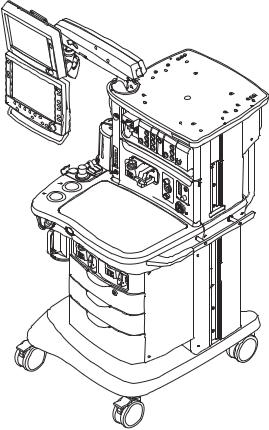
AB.75.097
Figure 1-1 • Aisys Carestation
M1046983 04/08 |
1-3 |
Aisys
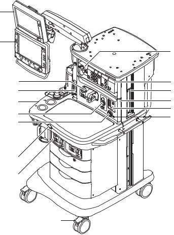
1.4 Anesthesia system components
16
15
14
13
12
11
10
9 |
AB.75.097 |
|
|
8 |
|
7
1.Airway module (optional)
2.Datex-Ohmeda patient monitoring modules (optional)
3.Dovetail rails
4.Light switch
5.Alternate O2 control
6.Mains indicator
7.Brake
8.Aladin cassette storage bay
9.O2 flush button
10.System switch
11.Integrated suction (optional)
12.Advanced breathing system
13.Auxiliary O2 flow control (optional)
14.Aladin cassette and bay
15.Anesthesia display
16.Datex-Ohmeda patient monitoring display (optional)
Figure 1-2 • Front view
1
2
3
4
5
6
1-4 |
04/08 M1046983 |
1 Introduction
11
10
9
1
2
3
4
 5 6
5 6
AB.75.046
7
8
1.Display Unit system interface connections (refer to Section 2.5.1)
2.Collection bottle connection (optional)
3.Cylinder wrench (key) storage
4.Cylinder yoke
5.AGSS (Anesthesia Gas Scavenging System)
6.Pipeline connections
7.Mains inlet
8.System circuit breaker
9.Equipotential stud
10.Isolated electrical outlet
11.Auxiliary connector board
Figure 1-3 • Rear view
M1046983 04/08 |
1-5 |
Aisys
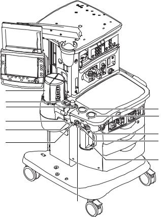
1.5 Breathing system components
 AB.75.098
12
11
10
9
8
7
6
1.Expiratory check valve
2.Inspiratory check valve
3.Inspiratory flow sensor
4.Expiratory flow sensor
5.Absorber canister
6.Absorber canister release
7.Leak test plug
8.Manual bag port
9.Breathing system release
10.Adjustable pressure-limiting (APL) valve
11.Bag/Vent switch
12.Bellows assembly
Figure 1-4 • Advanced breathing system
1
2
3
4
5
1-6 |
04/08 M1046983 |

1.5.1 Optional system components
3 2
1.Bag support arm
2.Auxiliary Common Gas Outlet (ACGO) switch
3.ACGO port
4.EZchange Canister system (CO2 bypass)
5.EZchange Canister release
6.Condenser drain button
7.Condenser
1
|
7 |
AB.75.049 |
AB.82.043 |
6
Figure 1-5 • Breathing system options
1 Introduction
4
5
M1046983 04/08 |
1-7 |
Aisys
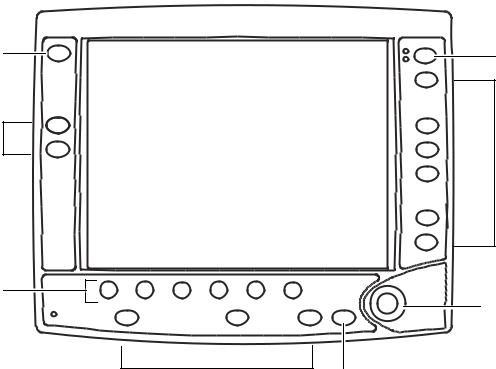
1.6 Display controls
7
6
5
1
2
AB.75.099
3
2 |
4 |
1. |
Alarm Silence key |
Push to silence any active, silenceable high and medium priority alarms or |
|
|
to suspend/acknowledge any non-active medium or high priority alarms. |
|
|
Alarm is silenced for 120 seconds or alarm is suspended for 90 seconds. |
2. |
Menu keys |
Push to show corresponding menu. |
3. |
ComWheel |
Push to select a menu item or confirm a setting. Turn clockwise or |
|
|
counterclockwise to scroll menu items or change settings. |
4. |
Normal Screen key |
Push to remove all menus from the screen. |
5. |
Quick keys |
Push to change corresponding gas setting or ventilator setting. Turn the |
|
|
ComWheel to make a change. Push the ComWheel to activate the change. |
6. |
Timer keys |
Push to start or stop the timer. Push to reset the timer back to zero. |
7. |
MV/TV Alarms key |
Push to turn off the MV and TV alarms. Push again to turn the MV and TV |
|
|
alarms back on. |
Figure 1-6 • Display controls
1-8 |
04/08 M1046983 |

1 Introduction
1.7 Anesthesia system display
2 |
3 |
4 |
5 |
6 |
|
|
|
|
7 |
1 |
|
|
|
|
|
|
|
|
8 |
|
|
|
|
AB.75.006 |
12 |
11 |
10 |
|
9 |
1.Electronic gas flow indicators
2.Alarm silence countdown
3.Alarm message fields
4.Waveform fields
5.General message field or timer field
6.Clock
7.Battery indicator field
8.Measured values field
9.Pipeline and cylinder supply or respiratory data
10.Ventilator settings
11.Ventilation mode
12.Gas and agent settings
Figure 1-7 • Normal view
M1046983 04/08 |
1-9 |

Aisys
When a menu key is selected, the menu field overlays the gas flow tubes and the waveform fields start at the right edge of the menu.
2
1
AB.75.007
1.Menu
2.Waveform fields
Figure 1-8 • Menu view
1-10 |
04/08 M1046983 |
1 Introduction
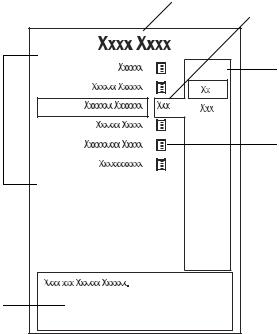
1.7.1 Using menus Push a menu key to display the corresponding menu. Use the ComWheel to navigate through the menu.
|
1 |
|
2 |
|
3 |
6 |
|
|
4 |
|
Xxxxxx Xxxxxx |
5 |
AB.91.007 |
|
1.Menu title
2.Present selection
3.Adjustment window
4.Indicates submenu
5.Short instructions
6.Menu selections
Figure 1-9 • Example menu
1.Push the menu key to display the corresponding menu.
2.Turn the ComWheel counterclockwise to highlight the next menu item. (Turn the ComWheel clockwise to highlight the previous menu item.)
3.Push the ComWheel to enter the adjustment window or a submenu.
4.Turn the ComWheel clockwise or counterclockwise to highlight the desired selection.
5.Push the ComWheel to confirm the selection.
6.Select Normal Screen or push the Normal Screen key to exit the menu and return to the normal monitoring display. (Select Previous Menu to return to the last displayed menu, if available.)
M1046983 04/08 |
1-11 |

Aisys
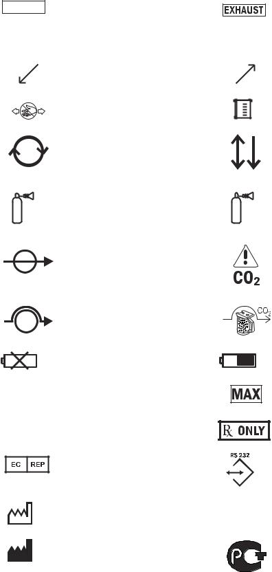
1.8 Symbols used in the manual or on the equipment
Symbols replace words on the equipment, on the display, or in Datex-Ohmeda manuals. No one device or manual uses all of the symbols.
Warnings and Cautions tell you about dangerous conditions that can occur if you do not follow all instructions in this manual:
•Warnings tell about a condition that can cause injury to the operator or the patient.
•Cautions tell about a condition that can cause damage to the equipment.
Read and follow all warnings and cautions.
m |
On (power) |
|
|
L |
Off (power) |
l |
Standby |
n |
Standby or preparatory state for part of |
the equipment |
|
M |
“ON” only for part of the equipment |
N |
“OFF” only for part of the equipment |
† |
Direct current |
p |
Alternating current |
xProtective earth ground
yEarth ground
P |
Frame or chassis ground |
YEquipotential
A
j
J
D w
wW
O
Alarm silence
Alarm silence
Type B equipment
Type BF equipment
Type CF equipment
Caution, ISO 7000-0434
Attention, refer to product instructions, IEC 60601-1
Dangerous voltage
Electrical input
Electrical output
Pneumatic input
Pneumatic output
1-12 |
04/08 M1046983 |

+Plus, positive polarity
-Minus, negative polarity
tVariability
TVariability in steps
o |
Lamp, lighting, illumination |
g |
This way up |
Pipeline
zLock
ZUnlock
U |
Close drain |
|||
u |
Drain (remove condensate) |
|||
Í |
Not autoclavable |
|||
134°C |
Autoclavable |
|||
|
|
|
|
APL settings are approximate |
|
|
|
|
Bellows volumes are approximate |
|
|
|
|
|
|
|
|
|
|
k E
r R
O2+
O2%
1 Introduction
Movement in one direction
Movement in two directions
Read top of float
Read to center of float
Vacuum inlet
Suction bottle outlet
Cylinder
Isolation transformer
Linkage system
Risk of Explosion.
Low pressure leak test
Mechanical ventilation
Bag position/ manual ventilation
O2 Flush button
O2 cell connection
M1046983 04/08 |
1-13 |
Aisys
VACUUM
q
< 345 kPa
REF
SN
Vacuum
Inspiratory flow
Inspiratory flow
Pinch hazard
Circle breathing circuit module
The primary regulator is set to pressure less than 345 kPa (50 psi)
Absorber on
Absorber off (CO2 Bypass active)
No battery/battery failure
Stock Number
Serial Number
Authorized representative in the European Community
Date of Manufactur
Manufacturer
Q
< 414 kPa
AGSS
Exhaust
Expiratory flow
Expiratory flow
Submenu
Bain/Mapleson D breathing circuit module
The primary regulator is set to pressure less than 414 kPa (60 psi)
CO2 Bypass Option
EZchange Canister (CO2 bypass)
Battery in use. Bar indicates amount of battery power remaining.
Maximum
Caution: federal law prohibits dispensing without prescription.
RS-232 connection
Anesthetic Gas Scavenging System
GOST R Russian certification
1-14 |
04/08 M1046983 |
Loading...