


Engstrom
Table of contents
 Loading...
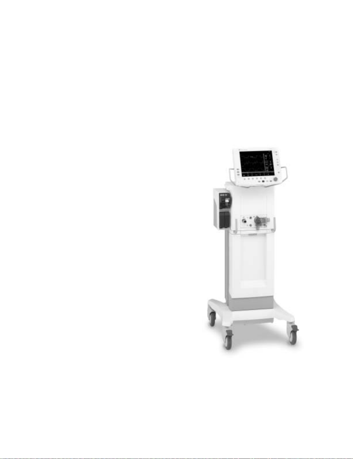
Engström Ventilator
Technical Reference Manual

Engström Ventilator
10/04 1505-1018-000
Datex-Ohmeda products have unit serial numbers with coded logic which indicates a product
group code, the year of manufacture, and a sequential unit number for identification. The serial
number can be in one of two formats.
Engström Ventilator, ComWheel, D-fend
and
EVair 03
are registered trademarks of
Datex-Ohmeda Inc.
Other brand names or product names used in this manual are trademarks or registered
trademarks of their respective holders.
AAA
X
11111 AA A
XX
111111A A
The
X
represents an alpha character
indicating the year the product was
manufactured;
J
= 2004,
K
= 2005, etc.
II
II
and
O
are not used.
The
XX
represents a number indicating
the year the product was manufactured;
04
= 2004,
05
= 2005, etc.

Technical Reference Manual
1505-1018-000 10/04
i
This document is not to be reproduced in any manner, nor are the contents to be disclosed to
anyone, without the express authorization of the product service department, Datex-Ohmeda,
Ohmeda Drive, PO Box 7550, Madison, Wisconsin, 53707.
©
2004 Datex-Ohmeda Inc.
Engström Ventilator

Engström Ventilator
ii
10/04 1505-1018-000
Important
The information contained in this Technical Reference manual pertains only to those models of
products which are marketed by Datex-Ohmeda as of the effective date of this manual or the
latest revision thereof. This Technical Reference manual was prepared for exclusive use by
Datex-Ohmeda service personnel in light of their training and experience as well as the
availability to them of parts, proper tools and test equipment. Consequently, Datex-Ohmeda
provides this Technical Reference manual to its customers purely as a business convenience
and for the customer's general information only without warranty of the results with respect to
any application of such information. Furthermore, because of the wide variety of circumstances
under which maintenance and repair activities may be performed and the unique nature of each
individual's own experience, capacity, and qualifications, the fact that customer has received
such information from Datex-Ohmeda does not imply in anyway that Datex-Ohmeda deems said
individual to be qualified to perform any such maintenance or repair service. Moreover, it should
not be assumed that every acceptable test and safety procedure or method, precaution, tool,
equipment or device is referred to within, or that abnormal or unusual circumstances, may not
warrant or suggest different or additional procedures or requirements.
This manual is subject to periodic review, update and revision. Customers are cautioned to
obtain and consult the latest revision before undertaking any service of the equipment.
Comments and suggestions on this manual are invited from our customers. Send your
comments and suggestions to the Manager of Technical Communications, Datex-Ohmeda,
Ohmeda Drive, PO Box 7550, Madison, Wisconsin 53707.
ww
ww
CAUTION
Servicing of this product in accordance with this
Technical Reference
manual should never
be undertaken in the absence of proper tools, test equipment and the most recent
revision to this service manual which is clearly and thoroughly understood.
Technical Competence
The procedures described in this Technical Reference manual should be performed by trained
and authorized personnel only. Maintenance should only be undertaken by competent
individuals who have a general knowledge of and experience with devices of this nature. No
repairs should ever be undertaken or attempted by anyone not having such qualifications.
Datex-Ohmeda strongly recommends using only genuine replacement parts, manufactured or
sold by Datex-Ohmeda for all repair parts replacements.
Read completely through each step in every procedure before starting the procedure; any
exceptions may result in a failure to properly and safely complete the attempted procedure.

1505-1018-000 10/04 1
Table of Contents
Important . . . . . . . . . . . . . . . . . . . . . . . . . . . . . . . . . . . . . . . . . . . . . . . . . . . . . . . . . . . . . . . . . . . . . .ii
Technical Competence . . . . . . . . . . . . . . . . . . . . . . . . . . . . . . . . . . . . . . . . . . . . . . . . . . . . . . . . . . .ii
1 Introduction
1.1 What this manual includes . . . . . . . . . . . . . . . . . . . . . . . . . . . . . . . . . . . . . . . . . . . . . . . . . .1-2
1.2 User’s Reference manuals . . . . . . . . . . . . . . . . . . . . . . . . . . . . . . . . . . . . . . . . . . . . . . . . . . .1-2
1.2 Conventions used . . . . . . . . . . . . . . . . . . . . . . . . . . . . . . . . . . . . . . . . . . . . . . . . . . . . . . . . . .1-2
1.3 What is an Engström Ventilator? . . . . . . . . . . . . . . . . . . . . . . . . . . . . . . . . . . . . . . . . . . . . . .1-3
1.4 Ventilator overview . . . . . . . . . . . . . . . . . . . . . . . . . . . . . . . . . . . . . . . . . . . . . . . . . . . . . . . . .1-4
1.5 Display controls and indicators . . . . . . . . . . . . . . . . . . . . . . . . . . . . . . . . . . . . . . . . . . . . . . .1-6
1.6 Ventilator display . . . . . . . . . . . . . . . . . . . . . . . . . . . . . . . . . . . . . . . . . . . . . . . . . . . . . . . . . . .1-7
1.6.1 Using menus . . . . . . . . . . . . . . . . . . . . . . . . . . . . . . . . . . . . . . . . . . . . . . . . . . . . . . . .1-9
1.7 Symbols used in the manual or on the equipment . . . . . . . . . . . . . . . . . . . . . . . . . . . . . 1-10

Engström Ventilator
2 10/04 1505-1018-000
2 Theory of Operation
2.1 Pneumatic Operation . . . . . . . . . . . . . . . . . . . . . . . . . . . . . . . . . . . . . . . . . . . . . . . . . . . . . . .2-2
2.1.1 Inspiratory circuit . . . . . . . . . . . . . . . . . . . . . . . . . . . . . . . . . . . . . . . . . . . . . . . . . . . .2-2
2.1.2 Expiratory circuit . . . . . . . . . . . . . . . . . . . . . . . . . . . . . . . . . . . . . . . . . . . . . . . . . . . . .2-7
2.1.3 Associated circuits . . . . . . . . . . . . . . . . . . . . . . . . . . . . . . . . . . . . . . . . . . . . . . . . . . .2-8
2.1.4 Electronic micropump nebulizer . . . . . . . . . . . . . . . . . . . . . . . . . . . . . . . . . . . . . . . .2-8
2.2 Electrical Operation . . . . . . . . . . . . . . . . . . . . . . . . . . . . . . . . . . . . . . . . . . . . . . . . . . . . . . . . .2-9
2.2.1 Display Unit (DU) . . . . . . . . . . . . . . . . . . . . . . . . . . . . . . . . . . . . . . . . . . . . . . . . . . . .2-9
2.2.2 Communication channels . . . . . . . . . . . . . . . . . . . . . . . . . . . . . . . . . . . . . . . . . . . 2-10
2.2.3 Ventilator Control Board - VCB . . . . . . . . . . . . . . . . . . . . . . . . . . . . . . . . . . . . . . . 2-12
2.2.4 Ventilator Monitoring Board - VMB . . . . . . . . . . . . . . . . . . . . . . . . . . . . . . . . . . . . 2-14
2.2.5 Power Management Board – PMB . . . . . . . . . . . . . . . . . . . . . . . . . . . . . . . . . . . . 2-16
2.2.6 Other Electronic Items . . . . . . . . . . . . . . . . . . . . . . . . . . . . . . . . . . . . . . . . . . . . . . 2-16
2.2.7 Motherboard (backplane) . . . . . . . . . . . . . . . . . . . . . . . . . . . . . . . . . . . . . . . . . . . 2-17
2.2.8 Monitoring Interface Board – Monitoring Module Bays . . . . . . . . . . . . . . . . . . . . 2-17
3 Checkout Procedure
3.1 Inspect the system . . . . . . . . . . . . . . . . . . . . . . . . . . . . . . . . . . . . . . . . . . . . . . . . . . . . . . . . .3-2
3.2 Automated Checkout . . . . . . . . . . . . . . . . . . . . . . . . . . . . . . . . . . . . . . . . . . . . . . . . . . . . . . .3-2
3.3 Backlight test . . . . . . . . . . . . . . . . . . . . . . . . . . . . . . . . . . . . . . . . . . . . . . . . . . . . . . . . . . . . . .3-3
3.4 Power failure test . . . . . . . . . . . . . . . . . . . . . . . . . . . . . . . . . . . . . . . . . . . . . . . . . . . . . . . . . . .3-3
3.5 Electrical safety tests . . . . . . . . . . . . . . . . . . . . . . . . . . . . . . . . . . . . . . . . . . . . . . . . . . . . . . .3-3
4 Installation and Service Menus
4.1 Service and Installation menu structure . . . . . . . . . . . . . . . . . . . . . . . . . . . . . . . . . . . . . . . .4-2
4.2 Install/Service Menu (Super User) . . . . . . . . . . . . . . . . . . . . . . . . . . . . . . . . . . . . . . . . . . . . .4-3
4.2.1 Defaults . . . . . . . . . . . . . . . . . . . . . . . . . . . . . . . . . . . . . . . . . . . . . . . . . . . . . . . . . . . .4-4
4.2.2 Factory Defaults . . . . . . . . . . . . . . . . . . . . . . . . . . . . . . . . . . . . . . . . . . . . . . . . . . . . .4-5
4.3 Calibration menu . . . . . . . . . . . . . . . . . . . . . . . . . . . . . . . . . . . . . . . . . . . . . . . . . . . . . . . . . . .4-6
4.4 Service menu . . . . . . . . . . . . . . . . . . . . . . . . . . . . . . . . . . . . . . . . . . . . . . . . . . . . . . . . . . . . . .4-7
4.4.1 Configuration . . . . . . . . . . . . . . . . . . . . . . . . . . . . . . . . . . . . . . . . . . . . . . . . . . . . . . .4-8
4.4.2 Copy Configuration . . . . . . . . . . . . . . . . . . . . . . . . . . . . . . . . . . . . . . . . . . . . . . . . . . .4-9
4.4.3 Service Log menu . . . . . . . . . . . . . . . . . . . . . . . . . . . . . . . . . . . . . . . . . . . . . . . . . . 4-10
4.4.4 Software/Hardware version menu . . . . . . . . . . . . . . . . . . . . . . . . . . . . . . . . . . . . 4-11

Table of Contents
1505-1018-000 10/04 3
5 Service Tests and Calibration
5.1 Calibration (super-user) . . . . . . . . . . . . . . . . . . . . . . . . . . . . . . . . . . . . . . . . . . . . . . . . . . . . .5-2
5.1.1 Calibration procedure . . . . . . . . . . . . . . . . . . . . . . . . . . . . . . . . . . . . . . . . . . . . . . . .5-3
5.2 Service level tests and calibration . . . . . . . . . . . . . . . . . . . . . . . . . . . . . . . . . . . . . . . . . . . . .5-4
5.2.1 Service application setup . . . . . . . . . . . . . . . . . . . . . . . . . . . . . . . . . . . . . . . . . . . . .5-4
5.2.2 Test setup . . . . . . . . . . . . . . . . . . . . . . . . . . . . . . . . . . . . . . . . . . . . . . . . . . . . . . . . . .5-4
5.2.3 Vent engine debris clean-out . . . . . . . . . . . . . . . . . . . . . . . . . . . . . . . . . . . . . . . . . . .5-5
5.2.4 Vent engine leak test (low pressure) . . . . . . . . . . . . . . . . . . . . . . . . . . . . . . . . . . . . .5-6
5.2.5 Vent engine leak test (high O
2
pressure) . . . . . . . . . . . . . . . . . . . . . . . . . . . . . . . . .5-8
5.2.6 Vent engine leak test (high Air pressure) . . . . . . . . . . . . . . . . . . . . . . . . . . . . . . . . 5-10
5.2.7 Calibrate airway pressure transducer Zero and Span . . . . . . . . . . . . . . . . . . . . . 5-12
5.2.8 Verify operation of free- breathing valve . . . . . . . . . . . . . . . . . . . . . . . . . . . . . . . . 5-14
5.2.9 Verify operation of inspiratory effort valve . . . . . . . . . . . . . . . . . . . . . . . . . . . . . . 5-16
5.2.10 Verify operation of auxiliary pressure relief valve . . . . . . . . . . . . . . . . . . . . . . . . 5-18
5.2.11 Mechanical over-pressure valve test . . . . . . . . . . . . . . . . . . . . . . . . . . . . . . . . . 5-20
5.2.12 Verify regulator output pressure. . . . . . . . . . . . . . . . . . . . . . . . . . . . . . . . . . . . . . 5-22
6 Maintenance
6.1 Engström Ventilator planned maintenance . . . . . . . . . . . . . . . . . . . . . . . . . . . . . . . . . . . . . .6-2
6.1.1 Every twelve (12) months . . . . . . . . . . . . . . . . . . . . . . . . . . . . . . . . . . . . . . . . . . . . . .6-2
6.1.2 Every forty-eight (48) months . . . . . . . . . . . . . . . . . . . . . . . . . . . . . . . . . . . . . . . . . .6-2
6.2 Battery capacity test . . . . . . . . . . . . . . . . . . . . . . . . . . . . . . . . . . . . . . . . . . . . . . . . . . . . . . . .6-3
7 Troubleshooting
7.1 Troubleshooting Checkout Failures . . . . . . . . . . . . . . . . . . . . . . . . . . . . . . . . . . . . . . . . . . . .7-2
7.1.1 Paw Transducer Check . . . . . . . . . . . . . . . . . . . . . . . . . . . . . . . . . . . . . . . . . . . . . . . .7-2
7.1.2 Barometric pressure test . . . . . . . . . . . . . . . . . . . . . . . . . . . . . . . . . . . . . . . . . . . . . .7-2
7.1.3 Low Pressure Leak and Compliance Check . . . . . . . . . . . . . . . . . . . . . . . . . . . . . . .7-3
7.1.4 Safety Valve Relief and Back Pressure . . . . . . . . . . . . . . . . . . . . . . . . . . . . . . . . . . .7-3
7.1.5 Exhalation Valve Calibration Check . . . . . . . . . . . . . . . . . . . . . . . . . . . . . . . . . . . . . .7-4
7.1.6 Exhalation Flow Sensor Calibration Test . . . . . . . . . . . . . . . . . . . . . . . . . . . . . . . . . .7-4
7.1.7 Measure Breathing Circuit Resistance . . . . . . . . . . . . . . . . . . . . . . . . . . . . . . . . . . .7-4
7.1.8 Air Inspiratory Flow Sensor Calibration Check . . . . . . . . . . . . . . . . . . . . . . . . . . . . .7-5
7.1.9 O
2
Inspiratory Flow Sensor Calibration Check . . . . . . . . . . . . . . . . . . . . . . . . . . . . .7-5
7.1.10 O
2
Sensor Test and Calibration . . . . . . . . . . . . . . . . . . . . . . . . . . . . . . . . . . . . . . . .7-5
7.2 Troubleshooting Vent Engine Leaks . . . . . . . . . . . . . . . . . . . . . . . . . . . . . . . . . . . . . . . . . . . .7-6
7.3 Alarm message troubleshooting chart . . . . . . . . . . . . . . . . . . . . . . . . . . . . . . . . . . . . . . . . 7-10
7.4 Troubleshooting Service App messages . . . . . . . . . . . . . . . . . . . . . . . . . . . . . . . . . . . . . . 7-26

Engström Ventilator
4 10/04 1505-1018-000
8 Service Diagnostics and Software Download
8.1 EV Service Application . . . . . . . . . . . . . . . . . . . . . . . . . . . . . . . . . . . . . . . . . . . . . . . . . . . . . .8-2
8.1.1 Main Menu and System Information . . . . . . . . . . . . . . . . . . . . . . . . . . . . . . . . . . . . .8-2
8.1.2 Power Diagnostics . . . . . . . . . . . . . . . . . . . . . . . . . . . . . . . . . . . . . . . . . . . . . . . . . . .8-3
8.1.3 Power Controller Power Diagnostics . . . . . . . . . . . . . . . . . . . . . . . . . . . . . . . . . . . . .8-4
8.1.4 Display Unit Power Diagnostics . . . . . . . . . . . . . . . . . . . . . . . . . . . . . . . . . . . . . . . . .8-6
8.2 Display Diagnostics . . . . . . . . . . . . . . . . . . . . . . . . . . . . . . . . . . . . . . . . . . . . . . . . . . . . . . . . .8-7
8.3 Special Functions . . . . . . . . . . . . . . . . . . . . . . . . . . . . . . . . . . . . . . . . . . . . . . . . . . . . . . . . . .8-8
8.3.1 View Revision Log . . . . . . . . . . . . . . . . . . . . . . . . . . . . . . . . . . . . . . . . . . . . . . . . . . . .8-9
8.3.2 View PC Card Install Log . . . . . . . . . . . . . . . . . . . . . . . . . . . . . . . . . . . . . . . . . . . . . . .8-9
8.4 Software Download . . . . . . . . . . . . . . . . . . . . . . . . . . . . . . . . . . . . . . . . . . . . . . . . . . . . . . . 8-10
8.5 EV Service Application (PC based) . . . . . . . . . . . . . . . . . . . . . . . . . . . . . . . . . . . . . . . . . . . 8-12
8.5.1 Port Setup . . . . . . . . . . . . . . . . . . . . . . . . . . . . . . . . . . . . . . . . . . . . . . . . . . . . . . . . 8-12
8.5.2 Main Menu and System Information . . . . . . . . . . . . . . . . . . . . . . . . . . . . . . . . . . . 8-12
8.6 VCB Diagnostics and Calibration . . . . . . . . . . . . . . . . . . . . . . . . . . . . . . . . . . . . . . . . . . . . 8-13
8.6.1 Sensirion Sensors . . . . . . . . . . . . . . . . . . . . . . . . . . . . . . . . . . . . . . . . . . . . . . . . . . 8-13
8.6.2 VCB Input Signal Latch . . . . . . . . . . . . . . . . . . . . . . . . . . . . . . . . . . . . . . . . . . . . . . 8-14
8.6.3 VCB Channel Configurations . . . . . . . . . . . . . . . . . . . . . . . . . . . . . . . . . . . . . . . . . 8-15
8.6.4 VCB Outputs . . . . . . . . . . . . . . . . . . . . . . . . . . . . . . . . . . . . . . . . . . . . . . . . . . . . . . 8-16
8.6.5 Calibrations and Tests . . . . . . . . . . . . . . . . . . . . . . . . . . . . . . . . . . . . . . . . . . . . . . 8-17
8.7 VMB Diagnostics . . . . . . . . . . . . . . . . . . . . . . . . . . . . . . . . . . . . . . . . . . . . . . . . . . . . . . . . . 8-18
8.7.1 VMB Channel Configurations . . . . . . . . . . . . . . . . . . . . . . . . . . . . . . . . . . . . . . . . . 8-19
8.7.2 VMB Outputs . . . . . . . . . . . . . . . . . . . . . . . . . . . . . . . . . . . . . . . . . . . . . . . . . . . . . 8-20
8.7.3 VMB Data . . . . . . . . . . . . . . . . . . . . . . . . . . . . . . . . . . . . . . . . . . . . . . . . . . . . . . . . 8-20
8.7.4 Baro P Cal . . . . . . . . . . . . . . . . . . . . . . . . . . . . . . . . . . . . . . . . . . . . . . . . . . . . . . . . 8-20
9 Repair Procedures
9.1 Circuit Board Replacement precautions . . . . . . . . . . . . . . . . . . . . . . . . . . . . . . . . . . . . . . . .9-3
9.1.1 Software download . . . . . . . . . . . . . . . . . . . . . . . . . . . . . . . . . . . . . . . . . . . . . . . . . . .9-3
9.1.2 Required calibrations . . . . . . . . . . . . . . . . . . . . . . . . . . . . . . . . . . . . . . . . . . . . . . . . .9-3
9.2 How to bleed gas pressure from the machine . . . . . . . . . . . . . . . . . . . . . . . . . . . . . . . . . . . .9-4
9.3 Accessing chassis components . . . . . . . . . . . . . . . . . . . . . . . . . . . . . . . . . . . . . . . . . . . . . . .9-4
9.3.1 To remove the chassis from the housing . . . . . . . . . . . . . . . . . . . . . . . . . . . . . . . . . .9-5
9.3.2 To remove the Vent Engine from the chassis . . . . . . . . . . . . . . . . . . . . . . . . . . . . . .9-5
9.3.3 To replace chassis mounted components . . . . . . . . . . . . . . . . . . . . . . . . . . . . . . . .9-6
9.3.4 To replace Vent Engine components . . . . . . . . . . . . . . . . . . . . . . . . . . . . . . . . . . . . .9-6

Engström Ventilator
1505-1018-000 10/04 5
9.4 Servicing the Display Unit . . . . . . . . . . . . . . . . . . . . . . . . . . . . . . . . . . . . . . . . . . . . . . . . . . . .9-7
9.4.1 Remove the Display Unit . . . . . . . . . . . . . . . . . . . . . . . . . . . . . . . . . . . . . . . . . . . . . .9-7
9.4.2 Disassemble the Display Unit . . . . . . . . . . . . . . . . . . . . . . . . . . . . . . . . . . . . . . . . . .9-8
9.4.3 To replace the CPU board . . . . . . . . . . . . . . . . . . . . . . . . . . . . . . . . . . . . . . . . . . . . .9-9
9.4.4 To replace the LCD display . . . . . . . . . . . . . . . . . . . . . . . . . . . . . . . . . . . . . . . . . . . 9-10
9.4.5 To replace the backlights . . . . . . . . . . . . . . . . . . . . . . . . . . . . . . . . . . . . . . . . . . . . 9-11
9.4.6 To replace the Inverters . . . . . . . . . . . . . . . . . . . . . . . . . . . . . . . . . . . . . . . . . . . . . 9-12
9.4.7 To replace the front enclosure or components . . . . . . . . . . . . . . . . . . . . . . . . . . . 9-13
9.5 Adjusting the display arm . . . . . . . . . . . . . . . . . . . . . . . . . . . . . . . . . . . . . . . . . . . . . . . . . . 9-15
9.5.1 Adjust upper pivot . . . . . . . . . . . . . . . . . . . . . . . . . . . . . . . . . . . . . . . . . . . . . . . . . 9-15
9.5.2 Adjust lower pivot . . . . . . . . . . . . . . . . . . . . . . . . . . . . . . . . . . . . . . . . . . . . . . . . . . 9-16
9.5.3 Adjust arm bearing . . . . . . . . . . . . . . . . . . . . . . . . . . . . . . . . . . . . . . . . . . . . . . . . . 9-16
9.6 Removing a compressor from the cart . . . . . . . . . . . . . . . . . . . . . . . . . . . . . . . . . . . . . . . . 9-17
10 Illustrated Parts
10.1 Service tools . . . . . . . . . . . . . . . . . . . . . . . . . . . . . . . . . . . . . . . . . . . . . . . . . . . . . . . . . . . 10-2
10.1.1 Software tools . . . . . . . . . . . . . . . . . . . . . . . . . . . . . . . . . . . . . . . . . . . . . . . . . . . . 10-2
10.1.2 Manual shut-off valves . . . . . . . . . . . . . . . . . . . . . . . . . . . . . . . . . . . . . . . . . . . . . 10-3
10.1.3 Special tools . . . . . . . . . . . . . . . . . . . . . . . . . . . . . . . . . . . . . . . . . . . . . . . . . . . . . 10-3
10.1.4 Leak test devices. . . . . . . . . . . . . . . . . . . . . . . . . . . . . . . . . . . . . . . . . . . . . . . . . . 10-4
10.1.5 Lubricants and Adhesives . . . . . . . . . . . . . . . . . . . . . . . . . . . . . . . . . . . . . . . . . . 10-5
10.2 External components - front view . . . . . . . . . . . . . . . . . . . . . . . . . . . . . . . . . . . . . . . . . . . 10-6
10.3 External components - rear view . . . . . . . . . . . . . . . . . . . . . . . . . . . . . . . . . . . . . . . . . . . 10-7
10.4 Display arm mounting hardware . . . . . . . . . . . . . . . . . . . . . . . . . . . . . . . . . . . . . . . . . . . 10-8
10.5 Display arm assembly . . . . . . . . . . . . . . . . . . . . . . . . . . . . . . . . . . . . . . . . . . . . . . . . . . 10-10
10.6 Display Unit . . . . . . . . . . . . . . . . . . . . . . . . . . . . . . . . . . . . . . . . . . . . . . . . . . . . . . . . . . . 10-12
10.7 Main enclosure (external) . . . . . . . . . . . . . . . . . . . . . . . . . . . . . . . . . . . . . . . . . . . . . . . . 10-14
10.8 Main enclosure (internal) . . . . . . . . . . . . . . . . . . . . . . . . . . . . . . . . . . . . . . . . . . . . . . . . 10-16
10.9 Vent Engine . . . . . . . . . . . . . . . . . . . . . . . . . . . . . . . . . . . . . . . . . . . . . . . . . . . . . . . . . . . 10-18
10.10 Outlet manifold . . . . . . . . . . . . . . . . . . . . . . . . . . . . . . . . . . . . . . . . . . . . . . . . . . . . . . . 10-20
10.11 Inlet manifold . . . . . . . . . . . . . . . . . . . . . . . . . . . . . . . . . . . . . . . . . . . . . . . . . . . . . . . . 10-22
10.12 AC power cords . . . . . . . . . . . . . . . . . . . . . . . . . . . . . . . . . . . . . . . . . . . . . . . . . . . . . . . 10-23
10.13 AC Inlet/Outlet Components . . . . . . . . . . . . . . . . . . . . . . . . . . . . . . . . . . . . . . . . . . . . 10-24
10.14 Cart . . . . . . . . . . . . . . . . . . . . . . . . . . . . . . . . . . . . . . . . . . . . . . . . . . . . . . . . . . . . . . . . 10-26
10.15 Module rack . . . . . . . . . . . . . . . . . . . . . . . . . . . . . . . . . . . . . . . . . . . . . . . . . . . . . . . . . 10-28
10.16 Compressor . . . . . . . . . . . . . . . . . . . . . . . . . . . . . . . . . . . . . . . . . . . . . . . . . . . . . . . . . . 10-29
10.16 Exhalation valve assembly . . . . . . . . . . . . . . . . . . . . . . . . . . . . . . . . . . . . . . . . . . . . . . 10-30
Schematics and Diagrams

Notes
6 10/04 1505-1018-000

1505-1018-000 10/04 1-1
1 Introduction
In this section
This section provides a general overview of the Engström Ventilator.
1.1 What this manual includes . . . . . . . . . . . . . . . . . . . . . . . . . . . . . . . . . . . . . . . . . . . . . . . . . . .1-2
1.2 User’s Reference manuals . . . . . . . . . . . . . . . . . . . . . . . . . . . . . . . . . . . . . . . . . . . . . . . . . . .1-2
1.2 Conventions used . . . . . . . . . . . . . . . . . . . . . . . . . . . . . . . . . . . . . . . . . . . . . . . . . . . . . . . . . .1-2
1.3 What is an Engström Ventilator? . . . . . . . . . . . . . . . . . . . . . . . . . . . . . . . . . . . . . . . . . . . . . .1-3
1.4 Ventilator overview . . . . . . . . . . . . . . . . . . . . . . . . . . . . . . . . . . . . . . . . . . . . . . . . . . . . . . . . .1-4
1.5 Display controls and indicators . . . . . . . . . . . . . . . . . . . . . . . . . . . . . . . . . . . . . . . . . . . . . . .1-6
1.6 Ventilator display . . . . . . . . . . . . . . . . . . . . . . . . . . . . . . . . . . . . . . . . . . . . . . . . . . . . . . . . . . .1-7
1.6.1 Using menus . . . . . . . . . . . . . . . . . . . . . . . . . . . . . . . . . . . . . . . . . . . . . . . . . . . . . . . .1-9
1.7 Symbols used in the manual or on the equipment . . . . . . . . . . . . . . . . . . . . . . . . . . . . . . 1-10

Engström Ventilator
1-2 10/04 1505-1018-000
1.1 What this manual includes
This manual covers the service information for the Engström Ventilator.
It covers the following components:
• Display Unit
• Integral electronics
• Gas delivery components
• Frame component
Other equipment
Other equipment may be attached to the system. Consult separate
documentation relative to these items for details.
1.2 User’s Reference manuals
Some sections of this manual refer you to the User’s Reference manual for the
Engström Ventilator. To expedite repairs, you must have, and be familiar with,
the User’s Reference manual for this product.
Refer to the Engström Ventilator User’s Reference manual if you need further
information about the operation of the system.
Conventions used
Hard keys
Names of the hard keys on the display and modules are written in bold
typeface, for example,
Normal Screen
.
Menu selections
Menu selections are written in bold italic typeface, for example,
Patient
Setup
.
Messages
Messages that are displayed on the screen are enclosed in single quotes, for
example, ‘Check sample gas out.’
Sections and headings
When referring to different sections or headings in the User’s Reference
manual, the name is written in italic typeface and is enclosed in double
quotes, for example,
“System Controls and Menus.”

1 Introduction
1505-1018-000 10/04 1-3
1.3 What is an Engström Ventilator?
The Engström Ventilator (EV) is a flexible, adaptable, and intuitive critical care
ventilator. A wide selection of performance options gives the user full control
of the system configuration.
The EV must only be operated by authorized medical personnel well trained in
the use of this product, for patient ventilation in the intensive care
environment. It must be operated according to the instructions in this User’s
Reference manual.
The ventilator is designed to be used with infant through adult patients with a
body weight of 5 kg or greater. The EV is designed to maintain lung ventilation
in the absence of spontaneous breathing effort as well as in support of the
patient’s existing spontaneous breathing effort.
The system is designed for facility use, including within-facility transport.
The ventilator consists of three main components: a display, a ventilator unit,
and an optional module bay. The display allows the user to interface with the
system and control settings. The ventilator unit controls electrical power,
nebulization, and pneumatic gas flow to and from the patient. The module bay
allows the integration of various patient monitoring modules with the
ventilator.
Optional accessories include an air compressor, airway modules, module
bay, humidifier and water trap mounting brackets, and auxiliary electrical
outlets.
Figure 1-1 • Engström Ventilator (EV)

Engström Ventilator
1-4 10/04 1505-1018-000
1.4 Ventilator overview
1. Module bay (optional)
2. Ventilator lock [locks Ventilator unit (item 6) to Cart (item 3)]
3. Cart
4. Caster
5. Dovetail rails
6. Ventilator unit
7. Display
8. Nebulizer connection
9. Exhalation valve housing
10. Expiratory inlet
11. Expiratory flow sensor
12. Gas exhaust port
13. Leak test plug
14. Exhalation valve housing latch
15. Water trap
16. Auxiliary pressure port
17. Inspiratory outlet
Figure 1-2 • Front view of the EV
1
2
3
4
5
6
AB.98.007
AB.98.011
891011
13
1415
12
1617
7
1 Introduction
1505-1018-000 10/04 1-5
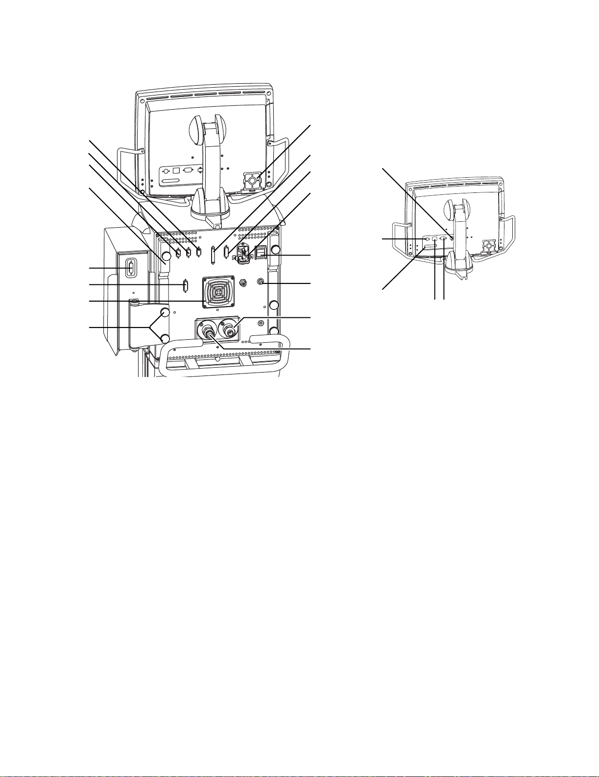
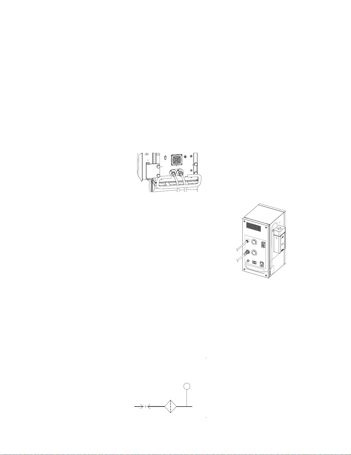
1. Display fan filter
2. Display connection
3. Module bay connection
4. AC mains inlet
5. System switch
6. Equipotential connector
7. Oxygen supply connection (pipeline)
8. Air supply connection (pipeline or compressor)
9. Module bay mounting thumbscrews
10. Ventilator unit fan filter
11. Serial communication port (RS 232 port)
12. Arm holder
13. RS 485 port (not currently supported)
14. RS 485 port (not currently supported)
15. RS 422 port (used to communicate with PC based Service Application — Refer to Section 8.5)
16. Network ID connection
17. Ethernet connection
18. DIS port (not currently supported)
19. USB port
Figure 1-3 • Back view of the E V
2
3
4
5
6
8
10
11
3
AB.98.009
9
7
1
12
13
14
15
18
1617
2
AB.98.045
19

Engström Ventilator
1-6 10/04 1505-1018-000
1.5 Display controls and indicators
Figure 1-4 • Controls and indicators
2
4
3
5
3
AB.98.012
3
7
8
1
6
1 Alarm LEDs The red and yellow LEDs indicate the priority of active alarms.
2 Alarm Silence key Push to silence any active, silenceable high and medium priority alarms or
to suspend any non-active medium priority alarms. Alarm audio is silenced
or suspended for 120 seconds. Push to clear resolved alarms.
3 Menu keys Push to show corresponding menu.
4 ComWheel Push to select a menu item or confirm a setting. Turn clockwise or
counterclockwise to scroll menu items or change settings.
5 Normal Screen key Push to remove all menus from the screen.
6AC mains indicator The green LED lights continuously when the EV is connected to an AC mains
source. The internal batteries are charging when the LED is lit.
7 Quick keys Push to change corresponding ventilator setting. Turn the ComWheel to
make a change. Push the Quick key or ComWheel to activate the change.
8100% O2 key Push to deliver 100% O
2
for 2 minutes.
1 Introduction
1505-1018-000 10/04 1-7
1.6 Ventilator display
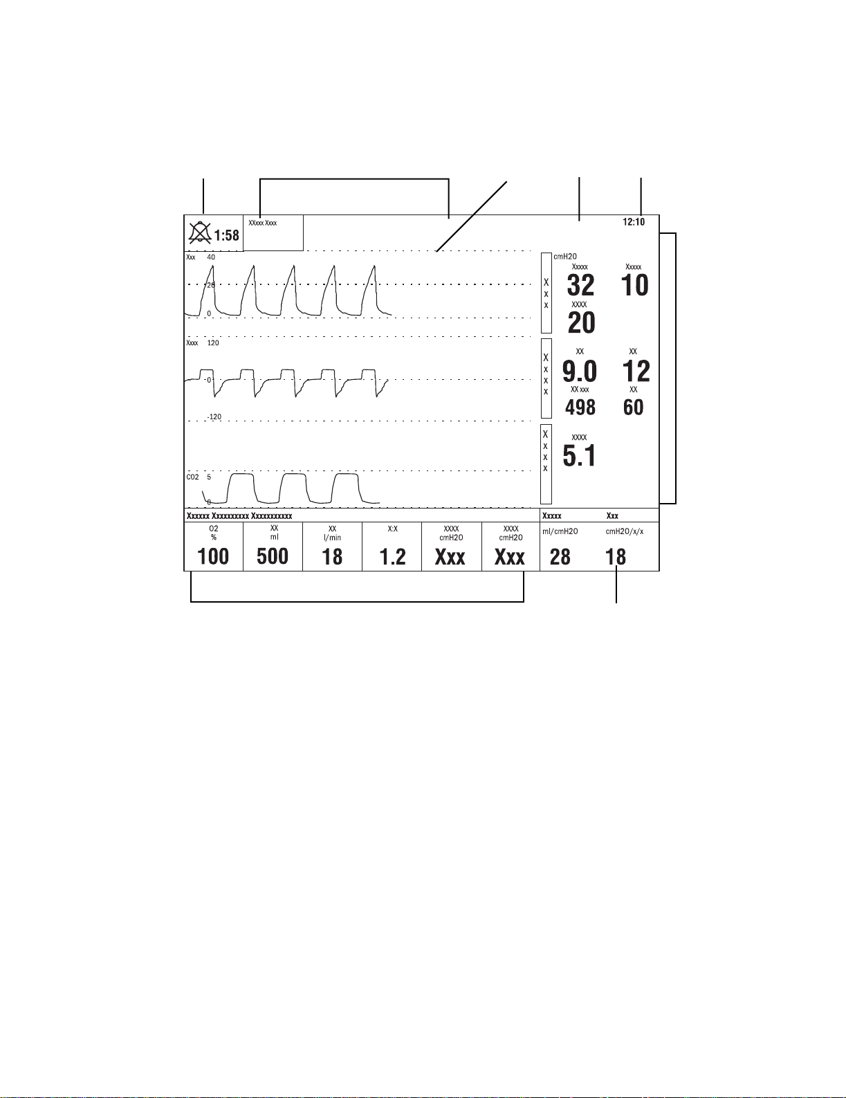
Figure 1-5 • Normal Screen view
12 34
6
7
8
AB.98.013
5
•
1 Alarm silence symbol
and countdown
Displays the time remaining during an alarm silence or alarm suspend period.
2 Alarm message fields Alarms will appear in order of priority. Refer to
“Alarms and Troubleshooting”
for more information
on alarm behavior.
3Waveform fields The top two waveforms are permanently set to Paw and Flow. The third waveform may be selected
as CO
2
, O
2
, Vol, Paux, or Off.
4 General message field Displays informational messages.
5 Clock The time may be set in 12 or 24 hour format in the Time and Date menu.
6 Measured value fields Displays current measured values corresponding to the waveforms.
7 Digit field Displays information related to Volume, CO
2
, O
2
, Compliance or Spirometry.
8Ventilator settings Displays several of the settings for the current mode of ventilation.
Engström Ventilator
1-8 10/04 1505-1018-000
When a menu key is selected the waveform fields start at the right edge of the
menu. The entire waveform is always displayed.
1. Menu
2. Waveform fields
Figure 1-6 • Menu view
1
2
AB.98.014

1 Introduction
1505-1018-000 10/04 1-9
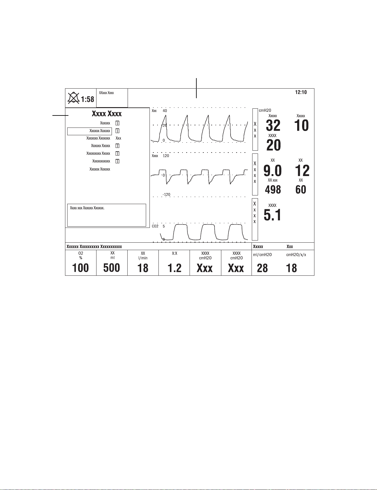
1.6.1 Using menus
Push a menu key to display the corresponding menu. Use the ComWheel to
navigate through the menu.
1. Menu title
2. Present selection
3. Adjustment window
4. Indicates submenu
5. Short instructions
6. Menu selections
Figure 1-7 • Example menu
1. Push the menu key to display the corresponding menu.
2. Turn the ComWheel counterclockwise to highlight the next menu item.
(Turn the ComWheel clockwise to highlight the previous menu item.)
3. Push the ComWheel to enter the adjustment window or a submenu.
4. Turn the ComWheel clockwise or counterclockwise to highlight the
desired selection.
5. Push the ComWheel to confirm the selection.
6. Select
Normal Screen
or push the
Normal Screen
key to exit the menu
and return to the normal monitoring display. (Select
Previous Menu
to
return to the last displayed menu, if available.)
Xxxxxx Xxxxxx
1
2
3
4
6
5
AB.91.007

Engström Ventilator
1-10 10/04 1505-1018-000
1.7 Symbols used in the manual or on the equipment
Symbols replace words on the equipment, on the display, or in
Datex-Ohmeda manuals.
Warnings and Cautions tell about the dangerous conditions that can occur if
the instructions in the manual are not followed.
Warnings tell about a condition that can cause injury to the operator or the
patient.
Cautions tell about a condition that can cause damage to the equipment.
Read and follow all warnings and cautions.
l
On (power)
O
Off (power)
p
On for part of the equipment
œ
Off for part of the equipment
o
Standby
m
Type B protection against
electrical shock
wW
Attention, refer to product instructions
IEC 60601-1
w
Caution, ISO 7000-0434
REF
Stock number
SN
Serial number
†
Direct current
∏
Alternating current
y
Earth ground
x
Protective earth ground
Y
Equipotential connector Fuse
z
Lock
Z
Unlock
t
Variability
T
Variability in steps
+
Plus, positive polarity
-
Minus, negative polarity
N
Movement in one direction
ˆ
Movement in both directions
This way up Warning, dangerous voltage
N
N

1 Introduction
1505-1018-000 10/04 1-11
Pneumatic inlet Pneumatic outlet
Electrical input Electrical output
Inspiratory port Expiratory port
Electrical testing certification Inspiratory breath identifier
Serial port Module data indicator
Module bay port Electronic micropump nebulizer
Auxiliary pressure port Display signal input/output
No battery/battery failure Battery in use. Bar indicates
amount of battery power
remaining.
Silence alarms Submenu
Hourmeter Drain outlet
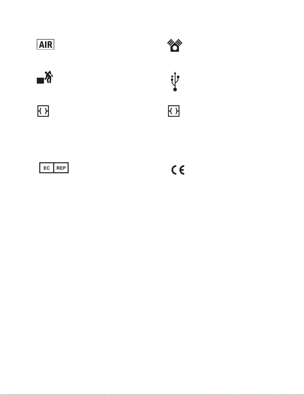
Engström Ventilator
1-12 10/04 1505-1018-000
Air Pump
Heavy object USB port
Ethernet connection Network ID connection
(Datex-Ohmeda proprietary port)
134°C
Autoclavable
Í
Not autoclavable
Authorized representative in the
European Community
Systems with this mark agree with
the European Council Directive
(93/42/EEC) for Medical Devices
when they are used as specified in
their User’s Reference Manuals.
The xxxx is the certification number
of the Notified Body used by
Datex-Ohmeda’s Quality Systems.
ID
X1
XXXX

1505-1018-000 10/04 2-1
2 Theory of Operation
In this section
2.1 Pneumatic Operation . . . . . . . . . . . . . . . . . . . . . . . . . . . . . . . . . . . . . . . . . . . . . . . . . . . . . . .2-2
2.1.1 Inspiratory circuit . . . . . . . . . . . . . . . . . . . . . . . . . . . . . . . . . . . . . . . . . . . . . . . . . . . .2-2
2.1.2 Expiratory circuit . . . . . . . . . . . . . . . . . . . . . . . . . . . . . . . . . . . . . . . . . . . . . . . . . . . . .2-7
2.1.3 Associated circuits . . . . . . . . . . . . . . . . . . . . . . . . . . . . . . . . . . . . . . . . . . . . . . . . . . .2-8
2.1.4 Electronic micropump nebulizer . . . . . . . . . . . . . . . . . . . . . . . . . . . . . . . . . . . . . . . .2-8
2.2 Electrical Operation . . . . . . . . . . . . . . . . . . . . . . . . . . . . . . . . . . . . . . . . . . . . . . . . . . . . . . . . .2-9
2.2.1 Display Unit (DU) . . . . . . . . . . . . . . . . . . . . . . . . . . . . . . . . . . . . . . . . . . . . . . . . . . . .2-9
2.2.2 Communication channels . . . . . . . . . . . . . . . . . . . . . . . . . . . . . . . . . . . . . . . . . . . 2-10
2.2.3 Ventilator Control Board - VCB . . . . . . . . . . . . . . . . . . . . . . . . . . . . . . . . . . . . . . . 2-12
2.2.4 Ventilator Monitoring Board - VMB . . . . . . . . . . . . . . . . . . . . . . . . . . . . . . . . . . . . 2-14
2.2.5 Power Management Board – PMB . . . . . . . . . . . . . . . . . . . . . . . . . . . . . . . . . . . . 2-16
2.2.6 Other Electronic Items . . . . . . . . . . . . . . . . . . . . . . . . . . . . . . . . . . . . . . . . . . . . . . 2-16
2.2.7 Motherboard (backplane) . . . . . . . . . . . . . . . . . . . . . . . . . . . . . . . . . . . . . . . . . . . 2-17
2.2.8 Monitoring Interface Board – Monitoring Module Bays . . . . . . . . . . . . . . . . . . . . 2-17
Engström Ventilator
2-2 10/04 1505-1018-000
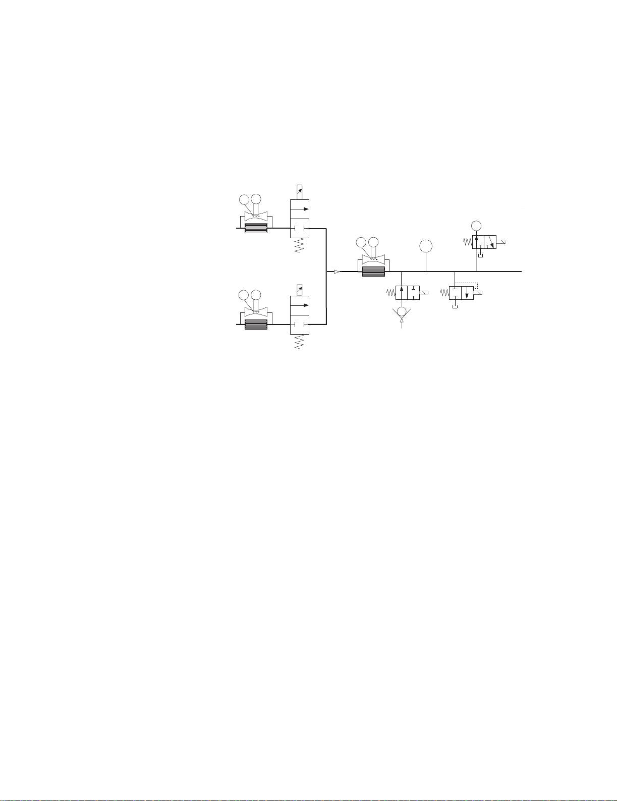
2.1 Pneumatic Operation
For a complete diagram of the pneumatic system, refer to Figure 11-2, "
Vent
Engine manifold flow diagram
" in Section11.
The EV requires a medical-grade oxygen (O
2
) and Air source ranging from 2.4
to 6.5 bar (35 to 94 psi).
The system includes two separate channels (O
2
and Air) to provide dynamic
mixture control of the delivered O
2
percentage.
The Air supply may include an optional compressor unit {1} for applications
where pipeline Air is not available or to provide a continued Air supply if the
pipeline supply goes down.
2.1.1 Inspiratory circuit
Compressed gas enters the EV through an inlet fitting {2} that is particular to
the institution’s supply system. The gas is filtered through a 2-micron
particulate filter {3} as it enters the ventilator’s “pneumatic engine” manifold.
A high-pressure transducer {4} having a dynamic range of 0 to 8.3 bar
(0 to 120 psi) is tapped at the outlet of the filter. This transducer monitors the
adequacy of the supply pressure. Failures of supply gas, coupling hoses or an
occluded filter are identified by the supply pressure transducer.
O2
Air
Air
{1}
Check
Valve
High Pressure
Transducer
Inlet
Filter
Primary
Inlet
P
{2}
{3}
{4}

2 Theory of Operation
1505-1018-000 10/04 2-3
Next in the downstream path of flow is a check valve {5}. The check valve
prevents backflow from the EV that would possibly contaminate the supply
pressure lines. For example; if the O
2
supply were to be lost, the check valve in
the O
2
channel will prevent Air from moving back into the O
2
supply lines.
Downstream from the check valve is a 172 kPa (25 psi) pressure regulator {6}.
(The regulator is a non-relieving type that does not bleed gas into the
ventilator’s enclosure.) The regulator ensures a constant pressure supply to
the flow valve {8}. The regulated supply is flow rate dependant, which is
compensated for in the flow valve’s on-site calibration.
Between the regulator and the flow valves is the inspiratory flow sensor {7}.
The sensor is a thermal mass-flow type that injects heat into the flow stream
and monitors the associated temperature rise at a downstream location. The
temperature change is dependent on the mass flow of the flow stream and
the specific heat of the gas moving through the sensor. Since the composition
of gas in the sensor is known, a conversion of mass-flow rate to volumetric
flow at ambient conditions can be made using the ambient density of the gas.
The sensor uses a laminar (two channel) flow element to split a portion of the
flow through the sensor past the heat injection and temperature sensing
elements. The sensor is pre-calibrated and includes an electronic PCB that
produces direct digital output of mass flow through an RS-232 interface.
Individual flow sensors measure the volume of gas dispensed from the O
2
and
Air channels during inspiration and expiration. The relative proportion of gas
dispensed from each channel is continuously adjusted to precisely control the
percentage of O
2
delivered to the patient.
Check
Valv e
High Pressure
Transducer
Inlet
Filter
Primary
Inlet
P
{5}
25 psi
172 kPa
Flow
Sensor
H
T
Regulator
Flow
Valv e
Check
Valv e
High Pressure
Transducer
Inlet
Filter
Primary
Inlet
Test
Port
P
{6}
{8}
{7}

Engström Ventilator
2-4 10/04 1505-1018-000
Downstream of the flow sensor is a flow valve {8} that meters flows from
approximately 0.05 l/min (leakage level) to a full flow value of 160 l/min. The
valve is a normally- closed proportional solenoid that is powered by a current
feedback loop. When calibrated on-site, using data from the inspiratory flow
sensor, a precise volumetric flow versus input current profile is developed that
includes both the valve and regulator characteristics.
Following the two individual flow valves is the total flow sensor {10}. This
sensor is the same type as the individual flow sensors and is used to measure
the combined inspiratory flow being dispensed from the system. Using the
known mixture composition along with atmospheric pressure and gas
temperature information, mass-flow data from the sensor is converted to
delivered volumetric flow towards the patient. During calibration, the sensor is
checked against the output of the O
2
and Air flow sensors to ensure proper
operation.
25 psi
172 kPa
Flow
Sensor
H
T
Regulator
Flow
Valv e
Check
Valv e
High Pressure
Transducer
Inlet
Filter
Primary
Inlet
Test
Port
P
{8}
Flow
Sensor
Flow
Sensor
Tot al Flow
Inspiratory
Effort
Valv e
Free Breathing
Check Valve
H
T
H
T
Pneumatic
Resistor
Flow
Valv e
Flow
Valv e
H
T
{10}
O
2
Air

2 Theory of Operation
1505-1018-000 10/04 2-5
Following the total flow sensor are the free-breathing check valve {11} and the
inspiratory effort valve {12}.
During normal operation, the inspiratory effort valve is open, allowing the
free-breathing check valve to admit flow if the patient draws a significant
amount of inspiratory pressure, causing the airway pressure to become more
negative than -0.5 cm H
2
O. The free-breathing check valve allows the patient
to spontaneously breathe in case of a ventilation delivery failure.
On occasion, to assess the patient’s tolerance to be weaned from the
ventilator, clinicians can determine the amplitude of inspiratory effort that the
patient can create. During this “procedure”, the inspiratory effort valve is
closed, effectively locking out the free breathing valve from the patient circuit.
Next in the flow path is the O
2
sensor {13}. The sensor is used to monitor the
O
2
concentration produced by the combined O
2
and Air flows.
The O
2
sensor uses the paramagnetic principle (oxygen molecules are
attracted in magnetic fields) to measure the oxygen concentration. The sensor
includes two nitrogen-filled glass spheres mounted on a suspension
containing a conductive coil that is located in a non-uniform magnetic field.
When the system is disturbed by an impulse of current, the suspension begins
to oscillate, inducing an EMF into the coil. The oscillation period of the
induced EMF is dependent on the partial pressure of oxygen surrounding the
suspension.
As sample gas fills the sensor, oxygen that is present in the sample is
attracted into the strongest part of the magnetic field. This congregation of O
2
molecules alters the natural oscillation frequency of the suspension.
Calculations based on the difference between the oscillation period for an
oxygen sample and that for nitrogen, and readings from the absolute pressure
transducer, determine the measured O
2
percentage.
O
2
Flow
Sensor
Flow
Sensor
Tot al Flow
Inspiratory
Effort
Valv e
Free Breathing
Check Valve
H
T
H
T
Pneumatic
Resistor
O2 Sensor
Auxil
Flow
Valv e
Flow
Valv e
Expiratory Press
P
H
T
{13}
O
2
Air
{11}
{12}
Engström Ventilator
2-6 10/04 1505-1018-000
As a safety measure, a relief valve {14}, located downstream from the O
2
sensor, can be energized to vent the full flow rate of the inspiratory delivery
side of the system. If an overpressure condition is detected, the valve can be
opened by either of the EV’s two control processors. To provide redundant
safety (independent of the electronic circuits), the valve begins to
mechanically relieve pressure at a nominal 115 cm H
2
O.
The inspiratory airway pressure transducer {15}, along with its associated
zeroing valve, is located just prior to the inspiratory outlet port. This
transducer has a range of –20 to 120 cm H
2
O and serves as one of three
airway pressure measuring devices in the EV.
O
2
Safety
Relief Valve
Flow
Sensor
Flow
Sensor
Tot al Flow
Inspiratory
Effort
Valv e
Free Breathing
Check Valve
H
T
H
T
P
Pneumatic
Resistor
O2 Sensor
Inspiratory Zero
Valv e
Auxiliary Pressure
Inspiratory Pressure
Flow
Valv e
Flow
Valv e
R
e
li
e
f
Exhalatio
n
Valv e
E
xp
i
ra
t
ory
Z
ero
Valv e
Expiratory Pressure
P
H
T
O
2
Air
{14}
{15}

2 Theory of Operation
1505-1018-000 10/04 2-7
2.1.2 Expiratory circuit At the expiratory side of the ventilator, a solenoid powered exhalation valve
{16} controls exhaust from the breathing circuit. The valve contains an
elastomer diaphragm that is held against a rigid seat by a solenoid (voice coil)
driven piston. The valve achieves a balance between the pressure generated
within its 21-mm diameter seat area and the force applied by the piston,
releasing exhalation flow as necessary to maintain balance. The proportional
solenoid controls the exhalation sealing pressure within a range of 0 to 100
cm H
2
O. Software control provides continuous oscillatory movement
(dithering) of the exhalation valve to minimize static friction effects.
Immediately upstream of the exhalation valve is a tap for the expiratory
pressure transducer {17} and its associated zeroing valve. The expiratory
pressure tap is continuously purged with 35 ml/min of air to ensure that
exhaled condensate does not occlude the tap. The air flow is established from
the regulated Air supply using a fixed orifice (pneumatic resistor) {18}.
Downstream of the exhalation valve is the expiratory flow transducer {19}. In
principle, the transducer is similar to a hot-wire anemometer. A wire having a
large “temperature to electrical resistance” relationship is placed in the
flowstream. The wire is kept at a constant temperature using a Wheatstone
bridge circuit. The current necessary to maintain the resistance of the sensor
portion of the bridge is a function of the flow through the sensor.
At the output of the flow sensor is a flapper type check valve {20} that
prevents gas from being drawn in through the expiratory valve and minimizes
patient rebreathing in the event of a ventilator failure.
O
2
Safety
Tot al Flow
Inspiratory
Effort
Valv e
P
22 / 15 mm
Male / Female
Pneumatic
Resistor
O2 Sensor
Inspiratory Zero
Valv e
Inspiratory Pressure
Micropump
Nebulizer
Patient
H
30 mm Male Cone
22 / 15 mm
Male / Female
Exhalation
Valv e
Exhalation
Flow Sensor
Pneumatic
Resistor
Expiratory Zero
Valv e
Expiratory Pressure
EXP
INSP
P
H
T
{16}
Air
{17}
{18}
{19}
{20}
Patient
From
To

Engström Ventilator
2-8 10/04 1505-1018-000
2.1.3 Associated circuits Associated with the inspiratory and expiratory pressure transducers are two
“zeroing” solenoid valves {21} and {22}. These valves are used to disconnect
the pressure transducers from circuit pressure and vent them to atmosphere
during zero bias calibration. This zeroing procedure is conducted routinely
(every 12 hours) under the control of the Vent Engine software.
A third (auxiliary) pressure channel {23} is used to measure additional patient
“airway” pressures at the discretion of the clinician. This port could be used to
measure circuit pressure directly at the airway, laryngeal cuff pressures or
pressures lower in the airway tract. The transducer circuit includes a valve {24}
to provide a 35 ml/min purge flow as required by the particular clinical
application. For example, in measuring airway pressure at the endotracheal
tube the purge would most likely be turned on, but for measuring laryngeal
cuff pressures (closed system) the purge would be turned off. The purge flow
is established from the regulated Air supply using a fixed orifice (pneumatic
resistor) {25}. The relief valve {26} limits pressure in the auxiliary channel to
less than 230 cm H
2
O.
2.1.4 Electronic
micropump nebulizer
The Aeroneb Professional Nebulizer System (Aeroneb Pro) by Aerogen, Inc.
{27} is integrated into the EV. This nebulizer is electrically connected to the EV
and uses proprietary technology to produce a fine-droplet, low-velocity
aerosolized drug delivered into the breathing circuit.
The Aeroneb Pro is designed to operate in-line with standard ventilator
circuits and mechanical ventilators. It operates without changing the patient
ventilator parameters.
Air
O
2
25 psi
172 kPa
25 psi
172 kPa
Safety
Relief Valve
Flow
Sensor
Flow
Sensor
O
2
Tota l Flow
Inspiratory
Effort
Valve
Free Breathing
Check Valve
H
T
H
T
P
22 / 15 mm
Male / Female
Auxiliary Pressure
Purge Valve
Pneumatic
Resistor
O2 Sensor
Inspiratory Zero
Valve
Auxiliary Pressure
Transducer
Inlet
Filter
High Pressure
Transducer
Primary
Inlet
Check
Valve
Regulator
Inspiratory Pressure
Flow
Valve
Regulator
Flow
Valve
Check
Valve
High Pressure
Transducer
Inlet
Filter
Primary
Inlet
Relief
Valve
Test
Port
Test
Port
Micropump
Nebulizer
P
a
tie
n
t
H
30 mm Male Cone
22 / 15 mm
Male / Female
Exhalation
Valve
Exhalation
Flow Sensor
Pneumatic
Resistor
Expiratory Zero
Valve
Expiratory Pressure
EXP
INSP
1/8,3/16, 1/4 inch Stepped Hose Barb
P
P
P
P
H
T
Paux
{21}
{22}
{23}
{24}
{26}
{25}
{27}
Loading...