


 Loading...
Datex-Ohmeda
S/5™ Anesthesia Monitor and
S/5™ Critical Care Monitor
Technical Reference Manual
|
All specifications are subject to change without notice. |
|
Document No. 8002783 - 0 |
|
June 2001 |
Datex-Ohmeda Inc. |
Datex-Ohmeda Division, |
3030 Ohmeda Drive |
Instrumentarium Corp. |
53707-7550 MADISON, WIS |
P.O. Box 900, FIN-00031 |
USA |
DATEX-OHMEDA, FINLAND |
Tel. +1-608-221 1551 Fax +1-608-2229147 |
Tel. +358 10 394 11 Fax +358 9 146 3310 |
www.us.datex-ohmeda.com |
www.datex-ohmeda.com |
|
Instrumentarium Corp. All rights reserved. |
S/5 Anesthesia Monitor
Intended purpose
The Datex-Ohmeda S/5 Anesthesia Monitor with L-ANE01 or L-ANE01A software is intended for multiparameter monitoring with optional patient care documentation.
Indications for use
The Datex-Ohmeda S/5 Anesthesia Monitor with L-ANE01 or L-ANE01A software is indicated for monitoring of hemodynamic (including arrhythmia and ST segment analysis), respiratory, ventilatory, gastrointestinal/regional perfusion and neurophysiological status of all hospital patients.
The software is also indicated for documenting patient care related information.
The S/5 Anesthesia Monitor with L-ANE01 or L-ANE01A software is indicated for use by qualified medical personnel only.
S/5 Critical Care Monitor
Intended purpose
The Datex-Ohmeda S/5 Critical Care Monitor with L-ICU01 or L-ICU01A software is intended for multiparameter patient monitoring. The monitor is indicated for monitoring of hemodynamic (including arrhythmia and ST segment analysis), respiratory, ventilatory, gastrointestinal/regional perfusion and neurophysiological status of all hospital patients. The system is indicated for use by qualified medical personnel only.
Classifications
In accordance with IEC 60601-1
CLASS I EQUIPMENT - the type of protection against electric shock.
TYPE BF or CF equipment. The degree of protection against electric shock is indicated by a symbol on each parameter module.
EQUIPMENT not suitable for use in the presence of a FLAMMABLE ANESTHETIC MIXTURE WITH AIR OR WITH OXYGEN OR NITROUS OXIDE.
CONTINUOUS OPERATION according to the mode of operation.
In accordance with IEC 60529
Degree of protection against the harmful ingress of water as detailed in the IEC 60529: IPX0
In accordance with EU Medical Device Directive
The Datex-Ohmeda S/5 Anesthesia Monitor and S/5 Critical Care Monitor are classified as IIb.
Responsibility of the manufacturer
Datex-Ohmeda Division, Instrumentarium Corp. is responsible for the safety, reliability and performance of the equipment only if:
−assembly, operations, extensions, readjustments, modifications, service and repairs are carried out by personnel authorized by Datex-Ohmeda.
−the electrical installation complies with appropriate requirements.
−the equipment is used in accordance with the User’s Guide.
−the system is serviced, maintained and used in accordance with the Technical Reference Manual.
Trademarks
Datex®, Ohmeda® and other trademarks S/5, Flexima, D-lite, Pedi-lite, D-fend, D-fend+, MemCard, ComWheel, EarSat, FingerSat, FlexSat, PatientO2, Patient Spirometry and Tonometrics are property of Instrumentarium Corp. or its subsidiaries. All other product and company names are property of their respective owners.
Copyright
© Copyright Instrumentarium Corp. All rights reserved. All specifications subject to change without notice.

Master table of contents
Datex-Ohmeda S/5TM Anesthesia Monitor and Critical Care Monitor
Technical Reference Manual, 8002783 Folder #1(2), PART I, General Service Guide
Document |
Updated |
Updated |
Description |
|
|
No. |
|
|
|
|
|
|
|
|
|
|
1 |
8002783 |
|
|
|
Introduction, System description, Installation, Interfacing, Functional check, General troubleshooting |
|
|
|
|
|
|
2 |
8002949 |
|
|
|
Planned Maintenance Instructions |
|
|
|
|
|
|
|
|
|
|
|
PART II, Product Service Guide |
|
|
|
|
|
|
1 |
8001003 |
- 1 |
|
|
8-Module Frame, F-CU8 |
|
|
|
|
|
|
2 |
8002818 |
|
|
|
CPU Board, B-CPU4 |
|
|
|
|
|
Software Cards, L-ANE01, L-ANE01A, L-ICU01, L-ICU01A |
|
|
|
|
|
|
3 |
8001022 |
- 1 |
|
|
UPINET Board, B-UPI4NET |
|
|
|
|
|
|
4 |
8001004 |
-1 |
|
|
Displays, D-VMC15, D-VHC17, LCD Display, D-LCC15, Display Controllers, B-DISP, B-DVGA |
|
|
|
|
|
|
5 |
8001589 |
-1 |
|
|
Command Bars, K-ANEB, K-ICUB, Remote Controller, K-REMCO |
|
|
|
|
|
|
6 |
8001005 |
- 1 |
|
|
Airway Modules, G-AiOV, G-AiO, G-AOV, G-AO, Gas Interface Board, B-GAS |
|
|
|
|
|
|
7 |
8001006 |
-1 |
|
|
Interface Board, B-INT |
|
|
|
|
|
|
8 |
8001007 |
- 1 |
|
|
Extension Frame, F-EXT4, Extension Module, M-EXT |
|
|
|
|
|
|
9 |
8001020 |
–2 |
|
|
Memory Module, M-MEM |
|
|
|
|
|
|
|
For S/5TM modules see folder #2(2)
Document No. 8002783

S/5™ Anesthesia Monitor and Critical Care Monitor
Document No. 8002783

Master table of contents
Datex-Ohmeda
S/5™ Modules
Technical Reference Manual
Folder #2(2)
Document No. |
Updated |
Updated |
Description |
|
|
|
|
|
|
1 |
|
8001008-2 |
|
|
Hemodynamic Modules, |
||
|
|
|
|
M-NE12STPR, M-NE12STR, M-NE12TPR, M-NESTPR, M-NESTR, M-NETPR, M-ESTPR, M-ESTR, M-ETPR |
|
|
|
|
|
|
2 |
8001009 |
–1 |
|
|
Compact Airway Modules, M-CAiOVX, M-CAiOV,M-CAiO, M-COVX, M-COV, M-CO, M-C |
|
|
|
|
|
|
3 |
8001010 |
-1 |
|
|
Tonometry Module, M-TONO |
|
|
|
|
|
|
4 |
8001011 |
-1 |
|
|
EEG Module, M-EEG and EEG Headbox, N-EEG |
|
|
|
|
|
|
5 |
8001012 |
–1 |
|
|
Cardiac Output Modules, M-COP and M-COPSv |
|
|
|
|
|
|
6 |
8001013 |
–1 |
|
|
Pressure Module, M-P, Pressure Temp Module, M-PT |
|
|
|
|
|
|
7 |
8001014 |
–1 |
|
|
Dual Pressure Module, M-PP |
|
|
|
|
|
|
8 |
8001015 |
–1 |
|
|
NIBP Module, M-NIBP |
|
|
|
|
|
|
9 |
8001016 |
-1 |
|
|
Recorder Module, M-REC |
|
|
|
|
|
|
10 |
8002219 |
|
|
|
Oxygen Saturation Modules, M-NSAT, M-OSAT |
|
|
|
|
|
|
11 |
8001018 |
–1 |
|
|
NeuroMuscular Transmission Module, M-NMT |
|
|
|
|
|
|
12 |
8001019 |
-2 |
|
|
Keyboard for the deioRecorder for Anesthesia, K-ARKB, Keyboard Interface Board, B-ARK |
|
|
|
|
|
and ARK Barcode Reader, N-SCAN |
|
|
|
|
|
|
13 |
8001021 |
- 1 |
|
|
Interface Module, M-INT |
|
|
|
|
|
|
14 |
896616 |
|
|
|
Device Interfacing Solution, N-DISxxxx |
|
|
|
|
|
|
|
For S/5™ Compact Anesthesia Monitor and Compact Critical Care Monitor specific information see 8002782 Folder #1(2),
PART I, General Service Guide and PART II, Product Service Guide
For S/5™ Anesthesia Monitor and Critical Care Monitor specific information see 8002783 Folder #1(2),
PART I, General Service Guide and PART II, Product Service Guide
Document No. 8002782
8002783

S/5™ Compact Anesthesia Monitor and Compact Critical Care Monitor
Document No8002782
8002783

|
|
Table of contents |
TABLE OF CONTENTS |
|
|
S/5™ Anesthesia Monitor and S/5™ Critical Care Monitor |
|
|
TABLE OF CONTENTS |
i |
|
TABLE OF FIGURES |
iv |
|
1 |
INTRODUCTION |
1 |
1.1 |
Notes to the reader ................................................................................................................................... |
2 |
|
1.1.1 Related documentation .................................................................................................................... |
2 |
|
1.1.2 Conventions used............................................................................................................................. |
3 |
1.2 |
Symbols................................................................................................................................................... |
4 |
|
1.2.1 Symbols on transport packaging ....................................................................................................... |
4 |
|
1.2.2 Symbols on equipment..................................................................................................................... |
4 |
1.3 |
Safety ...................................................................................................................................................... |
6 |
|
1.3.1 Classification ................................................................................................................................... |
6 |
|
1.3.2 Responsibility of the manufacturer .................................................................................................... |
7 |
|
1.3.3 Safety precautions ........................................................................................................................... |
7 |
2 |
SYSTEM DESCRIPTION |
10 |
2.1 |
Introduction............................................................................................................................................ |
10 |
2.2 |
Bus structure .......................................................................................................................................... |
10 |
2.3 |
Distributed processing ............................................................................................................................ |
10 |
2.4 |
Module communication .......................................................................................................................... |
11 |
2.5 |
Software loading..................................................................................................................................... |
12 |
2.6 |
Parameter modules ................................................................................................................................ |
12 |
3 |
SYSTEM INSTALLATION |
13 |
3.1 |
Unpacking instructions ........................................................................................................................... |
13 |
3.2 |
Choosing location................................................................................................................................... |
13 |
3.3 |
Central Unit; S/5 8-Module Frame, F-CU8 ............................................................................................... |
13 |
|
3.3.1 Connecting to mains....................................................................................................................... |
14 |
|
3.3.2 Connecting to Datex-Ohmeda Network ............................................................................................ |
14 |
|
3.3.3 Inserting the parameter modules..................................................................................................... |
15 |
|
3.3.4 Positioning of PC boards ................................................................................................................. |
16 |
|
3.3.5 Replacing PC Boards ...................................................................................................................... |
17 |
|
3.3.6 Performing factory reset .................................................................................................................. |
17 |
3.4 |
Displays ................................................................................................................................................. |
18 |
|
3.4.1 Main displays................................................................................................................................. |
18 |
|
3.4.2 Secondary display.......................................................................................................................... |
18 |
|
3.4.3 3rd display...................................................................................................................................... |
18 |
|
3.4.4 S/5 Video Display, D-VMC15.......................................................................................................... |
18 |
|
3.4.5 S/5 LCD Display, D-LCC15............................................................................................................. |
19 |
|
3.4.6 15” Video Display, D-VNC15 .......................................................................................................... |
20 |
|
3.4.7 17” Video Display, D-VHC17, revision 00-01................................................................................... |
21 |
|
3.4.8 17” Video Display, D-VHC17, revision 02 ........................................................................................ |
21 |
|
3.4.9 10” LCD Display, D-LCC10A/W....................................................................................................... |
21 |
|
3.4.10 21" Display Monitor Unit, D-VSC21............................................................................................ |
22 |
3.5 |
Display controller boards ........................................................................................................................ |
22 |
|
|
i |
Document No. 8002783

Datex-Ohmeda S/5 Anesthesia Monitor and S/5 Critical Care Monitor |
|
|
|
3.5.1 Jumper settings.............................................................................................................................. |
22 |
3.6 |
S/5 Remote Controller, K-REMCO ........................................................................................................... |
24 |
3.7 |
S/5 Airway Modules, G-XXXX................................................................................................................... |
24 |
|
3.7.1 Connection to Central Unit.............................................................................................................. |
24 |
|
3.7.2 Sample gas exhaust ....................................................................................................................... |
25 |
|
3.7.3 Returning sample gas to patient circuit............................................................................................ |
25 |
3.8 |
Keyboard for the deioRecorder for Anesthesia, K-ARKB ............................................................................ |
26 |
|
3.8.1 Connection to Central Unit.............................................................................................................. |
26 |
|
3.8.2 Connection to LCD Display, D-LCC10A/W ....................................................................................... |
26 |
3.9 |
ARK Barcode Reader, N-SCAN (optional) ................................................................................................. |
26 |
|
3.9.1 Connection to Central Unit/LCD Display, D-LCC10A/W.................................................................... |
26 |
3.10 S/5 Extension Frame, F-EXT4.............................................................................................................. |
27 |
|
|
3.10.1 Mounting of Extension Frame, F-EXT4.......................................................................................... |
28 |
|
3.10.2 Connection to Central Unit.......................................................................................................... |
28 |
|
3.10.3 Inserting parameter modules...................................................................................................... |
28 |
3.11 Troubleshooting ................................................................................................................................. |
28 |
|
4 |
INTERFACING |
29 |
4.1 |
Interfacing external monitors via UPI Board, B-UPI4 or UPINET Board, B-UPI4NET...................................... |
29 |
|
4.1.1 Interconnection Datex-Ohmeda Monitors ........................................................................................ |
29 |
|
4.1.2 Setting interfacing parameters of Datex-Ohmeda monitors............................................................... |
30 |
|
4.1.3 Setting S/5 Anesthesia Monitor and S/5 Critical Care Monitor interfacing parameters ...................... |
30 |
4.2 |
Interfacing external monitors via Interface Module, M-INT, or Interface Board, B-INT .................................. |
30 |
|
4.2.1 Connecting interface connector cables to Interface Board, B-INT ...................................................... |
31 |
|
4.2.2 Connection to external Datex-Ohmeda monitors .............................................................................. |
32 |
|
4.2.3 Connection to Critikon Dinamap 1846SX, Abbott Oximetrix 3 and Baxter Explorer ............................. |
32 |
|
4.2.4 Connection to Baxter Vigilance........................................................................................................ |
32 |
|
4.2.5 Connection to Nellcor N-100 and N-1000....................................................................................... |
32 |
|
4.2.6 Connection to Nellcor N-200 .......................................................................................................... |
33 |
4.3 |
Interfacing external bedside devices via S/5 Device Interfacing Solutions, N-DISxxx .................................. |
33 |
|
4.3.1 Interfaced devices and parameters ................................................................................................. |
34 |
|
4.3.2 Device Interfacing Solution components ......................................................................................... |
36 |
|
4.3.3 Connections .................................................................................................................................. |
36 |
|
4.3.4 Mounting ....................................................................................................................................... |
36 |
|
4.3.5 Selecting the external device .......................................................................................................... |
38 |
|
4.3.6 Selecting the parameter data source............................................................................................... |
38 |
4.4 |
Interfacing Datex-Ohmeda Anesthesia Delivery Unit ................................................................................. |
38 |
|
4.4.1 Interconnection.............................................................................................................................. |
38 |
|
4.4.2 Setting interfacing parameters on the S/5 Anesthesia Delivery Unit.................................................. |
38 |
|
4.4.3 Setting interfacing parameters on the S/5 Anesthesia Monitor ......................................................... |
39 |
4.5 |
Interfacing Dräger Cicero, Cato, Julian and Narkomed 2C (by NAD) ........................................................... |
40 |
|
4.5.1 Interconnection.............................................................................................................................. |
40 |
|
4.5.2 Setting communication parameters ................................................................................................ |
40 |
|
4.5.3 Setting interfacing parameters on the S/5 Anesthesia Monitor or S/5 Critical Care Monitor ............... |
40 |
4.6 |
Interfacing printer ................................................................................................................................... |
41 |
|
4.6.1 Connection to HP LaserJet 4P printer............................................................................................... |
41 |
|
4.6.2 Connection to Epson EPL-5200 printer............................................................................................ |
41 |
|
4.6.3 Connection to Epson EPL-5500 printer............................................................................................ |
43 |
4.7 |
Interfacing computer .............................................................................................................................. |
44 |
4.8 |
UPI4 and UPI4NET Board Output Signals ................................................................................................. |
44 |
ii |
|
|
Document No. 8002783
|
|
|
Table of contents |
|
|
|
|
|
4.8.1 Digital outputs................................................................................................................................ |
44 |
|
|
4.8.2 Analog outputs............................................................................................................................... |
45 |
|
4.9 S/5 Pressure Temp Module, M-PT, output signals .................................................................................... |
46 |
||
|
4.9.1 Analog outputs............................................................................................................................... |
46 |
|
5 |
FUNCTIONAL CHECK |
47 |
|
5.1 Recommended tools............................................................................................................................... |
47 |
||
5.2 |
Visual inspection .................................................................................................................................... |
48 |
|
5.3 |
Functional inspection.............................................................................................................................. |
48 |
|
|
5.3.1 General.......................................................................................................................................... |
48 |
|
|
5.3.2 Display(s)....................................................................................................................................... |
49 |
|
|
5.3.3 Keyboard(s) ................................................................................................................................... |
49 |
|
|
5.3.4 8-Module Frame, F-CU8 ................................................................................................................. |
49 |
|
|
5.3.5 Extension Frame, F-EXT4................................................................................................................. |
49 |
|
|
5.3.6 Airway Module, G-XXXX ................................................................................................................... |
50 |
|
|
5.3.7 Compact Airway Module ................................................................................................................. |
50 |
|
|
5.3.8 Tonometry Module, M-TONO ........................................................................................................... |
51 |
|
|
5.3.9 Hemodynamic Modules.................................................................................................................. |
51 |
|
|
5.3.10 Pressure/Pressure Temp Modules, M-P/-PT ................................................................................ |
52 |
|
|
5.3.11 Dual pressure Module, M-PP ...................................................................................................... |
52 |
|
|
5.3.12 Cardiac Output Modules, M-COP/-COPSv ................................................................................... |
53 |
|
|
5.3.13 NIBP module, M-NIBP ................................................................................................................ |
53 |
|
|
5.3.14 Nellcor Compatible Saturation module, M-NSAT.......................................................................... |
53 |
|
|
5.3.15 Datex-Ohmeda Oxygen Saturation module, M-OSAT .................................................................... |
53 |
|
|
5.3.16 |
Memory Module, M-MEM ........................................................................................................... |
54 |
|
5.3.17 |
Recorder Module, M-REC............................................................................................................ |
54 |
|
5.3.18 Network Board, B-NET and UPINET board, B-UPI4NET.................................................................. |
54 |
|
|
5.3.19 |
Interface Board/Module, B-INT/M-INT ........................................................................................ |
54 |
|
5.3.20 Device Interfacing Solution, N-DISxxx .......................................................................................... |
54 |
|
|
5.3.21 |
General...................................................................................................................................... |
54 |
6 |
General troubleshooting |
55 |
|
APPENDIX A |
|
57 |
|
Functional Check Form |
A-1 |
||
iii
Document No. 8002783

Datex-Ohmeda S/5 Anesthesia Monitor and S/5 Critical Care Monitor |
|
|
TABLE OF FIGURES |
|
|
Figure 1 S/5 AM with D-VMC15 monitor and S/5 CCM with D-LCC15.................................................................. |
1 |
|
Figure 2 General bus structure of S/5 system ................................................................................................... |
10 |
|
Figure 3 Distributed processing in S/5 system.................................................................................................. |
11 |
|
Figure 4 Principle of UPI board operation.......................................................................................................... |
11 |
|
Figure 5 |
Software loading ................................................................................................................................ |
12 |
Figure 6 General structure of parameter modules.............................................................................................. |
12 |
|
Figure 7 Central Unit; S/5 8-Module Frame, F-CU8........................................................................................... |
13 |
|
Figure 8 Parameter module insertion................................................................................................................ |
15 |
|
Figure 9 Rear view and PC board positioning .................................................................................................... |
16 |
|
Figure 10 |
Service reset button ....................................................................................................................... |
17 |
Figure 11 |
Display options .............................................................................................................................. |
18 |
Figure 12 |
Brightness and contrast controls, D-VNC15..................................................................................... |
20 |
Figure 13 |
Jumper settings, B-DISP rev. 00...................................................................................................... |
22 |
Figure 14 |
Jumper settings, B-DISP rev. 01, or higher....................................................................................... |
23 |
Figure 15 |
AUTO/VGA resolution jumper settings, B-DISP rev. 01, or higher ...................................................... |
23 |
Figure 16 |
Jumper settings B-DVGA board, rev. 01, and B-DHIGH board, rev. 01 (s/n < 174671) ..................... |
23 |
Figure 17 |
Jumper settings, B-DVGA board, rev. 02-03, and B-DHIGH board, rev. 01-02 (s/n > 174670) ......... |
23 |
Figure 18 |
Airway Module, G-XXXX................................................................................................................... |
24 |
Figure 19 |
Exhaust to reservoir tube................................................................................................................. |
25 |
Figure 20 |
Exhaust to scavenging tube............................................................................................................. |
25 |
Figure 21 Barcode Reader connected to Central Unit .......................................................................................... |
26 |
|
Figure 22 Barcode Reader connected to LCD Display.......................................................................................... |
26 |
|
Figure 23 |
N-SCAN Barcode Reader connection directly to the keyboard.......................................................... |
27 |
Figure 24 |
S/5 Extension Frame, F-EXT4.......................................................................................................... |
27 |
Figure 25 Connecting the interface connector cables to Interface Board, B-INT................................................. |
31 |
|
Figure 26 |
Connection cables and LED indicators ............................................................................................ |
36 |
Figure 27 |
An example of interfacing external devices with Device Interfacing Solution ...................................... |
37 |
Figure 28 |
S/5 monitor’s general troubleshooting flowchart ............................................................................. |
55 |
iv
Document No. 8002783

General Service Guide
1 INTRODUCTION
The Datex-Ohmeda S/5 Anesthesia Monitor is a modular multiparameter patient monitor used during anesthesia in operating rooms.
The Datex-Ohmeda S/5 Critical Care Monitor provides a full patient profile throughout the care period.
The modular design provides a flexible system that is easy to upgrade. In addition to parameter changes, the modularity includes an easy upgrade to anesthesia record keeping, monitor networking and interfacing with other external devices.
Figure 1 S/5 AM with D-VMC15 monitor and S/5 CCM with D-LCC15
1
Document No. 8002783

Datex-Ohmeda S/5 Anesthesia Monitor and S/5 Critical Care Monitor
1.1 Notes to the reader
This Technical Reference Manual is intended for service personnel and engineers who will perform service and maintenance procedures on the Datex-Ohmeda S/5 Anesthesia Monitor and the Datex-Ohmeda S/5 Critical Care Monitor.
This Technical Reference Manual is divided into two parts and into two different folders:
•Document number 8002783 is the main document and also order number for the whole printed manual. This manual includes Technical Reference Manual Slots and every slot has own document number.
•Part I gives the reader an overview of the S/5 Anesthesia Monitor and S/5 Critical Care Monitor and all monitor specific components e.g. Central Unit and Video Displays. This part of the manual also contains the information needed to installing, interfacing and troubleshooting monitors. Instructions for service procedures; functional check and planned maintenance are also included. Read the manual through and make sure that you understand the procedures described before installation of the monitor. To avoid risks concerning safety or health, strictly observe the warning indications. If you need any assistance concerning the installation, please do not hesitate to contact your authorized distributor.
•Part II gives detailed descriptions of each component of the S/5 monitors e.g. parameter modules and different boards. Service check for each product is included in these slots.
The manufacturer reserves the right to change product specifications without prior notice. Although the information in this manual is believed to be accurate and reliable, the manufacturer assumes no responsibility for its use.
Datex-Ohmeda assumes no responsibility for the use or reliability of its software in equipment that is not furnished by Datex-Ohmeda.
1.1.1 Related documentation
S/5 Anesthesia Monitor
For more specific information about the clinical aspects and technical background refer to:
S/5 Anesthesia Monitor, User’s Guide
S/5 Anesthesia Monitor, User’s Reference Manual
Circuit diagrams, component layout pictures, etc.: Schematic Diagrams
For more specific information about other devices closely related to the S/5 Anesthesia Monitor refer to:
Central, User’s Reference Manual
S/5 Record Keeping, User’s Reference Manual
S/5 Critical Care Monitor
For more specific information about the clinical aspects and technical background refer to:
S/5 Critical Care Monitor, User’s Guide
S/5 Critical Care Monitor, User’s Reference Manual
2
Document No. 8002783

General Service Guide
Circuit diagrams, component layout pictures, etc.: Schematic Diagrams
For more specific information about other devices closely related to the S/5 Critical Care Monitor refer to:
Central, User’s Reference Manual
CS/3 Arrhythmia Workstation, User’s Reference Manual
1.1.2 Conventions used
|
Throughout this manual, the following conventions are used to distinguish procedures or elements |
|
of text: |
? |
Sign the check form after performing the procedure. |
|
|
Hard Keys |
Hard key names on the Command Board, the Remote Controller, and modules are written in bold |
|
D-O Sans (12 pt) typeface, e.g. ECG. |
Menu Items |
Menu items are written in bold italic, D-O Sans (11 pt) typeface, e.g. ECG Setup. |
‘Messages’ |
Messages displayed on the screen are enclosed in single quotes, e.g. ‘Please wait’. |
Chapters |
When referring to different chapters in the same manual, the chapter name is written in italic |
|
typeface and is enclosed in double quotes, e.g. chapter “Cleaning and Care.” |
Other documents |
|
|
When referring to different documents, the document name is written in italic typeface, e.g. refer to |
|
User’s Reference Manual. |
Hypertext links |
Hypertext links on PDF versions are written in blue color. |
WARNING |
Warnings are written in bold typeface (13 pt), for example: |
WARNING |
The 17” display is wall-mountable only. The display must be mounted at 180 cm |
|
/71 inch or higher level to prevent any liquid from entering the display casing. |
CAUTION |
Cautions are written in the following way (13 pt): |
CAUTION |
The circuit boards contain sensitive integrated circuits that can be damaged by an |
|
electrostatic discharge. Careful handling of the boards is therefore essential. |
3
Document No. 8002783

Datex-Ohmeda S/5 Anesthesia Monitor and S/5 Critical Care Monitor
1.2 Symbols
1.2.1 Symbols on transport packaging
The contents of the transport package are fragile and must be handled with care.
Indicates the correct upright position of the transport package.
The transport package must be kept in a dry environment.
Indicates the temperature limitations within which the transport package should be stored.
1.2.2 Symbols on equipment
This battery contains lead acid, and in the event of disposal must be separated from other waste according to local regulations.
Pb
This battery contains Pb and can be recycled.
Pb
Dangerous voltage.
When using the ARK Barcode Reader, N-SCAN, do not stare into beam. The N-SCAN
Barcode Reader is a Class 2 laser product.
4
Document No. 8002783
General Service Guide
Attention, consult accompanying documents.
When displayed next to an O2 value, indicates that the FiO2 low alarm limit is set below 21 %.
When displayed next to an HR value, indicates that the pacer is set on R or a wide QRS is selected.
On the 15” display, D-VMC15, indicates that the display should be supplied from the Central Unit, F-CU8, or from the mains outlet.
On the 15” display, D-VNC15, indicates that the display must be supplied from the Central Unit, F-CU8, or from the mains outlet via an appropriate additional separating transformer.
On the 15” display, D-LCC15, it indicates that the display must be used only together with the original D-LCC15 power adapter. The display should be supplied from the Central Unit, F-CU8, or from the mains outlet.
On the 17” display, D-VHC17 rev.00-01, indicates that the display must only be supplied from the mains outlet, not from the Central Unit, F-CU8.
On the 17” display, D-VHC17 rev. 02 or higher, indicates that the display should be supplied from the Central Unit, F-CU8, or from the mains outlet via an appropriate additional separating transformer.
On the 21” display, D-VSC21, indicates that the display must only be supplied from the mains outlet via an appropriate additional separating transformer, not from the Central Unit, F-CU8.
On the Interface Module, M-INT, indicates that the connection is for external devices and not for patient cables.
On the Tonometry Module, M-TONO, indicates that use only Tonometrics catheters.
On the rear panel of the Central Unit, F-CU8, indicates the following warnings and cautions:
−Electric shock hazard. Do not open the cover or the back. Refer servicing to qualified personnel.
−For continued protection against fire hazard, replace the fuse only with one of the same type and rating.
−Disconnect the power supply before servicing.
Type BF (IEC-60601-1) protection against electric shock.
Type BF (IEC-60601-1) defibrillator-proof protection against electric shock.
Type CF (IEC-60601-1) protection against electric shock.
Type CF (IEC-60601-1) defibrillator-proof protection against electric shock.
When displayed on the upper left-hand corner of the screen, indicates that the alarms are silenced. When displayed on the menu or in digit fields, indicates that the alarm source has been turned off.
5
Document No. 8002783
Datex-Ohmeda S/5 Anesthesia Monitor and S/5 Critical Care Monitor
Other symbols
Equipotentiality. Monitor can be connected to potential equalization conductor.
|
|
|
Alternating current. |
|
|
|
|
Fuse. |
|
|
|
|
Connector for color display. |
|
|
|
|
Display power supply output. |
|
SN, S/N |
||||
Serial Number. |
||||
|
|
|
Sub menu. Selecting this symbol on a menu opens a new menu. |
|
|
|
|
The monitor is connected to the Datex-Ohmeda Network. |
|
|
|
|
The data card (green) and/or the Menu card (white) is inserted. |
|
Indicates beats are detected.
Respiration rate is measured using impedance respiration measurement.
In this manual indicates the procedure for making selections from the menus.
1.3 Safety
1.3.1 Classification
Classification according to IEC 60601-1
•CLASS 1 equipment according to the type of protection against electrical shock.
•TYPE BF or CF equipment according to the degree of protection against electrical shock is given in the specification for each parameter module.
•Equipment not suitable for use in the presence of flammable anesthetic mixture with air or with oxygen/nitrous oxide.
•Continuous operation according to the mode of operation.
Classification according to IEC 60529
Degree of protection against the harmful ingress of water as detailed in IEC 60529: IPX0.
6
Document No. 8002783

General Service Guide
1.3.2 Responsibility of the manufacturer
Datex-Ohmeda Division, Instrumentarium Corp. is responsible for the safety, reliability and the performance of the software and equipment only if:
•Assembly, operations, extensions, readjustments, modifications, service and repairs are carried out by personnel authorized by Datex-Ohmeda.
•The electrical installation of the monitor room complies with appropriate requirements.
•The system is serviced, maintained and used in accordance with the Technical Reference Manual.
1.3.3Safety precautions
Warnings |
|
WARNING |
A WARNING indicates a situation in which the user or the patient may be in |
|
danger of injury or death. |
Power connection
•Before connecting the power cord to the mains outlet, check that the local voltage and frequency correspond with the rating stated on the device plate on the rear panel of Central Unit, F-CU8, and the Video Display, D-VHC17. See instructions for different displays from section “Displays”.
•Connect the monitor to a three-wire, grounded, hospital grade socket. Do not remove the grounding pin from the power plug.
•Use only an intact power cord. Replace the power cord if it is cracked, frayed, broken or otherwise damaged.
•Do not apply tension to the power cord otherwise the cord may get damaged.
•Do not use extension cords or adapters of any type.
Laser radiation
•When using the ARK Barcode Reader, N-SCAN, do not stare into beam. The N-SCAN is a Class 2 laser product.
External connection
•Do not connect any external devices to the monitor other than those specified by DatexOhmeda.
Fuse replacement
•Replace a fuse only with one of the same type and rating.
Explosion hazard
•Do not use the monitor in the presence of flammable anesthetics.
7
Document No. 8002783

Datex-Ohmeda S/5 Anesthesia Monitor and S/5 Critical Care Monitor
Patient safety
•Do not perform any testing or maintenance on the monitor while it is being used on a patient.
•Use only cables and accessories approved by Datex-Ohmeda. Do not modify them. Other cables and accessories may damage the monitor or interfere with the measurement.
•PACEMAKER PATIENTS: The impedance respiration measurement may cause rate changes in Minute Ventilation Rate Responsive Pacemakers. In this case set the pacemaker rate responsive mode off or turn the monitor impedance respiration measurement off.
Cleaning and service
•Only trained personnel with proper tools and test equipment should perform the tests and repairs described in this manual. Unauthorized service may void the monitor warranty.
•Turn the power off and unplug the power cord before cleaning or service. Completely remove any moisture before reconnecting the power cord to the mains outlet.
•Do not touch any exposed wire or conductive surface while any cover is removed and the monitor is energized. The voltages present can cause injury or death.
•Always perform an electrical safety check and a leakage current test on the monitor after service.
Cautions |
|
CAUTION |
A CAUTION indicates a condition that may lead to equipment damage or |
|
malfunction. |
Installation
•Leave a space behind the monitor to allow proper ventilation.
Before use
•Allow two minutes for warm-up and note any error messages or deviations from normal operation.
•Clean the rear panel fan dust filter once a month or whenever necessary.
•Do not connect a sampling line to the female Patient Spirometry connector while the other end of the sampling line is connected to the D-fend water trap. The pressure in the gas sampling system may cause damage to the PVX unit pressure transducer.
Autoclaving and sterilizing
•Do not autoclave any part of the monitor.
•Do not gas sterilize the modules.
Cleaning and service
•Do not use ammonia, phenol, or acetone based cleaners. These cleaners may damage the monitor surface.
8
Document No. 8002783
General Service Guide
•Do not immerse the monitor in any liquid. Do not allow liquid to enter the monitor or modules.
•Electrostatic discharge through the PC boards may damage the components. Before handling PC boards, wear a static control wrist strap. Handle all PC boards by their nonconductive edges and use anti-static containers when transporting them.
•Do not break or bypass the patient isolation barrier when testing PC boards.
Special components
•Special components are used in these monitors which are vital to assure reliability and safety. Datex-Ohmeda assumes no responsibility for damage if replacement components not approved by Datex-Ohmeda are used.
•A lithium battery on the CPU Board. Dispose of the faulty IC containing the battery
according to local regulations.
Batteries
The battery package in the power supply unit contains lead acid (Pb) which is hazardous to the environment and therefore needs to be disposed of carefully according to local regulations.
To replace the batteries safely, please refer to the instructions in this manual.
•Do not short-circuit the battery terminals, this may produce a very high current, which will damage the battery.
•Do not dispose of the battery into open flame, nor put the battery near fire, as it may explode.
•Do not dismantle the battery. It contains electrolyte, which may damage clothing or cause injury to skin or eyes. If exposed to electrolyte, wash the injured area with plenty of clean water and contact a doctor.
See also section “Displays”.
Storage and transport
Do not store or transport the monitor outside the specified temperature and pressure ranges:
Temperature |
-10... |
+50 °C/14...122 °F |
Ambient pressure |
660... |
1060 hPa/500...800 mmHg/660...1060 mbar |
Humidity |
10... |
90 % non-condensing |
except LCD Display: |
10... |
85 %non-condensing |
except D-VSC21 |
20... |
80 % non-condensing |
Discard
Dispose of any device or parts according to local regulations.
The manufacturer accepts no responsibility for any modifications made to the monitor outside its factory.
9
Document No. 8002783
Datex-Ohmeda S/5 Anesthesia Monitor and S/5 Critical Care Monitor
2 SYSTEM DESCRIPTION
2.1 Introduction
Datex-Ohmeda S/5 monitors build up a freely configurable modular system. The architecture is designed to enable different module combinations so that the user is able to get the desirable parameter and feature set. This modular approach makes it possible to add new features when they are needed.
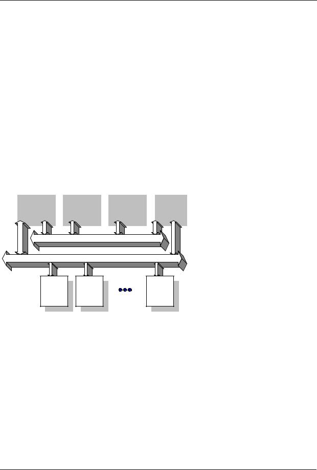
2.2 Bus structure
The operation of Datex-Ohmeda S/5 monitors is based on two communication channels, the CPU bus and the module bus. All boards connected to the CPU bus, as well as the parameter modules attached to the module bus, receive power from the same power supply, which is an integral part of the Central Unit, F-CU8.
UPI |
|
CPU4 |
|
Display |
|
Power |
|
|
|
|
|
Controller |
|
Supply |
|
|
|
|
|
|
|
Unit |
|
|
|
|
|
|
|
|
|
|
CPU Bus |
|
|
Module Bus |
|
Parameter |
Parameter |
Parameter |
Module |
Module |
Module |
The CPU bus is a parallel communication channel used only for internal data transfer between the boards connected to one Central Unit. It is based on the ISA bus used in IBM PC computers. Data is transferred on this 16 bit wide bus using the CPU clock frequency.
The module bus is used to connect the parameter modules to the Central Unit. It based on the widely used industry standard RS-485, which uses a differential serial method to transfer data. This type of bus is robust and it allows parameter modules to be inserted or removed whilst the power is on. The module bus uses a 500 kbps data transfer rate and can be used for longer distances than the CPU bus, e.g. for external frame connections.
Figure 2 |
General bus structure of S/5 system |
The RS-485 type serial communication supports so-called multidrop or party line connections. This means that all parameter modules connected to module bus use the same two wires for communication purposes. The advantage of this is that all module bus connectors are identical and the parameter modules can be connected in any order and position.
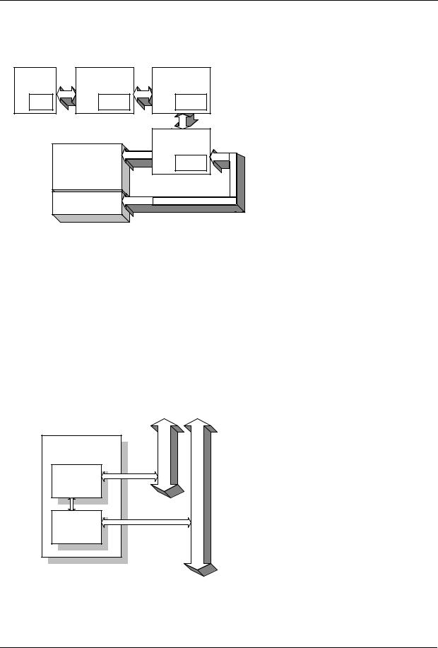
2.3 Distributed processing
A system assembled from S/5 products is a multiprocessor system. All parameter modules have their own microprocessor, which performs low-level functions such as module key control, waveform filtering and pneumatic control, etc. At the same time the main CPU performs higher level tasks such as trending and alarm control. While the parameter modules and CPU are performing their tasks, the UPI (Universal Peripheral Interface) microprocessor handles all functions needed to
10
Document No. 8002783
General Service Guide
transfer data between the parameter modules and the CPU. At the same time the microprocessor on the Display Controller board performs pixel calculations for graphics.
Module UPI
RAM |
Dual-port |
|
RAM |
||
|
Display
Command
Board/Bar
CPU4
System |
memory |
Display
Controller Board
Display |
memory |
This kind of parallel processing gives one major advantage to centralized processing. When new parameter modules or boards are added to the system, the processing power is increased. As a result, the system does not slow down when new features are added.
Figure 3 |
Distributed processing in S/5 system |
2.4 Module communication
The communication master controlling data transfers between the CPU bus and module bus is called the UPI Board. It sends information or questions to each parameter module 100 times per second. If the parameter module is present it replies to each question immediately by sending a data package back to the UPI board; the package length depends on the type of parameter module. This communication protocol ensures that each module receives and sends information every 10 ms. If the parameter module does not respond, the UPI board presumes that the module is not connected.
Each module type has a unique address, which the UPI board uses to send its messages. Two parameter modules of the same type must not be fitted to the same monitor system, otherwise they would both reply at the same time to the same message, resulting in an error.
UPI Board
Dual-port
RAM
Microcontroller
Figure 4
CPU Bus
Module Bus
Principle of UPI board operation
The microcontroller on the UPI board collects and stores all information sent from the parameter modules into a dual-port RAM which is mapped directly to the address space of the main CPU. The main CPU therefore reads information from its own memory whilst the UPI board guarantees that the information is up to date. This operation also works in the other direction. In this direction the main CPU fills the dual-port RAM with data and the UPI board microcontroller distributes it to the parameter modules.
11
Document No. 8002783
Loading...