


S-5
Table of contents
 Loading...
Datex-Ohmeda
Datex-Ohmeda S/5 Central, ViewStation and Network
Technical Reference Manual
0537
Conformity according to the Council Directive 93/42/EEC concerning Medical Devices.
All specifications are subject to change without notice.
CAUTION: U.S. Federal law restricts this device to sale by or on the order of a licensed medical practitioner.
Outside the USA, check local laws for any restriction that may apply.
Document No. 8000633-1
September, 2000
Datex-Ohmeda Inc.
3 Highwood Drive
Tewksbury, MA 01876
Tel. (978) 640-0460 Fax (978) 640-0469
www.us.datex-ohmeda.com
Datex-Ohmeda Division,
Instrumentarium Corp.
P.O. Box 900, FIN-00031
DATEX-OHMEDA, FINLAND
Tel. +358 9 394 11 Fax +358 9 146 3310
www.datex-ohmeda.com
Instrumentarium Corp. All rights reserved.

Datex-Ohmeda S/5 Central, ViewStation and Network
Intended purpose
The Datex-Ohmeda Network transfers information between networked Datex-Ohmeda devices in the Datex-
Ohmeda monitor network. It also allows information transfer between several Centrals. Within one Datex-
Ohmeda monitor network it allows a networked device to display, store, print and otherwise process
information received from other networked devices.
The Datex-Ohmeda S/5 Central maintains the network connections between the Datex-Ohmeda bedside
monitors and other networked devices in Datex-Ohmeda monitor network. Furthermore, it coordinates the
transfer of information between devices in the Datex-Ohmeda Network as well as between the Datex-
Ohmeda Network and Hospital Information Systems (HIS).
The Datex-Ohmeda S/5 Central can be used for storing, printing, viewing or otherwise processing of
information from several bedside monitors or other networked devices.
The Datex-Ohmeda S/5 ViewStation can be used for printing, viewing or otherwise processing of information
from several bedside monitors or other networked devices.
The Datex-Ohmeda Network will be used for patients in the hospital and it is meant for continuous use.
The device is for use by qualified medical personnel only.
CE marking
−
The Datex-Ohmeda S/5 Central software, S-CNET99, and S/5 ViewStation software, S-VNET99, are
CE marked in accordance with the EU Medical Device Directive.
−
The Datex-Ohmeda S/5 Central Patient Screen and Status Screen display units, computer and
keyboard are CE marked in accordance with the EU Directive for Electromagnetic Compatibility of
Low Voltage equipment.
Responsibility of the manufacturer
Datex-Ohmeda Division, Instrumentarium Corp. is responsible for the safety, reliability and performance of
the Datex-Ohmeda manufactured products only if:
−
assembly, operations, extensions, readjustments, modifications, service and repairs are carried out
by personnel authorized by Datex-Ohmeda.
−
electrical installation complies with appropriate requirements.
−
equipment is used in accordance with the User’s Guide and serviced and maintained in accordance
with the Technical Reference Manual.
Storage and Transport
For allowed storage and transport conditions refer to the documentation delivered with the monitor.
Trademarks
Datex®,Ohmeda®, and other trademarks S/5, AS/3, CS/3, D-lite, Pedi-lite, D-fend, D-fend+, MemCard,
ComWheel, EarSat, FingerSat, FlexSat, PatientO
2
, Patient Spirometry and Tonometrics are property of
Instrumentarium Corp. or its subsidiaries. All other product and company names are property of their
respective owners.
All specifications subject to change without notice.
Copyright
Instrumentarium Corp., 1994-2000. All rights reserved.
This manual is protected by copyright. No part of this manual may be electronically copied, photocopied,
reproduced, or translated to another language without the prior written consent of Datex-Ohmeda.

Datex-Ohmeda S/5 Central, ViewStation and Network
i
Document No. 8000633-1
TABLE OF CONTENTS
Datex-Ohmeda S/5 Central, ViewStation and Network
1 Introduction 1
1.1 Symbols ...............................................................................................................................................1
1.2 Abbreviations........................................................................................................................................1
1.2.1 Conventions used in this manual.................................................................................................2
1.3 Safety precautions................................................................................................................................2
2 System description 3
2.1 Datex-Ohmeda Monitor Network............................................................................................................3
2.1.1 Datex-Ohmeda S/5 Central ........................................................................................................4
2.1.2 Monitors ....................................................................................................................................4
2.1.3 Datex-Ohmeda S/5 Arrhythmia Workstation................................................................................5
2.2 Datex-Ohmeda Network (TCP/IP)...........................................................................................................5
2.2.1 ViewStation................................................................................................................................6
2.3 Network services...................................................................................................................................7
2.3.1 Central monitoring and remote viewing of patient sites.................................................................7
2.3.2 Monitor-to-monitor communication.............................................................................................7
2.3.3 Storage for the patient data files and preoperative data files ........................................................8
2.3.4 Storage for the record keeping menu files....................................................................................8
2.3.5 Storage for the user modes.........................................................................................................8
2.3.6 Printing and recording trends and snapshots ...............................................................................8
2.3.7 Access to other hospital data networks........................................................................................9
2.4 Time services ........................................................................................................................................9
2.5 Communication in the network ..............................................................................................................9
2.5.1 Data integrity .............................................................................................................................9
3 Cabling 11
3.1 General ..............................................................................................................................................11
3.1.1 Cabling standards ....................................................................................................................11
3.1.2 General restrictions ..................................................................................................................11
3.1.3 Recommended installation tools...............................................................................................11
3.2 Pre-installation testing ........................................................................................................................11
3.2.1 Site survey ...............................................................................................................................11
3.2.2 Site plan ..................................................................................................................................13
3.2.3 Site planning sheet...................................................................................................................14
3.2.4 Pre-installation test binder........................................................................................................14
3.3 Horizontal cabling ...............................................................................................................................14
3.3.1 Mon/IC-Net cables...................................................................................................................15
3.3.2 Mon-Net cables........................................................................................................................15
3.3.3 Wallboxes ................................................................................................................................16
3.3.4 Horizontal cables......................................................................................................................17
3.3.5 Horizontal patch panels............................................................................................................23
3.3.6 Patch cables ............................................................................................................................24
3.3.7 Hubs........................................................................................................................................25
3.4 Vertical cabling ...................................................................................................................................27
3.5 Cabling examples................................................................................................................................29
3.6 Post-installation testing.......................................................................................................................32

Technical Reference Manual
ii
Document No. 8000633-1
4 Installing Centrals and ViewStations 33
4.1 Components.......................................................................................................................................33
4.2 Unpacking..........................................................................................................................................33
4.3 Placing...............................................................................................................................................34
4.4 Connections .......................................................................................................................................34
5 Configuring 39
5.1 Setup files and tools ...........................................................................................................................39
5.1.1 When to use which setup software? ..........................................................................................39
5.2 Setup Procedure................................................................................................................................. 40
5.2.1 Network setup..........................................................................................................................41
5.2.2 View setup...............................................................................................................................44
5.2.3 System setup...........................................................................................................................46
6 Connecting networks 57
7 Installing a recorder or printer 59
7.1 Installing a recorder ............................................................................................................................59
7.2 Installing a printer...............................................................................................................................59
8 Software Installation 63
8.1 Operating system................................................................................................................................63
8.1.2 Installing the operating system .................................................................................................64
8.1.3 Installing NT Service Pack.........................................................................................................65
8.1.4 Installing driver for the network board........................................................................................65
8.1.5 Installing driver for display controller board ...............................................................................66
8.1.6 Configuring users .....................................................................................................................66
8.2 Installing the network software ............................................................................................................66
9 Functional Check 67
9.1 Checking the equipment and connections............................................................................................67
9.1.1 Checking the Patient Screen.....................................................................................................67
9.1.2 Checking the Status Screen......................................................................................................67
9.1.3 Checking the monitor-to-monitor communication......................................................................67
9.1.4 Checking the communication between the monitor networks .....................................................67
9.1.5 Checking the printer .................................................................................................................67
9.1.6 Checking the recorder ..............................................................................................................68
9.2 Checking the configuration..................................................................................................................68
10 Troubleshooting 81
10.1 Compatibility limitations .....................................................................................................................81
10.2 Network troubleshooting flowchart....................................................................................................... 82
10.3 Central/ViewStation troubleshooting chart...........................................................................................82
10.4 Error messages...................................................................................................................................84
10.5 Technical assistance...........................................................................................................................85
11 Planned maintenance 87
12 Datex-Ohmeda Products 89
12.1 Network Software, S-CNET99 and ViewStation Software S-VNET99.......................................................89
12.1.1Software architecture ...............................................................................................................89
12.1.2Directory Structures..................................................................................................................90
12.2 Start-up Procedure .............................................................................................................................93

Datex-Ohmeda S/5 Central, ViewStation and Network
iii
Document No. 8000633-1
12.2.1After having exited the program.................................................................................................93
12.2.2After having switched off the Network Computer.........................................................................93
12.3 System/Installation menu...................................................................................................................93
12.3.1Alarms setup............................................................................................................................94
12.3.2Recorder setup.........................................................................................................................94
12.4 Service Pages .....................................................................................................................................95
12.4.1Viewing Service Pages ..............................................................................................................95
12.4.2Components page ....................................................................................................................95
12.5 Central Keyboard, K-CENTRALB ........................................................................................................ 103
12.5.1Technical specifications......................................................................................................... 103
12.5.2Functional description ........................................................................................................... 103
12.5.3Keyboard connector .............................................................................................................. 105
12.5.4Service and repair procedures................................................................................................ 105
12.5.5Disassembly and reassembly................................................................................................. 105
12.5.6Functional checkout .............................................................................................................. 110
12.5.7Service and repair procedures................................................................................................ 111
12.5.8Spare parts ........................................................................................................................... 111
12.5.9Exploded view of the keyboard ............................................................................................... 112
12.6 Datex-Ohmeda Display Controller Board, B-CDISP............................................................................. 113
12.6.1Technical Specifications ........................................................................................................ 113
12.6.2Functional description ........................................................................................................... 113
12.6.3Display connector ................................................................................................................. 115
12.6.4Jumper settings..................................................................................................................... 115
12.6.5Replacing the Display Controller Board, B-CDISP.................................................................... 116
12.6.6Service and repair procedures................................................................................................ 117
12.6.7Functional checkout .............................................................................................................. 117
12.7 Spare Parts...................................................................................................................................... 117
13 Other products 119
13.1 Network Computer, C-NTNET............................................................................................................. 119
13.2 Video displays, D-VIC17 and D-VIC15............................................................................................... 119
13.3 Uninterruptible power supply, UPS-500............................................................................................ 119
13.4 Central printer, P-CENTR................................................................................................................... 119
13.5 Strip-chart recorder, N-REC4 ............................................................................................................ 119
13.6 Hubs ............................................................................................................................................... 119

Technical Reference Manual
iv
Document No. 8000633-1
TABLE OF FIGURES
Figure 2-1 Datex-Ohmeda Monitor Network.................................................................................................3
Figure 2-2 Datex-Ohmeda S/5 Central........................................................................................................4
Figure 2-3 Datex-Ohmeda Network (TCP/IP)................................................................................................5
Figure 3-1 Horizontal cabling ....................................................................................................................14
Figure 3-2 Mon/IC-Net Cable....................................................................................................................15
Figure 3-3 Mon-Net cable.........................................................................................................................15
Figure 3-4 Wallbox ...................................................................................................................................16
Figure 3-5 Horizontal cables .....................................................................................................................17
Figure 3-6 Horizontal patch panel .............................................................................................................23
Figure 3-7 Patch cable .............................................................................................................................24
Figure 3-8 Hub.........................................................................................................................................25
Figure 3-9 Vertical cabling ........................................................................................................................27
Figure 3-10 Vertical cables .........................................................................................................................28
Figure 3-11 Cabling example: A simple Datex-Ohmeda Monitor Network.......................................................29
Figure 3-12 Cabling example: A Simple Datex-Ohmeda Network (TCP/IP).....................................................30
Figure 3-13 Cabling example: A more complex Datex-Ohmeda Network (TCP/IP)..........................................31
Figure 3-14 PentaScanner and Super Injector..............................................................................................32
Figure 4-1 Main components of the S/5 Central and ViewStation...............................................................33
Figure 4-2 Typical Connectors on the Network Computer Rear Panel ...........................................................34
Figure 12-1 General architecture of S-CNETxx and S-VNETxx software ...........................................................89
Figure 12-2 Central Keyboard, K-CENTRALB, block diagram...................................................................... 103
Figure 12-3 Keyboard, K-CENTRALB, exploded view.................................................................................. 112
Figure 12-4 Display Controller Board, B-CDISP, general block diagram...................................................... 114
Figure 12-5 Display Controller, B-CDISP, jumper settings.......................................................................... 115
TABLE OF TABLES
Table 3-1 Separations for horizontal cables..............................................................................................18
Table 3-2 Typical fasteners and spacing intervals .....................................................................................19
Table 10-1 General troubleshooting...........................................................................................................82
Table 10-2 Central/ViewStation Troubleshooting........................................................................................82
Table 10-3 Screen messages.....................................................................................................................84
Table 12-1 Keyboard, K-CENTRALB, spare parts ...................................................................................... 111

Datex-Ohmeda S/5 Central, ViewStation and Network
1
Document No. 8000633-1
Part I
1 INTRODUCTION
1.1 Symbols
Attention. Consult accompanying documents.
In this device the symbol means that the device must be supplied from an
appropriate separating transformer when placed in the patient environment.
Fuse. Replace only with a fuse with same type and ratings.
Equipotential terminal.
A LED marked with this symbol indicates recorder error.
Interface device connector.
Page scrolling symbol. The Central and ViewStations are automatically displaying the
next page at configurable intervals.
Alarms silenced from the bedside monitor.
Submenu: there is another menu available under this selection
1.2 Abbreviations
AM Datex-Ohmeda S/5 Anesthesia Monitor
ARK Datex-Ohmeda S/5 Anesthesia Record Keeper
ArrWS Datex-Ohmeda S/5 Arrhythmia Workstation
CCM Datex-Ohmeda S/5 Critical Care Monitor
CM Datex-Ohmeda S/5 Compact Anesthesia Monitor
CMC Datex-Ohmeda S/5 Compact Critical Care Monitor
CRC Cyclic redundancy check
EMI Electromagnetic interference
FTP Foiled twisted pair
HIS Hospital information system
ID Identification
IM Information management
RF Radio frequency
TP Twisted pair
UTP Unshielded twisted pair

Technical Reference Manual
2
Document No. 8000633-1
1.2.1 Conventions used in this manual
To help you find and interpret information easily, the manual uses consistent text formats for
certain text types:
— Command buttons are written in the following way:
Cancel.
— Menu items are written in bold italic typeface, for example Screen 1 Setup.
— Menu access is described from top to bottom. For example, the selection of the Locations
item from the Screen 1 Setup submenu of the Setup menu, would be shown as Setup -
Screen 1 setup - Locations.
— File names, file paths and commands are written in Courier New typeface, for example
comm.exe.
— Messages (alarm messages, informative messages) displayed on the screen are written
inside single quotes, for example ‘Printing...’
— When referring to different sections in this manual, section names are written in italic
typeface and enclosed in double quotes, for example “Cleaning and Care.”
1.3 Safety precautions
WARNING A WARNING indicates that there is a possibility of injury to yourself or others.
• Do not locate the S/5 Central, ViewStation, hubs or printers in a medically used room, they
are non-medical electrical equipment. If locating this type of equipment in this type of room is
necessary, use an appropriate separating transformer.
• Do not connect any other external equipment to the network than those specified by the
manufacturer.
• Switch the Network Computer off before connecting or disconnecting any cables on the rear
panel.
• Check the position of the voltage selector switch on the rear of the Network Computer before
connecting the power cable to the wall socket.
• Connect the devices to a three-wire, grounded, hospital grade receptacle.
• Replace the power cable if it is cracked, broken or otherwise damaged. The cable and the
plug must always be intact and undamaged.
• Do not apply tension to the power cable.
• Do not remove the grounding prong from the power plug.
• Do not use extension cables or adapters of any type.
• Only qualified personnel (distributor, cabling company or technical hospital staff) may carry
out the installation and service.
CAUTION A CAUTION indicates a condition that may lead to equipment damage or
malfunction.
• Do not obstruct the ventilation holes of the Network Computer, displays, nor the hub.
• Prevent accidental disconnection of all cables connected to the S/5 Central.
• Do not immerse any liquid or allow liquid to enter the Network Computer, the device interior.
• Wear a static control wrist strap when handling circuit boards and always hold the boards by
their non-conductive edges.
Datex-Ohmeda S/5 Central, ViewStation and Network
3
Document No. 8000633-1
2 SYSTEM DESCRIPTION
Datex-Ohmeda Monitor Network is an Ethernet based clinical network which is controlled by the
S/5 Central. The S/5 Central provides
− central monitoring and remote viewing of patient sites.
− monitor-to-monitor communication.
− storage for patient data files and preoperative data files, record keeping menu files, and
user modes for the monitors.
− printing of patient data
− recording of waveform snapshots.
− services for sharing printers.
− communication with up to three other Centrals within the Datex-Ohmeda Network (TCP/IP)
− access to other hospital data networks.
− time services.
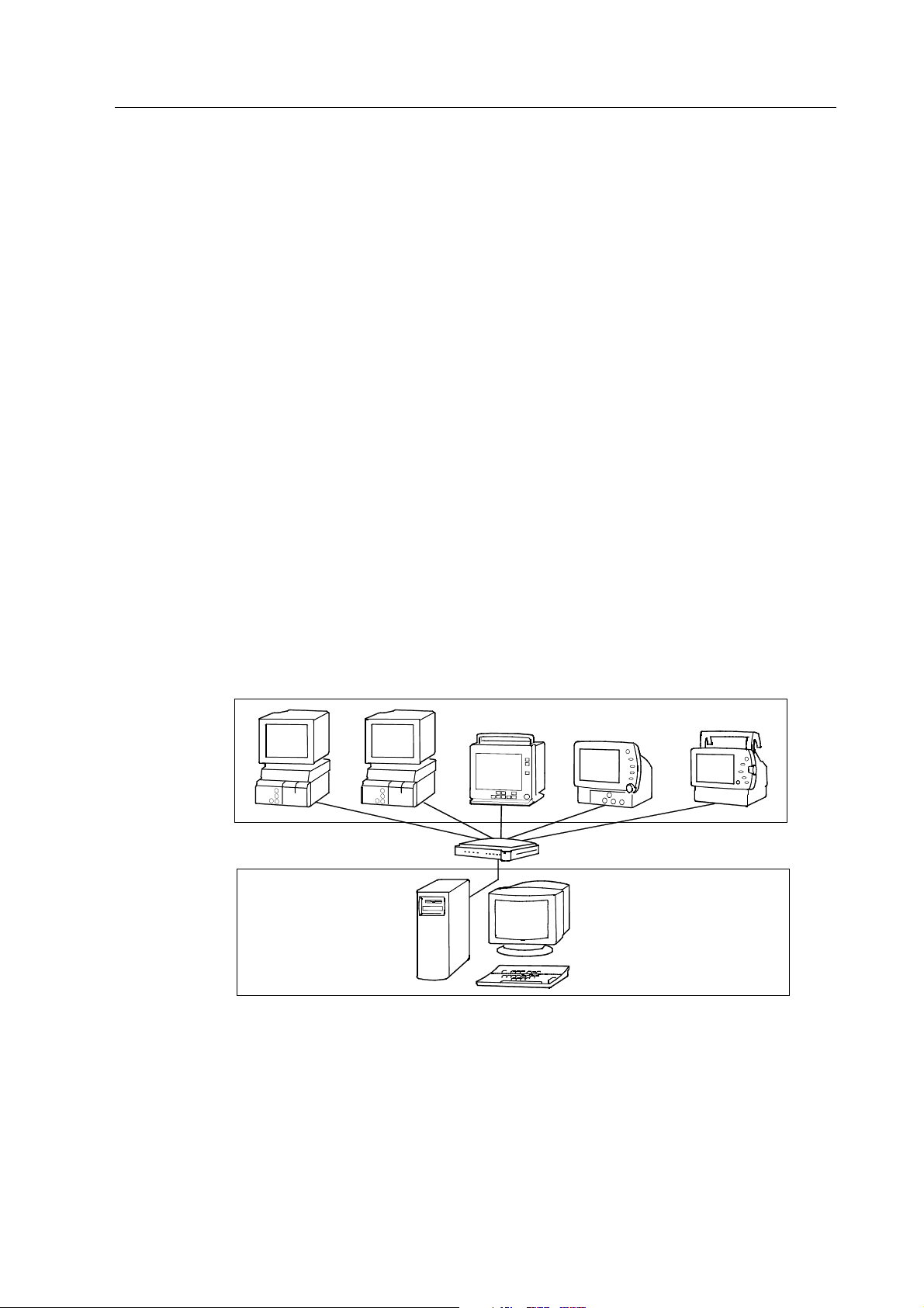
2.1 Datex-Ohmeda Monitor Network
The Datex-Ohmeda monitor network may consist of up to 32 bedside monitors connected via a hub
to the Central.
Figure 2-1 illustrates a typical configuration of the monitor network.
1
2
Figure 2-1 Datex-Ohmeda Monitor Network
(1) Bedside monitors connected to a hub
(2) S/5 Central
The hub (10Base T, 10 Mbps) is a multiport repeater and controls the information flow from all the
monitors to the Central.
Technical Reference Manual
4
Document No. 8000633-1
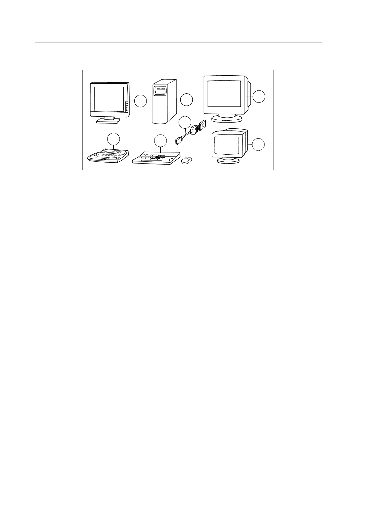
2.1.1 Datex-Ohmeda S/5 Central
1
2
3
4
6
7
5
Figure 2-2 Datex-Ohmeda S/5 Central
(1) Patient Screen (LCD screen)
(2) Network computer + two network boards
(3) Patient screen (CRT screen)
(4) Status Screen
(5) Smart key
(6) PC keyboard and mouse
(7) S/5 Central keyboard
Patient Screen displays patient information such as waveforms, numeric fields, alarms, etc., and
allows access to various system level operations. Patient Screen has built-in loudspeakers. Two
Patient Screens can be connected to a S/5 Central.
Status screen displays system and network information, patient information, alarms and service
pages in text. Status Screen is also used during configuration and when starting and exiting
programs.
The system can be operated either by a PC keyboard and mouse or a specific S/5 Central
keyboard, K-CENTRALB. Only one of the keyboards can be installed at a time. The PC keyboard is
handy during installation and administrational tasks; the S/5 Central keyboard is meant for daily
use of the S/5 Central in patient environment.
Additionally, there can be a strip-chart recorder, N-REC4, or a laser printer connected to the S/5
Central.
2.1.2 Monitors
Which Monitors?
The, monitors which can be connected to the Datex-Ohmeda Monitor Network are:
− Datex-Ohmeda S/5 Anesthesia Monitor, S/5 Compact Anesthesia Monitor, S/5 Critical
Care Monitor and S/5 Compact Critical Care Monitor. These monitors require a network
board, e.g. B-NET or B-UPINET to enable the connection to the network. NOTE: There are
some limitations in data loading capabilities in monitors equipped with S-ANEXX software.
Datex-Ohmeda S/5 Central, ViewStation and Network
5
Document No. 8000633-1
− Datex-Ohmeda Cardiocap/5 with the options N-XNET and N-XDNET
− Datex-Ohmeda S/5 Light Monitor (models F-LM1 and F-LMP1 with options N-LNET and L-
LDNET). NOTE: There are some limitations in the monitor-to-monitor communication and
data loading capabilities in Light Monitor. Please see the Light Monitor’s manuals.
How many monitors?
The number of monitors, (4, 8, 12, …32) connected to the Datex-Ohmeda Monitor Network is set
through the smart key. The smart key is a special plug inserted into the serial port of the S/5
Central. The maximum configuration is 32 monitors.
2.1.3 Datex-Ohmeda S/5 Arrhythmia Workstation
You can connect the Datex-Ohmeda S/5 Arrhythmia Workstation, to the Datex-Ohmeda Monitor
Network. You can connect one monitor to one Arrhythmia Workstation only and 16 monitors to one
workstation at the most. You can connect two Arrhythmia Workstations to a network with 32
monitors.
The Arrhythmia Workstation cannot use the same printer as Central; it requires its own.
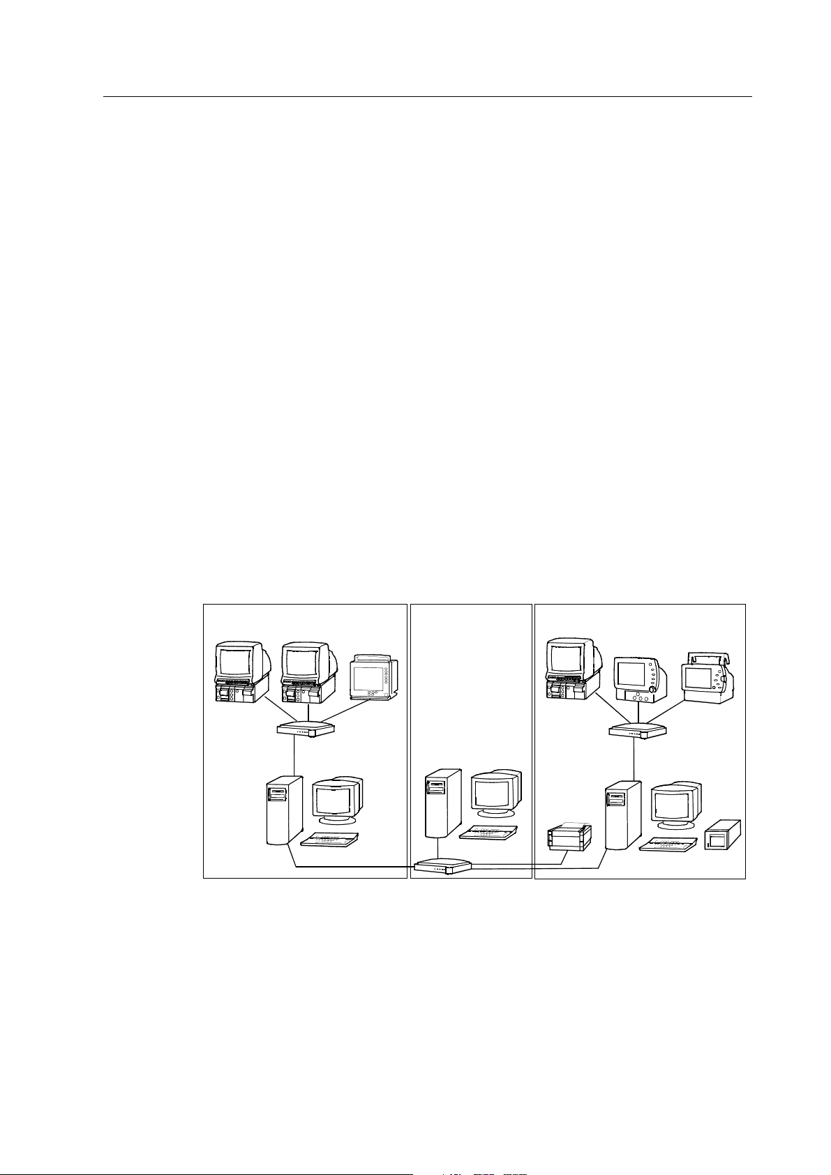
2.2 Datex-Ohmeda Network (TCP/IP)
You can connect up to four Datex-Ohmeda Monitor Networks (4 x 32 monitors) together to form the
Datex-Ohmeda Network (TCP/IP). The network uses the TCP/IP protocol, and the monitor networks
are connected to it via a 100Mbps hub. It is possible to connect up to four S/5 ViewStations to the
Datex-Ohmeda Network (TCP/IP).
3
2
1
Figure 2-3 Datex-Ohmeda Network (TCP/IP)
(1) Monitor network with S/5 Central
(2) Datex-Ohmeda Monitor Network (TCP/IP) with S/5 ViewStation
(3) Monitor network with S/5 Central and a recorder
You can connect a laser printer to the S/5 Central or S/5 ViewStation or directly to the 100 Mbps
hub.

Technical Reference Manual
6
Document No. 8000633-1
2.2.1 ViewStation
Datex-Ohmeda S/5 ViewStation consists of the same components as the Central, and functions
similarly except:
− It runs by the software S-VNETXX.
− There are no monitors connected to it.
− It cannot store patient data.
− It has no smart key (N-ICXX).
− It has only one network board (TCP/IP).
− The ViewStation cannot work without a Central, but the Central works without a ViewStation.
The ViewStation is used for centralized monitoring and remote viewing of patient sites, for example
in the office. A laser printer or recorder can be connected to ViewStation as well.
From a Central you can see only the monitors configured to it but from the ViewStation you can see
any of the monitors connected to the Datex-Ohmeda Network (TCP/IP), up to four monitor
networks. However, you can see a maximum of 32 monitors at a time.
ViewStations are connected to the 100 Mbps hub.
NOTE: To enable connecting ViewStations to the system, the Central requires the software S-
CNET99 Ver 1.2, or newer.

Datex-Ohmeda S/5 Central, ViewStation and Network
7
Document No. 8000633-1
2.3 Network services
The following services are provided by the S/5 Central.
2.3.1 Central monitoring and remote viewing of patient sites
Waveforms, numeric fields, alarms, and other patient information from the networked monitors are
displayed at the Central on the Patient Screen. Real time waveform fields and numeric fields are
transmitted to the Central after start up and the numeric fields are updated every 10 seconds. The
Patient View is a copy of a single bedside monitor's display with a few exceptions, and the Multi
View displays one or two vital waveforms from 8 or 16 beds simultaneously.
Exceptions in Patient View are:
— Split screens are not displayed (minitrends or spirometry loops).
— NMT or EEG data are not displayed.
— In tonometry measurement, the PgCO
2 digit field is displayed only.
— The spirometry loops are not displayed in the digit fields.
— The text messages are not displayed
— No other parameter messages than ‘Apnea’ and arrhythmia messages are displayed in the
corresponding waveform fields, and ‘Audio Off’ and ‘Alarms silenced’ alarm messages are
displayed in the waveform fields.
Alarms are displayed both on the Patient Screen and on the Status Screen. Messages are
transmitted to the Central as the start-up sequence is complete, and then the messages are
transmitted whenever the alarm priority is altered. The priority change at the monitor is displayed at
the Central within two seconds.
2.3.2 Monitor-to-monitor communication
Monitor-to-monitor communication is viewing other monitors at a monitor connected to the
network using either view links or alarm links. Monitor-to-monitor communication is possible both
within the Datex-Ohmeda Monitor Network and the Datex-Ohmeda Network (TCP/IP). In the TCP/IP
network, the monitors must have software level S-XX99 or newer to communicate between
monitors.
The number of simultaneous view links is limited to 16 simultaneously. Alarms, real time waveform
fields, numeric fields and up to 60 minutes of trend data are transmitted. The numerical fields are
updated every 10 seconds and the trend data once a minute.
Number of alarm links is not limited. Alarm messages are transmitted from one monitor to another
via the Central as the alarm is initialized. Afterward the messages are transmitted whenever the
alarm priority has changed.
NOTE: The Datex-Ohmeda S/5 Light Monitor can be connected to the network and viewed from
other monitors, but other monitors cannot be viewed at the Light Monitor.

Technical Reference Manual
8
Document No. 8000633-1
2.3.3 Storage for the patient data files and preoperative data files
You can collect patient data on the hard disk of the Central throughout the case, also during
patient transport, or if the patient is moved to another monitor (data continuum). When the monitor
is not connected to the network, you can save the data on the data card.
Patient data from the networked monitors is stored on the hard disk of the Central. The directory
where the patient data is saved is generated when the patient is admitted or the case is started.
The start time is stored in the status file, and the patient name or identification number is stored in
the identification file. Up to 48 hours of trend data is stored in the trend files, and the record keeper
events are stored in the event file. The end time of the case is added to the status file when the
case is closed or the patient discharged. You can re-open the case within a configured time, max.
24 hours (if there is preoperative data only - no trend data - the time can be extended up to 96
hours).
NOTE: You can load data from the network to the monitors with the software S-ARKXX and S-ICUXX
only and to Cardiocap/5 monitor, not to a monitors with the software S-ANEXX, or Light Monitor.
Trend data from the Light Monitor is not collected to the network, but on a card only.
2.3.4 Storage for the record keeping menu files
The record keeping menu files are stored on the hard disk of the Central during network installation.
You can load the menu pages to the monitors with the software S-ARKXX.
2.3.5 Storage for the user modes
You can use the predefined user modes with the monitors AM, CM, CCM and CMC that define the
monitor setup. You can send the user modes from a monitor to the Central’s hard disk, and load
them to other monitors.
By default, all the monitors with same software type and revision use same user modes. If part of
the monitors needs specific user modes, make a group of the desired monitors, see section 1.
2.3.6 Printing and recording trends and snapshots
Either a laser printer or a strip-chart recorder, N-REC4 can be connected to the S/5 Central. On the
laser printer the S/5 Central can print trends, waveform snapshots, anesthesia records and reports
as defined in the networked monitors. For printer and recorder setup see section “Installing a
recorder” and “Installing a printer.”
Also a network printer can be used, connected directly to the 100 Mbps hub. In that case the
printer must be equipped with a network board (default in the printers sold by Datex-Ohmeda.)
Each monitor can have access to 9 printers at the maximum.
You can start the central printing either from a monitor or the Central. Start the recorder manually
from the recorder or if it is connected to a Central it can be started automatically by an alarm.
Automatic (alarm triggered) printing is not available at the ViewStation.

Datex-Ohmeda S/5 Central, ViewStation and Network
9
Document No. 8000633-1
2.3.7 Access to other hospital data networks
You can convert information from other hospital networks, like admission data and laboratory
results to record keeping events and send them to the monitors, and vice versa. However, you
cannot connect the Datex-Ohmeda Monitor Network or Network (TCP/IP) to the hospital
information system (HIS) directly, but via a Datex-Ohmeda IM server connected to the 100Mbps
hub. For transferring information from the system to another, refer to the S/5 Anesthesia System
Interface and Inlink manual, and to a guide for the specific datagate communication client.
For the manuals and tools required, contact your sales representative.
2.4 Time services
The Central provides time services for all connected monitors. Within the Datex-Ohmeda Network
(TCP/IP) use preferably the primary Central or a Datex-Ohmeda IM Server as a time server for other
Centrals. See 5.2.3 “System Setup” for details.
2.5 Communication in the network
The monitor registers to the monitor network by transmitting a registration message. The Central
completes the registration sequence by transmitting a registration response.
The monitor transmits data packets to the Central with a maximum interval of 10 seconds.
Similarly, the Central transmits data packets to the monitor with a maximum interval of 10
seconds. Even though there is no need to transmit data, dummy messages are transmitted to
maintain the communication.
In case of an interruption in the communication, the monitor attempts to register to the Central
every 10 seconds.
The data packet formula is that of standard Ethernet, but the contents are Datex-Ohmeda specific.
2.5.1 Data integrity
Data integrity means preventing or correcting possible communication errors. The error prevention
approach in the network is cyclical redundancy check (CRC). In CRC, the transmitting device
calculates a checksum for each data packet. The checksum is recalculated and compared at the
receiving device, and if no errors are detected, an acknowledgment message can be sent back. If
no acknowledgment message is received, the originating device retransmits the missing or
corrupted packet.


Datex-Ohmeda S/5 Central, ViewStation and Network
11
Document No. 8000633-1
3 CABLING
3.1 General
3.1.1 Cabling standards
The international standards in network cabling are ISO/IEC 8802-3 (ANSI/IEEE 802.3), EIA/TIA-
568 (Category 5) and EIA/TIA-TSB40. These standards define cable types, cable lengths,
connector types, etc.
3.1.2 General restrictions
Configure the Network within the following general restrictions.
− Up to 32 monitors can be connected to one monitor network.*
− Only the devices specified by the manufacturer may be connected to the network.*
− Arrhythmia Workstations can be connected to the network. A monitor can be connected to
one Arrhythmia Workstation only.
− Up to four Centrals can be connected together through Datex-Ohmeda Network (TCP/IP)
with TCP/IP protocol.
− Up to four ViewStations can be connected to the Datex-Ohmeda network.
* Refer to section System Description about permitted devices and their number.
3.1.3 Recommended installation tools
− Ground wrist strap
− Hand drill
− Screwdrivers
− 525421-8 AMP stripper
− 558418-1 AMP connection tool/installation tool
− HC-3013-A-T connection tool/installation tool
− Cable scanner (reflectometer)
VX1301 stripper and the G30040 BNC pliers are needed if you will install coaxial cabling.
3.2 Pre-installation testing
The pre-installation testing includes a site survey and a site preparation.
3.2.1 Site survey
Before committing to a cabling system design, you must explore several important issues.

Technical Reference Manual
12
Document No. 8000633-1
Architectural limitations
− Wide distribution of equipment
− High reliability access requirements (thick walls, etc.)
− Inter building connections
New construction
− Presents "ideal" design opportunities
− Significantly lower labor costs for installation
Existing construction
− Utility of current communications facilities
− Flexibility and expandability of current facilities
− Extent of alteration and additional requirements
− Cost
Ensuring safety
− Observing building and electrical codes
− Ensure availability and quality of electrical ground
Cost
− Installed cost per meter (foot)
− Installed cost per connection/node
− Special considerations (problematic installations)
− Armored cable for rodent protection
Reliability
− Hostile and friendly electrical environments
− Physical cable protection
Expandability
− Cabling facilities are always under-designed and over-utilized.
− Space in wiring closets and cable routs (c. 50 per cent)
Security
− Physical cable plant and facilities
− Access to network
− Protection of data

Datex-Ohmeda S/5 Central, ViewStation and Network
13
Document No. 8000633-1
Site preparation
Consider the following for single connection changes as well as for large-scale initial installation:
− Determining unusual installation problems
− Determining the space in conduit, troughs or plenum
− Evaluation of path alternatives
− Specifying equipment locations
− Understanding aesthetic requirements
− General cabling standard compliance
Recommended participants in the site preparation:
− Hospital system manager
− Distributor’s site manager
− Network planner or subcontractor
− Construction or electrical foreman
− Chief physician
− Head nurse
The distributor’s site manager and the network planner or subcontractor are responsible for future
and general cabling standard compliance, network constraints and specifications. The hospital
system manager and the construction or electrical foreman are responsible for installation
methods, structural concerns and general cabling standard compliance. The chief physician and
the head nurse are responsible for the location of devices, access to information, aesthetics,
flexibility (ability to accommodate moves and changes), and impact (disruption) during
installation.
3.2.2 Site plan
Using a floor plan, carefully label where the Centrals, ViewStations, monitors and the hub will
reside. Locate the Centrals and ViewStations in an office or central desk, the monitors in patient
rooms, and the hub in a centrally located wiring closet or equipment room. Locate all devices
within an appropriate distance of a power line source.
WARNING The Centrals, ViewStations, hubs, printers and recorders are non-medical
electrical equipment. Do not locate this type of equipment in a medically used
room. If locating this type of equipment in this type of room is necessary, use an
appropriate transformer.
Sketch out a map illustrating the horizontal cable from the Central and each monitor to the hub
(star topology). If possible, use current communication facilities. Otherwise, use existing leads-
through, risers and conduits.
Take into account electrical equipment that may generate high levels of EMI like motors and
transformers. Also, avoid power wiring, water pipes, heating ducts, etc., that will affect the cabling
system performance or the installation. Keep in mind that sensible placement of the cable allows
future expansions and connectivity.
Make an approximation of each segment cable length. According to IEEE 802.3 specifications a
twisted pair (TP) segment length may not exceed 100 m (328 ft.). The cable scanner, applied after
the cable installation, determines the exact length of the segments. To facilitate your
documentation, an example of a site plan is included in the appendices.
Technical Reference Manual
14
Document No. 8000633-1
3.2.3 Site planning sheet
Using a site plan, transfer each segment cable length to the site planning sheet. Write down in
which room you will locate the Central and the monitors, and to which hub port you will connect
them. Further, add the type of the monitor and the location ID. Use a separate site planning sheet
for each floor the network will extend to. To facilitate your documentation, an example of a site
planning sheet is included in the appendices.
3.2.4 Pre-installation test binder
It is recommended to collect all documentation that you receive from the pre-installation testing in
a pre-installation test binder. Include information about the hospital, distributor and subcontractor
in the binder.
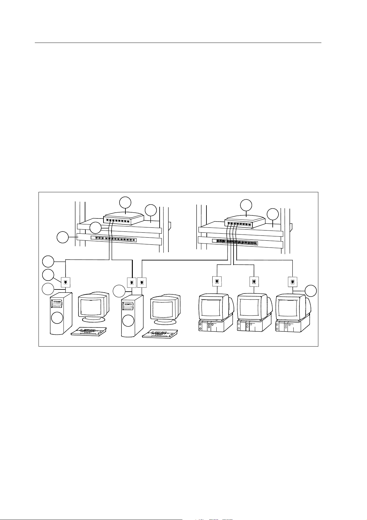
3.3 Horizontal cabling
Use horizontal cabling in cabling bounding to one floor as illustrated in Figure 3-1.
1
2
3
4
7
5
6
8
9
10
2
8
11
Figure 3-1 Horizontal cabling
(1) ViewStation
(2) Mon/IC-Net Cable
(3) Wallbox
(4) Horizontal cable
(5) Horizontal Patch Panel
(6) Patch Cable
(7) 100 Mbps hub
(8) Shelf
(9) 10 Mbps hub
(10) Mon-Net Cable
(11) S/5 Central
Datex-Ohmeda S/5 Central, ViewStation and Network
15
Document No. 8000633-1
3.3.1 Mon/IC-Net cables
Mon/IC-Net cables are work area cables and carry signals between Centrals or ViewStations and
wallboxes both in the monitor network and in the TCP/IP network. The cable type is category 5
unshielded twisted pair, designed to be thin and flexible. The cable is terminated with RJ-45
connectors at both ends, and the coupling method is straight through. Figure 3-2 illustrates a
Mon/IC-Net Cable.
Figure 3-2 Mon/IC-Net Cable
Connecting the Mon/IC-Net cable to Central/ViewStation
1. For the monitor network: connect one cable end to the network connector marked MON on
the rear panel of the Central.
For the Datex-Ohmeda Network: connect one cable end to the network connector marked
TCP/IP on the rear panel of the Central/ViewStation.
2. Connect the other end to the connector on the wallbox.
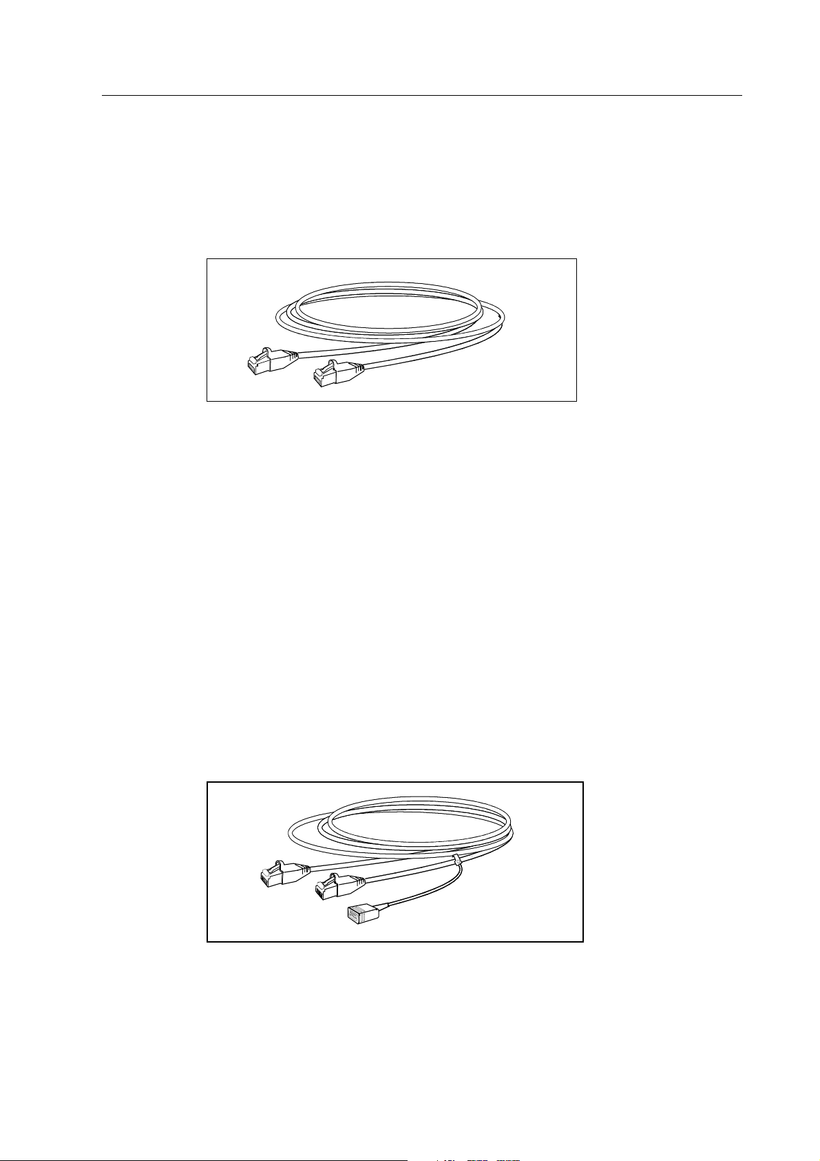
3.3.2 Mon-Net cables
Mon-Net cables are work area cables and carry signals between monitors and wallboxes. The cable
type is category 5 unshielded twisted pair, designed to be thin and flexible. The cable is terminated
with RJ-45 connectors at both ends, and the coupling method is straight through.
The Mon-Net cable includes an identification plug. The plug contains an EEPROM chip with a
unique value to identify the location of the monitor. This location ID is necessary for the network
setup. Figure 3-3 illustrates a Mon-Net Cable.
Figure 3-3 Mon-Net cable
Technical Reference Manual
16
Document No. 8000633-1
Connecting the Mon-Net cable to monitors
1. Connect the connector with the identification plug, to the connector on the rear panel of the
monitor.
2. Connect the identification plug to the connector on the rear panel of the monitor (in the
Network Board, B-NET).
3. Connect the other end to the connector on the wallbox.
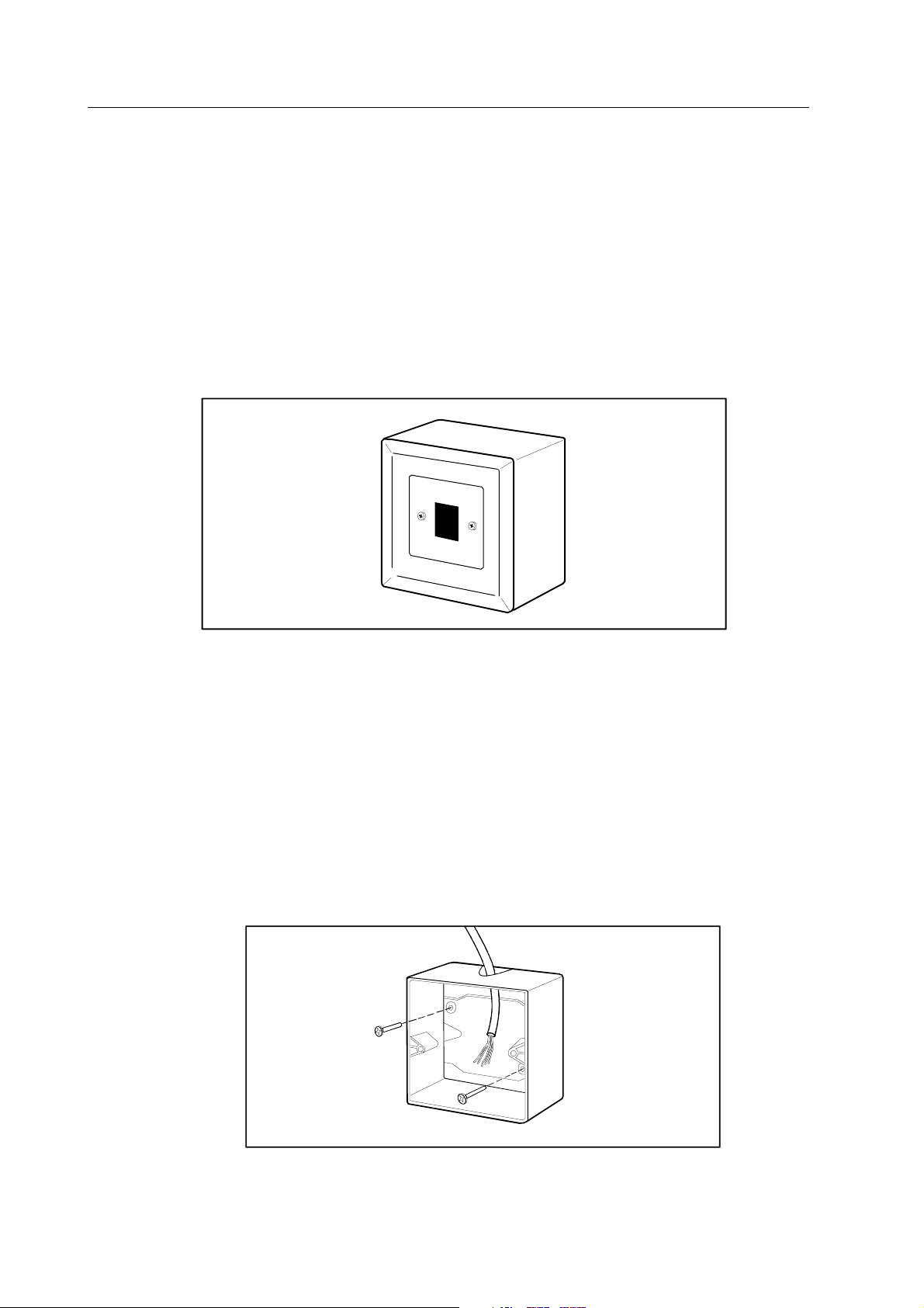
3.3.3 Wallboxes
Wallboxes transfer signals from Mon-Net cables and Mon/IC-Net cables to horizontal cables. The
wallbox consists of one slot suitable for an RJ-45 connector. Figure 3-4 illustrates a wallbox.
N
E
T
Figure 3-4 Wallbox
Labeling the wallbox
Clearly label all wallboxes on both the attachment plate and the center plate. The labeling method
must be flexible to adapt to changes in the wiring. If a labeling method already exists within the
hospital, use it.
Installing the wallbox
1. Drill two holes in the wall at a height of 1.2-1.3 m (3.9-4.3 ft.) for the surface mount box
fastening screws. Pull the horizontal cable through the box. Fasten the box to the wall with
two fastening screws.
NOTE: If you use a wall device outlet box, you do not need the surface mount box.
Datex-Ohmeda S/5 Central, ViewStation and Network
17
Document No. 8000633-1
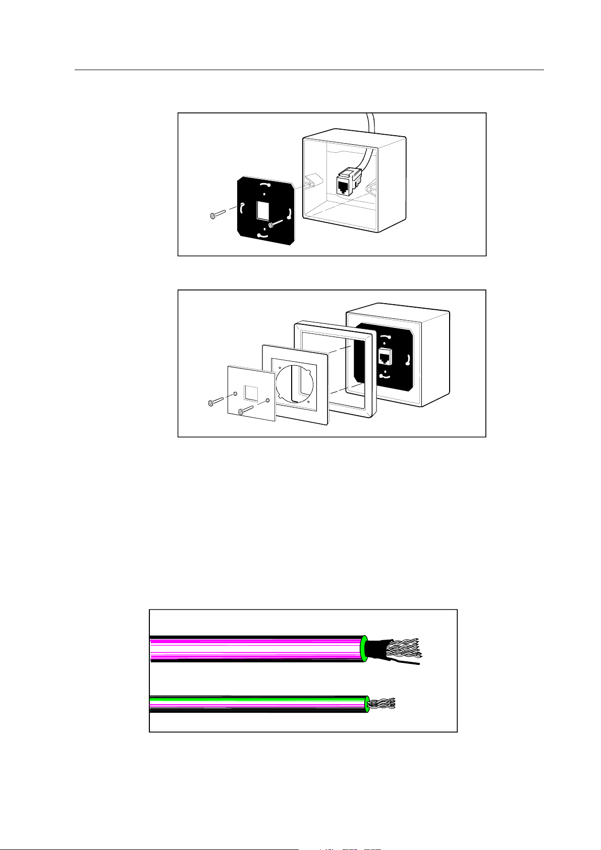
2. Finish the horizontal cable and attach the RJ-45 connector to the attachment plate. Fasten
the plate to the surface mount box with two fastening screws.
3. Place the cover ring and the adaptation ring upon the attachment plate. Pierce the center
plate and fasten the plate to the attachment plate with two fastening screws.
3.3.4 Horizontal cables
Horizontal cables carry signals between wallboxes and horizontal patch panels. The term
"horizontal" is used because the cable runs horizontally along the floor(s) or ceiling(s).
The cable type is category 5 twisted pair, either unshielded or foiled. The unshielded twisted pair
(UTP) is thin and flexible, while the foiled twisted pair (FTP) cable is thick and fixed. The cable jacket
can optionally be standard PVC or plenum. Standard PVC cable is flame resistant to 75 °C while
plenum cable is fire retardant up to temperatures of 200 °C. Use plenum cable instead of
standard PVC in areas where a high degree of fire resistance is required such as heating,
ventilation and air conditioning (HVAC) ducts. Technical data sheets for the horizontal cables are
included in the appendices. Figure 3-5 illustrates horizontal cables.
UTP
FTP
Figure 3-5 Horizontal cables

Technical Reference Manual
18
Document No. 8000633-1
Labeling the horizontal cables
Clearly label all horizontal cables on both the local and remote end. The labeling method must be
flexible to adapt to changes in the wiring. If a labeling method already exists within the hospital,
use it.
Routing the horizontal cables
• Route the cables where they will be concealed and protected from possible damage.
• Do not route the cables in a common cabling enclosure. However, you may ground them
together in a common cabling enclosure.
• Route the cables at an adequate distance from AC power lines, air conditioning systems
and diathermy units, etc., to minimize RF and AC interference. Never route long runs of
cables parallel to AC power lines. Table 3-1 illustrates overall separations for horizontal
cables.
• Avoid routing the cables outside the building especially when prewiring. If you wish to route
cables in this fashion, slope holes bored through exterior walls upward from the outside.
Keep the size of the holes as small as possible and seal the exterior surface after you have
installed the cables.
• Route the cables without any sharp angles. The bend radius of a UTP type cable should not
be less than 8.3 cm (3.3 in.) while the bend radius for a FTP type cable should not be less
than 9.3 cm (3.7 in.).
• Route the cables and install the mounting hardware (roughing-in) after installation of the
electrical power system, but before thermal insulation and wallboards are installed when
performing prewiring.
Table 3-1 Separations for horizontal cables
Voltage source Type of wire Separation Alternative
Electric Supply Bare wire (any voltage), or open wire
over 300 V
1.5 m (5 ft) None
Electric Supply Open wire not over 300 V 5 cm (2 in) (*)
Electric Supply Wire in separate conduit, in armored or
non-metallic shield or ground wire
None N/A
Radio and television Antenna lead-in or ground wire 10 cm (4 in) (*)
Signal or control All types None N/A
CATV Coaxial cables with grounded shielding None N/A
Telecommunication Drop wire, all types 5 cm (2 in) (*)
Neon signs Wire from transformer 15 cm (6 in) None
Lighting systems Lighting rods and wires 1.8 m (6 ft) (**)
(*) When you cannot obtain minimum separations, provide additional protection by means of plastic tube,
wire guard, or two layers of vinyl tape extending 5 cm (2 in.) beyond each side of the wiring being crossed.
(**) If you cannot obtain separations of 1.8 m (6 ft.), separations of least 10 cm (4 in.), are permissible if:
— you make all telecommunication, power, and lighting rod ground connections to a common
metallic cold water pipe that is properly grounded, or
— you use separately driven ground rods for telecommunications, power, and lighting and
bond the ground rods together.
Datex-Ohmeda S/5 Central, ViewStation and Network
19
Document No. 8000633-1
Pulling the horizontal cables
• Pull the cables using 2.5 m (8.2 ft.) long pipes and pull several cables simultaneously.
• Avoid damaging the cables when pulling them. Pulling tension on a TP cable may not
exceed 11.3 kg (25 lb.) to prevent stretching the conductors.
• Be particularly careful when pulling the cables through joists and studs (especially metal
studs) to prevent damage to the cable shield.
• Install a "pull-string" with the cable runs (e.g., inside wall cavities between floors) to
facilitate pulling of future cable runs.
• After the cable is pulled, cut off 1 m (3.3 in.) of the cable end to eliminate possible damage.
Fastening the horizontal cables
• Fasten the cable securely without adversely affecting the insulation.
• Use wire clamps, wire staples, bridle rings and drive rings as fasteners when fastening and
also when changing direction of the cable to hold the cable without any sharp angles. Place
fasteners according to spacing intervals in Table 3-2.
Table 3-2 Typical fasteners and spacing intervals
Fastener Horizontal spacing Vertical spacing Spacing from corner
Wire clamp 40 cm (16 in) 40 cm (16 in) 5 cm (2 in)
Wire staples 18 cm (7 in) 18 cm (7 in) 5 cm (2 in)
Bridle rings 1.2 m (4 ft) 2.5 m (8 ft) 5 to 22 cm
(2 to 8.5 in)
Drive rings 1.2 m (4 ft) 2.5 m (8 ft)
5 to 22 cm
(2 to 8.5 in)
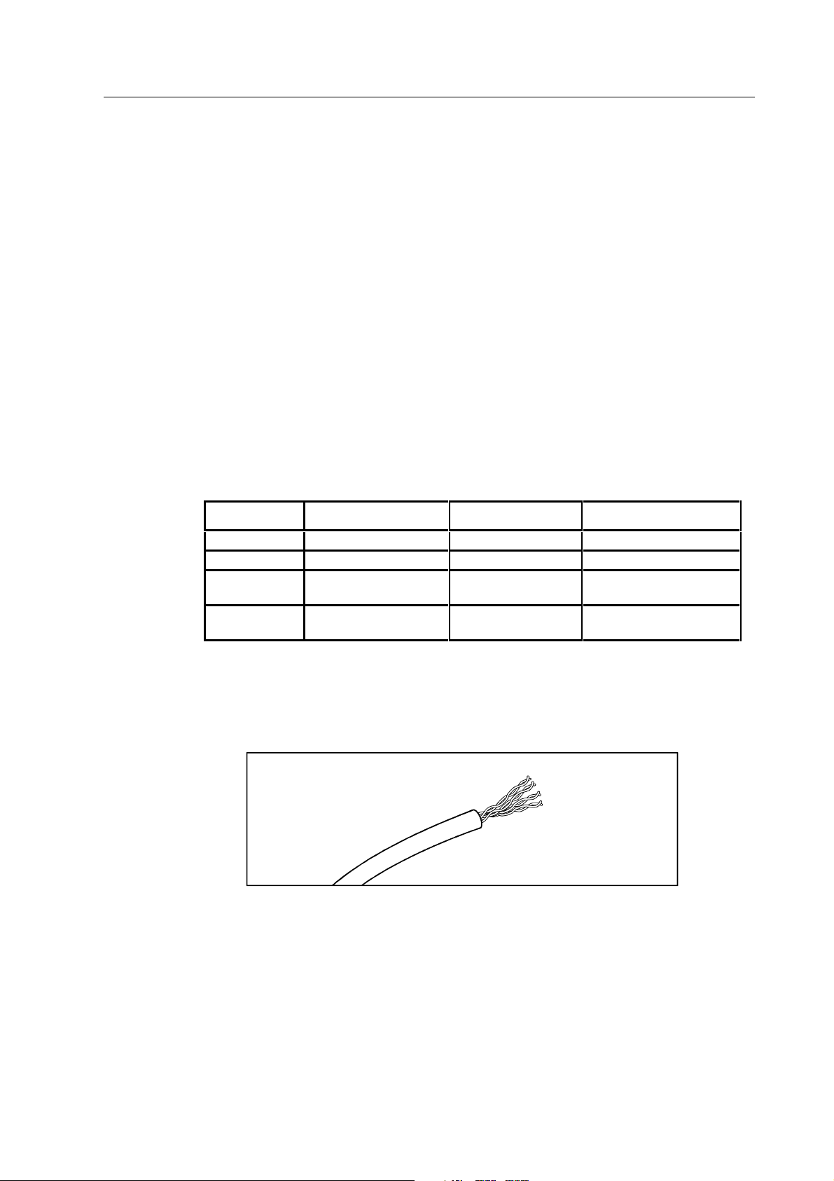
Finishing UTP cables
Finishing UTP cables for wallboxes and patch panels.
1. Strip off approximately 5.0 cm (2 in.) of insulation from the cable end.
Technical Reference Manual
20
Document No. 8000633-1
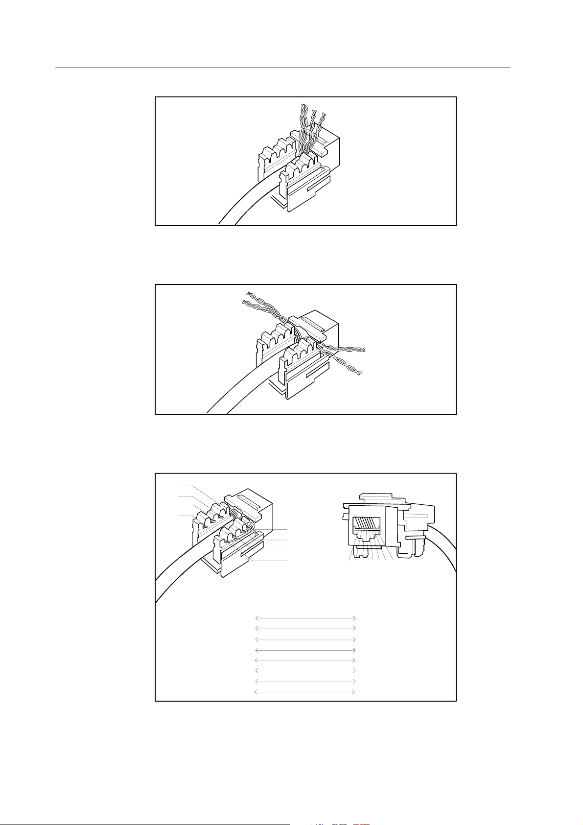
2. Fold the stripped portion upwards and place the cable between the connector blocks.
3. Separate the data wires. Slide orange pair and brown pair, then blue pair and green pair
through opposite openings above the connector blocks. Leave the pairs twisted. The
maximal untwisting must be less than 13 mm (0.5 in.).
4. Pass the wire pairs along the outer surface of the connector blocks. Lay the wires over the
connector pins according to the color code and press the wires into respective pins. Cut off
excess wire and remove the fragments.
1
2
3
4
5
6
7
8
1
2
3
4
5
6
7
8
5
4
3
6
1
2
7
8
Block
Jack
Terminal
WHT/BLU
BLU
WHT/ORG
ORG
WHT/GRN
GRN
WHT/BRN
BRN
1
2
34
5
6
7
8
5. Push back the excess length of cable into the wall cavity.
Datex-Ohmeda S/5 Central, ViewStation and Network
21
Document No. 8000633-1
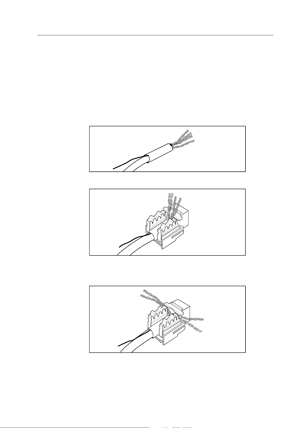
Finishing the FTP cables
Finishing FTP cables for wallboxes:
1. Strip off approximately 8 cm (3.1 in.) of insulation and cable shield from the cable end and
cut off the drain wire.
2. Finish the FTP Cables for Wallboxes as described above about UTP cables starting from the
step 2.
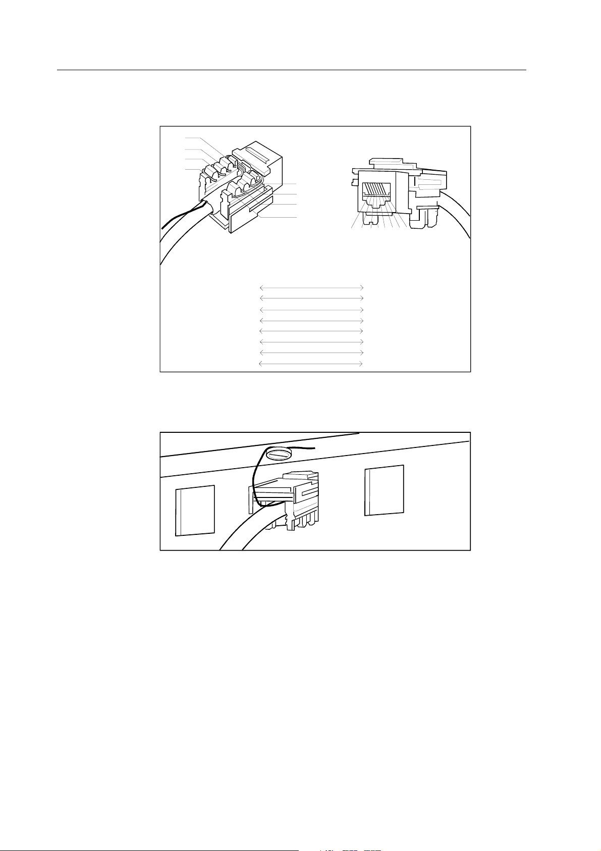
Finishing the FTP cable for Patch Panels
1. Strip off approximately 8.0 cm (3.1 in.) of insulation and shield from the cable end.
Separate the drain wire and isolate the wire with tape.
2. Fold the stripped portion upwards and place the cable between the connector blocks.
3. Separate the data wires. Slide orange pair and brown pair, then blue pair and green pair
through opposite openings above the connector blocks. Leave the pairs twisted. The
maximal untwisting must be less than 13 mm (0.5 in.).
Technical Reference Manual
22
Document No. 8000633-1
4. Pass the data wires along the outer surface of the connector blocks. Lay the wires over the
connector pins according to the color code and press the wires into respective pins. Cut off
excess wire and remove the fragments.
1
2
3
4
5
6
7
8
1
2
3
4
5
67
8
1
2
3
4
5
6
7
8
5
4
3
6
1
2
7
8
Block
Jack
Terminal
WHT/BLU
BLU
WHT/ORG
ORG
WHT/GRN
GRN
WHT/BRN
BRN
5. Unscrew the GND connector screw on the patch panel. Wrap the drain wire(s) around the
screw in the direction the screw tightens and tighten the screws. The cable shield must
make electrical contact with an earth reference at one point only.
6. Push back the excess length of cable into the wall cavity.
Datex-Ohmeda S/5 Central, ViewStation and Network
23
Document No. 8000633-1
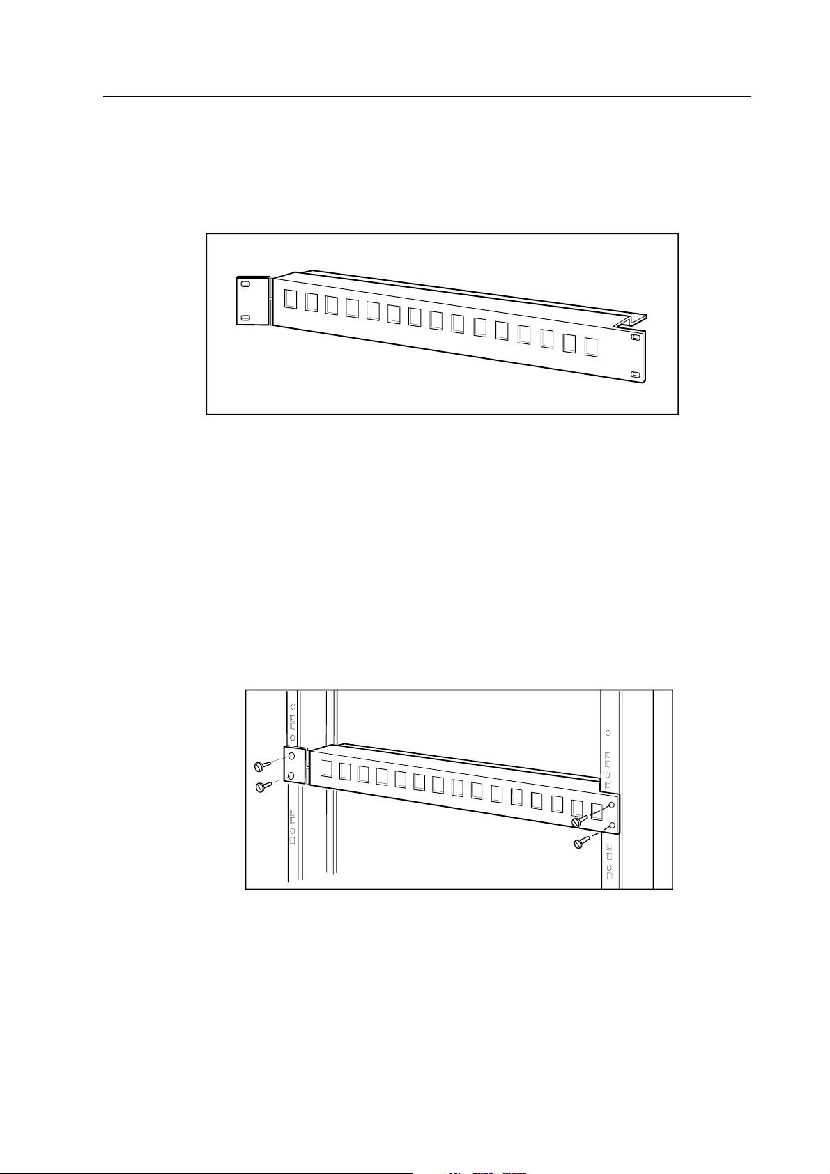
3.3.5 Horizontal patch panels
Horizontal patch panels are used with hubs to transfer signals from horizontal cables to patch
cables. The panel constitutes of 16 slots suitable for RJ-45 connectors. Figure 3-6 illustrates a
horizontal patch panel.
Figure 3-6 Horizontal patch panel
Labeling the patch panel
Clearly label all horizontal patch panel slots. The labeling method must be flexible to adapt to
changes in the wiring. If a labeling method already exists within the hospital, use it.
Installing the patch panel
The horizontal patch panel is equipped for direct mounting to 19" rack mounting hardware. Fasten
the panel to the rack according to the following procedures.
1. Line up the holes on the edges of the panel with the holes on the rack. Attach the panel to
the rack with four fastening screws. Always locate the panel beneath the hub to leave hub
signal lights visible.
2. Finish the horizontal cables and complete the panel by firmly pressing the RJ-45 connectors
into reserved slots of the panel.
Technical Reference Manual
24
Document No. 8000633-1
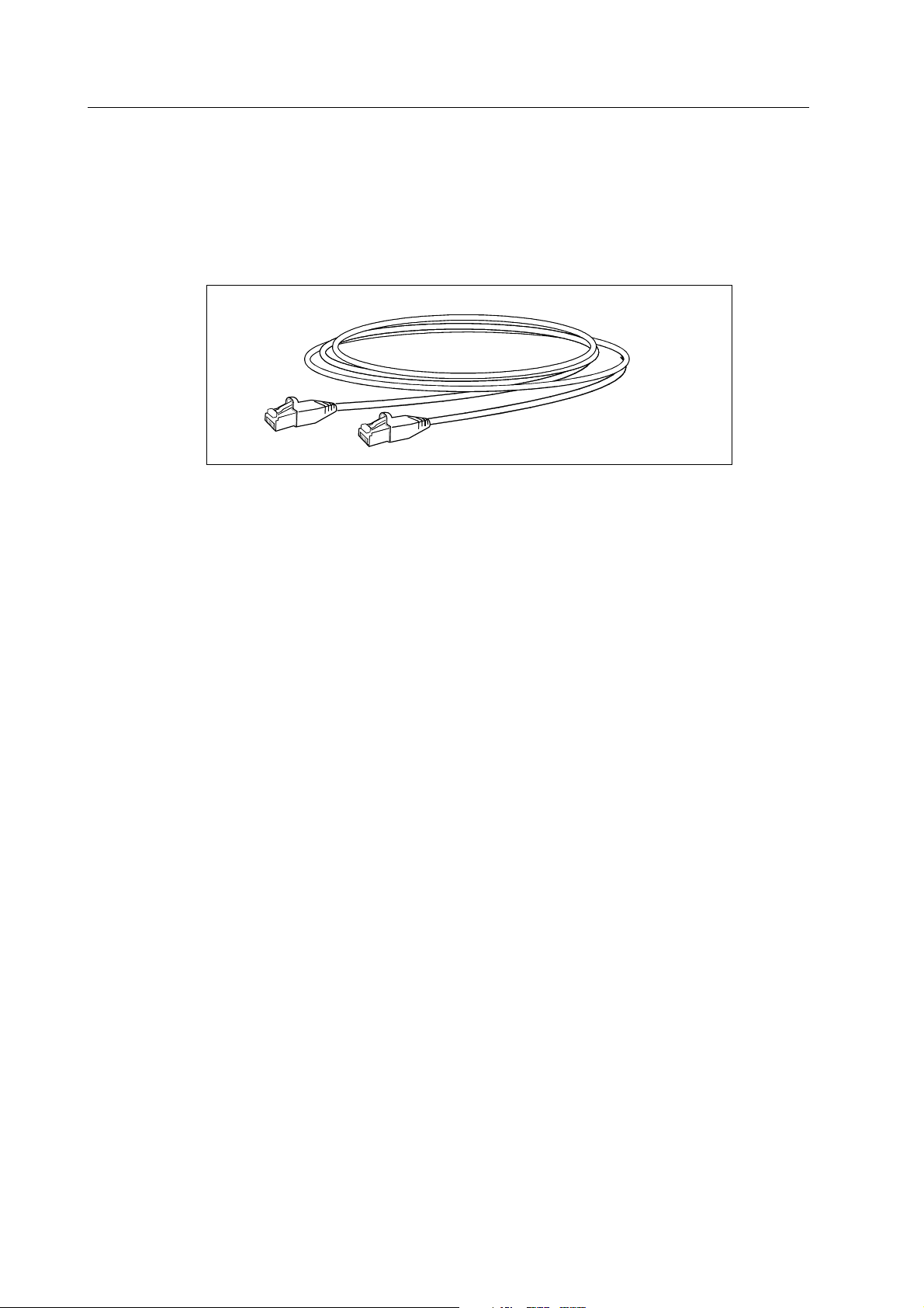
3.3.6 Patch cables
Patch cables are equipment cables that carry the signals between horizontal patch panels and
hubs. The cable type is category 5 unshielded twisted pair, designed to be thin and flexible. The
cable is terminated with RJ-45 connectors at both ends, and the coupling method is straight
through. Figure 3-7 illustrates a patch cable.
Figure 3-7 Patch cable
Connecting the patch cable
1. Connect one cable end to the connector on the patch panel.
2. Connect the other end to the connector on the front panel of the hub.
Loading...