


Excel 210 MRI Compatible Operation and Maintenance Manual
Anesthesia Machine

User Responsibility
This Product will perform in conformity with the description thereof contained in this operating manual and accompanying labels and/or inserts, when assembled, operated, maintained and repaired in accordance with the instructions provided. This Product must be checked periodically. A defective Product should not be used. Parts that are broken, missing, plainly worn, distorted or contaminated should be replaced immediately. Should such repair or replacement become necessary, Datex-Ohmeda recommends that a telephonic or written request for service advice be made to the nearest Datex-Ohmeda Field Service Support Center. This Product or any of its parts should not be repaired other than in accordance with written instructions provided by DatexOhmeda and by Datex-Ohmeda trained personnel. The Product must not be altered without the prior written approval of Datex-Ohmeda’s Quality Assurance Department. The user of this Product shall have the sole responsibility for any malfunction which results from improper use, faulty maintenance, improper repair, damage, or alteration by anyone other than Datex-Ohmeda.
w CAUTION U. S. Federal and Canadian law restrict this device to sale by or on the order of a licensed medical practitioner. Outside the U. S. A. and Canada, check local laws for any restrictions that may apply.
Datex-Ohmeda products have unit serial numbers with coded logic which indicates a product group code, the year of manufacture and a sequential unit number for identification.
AAA A 12345
This alpha character indicates the year of product manufacture
and when the serial number was assigned; “Y” = 1995, “Z” = 1996, “A” = 1997, etc. “I” and “O” are not used.
1001-0809-000 11/20/99

Table of Contents
1/Introduction
Introduction to the Excel MRI Compatible Anesthesia System 1-1
How to use this manual 1-2
Symbols used in the manual or on the equipment 1-3
2/General Information
Identifying Excel MRI components and controls 2-1
Identifying 5125 O2 Monitor components and controls 2-6
3/Set Up
Before starting to setup the system |
3-1 |
|
|
|||
Mounting gas cylinders |
3-1 |
|
|
|
|
|
Mounting the 5125 O2 Monitor |
3-2 |
|
|
|||
Circuit and monitoring connections |
3-4 |
|
|
|||
4/Preoperative Checkout |
|
|
|
|
|
|
Before starting the checkout |
4-1 |
|
|
|
||
MRI compatibility check |
4-1 |
|
|
|
|
|
Initial Checks |
4-2 |
|
|
|
|
|
Checking vaporizer mounting |
4-3 |
|
|
|
||
Checking cylinder and pipeline supplies |
4-3 |
|
||||
Checking vaporizer back pressure |
4-4 |
|
|
|||
Leak checking the low pressure circuitry |
4-4 |
|
||||
Checking the gas flow controls |
4-6 |
|
|
|||
Breathing system checks |
4-7 |
|
|
|
||
5125 O2 Monitor checks |
4-7 |
|
|
|
||
5/Maintenance |
|
|
|
|
|
|
Maintenance schedule |
5-1 |
|
|
|
|
|
Cleaning and sterilization |
5-2 |
|
|
|
||
Cleaning |
5-2 |
|
|
|
|
|
Sterilization 5-3 |
|
|
|
|
|
|
Special precautions for rubber articles |
5-3 |
|||||
O2 sensor maintenance |
5-3 |
|
|
|
|
|
Installing a cartridge or disassembling the O2 sensor for cleaning 5-3 |
||||||
Cleaning and sterilization |
5-6 |
|
|
|||
Replacing the 5125 O2 Monitor battery |
5-7 |
|||||
i
1001-0809-000 11/20/99
i

Table of Contents
6/Troubleshooting
Repair policy 6-1
Problems with the 5125 O2 Monitor 6-1
Calibration and drift 6-1
5125 O2 Monitor alarms 6-2 Pneumatics problems 6-3
7/Illustrated Parts
Excel specific parts 7-1 |
|
MRI Compatible accessories |
7-1 |
5125 O2 Monitor accessories |
7-2 |
Where to find additional part numbers 7-2
Appendix
Excel Pneumatics A-1
Excel MRI System Specifications A-4
Warranty
ii
1001-0809-000 11/20/99
ii

1/Introduction
w WARNING Using an MRI system in conjunction with general anesthesia on cardiac patients, febrile patients, and patients with impaired ability to perspire may present a patient health hazard.
In this section
Introduction to the Excel MRI Compatible Anesthesia System 1-1
How to use this manual 1-2
Symbols used in the manual or on the equipment 1-3
Introduction to the Excel MRI Compatible Anesthesia System
The Datex-Ohmeda commitment to meeting your anesthesia needs continues with the Excel Magnetic Resonance Imaging (MRI) Compatible Excel Anesthesia System.
Basic features
The Excel MRI System includes:
•Three gases, oxygen, nitrous oxide, and air. All gases have pipeline and cylinder connections.
•The 5125 MRI Compatible O2 Monitor with adjustable high and low O2 alarms, and built in battery and hardware self tests.
•A two vaporizer manifold.
MRI Compatibility
The Excel MRI is constructed primarily of non-ferous materials to help prevent attraction to the cryogenic magnets in MRI systems.
The Excel MRI and attached accessories performed to specifications when tested together as a system directly next to an unshielded, 1.5 Tesla MRI unit with a magnetic fringe field below 0.23 Tesla (2300 Gauss).
Approved accessories
A wide variety of Datex-Ohmeda accessories have been approved for use in conjunction with the Excel MRI under test conditions:
w WARNING The MRI compatibility of these accessories applies to specific accessory models and is limited to use as part of the Excel MRI System. None of these accessories have been tested for stand alone use in an MRI environment or in magnetic fringe fields above 0.23 Tesla (2300 Gauss).
•Tec 4 or 5 vaporizers; keyed or funnel fill models.
•GMS Absorber, PEEP valve, and Bain Circuit adapter
•Waste Gas Scavenging Valve
•121 Respirometer
•Standard or free flow suction regulator kits
•Auxiliary oxygen flowmeter
•Flip-up shelf
1-1 |
1001-0809-000 11/20/99 |
1-1 |

1/Introduction
•Storage cabinets
•Dovetail mounted accessories: a 1 x 3.5 inch post with two inch extension; a 12 inch IV Pole; a large case Tycos gauge; and holders and regulators for E-size O2 and N2O cylinders.
Because approval applies only to specific accessory models, consult the Illustrated Parts Section of this manual for Stock Numbers.
Safety features
The Excel MRI includes several important safety features:
•The Datex-Ohmeda Link 25 Proportion Limiting Control System limits the lowest oxygen
concentration that can be delivered on the Excel MRI to a nominal 25% for O2/N2O mixtures at the common gas outlet.
•An audible low O2 supply alarm alerts you if the O2 pressure falls below a nominal 207 kPa (30 psig).
•N2O and air flows stop if O2 supply pressure falls below a nominal 138 kPa (20 psig).
•An interlock mechanism that helps prevent more than one Datex-Ohmeda Tec 4 or Tec 5 vaporizer from being “On” at once. An isolation system also helps prevent fresh gas from entering a vaporizer that is not switched “On.”
•Low battery alarms and built in self tests on the 5125 O2 Monitor.
•Differentiated pipeline and cylinder gauges.
•Gas specific pipeline and cylinder connections.
•A guarded O2 flush button.
•Color coded flow controls and pressure gauges.
Operator convenience
For your convenience, the Excel MRI also features:
•An O2 power outlet
•Full length dovetail accessory mounting.
•A single action brake/footrest.
•Shelf space for additional monitoring.
•Large, easy-running casters and a compact frame.
How to use this manual
This manual covers the Excel MRI System and the MRI Compatible 5125 O2 Monitor. Vaporizers, the GMS Absorber, the Waste Gas Scavenging Valve and other major accessories also have individual operation and maintenance manuals. A complete set of operation and maintenance manuals comes with the Excel MRI System. Datex-Ohmeda recommends that you keep this manual and all related manuals available for reference.
If you are using the system for the first time, read this manual first. Then read the operation and maintenance manuals for the system components. Before you go on to Chapter 2, “General Information,” make sure that you understand the symbols listed at the end of this chapter.
If you have used the Excel MRI before, complete the step-by-step set up procedure in Chapter 3. Then turn to Chapter 4 “Preoperative Checkout,” which is required before using the Excel MRI.
1-2 |
1001-0809-000 11/20/99 |
1-2 |

1/Introduction
Before cleaning the Excel MRI, read Chapter 5, “Maintenance,” carefully. This section also tells you how to change the O2 Monitor battery and assemble and service the O2 sensor (sensor cartridge replacement, disassembly for cleaning).
Chapter 6, “Troubleshooting,” helps you solve problems that may occur with the Excel MRI or the 5125 O2 Monitor. For example, how can you tell if a low pressure leak is due to a vaporizer that you can replace or an internal fault that requires a service call? (If the leak follows a particular vaporizer and the external o-ring is in place, replace the vaporizer.)
Chapter 7, “Illustrated Parts,” tells you how to order replacement parts and accessories. It also lists part numbers for all operation and maintenance manuals associated with the Excel MRI System.
The Appendix lists Excel MRI and 5125 O2 Monitor specifications and describes the internal pneumatic circuitry of the Excel MRI.
Please also take a moment to review the User Responsibility Statement on the inside of the front cover; it describes what is expected of you to maintain the Excel MRI. Also read the Warranty on the back cover; it outlines Datex-Ohmeda’s responsibility in case of a functional defect.
Symbols used in the manual or on the equipment
wWarnings and wCautions tell you about dangerous conditions that can occur if you do not obey all of the instructions in this manual.
Warnings tell you about a condition that can cause injury to the operator or the patient. Cautions tell you about a condition that can cause damage to the equipment. Read and obey all warnings and cautions.
Other symbols replace words on the equipment or in Datex-Ohmeda manuals. No one device or manual uses all of the symbols. These symbols include:
ø
O o q p
œ
†
x
On (power)
Off (power)
Standby
Standby or preparatory state for a part of the equipment
“ON” only for part of the equipment
“OFF” only for part of the equipment
Direct Current
Alternating Current
Protective earth ground
1-3 |
1001-0809-000 11/20/99 |
1-3 |

1/Introduction
yEarth Ground
rFrame or chassis ground
åAlarm silence button
YEquipotential
tVariability
TVariability in steps
+Plus, positive polarity
ËMinus, negative polarity
PLamp, lighting, illumination
NMovement in one direction
ˆMovement in both directions
zLock
ZUnlock
134°C Autoclavable
ÍNon-autoclavable
mType B equipment
µType BF equipment
HType CF equipment
wCaution, ISO 7000-0434
wW Attention, consult accompanying documents, IEC 601-1
ÊThis way up
Dangerous Voltage
1-4 |
1001-0809-000 11/20/99 |
1-4 |

1/Introduction
Ù
REF
SN
Input
Output
Stock Number
Serial Number
Systems with this mark agree with European Council Directive (93/42/EEC) for Medical Devices when they are used as specified in their Operation and Maintenance Manuals. The xxxx is the certification number of the Notified Body used by Datex-Ohmeda’s Quality Systems.
Read top of float
|
Vacuum inlet |
|
Suction bottle outlet |
O2+ |
O2 Flush button |
|
Cylinder |
Isolation transformer
Linkage system
Risk of Explosion
Low pressure leak test
R u U q Q t r
Bag position/ manual ventilation
Open drain (remove liquid)
Close drain
Inspiratory flow
Expiratory flow
O2 sensor connection
Mechanical ventilation
1-5 |
1001-0809-000 11/20/99 |
1-5 |

1/Introduction
<345 kPa
<414 kPa
O2%
O2%
End case
The primary regulator is set to pressure less than 345 kPa
The primary regulator is set to pressure less than 414 kPa
European Union Representative
Low O2 alarm limit switch
High O2 alarm limit switch
Battery test
Circuit test
Test switch
1-6 |
1001-0809-000 11/20/99 |
1-6 |
2/General Information
In this section
Identifying Excel MRI components and controls 2-1
Identifying 5125 O2 Monitor components and controls 2-6
wWARNING The Datex-Ohmeda Excel System must only be used with non-flammable anesthetic agents.
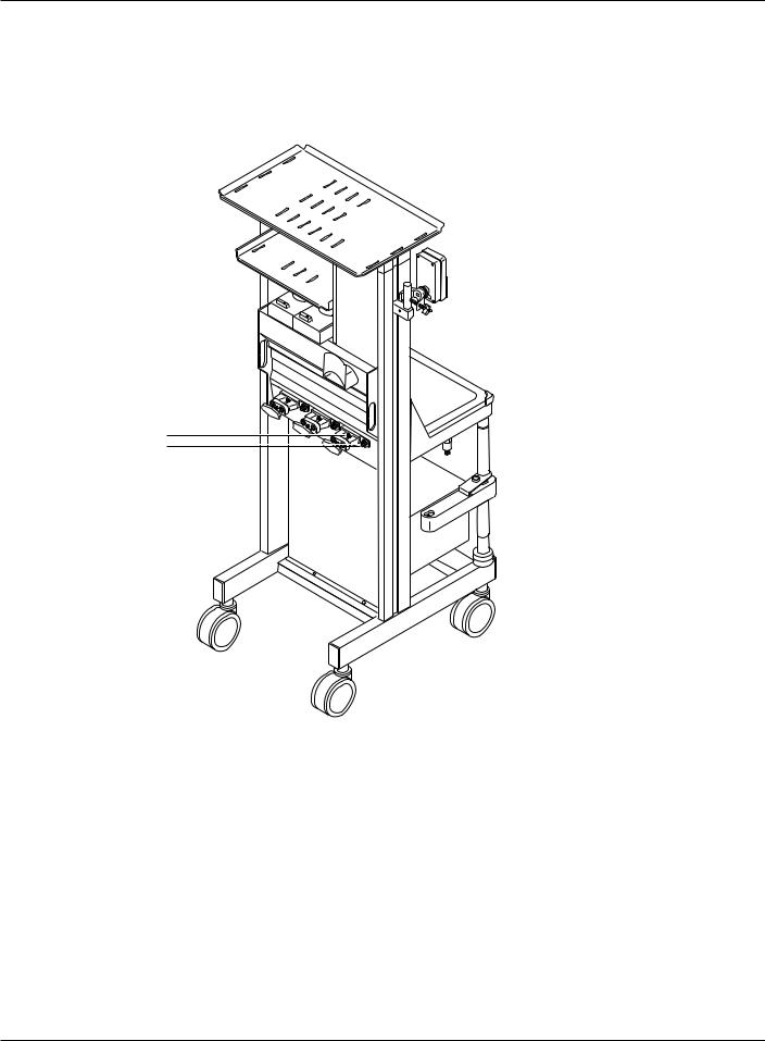
Identifying Excel MRI components and controls
The figures in this chapter, show control locations on Excel MRI System components. For more information on GMS Absorber, or vaporizer controls, refer to the individual operation and maintenance manual.
9 |
|
|
8 |
|
|
|
1 |
|
7 |
2 |
|
3 |
||
|
||
|
4 |
|
6 |
|
|
|
AA.19.039 |
5
1.System Master Switch
2.Flush Button
3.Common Gas Outlet
4.Drawer Cabinet (Optional Accessory)
5.Brake Bar and Footrest
6.Absorber Arm Button
7.O2 Power Outlet
8.Flow Controls
9.5125 O2 Monitor
Figure 2-1
Front view of Excel MRI
2-1 |
1001-0809-000 11/20/99 |
2-1 |

2/General Information
Flow controls
With the system master switch set to “On,” turning a flow control counterclockwise increases flow, turning a flow control clockwise decreases flow. A linkage between the N2O and the O2 flow controls limits the lowest oxygen concentration that can be set on the Excel MRI to a nominal 25% for O2/N2O mixtures at the common gas outlet. Flow ranges are: O2, 200 ml/min to 10 l/min (plus up to two additional turns of the knob); N2O, 0 to 10 l/min (plus up to one additional turn of the knob ); air, 0 to 15 l/min (plus up to one additional turn of the knob).
System master switch
Setting the system master switch to “On” allows gas to flow through the Excel MRI.
Flush button
Pressing the O2 Flush button delivers 45-70 l/min of O2 through the common gas outlet.
Common gas outlet
The common gas outlet delivers anesthetic gases to the patient circuit.
Brake
Push down to keep the Excel MRI from rolling. Lift up to release.
Absorber arm button
Press this button to adjust the height of the absorber arm.
O2 power outlet
Provides drive gas for MRI compatible pneumatic equipment.
2-2 |
1001-0809-000 11/20/99 |
2-2 |
2/General Information
1
2
AA.19.040
1.Cylinder Connection
2.Pipeline Connection
Figure 2-2
Excel MRI (rear)
2-3 |
1001-0809-000 11/20/99 |
2-3 |

2/General Information
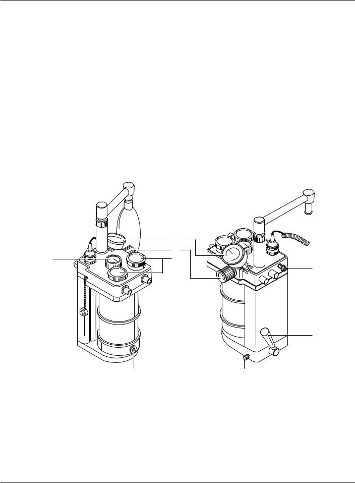
Vaporizer concentration control
Press in the release and turn the concentration knob to the desired agent concentration. The locking lever must be fully clockwise (locked position) or the control will not turn.
Concentration control release
Pressing the release allows you to turn the concentration knob on the vaporizer.
Vaporizer locking lever
When the locking lever is completely counterclockwise, and the vaporizer concentration is set to “Off,” you can mount or remove the vaporizer. Turn the lever clockwise to lock the vaporizer in position.
Vaporizer fill port valve
Opens the fill port valve so that agent can be added or drained.
Vaporizer key lock lever
Holds the fill adapter from the agent bottle in place. To secure the adapter, lower the lever, insert the adapter, and raise the lever.
Vaporizer fill port (spout)
Unscrew and remove the plug to fill or drain vaporizers with funnel fill ports.
Drain Plug
Loosen (do not remove) with hex head portion of spout to drain agent. Tighten drain plug and install spout before use.
8
1
7
AA.13.004 |
AA.13.003 |
2
6
3
54
1.Vaporizer Concentration Control
2.Vaporizer Fill Port (Spout)
3.Drain Plug and Drain Port
4.Vaporizer Fill Port Valve
5.Vaporizer Fill Port (Keyed)
6.Vaporizer Key Lock Lever
7.Concentration Control Release
8.Vaporizer Locking Lever
Figure 2-3
Tec 5 vaporizers
2-4 |
1001-0809-000 11/20/99 |
2-4 |
2/General Information
Absorber drain plug
Unscrew and remove to drain condensate. Replace and tighten before use.
APL valve
This valve limits patient circuit pressure during manual ventilation (bagging).
Absorber check valves
Provide unidirectional flow through the absorber.
Airway pressure gauge
Absorber gauge to display inspiratory pressure.
Absorber release lever
This lever should always be in the lock position during use. The release position lowers the absorber base so that you can remove the canisters.
Absorber mounting knob
Turn completely clockwise to attach the absorber to the mounting pin. Turn counterclockwise to remove the absorber.
Bag/Ventilator switch
This switch on the absorber selects either the bag arm (Bag position) or the ventilator bellows (Vent position).
|
2 |
|
3 |
1 |
4 |
5
AA.15.153 |
AA.15.152 |
6
8 |
7 |
1.Bag/Ventilator Switch
2.Airway Pressure Gauge
3.APL Valve
4.Absorber Check Valves
5.Fresh Gas Input
6.Absorber Release Lever
7.Absorber Mounting Knob
8.Absorber Drain Plug
Figure 2-4
GMS Absorber
2-5 |
1001-0809-000 11/20/99 |
2-5 |

2/General Information
Identifying 5125 O2 Monitor components and controls
Figure 2-5 identifies 5125 O2 Monitor controls and major components.
2
3 |
4 |
1
5125
5 
6
7
8
MD.12.013
MD.12.014 |
MD.02.032 |
14
9 |
11 |
10 |
9 |
10 mV |
MD.12.019 |
per |
|
o2% |
|
Min |
|
RL |
|
20M |
|
1. |
Battery |
13 |
12 |
|
2. |
Calibration Control |
|||
|
|
3.Test Switch
4.O2 Alarm Limits
5.Display
6.Alarm LEDs
7.Battery Power Switch
8.Alarm Silence
9.Sensor Housing
10.O-Ring
11.Sensor Cartridge
12.O2 Sensor Connection
13.Remote Connection (Refer to Appendix for Signal Specifications)
14.Front Panel
Figure 2-5
5125 O2 Monitor controls
2-6 |
1001-0809-000 11/20/99 |
2-6 |

2/General Information
Test switch
Pressing down the top half of the switch (Batt Test) checks the battery condition. Holding down the bottom half of the switch (Circuit Test) checks the 5125 O2 Monitor’s electronic circuitry. For information about using the switch, refer to the section “5125 O2 Monitor checks” at the end of Chapter 4.
Low O2 alarm
Sets the lowest acceptable O2 concentration. O2 concentrations below 18% trigger a low O2 alarm regardless of the alarm limit. Setting the limit below 18% also triggers an alarm.
High O2 alarm
Sets the highest allowed O2 concentration (0 to 99%). Setting the limit to 00% disables the alarm.
Display
Shows the measured O2 concentration and any alarm messages.
Battery Power switch
Switches the 5125 O2 Monitor “On” and “Off.”
Alarm Silence
Pressing the alarm silence button silences all audible alarms, except for low O2, until the next occurrence. Low O2 alarms are silenced for 30 seconds. While the alarm is silenced, any flashing LEDs stay on continuously.
O2 sensor housing and cartridge
The 5125 O2 Monitor uses the standard Datex-Ohmeda O2 sensor. The sensor cartridge is not part of the O2 sensor assembly and must be installed before use. For additional information refer to the section “O2 sensor maintenance” in Chapter 5.
Battery
The 5125 O2 Monitor uses a “C” size, non-magnetic, 3.9 Vdc lithium battery. During operation, the “BATT FAIL” alarm continuously monitors battery strength.
Calibration control
Use the calibration control (CAL) to calibrate the 5125 O2 Monitor for 21% and 100% O2. Refer to “5125 O2 Monitor checks” at the end of Chapter 4.
2-7 |
1001-0809-000 11/20/99 |
2-7 |
 Loading...