


Aespire 7900
User’s Reference Manual—Part 1
System Controls, Operation, Checkout
User Responsibility
This Product will perform in conformity with the description thereof contained in this User’s Reference manual and accompanying labels and/or inserts, when assembled, operated, maintained, and repaired in accordance with the instructions provided. This Product must be checked periodically. A defective Product should not be used. Parts that are broken, missing, plainly worn, distorted, or contaminated should be replaced immediately. Should repair or replacement become necessary, Datex-Ohmeda recommends that a telephonic or written request for service advice be made to the nearest Datex-Ohmeda Customer Service Center. This Product or any of its parts should not be repaired other than in accordance with written instructions provided by Datex-Ohmeda and by Datex-Ohmeda trained personnel.
The Product must not be altered without the prior written approval of Datex-Ohmeda. The user of this Product shall have the sole responsibility for any malfunction which results from improper use, faulty maintenance,
improper repair, damage, or alteration by anyone other than Datex-Ohmeda.
w CAUTION U.S. Federal law restricts this device to sale by or on the order of a licensed medical practitioner. Outside the U.S.A., check local laws for any restriction that may apply.
Datex-Ohmeda products have unit serial numbers with coded logic which indicates a product group code, the year of manufacture, and a sequential unit number for identification.
AAA F 12345
This alpha character indicates the year of product manufacture and when the serial number was assigned; “D” = 2000, “E” = 2001, “F” = 2002, etc. “I” and “O” are not used.
S/5 Aespire, Link-25, Disposable Multi Absorber, Reusable Multi
Absorber, SmartVent, Tec 6 Plus, and Tec 7are registered trademarks of
Datex-Ohmeda Inc.
Other brand names or product names used in this manual are trademarks or registered trademarks of their respective holders.
Table of Contents
1 Introduction
What is an Aespire 7900? . . . . . . . . . . . . . . . . . . . . . . . . . . . . . . . . . . . . . . . 1-2
Symbols used in the manual or on the equipment . . . . . . . . . . . . . . . . . . . . 1-3
2 System Controls and Menus
Anesthesia system controls . . . . . . . . . . . . . . . . . . . . . . . . . . . . . . . . . . . . . . 2-2
Breathing system components . . . . . . . . . . . . . . . . . . . . . . . . . . . . . . . . . . . . 2-5
ACGO . . . . . . . . . . . . . . . . . . . . . . . . . . . . . . . . . . . . . . . . . . . . . . . . . . . . 2-8
Scavenging the ACGO sample flow . . . . . . . . . . . . . . . . . . . . . . . . . . . . 2-9
Scavenging from the external manual breathing circuit . . . . . . . . . . . 2-10
Vaporizer controls . . . . . . . . . . . . . . . . . . . . . . . . . . . . . . . . . . . . . . . . . . . . . 2-10
Ventilator controls . . . . . . . . . . . . . . . . . . . . . . . . . . . . . . . . . . . . . . . . . . . . . 2-12
Optional Features . . . . . . . . . . . . . . . . . . . . . . . . . . . . . . . . . . . . . . . . . 2-12
Control panel . . . . . . . . . . . . . . . . . . . . . . . . . . . . . . . . . . . . . . . . . . . . . 2-12
How to set controls . . . . . . . . . . . . . . . . . . . . . . . . . . . . . . . . . . . . . . . . 2-14
How to use the menu . . . . . . . . . . . . . . . . . . . . . . . . . . . . . . . . . . . . . . . 2-15
Menu map . . . . . . . . . . . . . . . . . . . . . . . . . . . . . . . . . . . . . . . . . . . . . . . 2-16
More about menu functions . . . . . . . . . . . . . . . . . . . . . . . . . . . . . . . . . 2-17
How to change menu settings . . . . . . . . . . . . . . . . . . . . . . . . . . . . . . . . 2-18
Optional auxiliary O2 flowmeter and suction regulators . . . . . . . . . . . . . . . 2-19
3 Operation and Tutorial
Pre-use check list . . . . . . . . . . . . . . . . . . . . . . . . . . . . . . . . . . . . . . . . . . . 3-3
Turn On the system . . . . . . . . . . . . . . . . . . . . . . . . . . . . . . . . . . . . . . . . . . . . . 3-4
Set the alarm loudness . . . . . . . . . . . . . . . . . . . . . . . . . . . . . . . . . . . . . . . . . . 3-5
Show or hide alarm limits and units . . . . . . . . . . . . . . . . . . . . . . . . . . . . . . . . 3-7
Turn the volume alarms on or off . . . . . . . . . . . . . . . . . . . . . . . . . . . . . . . . . . 3-8
Set alarm limits . . . . . . . . . . . . . . . . . . . . . . . . . . . . . . . . . . . . . . . . . . . . . . . . 3-8
Set an audible alarm for circuit leaks . . . . . . . . . . . . . . . . . . . . . . . . . . . . . 3-10
Set Cardiac Bypass . . . . . . . . . . . . . . . . . . . . . . . . . . . . . . . . . . . . . . . . . . . . 3-11
1009-0632-000 |
i |
S/5 Aespire
Start mechanical ventilation . . . . . . . . . . . . . . . . . . . . . . . . . . . . . . . . . . . . |
3-13 |
Stop mechanical ventilation . . . . . . . . . . . . . . . . . . . . . . . . . . . . . . . . . . . . . |
3-14 |
Alarms . . . . . . . . . . . . . . . . . . . . . . . . . . . . . . . . . . . . . . . . . . . . . . . . . . . . . . |
3-15 |
Alarm Tones . . . . . . . . . . . . . . . . . . . . . . . . . . . . . . . . . . . . . . . . . . . . . . |
3-15 |
Alarm Silence . . . . . . . . . . . . . . . . . . . . . . . . . . . . . . . . . . . . . . . . . . . . . |
3-15 |
Alarm Suspend . . . . . . . . . . . . . . . . . . . . . . . . . . . . . . . . . . . . . . . . . . . |
3-15 |
Set the ventilation mode . . . . . . . . . . . . . . . . . . . . . . . . . . . . . . . . . . . . . . . . |
3-16 |
Set ventilator controls . . . . . . . . . . . . . . . . . . . . . . . . . . . . . . . . . . . . . . . . . . |
3-18 |
Optional features . . . . . . . . . . . . . . . . . . . . . . . . . . . . . . . . . . . . . . . . . . |
3-18 |
Ventilator controls . . . . . . . . . . . . . . . . . . . . . . . . . . . . . . . . . . . . . . . . . |
3-18 |
Volume Control mode . . . . . . . . . . . . . . . . . . . . . . . . . . . . . . . . . . . . . . |
3-19 |
Pressure Control mode . . . . . . . . . . . . . . . . . . . . . . . . . . . . . . . . . . . . . |
3-20 |
SIMV mode . . . . . . . . . . . . . . . . . . . . . . . . . . . . . . . . . . . . . . . . . . . . . . . |
3-20 |
PSVPro mode . . . . . . . . . . . . . . . . . . . . . . . . . . . . . . . . . . . . . . . . . . . . . |
3-20 |
Set inspiratory pause (volume modes) . . . . . . . . . . . . . . . . . . . . . . . . |
3-22 |
Set SIMV and PSVPro controls . . . . . . . . . . . . . . . . . . . . . . . . . . . . . . . . . . . |
3-24 |
Silence alarms . . . . . . . . . . . . . . . . . . . . . . . . . . . . . . . . . . . . . . . . . . . . . . . . |
3-26 |
Reading the pressure waveform (Paw) . . . . . . . . . . . . . . . . . . . . . . . . . . . . |
3-27 |
Scales . . . . . . . . . . . . . . . . . . . . . . . . . . . . . . . . . . . . . . . . . . . . . . . . . . . |
3-27 |
Measure circuit compliance . . . . . . . . . . . . . . . . . . . . . . . . . . . . . . . . . . . . . |
3-30 |
Show the service settings . . . . . . . . . . . . . . . . . . . . . . . . . . . . . . . . . . . . . . . |
3-31 |
Measure circuit compliance . . . . . . . . . . . . . . . . . . . . . . . . . . . . . . . . . . . . . |
3-33 |
4 Preoperative Tests
Aespire 7900 Preoperative tests schedules . . . . . . . . . . . . . . . . . . . . . . . . . 4-2
Test Intervals . . . . . . . . . . . . . . . . . . . . . . . . . . . . . . . . . . . . . . . . . . . . . . 4-2
Test devices . . . . . . . . . . . . . . . . . . . . . . . . . . . . . . . . . . . . . . . . . . . . . . . 4-3
Inspect the System . . . . . . . . . . . . . . . . . . . . . . . . . . . . . . . . . . . . . . . . . . . . . 4-4
Power failure alarm test . . . . . . . . . . . . . . . . . . . . . . . . . . . . . . . . . . . . . . . . . 4-5
Minimize alarms (optional) . . . . . . . . . . . . . . . . . . . . . . . . . . . . . . . . . . . . . . . 4-5
Pipeline and cylinder tests . . . . . . . . . . . . . . . . . . . . . . . . . . . . . . . . . . . . . . . 4-6
Flow control tests . . . . . . . . . . . . . . . . . . . . . . . . . . . . . . . . . . . . . . . . . . . . . . . 4-7
Vaporizer installation . . . . . . . . . . . . . . . . . . . . . . . . . . . . . . . . . . . . . . . . . . . 4-9
Vaporizer back pressure test . . . . . . . . . . . . . . . . . . . . . . . . . . . . . . . . . . . . 4-10
Low-pressure leak test . . . . . . . . . . . . . . . . . . . . . . . . . . . . . . . . . . . . . . . . . 4-11
Negative low-pressure
leak test . . . . . . . . . . . . . . . . . . . . . . . . . . . . . . . . . . . . . . . . . . . . . . . . . 4-11
ii |
1009-0632-000 |
ISO 5358 or BSI standard positive low-pressure
leak test . . . . . . . . . . . . . . . . . . . . . . . . . . . . . . . . . . . . . . . . . . . . . . . . . 4-13 Alarm tests . . . . . . . . . . . . . . . . . . . . . . . . . . . . . . . . . . . . . . . . . . . . . . . . . . . 4-14 Breathing system tests . . . . . . . . . . . . . . . . . . . . . . . . . . . . . . . . . . . . . . . . . 4-16 Monitor and ventilator tests . . . . . . . . . . . . . . . . . . . . . . . . . . . . . . . . . . . . . 4-18
Index
Warranty
1009-0632-000 |
iii |
S/5 Aespire
iv |
1009-0632-000 |
1 Introduction
In this section What is an Aespire 7900? . . . . . . . . . . . . . . . . . . . . . . . . . . . . . . . . . . . . . . . 1-2 Symbols used in the manual or on the equipment . . . . . . . . . . . . . . . . . . . . 1-3
1009-0632-000 |
1-1 |
Aespire 7900
What is an Aespire 7900?
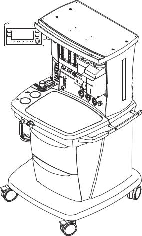
The Aespire 7900 is a compact, integrated and intuitive anesthesia delivery system. The ventilator portion provides mechanical ventilation for patients during surgery as well as monitoring and displaying various patient parameters.
The system uses a microprocessor-controlled ventilator with internal monitors, electronic PEEP, Volume Mode, and other optional features. A serial interface permits communication to cardiovascular and respiratory gas monitoring.
Illustrations in this manual may not cover all types of options available. Other equipment may be attached to the system on the top shelf or on the side dovetail rails. Consult with your Datex-Ohmeda representative for details about systems available in your location.
The Aespire 7900 is not suitable for use in an MRI environment.
Figure 1-1 • Aespire 7900 example
1-2 |
1009-0632-000 |
1 Introduction
Symbols used in the manual or on the equipment
wWARNINGS and wCAUTIONS tell you about dangerous conditions that can occur if you do not follow all instructions in this manual. Read and follow all warnings and cautions.
WARNINGS tell about a condition that can cause injury to the operator or the patient.
CAUTIONS tell about a condition that can cause damage to the equipment.
A Note provides additional information to clarify a statement in text.
An Important statement is similar to a Note, but provides a comment of greater emphasis.
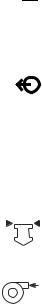
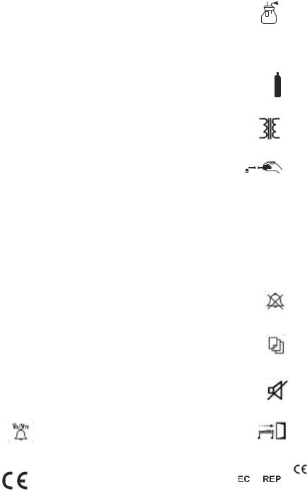
Other symbols replace words on the equipment or in Datex-Ohmeda manuals.
No one device or manual uses all of the symbols. These symbols include:
øOn (power)
O Off (power)
o Standby
qStandby or preparatory state for part of the equipment
p |
“ON” only for part of the equipment |
œ |
“OFF” only for part of the equipment |
† |
Direct current |
∏ |
Alternating current |
x |
Protective earth ground |
y |
Earth ground |
r |
Frame or chassis ground |
å |
Alarm silence button |
Y |
Equipotential |
t |
Variability |
Í
m
µ
H
w wW
N
N
π
≈
REF
SN
R
Not autoclavable
Type B equipment
Type BF equipment
Type CF equipment
Caution, ISO 7000-0434
Attention, refer to product instructions, IEC 601-1.
This way is up.
Dangerous Voltage
Input
Output
Stock Number
Serial Number
Bag position/ manual ventilation
Read top of float
T Variability in steps |
Vacuum inlet |
1009-0632-000 |
1-3 |
Aespire 7900
+ Plus, positive polarity |
|
Suction bottle outlet |
|||
- |
Minus, negative polarity |
O2+ |
O2 Flush button |
||
|
|
||||
P Lamp, lighting, illumination |
|
Cylinder |
|||
N Movement in one direction |
|
Isolation transformer |
|||
ˆ Movement in two directions |
|
Low pressure leak test |
|||
z Lock |
r Mechanical ventilation |
||||
Z Unlock |
UClose drain |
||||
134°C |
Autoclavable |
Q Expiratory flow |
|||
uOpen drain (remove liquid) |
|
Alarm silence touch key |
|||
q Inspiratory flow |
|
Menu touch key |
|||
t |
O |
2 |
sensor connection |
|
Alarm silence touch key |
|
|
|
(Tec 6) |
||
|
Volume alarms On/Off touch key |
|
End case touch key |
||
|
Systems with this mark agree with the |
|
|
European Union Representative |
|
European Council Directive (93/42/EEC) for |
|
|
|
XXXX |
Medical Devices when they are used as |
|
|
|
|
|
|
||
specified in their Operation and Maintenance |
|
|
|
|
|
|
|
|
|
|
Manuals. The xxxx is the certification number |
|
|
|
|
of the Notified Body used by Datex-Ohmeda’s |
|
|
|
|
Quality Systems. |
|
|
|
1-4 |
1009-0632-000 |
2 System Controls and Menus
In this section Anesthesia system controls . . . . . . . . . . . . . . . . . . . . . . . . . . . . . . . . . . . . . . 2-2 Breathing system components . . . . . . . . . . . . . . . . . . . . . . . . . . . . . . . . . . . . 2-5 Vaporizer controls . . . . . . . . . . . . . . . . . . . . . . . . . . . . . . . . . . . . . . . . . . . . . 2-10 Ventilator controls . . . . . . . . . . . . . . . . . . . . . . . . . . . . . . . . . . . . . . . . . . . . . 2-12 Optional auxiliary O2 flowmeter and suction regulators . . . . . . . . . . . . . . . 2-19
1009-0632-000 |
2-1 |
Aespire 7900
Anesthesia system controls
wWARNING Explosion Hazard. Do not use S/5 Aespire systems with flammable anesthetic agents.
wWARNING Do not use antistatic breathing tubes or masks. They can cause burns if you use them near high frequency surgical equipment.
3 |
|
|
2 |
4 |
|
5 |
||
|
||
1 |
6 |
10
9 |
7, 8 |
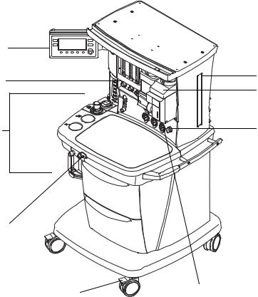
1.Breathing system
2.Flow controls
3.Ventilator / monitoring display
4.Dovetail rails
5.Vaporizer
6.System switch
7.Pipeline pressure gauge(s) (upper row)
8.Cylinder pressure gauge(s) (lower row)
9.Brake
10.O2 flush button
Figure 2-1 • Aespire (front view)
2-2 |
1009-0632-000 |
2 System Controls and Menus
Figure 2-1 shows these controls on the front of the S/5 Aespire.
Item |
|
Description |
||
|
|
|
|
|
2 |
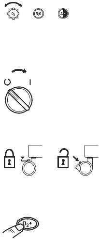
Flow controls |
Turn the control counterclockwise to increase the flow |
||
|
|
and clockwise to decrease. The system switch must |
||
|
|
be On for gas to flow. |
||
|
|
|
|
|
|
|
|
|
|
|
|
|
|
|
7 |
System switch |
Set the switch to the on (|) position to permit gas flow |
|||
|
|
and to turn on the system. |
|||
|
|
|
|
|
|
|
|
|
|
|
|
|
|
|
|
|
|
|
|
|
|
|
|
|
|
|
|
|
|
9 |
Brake |
Push down to lock. Lift to release. |
|
||||||||
|
|
|
|
|
|
|
|
|
|
|
|
|
|
|
|
|
|
|
|
|
|
|
|
|
|
|
|
|
|
|
|
|
|
|
|
|
|
|
|
|
|
|
|
|
|
|
|
|
|
|
|
|
|
|
|
|
|
|
|
|
|
|
|
|
|
|
|
|
|
|
|
|
|
|
|
|
|
|
|
|
|
|
|
10 |
O2 flush button |
Push the O2 flush button to supply high flows of O2 to |
||
|
|
the breathing system. |
||
|
|
|
|
|
|
|
|
|
|
|
|
|
|
|
1009-0632-000 |
2-3 |
Aespire 7900
1
2
7
6
5
4
3
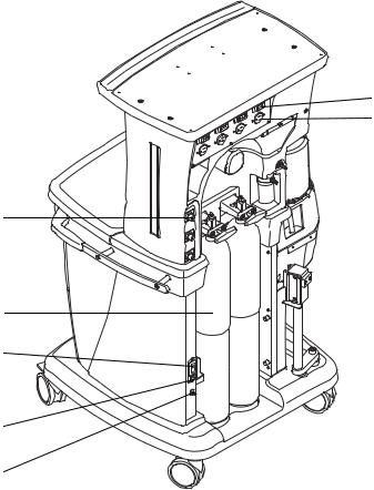
1.Circuit Breaker for Electrical Outlet
2.Electrical Outlet (optional)
3.Equipotential Stud
4.Mains Inlet
5.System Circuit Breaker
6.Cylinder(s) (optional)
7.Pipeline Connection(s)
Figure 2-2 • Aespire rear view
2-4 |
1009-0632-000 |
2 System Controls and Menus
Breathing system components
 19
19
17
16
15
14
13
12
11
10
9
18
8 |
7 |
6 |
5 |
4 |
3 |
|
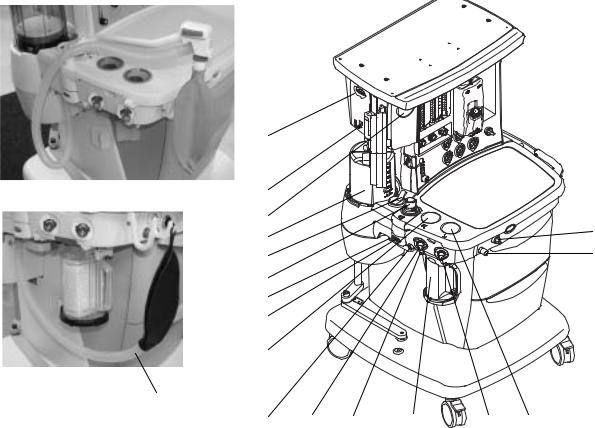
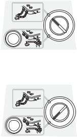
1.Auxiliary common gas outlet (ACGO) switch
2.ACGO
3.Inspiratory check valve (unidirectional valve)
4.Inspiratory flow sensor / patient connection (circuit connections)
5.Canister (carbon dioxide absorbent)
6.Canister release
7.Expiratory flow sensor / patient connection (circuit connections)
8.Leak test plug
9.Expiratory check valve (unidirectional valve)
10.Breathing system release
11.Manual bag port
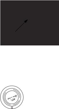
12.APL (adjustable pressure-limiting) valve
13.Bag/mechanical ventilation switch
14.Bellows assembly (mechanical ventilation)
15.Pressure gauge (airway)
16.Sample gas return port
17.Serial port
18.Manual Bag (optional; no bag arm)
19.Bag arm (optional)
Figure 2-3 • Breathing system parts
1
2
1009-0632-000 |
2-5 |
Aespire 7900
Figure 2-3 shows these controls on the front of the S/5 Aespire.
Item |
|
Description |
||
|
|
|
|
|
1 |
Auxiliary Common |
Sends fresh gas to the ACGO when the switch is |
||
|
Gas Outlet switch |
activated. The ACGO may be used to provide fresh |
||
|
(ACGO) |
gas to an external manual breathing circuit. |
||
|
|
Mechanical ventilation is not available when the |
||
|
|
auxiliary outlet is selected and a medium priority |
||
|
|
alarm will sound and a message “Aux Gas Outlet On” |
||
|
|
is displayed. Pressure and volume monitoring are |
||
|
|
not available when the ACGO is selected. Fresh gas |
||
|
|
oxygen monitoring is available when the ACGO is |
||
|
|
selected. |
||
|
|
The ACGO should not be used to drive external |
||
|
|
ventilators or for jet ventilation. |
||
|
|
Breathing system selected: |
||
|
|
|
|
|
|
|
|
|
|
|
|
|
|
|
Auxiliary outlet selected:
|
|
|
|
|
|
|
|
|
|
|
|
4 & 7 Flow sensor |
Flow sensors provide volume measurements for |
||
|
some monitoring functions. All systems have flow |
||
|
sensors in both positions of the flow sensor module. |
||
|
|
|
|
2-6 |
1009-0632-000 |
|
|
|
2 System Controls and Menus |
||
Item |
|
Description |
|||
|
|
|
|
|
|
6 |
Canister release |
Push to remove the canister. This allows the |
|||
|
|
breathing system to vent to the room. Be sure to hold |
|||
|
|
the canister by the handle before releasing the |
|||
|
|
canister. |
|||
|
|
Note: Always do a leak test after operating the |
|||
|
|
canister release. |
|||
|
|
|
|
|
|
|
|
|
|
|
|
|
|
|
|
|
|
12 |
APL valve |
Adjusts breathing system pressure limit during |
|
|
manual ventilation. The scale shows approximate |
pressures. Above 30 cm H2O, you will feel clicks as the knob turns. Turn clockwise to increase. The following example setting is at about 20 cm H2O:
M NI
70
30
20
|
|
|
|
1009-0632-000 |
|
2-7 |
|
Aespire 7900
Item |
|
Description |
||||
|
|
|
|
|
|
|
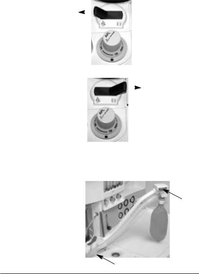
13 |
Bag / Mechanical |
Selects between manual ventilation (bag) or |
||||
|
Ventilation switch |
mechanical ventilation (ventilator). |
||||
|
|
Mechanical ventilation Off (gas to bag): |
||||
|
|
|
|
|
|
|
|
|
|
|
|
|
|
|
|
|
|
|
|
|
Mechanical ventilation On (gas to bellows):
|
|
|
|
|
|
|
|
|
|
|
|
|
|
|
|
|
|
17 |
Bag arm (optional) Squeeze at (1) to raise or lower the arm. The Bag arm |
||||
|
rotates at (2). |
||||
1
2
ACGO When you operate a breathing apparatus with fresh gas from the ACGO:
•Mechanical ventilation is not available.
•The pressure gauge, Bag/Vent switch, APL valve, and bag arm are not part of the external circuit.
•Volume and pressure monitoring are not available.
•O2 monitoring of fresh gas is available automatically when the ACGO is selected if the system has the O2 monitoring option.
2-8 |
1009-0632-000 |
2 System Controls and Menus
•Fresh gas oxygen concentration is displayed on the ventilation screen. Set alarm limits appropriately. Note that fresh gas oxygen concentration
may not reflect FiO2 in rebreathing circuits such as the Mapleson series. Use an external O2 monitor if using a rebreathing circuit on ACGO.
•A sample of the fresh gas is diverted to the O2 cell in the breathing system.
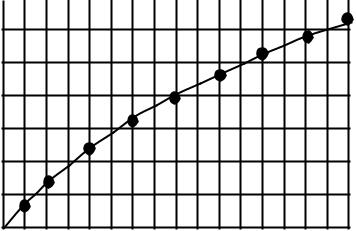
•The sample flow to the O2 sensor is dependent on the pressure in the external circuit. The sample flow reduces the fresh gas flowrate to the external breathing circuit as shown in the graph.
•Do not use an external ventilator on the ACGO.
•Do not use the ACGO to drive external ventilators or for jet ventilation.
Estimate the mean pressure required for ventilation and determine a mean sample flow rate from the graph:
Scavenging the ACGO
sample flow
3
2
L/min
1
10 |
20 |
30 |
40 |
50 |
60 |
70 |
80 |
cm H2 0
Figure 2-4 • Back pressure (cm H20) vs. flow to O2 sensor (L/min)
If the external manual breathing circuit is to be used with N2O or volatile anesthetics, the sample flow should be scavenged.
1.Occlude the patient circuit of the breathing system by using the leak test plug located to the rear of the expiratory port.
2.Check for clinically correct settings. Set the Bag to Vent switch to the ventilator mode. Alternatively set the Bag to Vent switch to the bag mode and set the APL to MIN and attach a bag.
3.The bellows, or bag, will fill slowly with the fresh gas sample flow and then spill to the AGSS.
1009-0632-000 |
2-9 |

Aespire 7900
Scavenging from the external manual breathing circuit
If the external manual breathing circuit is to be used with N2O or volatile anesthetics, the exhaust should be scavenged.
An auxiliary inlet is available for active AGSS units. It provides a 30 mm male connection into the auxiliary port under the breathing system.
•The auxiliary inlet is a convenience inlet to the air brake of active AGSS units. There is a reservoir to capture exhaust flows higher than the extract flow.
For all AGSS, a separate exhaust hose is necessary from the external manual circuit to the disposal point.
Vaporizer controls
Refer to the description in this section and the vaporizer operation and maintenance manual for more detailed information on the vaporizer.
Figure 2-5 shows the vaporizer controls.
1
2
3
4
1.Lock Lever
2.Concentration Control and Release
3.Tec 6 Plus
4.Tec 7
Figure 2-5 • Vaporizer controls
Item |
|
Description |
|||
|
|
|
|
|
|
1 |
Lock lever |
Turn the lever fully clockwise to lock the vaporizer in |
|||
|
|
position. |
|||
|
|
|
|
|
|
|
|
|
|
|
|
|
|
|
|
|
|
|
|
|
|
|
|
2-10 |
1009-0632-000 |
|
|
|
|
|
2 System Controls and Menus |
Item |
|
Description |
|||
|
|
|
|
|
|
2 |
Concentration |
Push the release and turn the concentration control |
|||
|
control and release |
to set the agent concentration. The Tec 6 Plus |
|||
|
|
concentration control does not turn as long as the |
|||
|
|
warm-up indicator is on. |
|||
|
|
|
|
|
|
|
|
|
|
|
|
|
|
|
|
|
|
|
|
|
|
|
|
|
|
|
|
|
|
1009-0632-000 |
2-11 |

Aespire 7900
Ventilator controls
Optional Features
Control panel
The Aespire 7900 can be equipped with several optional ventilation functions. References made in this manual to SIMV and PSVPro modes, are only applicable to systems equipped with these functions.
Ventilator controls include:
•Touch keys
•Menu screens
•A control knob
1 |
2 |
3 |
13
12 11 |
10 |
9 |
8 |
7 |
1.Alarm silence (key) 2.Alarm message (display)
3.Volume alarms On/Off (key) 4.Menu key
5.Breathing circuit module (display) 6.Control knob
7.Control setting 8.Selection key 9.Ventilation mode (display)
10.Ventilator status (On or Off) 11.Mains indicator
12.End Case (key) 13.Measured values
AB.90.025
4
5
6
Figure 2-6 • SmartVent controls and monitored data
All but two of the controls for the ventilator are located on the Ventilation/
Monitoring display. The two controls are:
2-12 |
1009-0632-000 |

2 System Controls and Menus
•The system switch, which powers the ventilator.
•The Bag/Vent switch, which starts and stops mechanical ventilation.
|
Item |
Description |
|
|
|
||||||||||||||||||||||||||||||||||
|
|
|
|
|
|
|
|
|
|
|
|
|
|
|
|
|
|
|
|
|
|
|
|
|
|
|
|
|
|
|
|
|
|
|
|
|
|
|
|
|
Menu key |
Shows the main menu. |
|
|
|
||||||||||||||||||||||||||||||||||
|
|
|
|
|
|
|
|
|
|
|
|
|
|
|
|
|
|
|
|
|
|
|
|
|
|
|
|
|
|
|
|
|
|
|
|
|
|
|
|
|
|
|
|
|
|
|
|
|
|
|
|
|
|
|
|
|
|
|
|
|
|
|
|
|
|
|
|
|
|
|
|
|
|
|
|
|
|
|
AB.90.036 |
|
|
|
|
|
|
|
|
|
|
|
|
|
|
|
|
|
|
|
|
|
|
|
|
|
|
|
|
|
|
|
|
|
|
|
|
|
|
|
|
|
|
|
|
|
|
|
|
|
|
|
|
|
|
|
|
|
|
|
|
|
|
|
|
|
|
|
|
|
|
|
|
|
|
|
|
|
|
|
|
|
|
|
|
|
|
|
|
|
|
|
|
|
|
|
|
|
|
|
|
|
|
|
|
|
|
|
|
|
|
|
|
|
|
|
|
|
|
|
|
|
|
|
|
|
|
|
|
|
|
|
|
|
|
|
|
|
|
|
|
|
|
|
|
|
|
|
|
|
|
|
|
|
|
|
|
|
|||
|
|
|
|
|
|
|
|
|
|
|
|
|
|
|
|
|
|
|
|
|
|
|
|
|
|
|
|
|
|
|
|
|
|
|
|
|
|
|
|
|
|
|
|
|
|
|
|
|
|
|
|
|
|
|
|
|
|
|
|
|
|
|
|
|
|
|
|
|
|
|
|
|
|
|
|
|
|
|
|
|
|
|
|
|
|
|
|
|
|
|
|
|
|
|
|
|
|
|
|
|
|
|
|
|
|
|
|
|
|
|
|
|
|
|
|
|
|
|
|
|
|
|
|
|
|
|
|
|
|
|
|
|
|
|
|
|
|
|
|
|
|
|
|
|
|
|
|
|
|
|
|
|
|
|
|
|
|
|
|
|
|
|
|
|
|
|
|
|
|
|
|
|
|
|
|
|
|
|
|
|
|
|
|
|
|
|
|
|
|
|
|
|
|
|
|
|
|
|
|
|
|
|
|
|
|
|
|
|
|
|
|
|
|
|
|
|
|
|
|
|
|
|
|
|
|
|
|
|
|
|
|
|
|
|
|
|
|
|
|
|
|
|
|
|
|
|
|
|
|
|
|
|
|
|
|
|
|
|
|
|
|
|
|
|
|
|
|
|
|
|
|
|
|
|
|
|
|
|
|
|
Alarm silence key |
Silences most alarms for 120 seconds. |
|
|
|
||||||||||||||||||||||||||||||||||
|
and indicator |
|
|
|
|
|
|
|
|
|
|
|
|
|
|
|
|
|
|
|
|
|
|
|
|
|
|
|
|
|
|
|
|
|
|
|
|
|
|
|
|
Pushing the key when no alarm is active pre-silences low |
|||||||||||||||||||||||||||||||||||||
|
|
and medium priority alarms, except Minimum Monitoring, |
|||||||||||||||||||||||||||||||||||||
|
|
for 90 seconds. |
|
|
|
||||||||||||||||||||||||||||||||||
|
|
The "No O2 Pressure" alarm cannot be silenced. |
|
|
|
||||||||||||||||||||||||||||||||||
|
|
|
|
|
|
|
|
|
|
|
|
|
|
|
|
|
|
|
|
|
|
|
|
|
|
|
|
|
|
|
|
|
|
|
|
|
|
AB.29.004 |
|
|
|
|
|
|
|
|
|
|
|
|
|
|
|
|
|
|
|
|
|
|
|
|
|
|
|
|
|
|
|
|
|
|
|
|
|
|
|
||
|
|
|
|
|
|
|
|
|
|
|
|
|
|
|
|
|
|
|
|
|
|
|
|
|
|
|
|
|
|
|
|
|
|
|
|
|
|
||
|
|
|
|
|
|
|
|
|
|
|
|
|
|
|
|
|
|
|
|
|
|
|
|
|
|
|
|
|
|
|
|
|
|
|
|
|
|
||
|
|
|
|
|
|
|
|
|
|
|
|
|
|
|
|
|
|
|
|
|
|
|
|
|
|
|
|
|
|
|
|
|
|
|
|
|
|
||
|
|
|
|
|
|
|
|
|
|
|
|
|
|
|
|
|
|
|
|
|
|
|
|
|
|
|
|
|
|
Remaining |
|
||||||||
|
|
|
|
|
|
|
|
|
|
|
|
|
|
|
|
|
|
|
|
|
|
|
|
|
|
|
|
|
|
|
|
|
|||||||
|
|
|
|
|
|
|
|
|
|
|
|
|
|
|
|
|
|
|
|
|
|
|
|
|
|
|
|
|
|
silence time |
|
|
|
||||||
|
|
|
|
|
|
|
|
|
|
|
|
|
|
|
|
|
|
|
|
|
|
|
|
|
|
|
|
|
|
|
|
|
|
|
|
|
|
|
|
|
Volume alarm key |
Turns volume alarms on and off. |
|
|
|
||||||||||||||||||||||||||||||||||
|
and status |
|
|
|
|
|
|
|
|
|
|
|
|
|
|
|
|
|
|
|
|
|
|
|
|
|
|
|
|
|
|
|
|
Off |
|
|
|
||
|
|
|
|
|
|
|
|
|
|
|
|
|
|
|
|
|
|
|
|
|
|
|
|
|
|
|
|
|
Vol Alarms |
|
|
|
|||||||
|
|
|
|
|
|
|
|
|
|
|
|
|
|
|
|
|
|
|
|
|
|
|
|
|
|
|
|
|
|
|
|
|
|
|
|
|
|
|
|
|
End Case key |
End Case helps to prevent false alarms when no patient is |
|||||||||||||||||||||||||||||||||||||
|
|
connected. It: |
|
|
|
||||||||||||||||||||||||||||||||||
|
|
• Puts the apnea and volume alarms into Standby. |
|||||||||||||||||||||||||||||||||||||
|
|
• Returns user selections to the most common |
|
|
|
||||||||||||||||||||||||||||||||||
|
|
|
|
|
|
|
|
settings: Cardiac bypass off; Alarm limits shown. |
|||||||||||||||||||||||||||||||
|
|
• Sets the PEEP to 0 cmH2O (default value). |
|
|
|
||||||||||||||||||||||||||||||||||
|
|
• Sets Plimit to one of two values: facility default or |
|||||||||||||||||||||||||||||||||||||
|
|
|
|
|
|
|
|
40 cmH2O. |
|
|
|
||||||||||||||||||||||||||||
|
|
• Forces the circuit Leak Audio to On. |
|
|
|
||||||||||||||||||||||||||||||||||
|
|
Mechanical ventilation must be off (set the Bag/Vent switch |
|||||||||||||||||||||||||||||||||||||
|
|
to Bag or select the auxiliary common gas outlet). |
|
|
|
||||||||||||||||||||||||||||||||||
|
|
|
|
|
|
|
|
|
|
|
|
|
|
|
|
|
|
|
|
|
|
|
|
|
|
|
|
|
|
|
|
|
|
|
AB.29.006 |
|
|
|
|
|
|
|
|
|
|
|
|
|
|
|
|
|
|
|
|
|
|
|
|
|
|
|
|
|
|
|
|
|
|
|
|
|
|
|
|
|
|
||
|
|
|
|
|
|
|
|
|
|
|
|
|
|
|
|
|
|
|
|
|
|
|
|
|
|
|
|
|
|
|
|
|
|
|
|
|
|
||
|
|
|
|
|
|
|
|
|
|
|
|
|
|
|
|
|
|
|
|
|
|
|
|
|
|
|
|
|
|
|
|
|
|
|
|
|
|
|
|
|
|
|
|
|
|
|
|
|
|
|
|
|
|
|
|
|
|
|
|
|
|
|
|
|
|
|
|
|
|
|
|
|
|
|
|
|
|
|
|
1009-0632-000 |
|
|
|
|
|
|
|
|
|
|
|
|
|
|
|
|
|
|
|
|
|
|
|
|
|
|
|
|
|
|
|
|
|
|
|
|
2-13 |
||
Aespire 7900
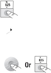
How to set controls The bottom of the screen shows control settings.
Notes:
•The ventilator will not allow the setting of values it cannot supply. A reject tone will sound or a message will appear on the screen.
•If the incorrect key is pushed, wait ten seconds or push the correct key.
•If the new setting is not saved, the ventilator continues to use the old setting.
Step 1
Push the selection key below the setting.
AB.29.010
Step 2
Turn the knob to change the setting.
Step 3
Push the knob or the key to save the change.

 AB.29.002
AB.29.011
2-14 |
1009-0632-000 |

2 System Controls and Menus
How to use the menu Screens go back to the normal display 25 seconds after the last action.
During a calibration or other procedure, the screen shows the instructions.
Step 1
Push the Menu key to see the main menu.
Step 2
Turn the knob to select an option (highlight).
Step 3
Push the knob to show the next screen.
1009-0632-000
AB29.013
AB.90.036
AB90.037
AB.90.045
2-15

Aespire 7900
Menu map Figure 2-6 shows the menu map. The table tells you about some of the options.
AB.90.036 |
SE |
AB.90.041 |
AB.90.054
AB.90.045
AB.90.063
Note: If the Alarm Settings page shows VE Auto Limits On during mechanical ventilation, the system automatically calculates alarm limits.
Figure 2-7 • Menu map
2-16 |
1009-0632-000 |

2 System Controls and Menus
More about menu functions
Menu |
Option |
Function |
||||||||
|
|
|
|
|
|
|
|
|
|
|
Main |
Cardiac Bypass |
Turns off volume and apnea alarms when these are not appropriate (e.g., during |
||||||||
|
(In Progress/No) |
heart lung bypass). |
||||||||
|
|
|
|
|
|
|
|
|
|
|
Alarm Settings |
Circuit Leak |
Turns off the alarm tone for circuit leaks. You must set the low ◊E alarm first. |
||||||||
|
(Audio On/Off) |
Select ‘Audio off’ if the circuit has a known leak (e.g., an uncuffed endotracheal |
||||||||
|
|
tube). |
||||||||
|
|
|
|
|
|
|
|
|
|
|
Setup/ |
SIMV/PSVPro Setup |
Shows additional ventilation settings for SIMV and PSVPro modes. |
||||||||
Calibration |
|
|
|
|
|
|
|
|
|
|
|
|
|
|
|
|
|
|
|
|
|
|
O2 Sensor Cal |
Shows menu for O2 sensor calibration. |
||||||||
|
|
|
|
|
|
|
|
|
|
|
|
Inspiratory Pause |
Adds an inspiratory pause time to volume control breaths. |
||||||||
|
|
|
|
|
|
|
|
|
|
|
|
Heliox mode |
Tells the ventilator if heliox is in use. |
||||||||
|
(On/Off) |
|
|
|
|
|
|
|
|
|
|
|
|
|
|
|
|
|
|
|
|
|
About Ventilator... |
Shows service level settings: software version; if facility defaults or the control |
||||||||
|
|
settings from the previous case are used when the system is first turned on; |
||||||||
|
|
altitude; and drive gas (O2 or Air). |
||||||||
|
|
|
|
|
|
|
|
|
|
|
Screen and |
Alarm Limits |
’Show’ displays alarm limits next to the data on the screen. |
||||||||
Audio |
(Show/Hide) |
|
|
|
|
|
|
|
|
|
|
|
|
|
|
|
|
|
|
||
|
|
|
|
|
|
|
|
|
|
|
|
|
|
|
|
|
|
|
|
|
|
|
|
|
Show Limits |
Hide Limits |
|||
|
|
|
|
|
|
|
|
Units of Measure |
’Show’ displays units under the data on the screen. |
||||||
(Show/Hide) |
|
|
|
|
|
|
|
|
|
|
|
|
|
|
|
|
|
|
|
|
|
|
|
|
|
|
|
|
|
|
|
Show Units |
Hide Units |
|
|
1009-0632-000 |
2-17 |
 Loading...