


 Loading...
S/5 Avance Anesthesia Machine
Technical Reference Manual

S/5 Avance
Datex-Ohmeda products have unit serial numbers with coded logic which indicates a product group code, the year of manufacture and a sequential unit number for identification.
AAA F 12345
This alpha character indicates the year of product manufacture and when the serial number was assigned;
“D” = 2000, “E” = 2001, “F” = 2002, etc. “I” and “O” are not used.
S/5 and Avance are registered trademarks of Datex-Ohmeda Inc.
Other brand names or product names used in this manual are trademarks or registered trademarks of their respective holders.
11/03 1009-0357-000
Technical Reference Manual
S/5 Avance Anesthesia Machine
This document is not to be reproduced in any manner, nor are the contents to be disclosed to anyone, without the express authorization of the product service department, Datex-Ohmeda, Ohmeda Drive, PO Box 7550, Madison, Wisconsin, 53707.
© 2003 Datex-Ohmeda Inc.
1009-0357-000 11/03 |
i |
S/5 Avance
Important
The information contained in this Technical Reference manual pertains only to those models of products which are marketed by Datex-Ohmeda as of the effective date of this manual or the latest revision thereof. This Technical Reference manual was prepared for exclusive use by Datex-Ohmeda service personnel in light of their training and experience as well as the availability to them of parts, proper tools and test equipment. Consequently, Datex-Ohmeda provides this Technical Reference manual to its customers purely as a business convenience and for the customer's general information only without warranty of the results with respect to any application of such information. Furthermore, because of the wide variety of circumstances under which maintenance and repair activities may be performed and the unique nature of each individual's own experience, capacity, and qualifications, the fact that customer has received such information from Datex-Ohmeda does not imply in anyway that Datex-Ohmeda deems said individual to be qualified to perform any such maintenance or repair service. Moreover, it should not be assumed that every acceptable test and safety procedure or method, precaution, tool, equipment or device is referred to within, or that abnormal or unusual circumstances, may not warrant or suggest different or additional procedures or requirements.
This manual is subject to periodic review, update and revision. Customers are cautioned to obtain and consult the latest revision before undertaking any service of the equipment. Comments and suggestions on this manual are invited from our customers. Send your comments and suggestions to the Manager of Technical Communications, Datex-Ohmeda, Ohmeda Drive, PO Box 7550, Madison, Wisconsin 53707.
wCAUTION Servicing of this product in accordance with this Technical Reference manual should never be undertaken in the absence of proper tools, test equipment and the most recent revision to this service manual which is clearly and thoroughly understood.
Technical Competence
The procedures described in this Technical Reference manual should be performed by trained and authorized personnel only. Maintenance should only be undertaken by competent individuals who have a general knowledge of and experience with devices of this nature. No repairs should ever be undertaken or attempted by anyone not having such qualifications.
Datex-Ohmeda strongly recommends using only genuine replacement parts, manufactured or sold by Datex-Ohmeda for all repair parts replacements.
Read completely through each step in every procedure before starting the procedure; any exceptions may result in a failure to properly and safely complete the attempted procedure.
ii |
11/03 1009-0357-000 |
Table of Contents
Important . . . . . . . . . . . . . . . . . . . . . . . . . . . . . . . . . . . . . . . . . . . . . . . . . . . . . . . . . . . . . . . . . . . . . . ii
Technical Competence . . . . . . . . . . . . . . . . . . . . . . . . . . . . . . . . . . . . . . . . . . . . . . . . . . . . . . . . . . . ii
1 Introduction
1.1 What this manual includes . . . . . . . . . . . . . . . . . . . . . . . . . . . . . . . . . . . . . . . . . . . . . . . . . . .1-2 1.2 User’s Reference manuals . . . . . . . . . . . . . . . . . . . . . . . . . . . . . . . . . . . . . . . . . . . . . . . . . . .1-2 1.3 What is an S/5 Avance anesthesia machine? . . . . . . . . . . . . . . . . . . . . . . . . . . . . . . . . . . .1-3 1.4 Anesthesia system components . . . . . . . . . . . . . . . . . . . . . . . . . . . . . . . . . . . . . . . . . . . . . .1-4 1.5 Breathing system components . . . . . . . . . . . . . . . . . . . . . . . . . . . . . . . . . . . . . . . . . . . . . . . .1-6 1.6 Display controls . . . . . . . . . . . . . . . . . . . . . . . . . . . . . . . . . . . . . . . . . . . . . . . . . . . . . . . . . . . .1-7 1.7 Anesthesia system display . . . . . . . . . . . . . . . . . . . . . . . . . . . . . . . . . . . . . . . . . . . . . . . . . . .1-8
1.7.1 Using menus . . . . . . . . . . . . . . . . . . . . . . . . . . . . . . . . . . . . . . . . . . . . . . . . . . . . . . 1-10 1.8 Symbols used in the manual or on the equipment . . . . . . . . . . . . . . . . . . . . . . . . . . . . . . 1-11
2 Theory of Operation
2.1 Electrical system . . . . . . . . . . . . . . . . . . . . . . . . . . . . . . . . . . . . . . . . . . . . . . . . . . . . . . . . . . .2-2 2.2 Power subsystem . . . . . . . . . . . . . . . . . . . . . . . . . . . . . . . . . . . . . . . . . . . . . . . . . . . . . . . . . .2-4 2.2.1 Power Controller board . . . . . . . . . . . . . . . . . . . . . . . . . . . . . . . . . . . . . . . . . . . . . . . .2-5 2.2.2 Power distribution . . . . . . . . . . . . . . . . . . . . . . . . . . . . . . . . . . . . . . . . . . . . . . . . . . . .2-6 2.3 Display Unit . . . . . . . . . . . . . . . . . . . . . . . . . . . . . . . . . . . . . . . . . . . . . . . . . . . . . . . . . . . . . . .2-8
2.4 System communications . . . . . . . . . . . . . . . . . . . . . . . . . . . . . . . . . . . . . . . . . . . . . . . . . . . .2-9 2.5 System connections . . . . . . . . . . . . . . . . . . . . . . . . . . . . . . . . . . . . . . . . . . . . . . . . . . . . . . 2-10 2.5.1 Display Unit . . . . . . . . . . . . . . . . . . . . . . . . . . . . . . . . . . . . . . . . . . . . . . . . . . . . . . . 2-10 2.5.2 Display Connector board . . . . . . . . . . . . . . . . . . . . . . . . . . . . . . . . . . . . . . . . . . . . 2-10 2.6 Power Controller and Anesthesia Control board connections . . . . . . . . . . . . . . . . . . . . . 2-11
2.7 Anesthesia Control board . . . . . . . . . . . . . . . . . . . . . . . . . . . . . . . . . . . . . . . . . . . . . . . . . . 2-12 2.8 Electronic Gas Mixer . . . . . . . . . . . . . . . . . . . . . . . . . . . . . . . . . . . . . . . . . . . . . . . . . . . . . . 2-14 2.9 Ventilator Interface board . . . . . . . . . . . . . . . . . . . . . . . . . . . . . . . . . . . . . . . . . . . . . . . . . . 2-16
1009-0357-000 11/03 |
iii |
S/5 Avance
2.10 Gas flow through the anesthesia machine . . . . . . . . . . . . . . . . . . . . . . . . . . . . . . . . . . . 2-18
2.10.1 Overview . . . . . . . . . . . . . . . . . . . . . . . . . . . . . . . . . . . . . . . . . . . . . . . . . . . . . . . . 2-18 2.10.2 Physical connections . . . . . . . . . . . . . . . . . . . . . . . . . . . . . . . . . . . . . . . . . . . . . . 2-22 2.10.3 Suction regulators . . . . . . . . . . . . . . . . . . . . . . . . . . . . . . . . . . . . . . . . . . . . . . . . 2-23 2.11 Flow through the breathing system . . . . . . . . . . . . . . . . . . . . . . . . . . . . . . . . . . . . . . . . . 2-24
2.11.1 Overview of flow paths . . . . . . . . . . . . . . . . . . . . . . . . . . . . . . . . . . . . . . . . . . . . . 2-24 2.11.2 Manual ventilation . . . . . . . . . . . . . . . . . . . . . . . . . . . . . . . . . . . . . . . . . . . . . . . . 2-25 2.11.3 Mechanical ventilation . . . . . . . . . . . . . . . . . . . . . . . . . . . . . . . . . . . . . . . . . . . . . 2-28 2.11.4 Fresh gas and O2 flush flow (with SCGO). . . . . . . . . . . . . . . . . . . . . . . . . . . . . . . 2-31 2.11.5 Fresh gas and O2 flush flow (with ACGO). . . . . . . . . . . . . . . . . . . . . . . . . . . . . . . 2-33
2.12 Ventilator mechanical subsystems . . . . . . . . . . . . . . . . . . . . . . . . . . . . . . . . . . . . . . . . . 2-35
2.12.1 Drive gas filter and Gas Inlet Valve . . . . . . . . . . . . . . . . . . . . . . . . . . . . . . . . . . . 2-35 2.12.2 Pressure regulator . . . . . . . . . . . . . . . . . . . . . . . . . . . . . . . . . . . . . . . . . . . . . . . . 2-36 2.12.3 Flow control valve . . . . . . . . . . . . . . . . . . . . . . . . . . . . . . . . . . . . . . . . . . . . . . . . . 2-36 2.12.4 Drive Gas Check Valve (DGCV) . . . . . . . . . . . . . . . . . . . . . . . . . . . . . . . . . . . . . . 2-37 2.12.5 Bellows Pressure Relief Valve . . . . . . . . . . . . . . . . . . . . . . . . . . . . . . . . . . . . . . . 2-37 2.12.6 Exhalation valve . . . . . . . . . . . . . . . . . . . . . . . . . . . . . . . . . . . . . . . . . . . . . . . . . . 2-38 2.12.7 Mechanical Overpressure Valve . . . . . . . . . . . . . . . . . . . . . . . . . . . . . . . . . . . . . 2-39 2.12.8 Reservoir and bleed resistor . . . . . . . . . . . . . . . . . . . . . . . . . . . . . . . . . . . . . . . . 2-39 2.12.9 Free breathing valve . . . . . . . . . . . . . . . . . . . . . . . . . . . . . . . . . . . . . . . . . . . . . . . 2-40 2.12.10 Breathing circuit flow sensors . . . . . . . . . . . . . . . . . . . . . . . . . . . . . . . . . . . . . . 2-40
3 Checkout Procedure
3.1 Inspect the system . . . . . . . . . . . . . . . . . . . . . . . . . . . . . . . . . . . . . . . . . . . . . . . . . . . . . . . . . |
3-2 |
3.2 System “All checks” . . . . . . . . . . . . . . . . . . . . . . . . . . . . . . . . . . . . . . . . . . . . . . . . . . . . . . . . |
3-3 |
3.2.1 Low P leak check . . . . . . . . . . . . . . . . . . . . . . . . . . . . . . . . . . . . . . . . . . . . . . . . . . . . |
3-3 |
3.2.2 Quick check . . . . . . . . . . . . . . . . . . . . . . . . . . . . . . . . . . . . . . . . . . . . . . . . . . . . . . . . . |
3-4 |
3.2.3 Vent check . . . . . . . . . . . . . . . . . . . . . . . . . . . . . . . . . . . . . . . . . . . . . . . . . . . . . . . . . . |
3-4 |
3.2.4 Circuit O2 cell check . . . . . . . . . . . . . . . . . . . . . . . . . . . . . . . . . . . . . . . . . . . . . . . . . . |
3-4 |
3.3 Backlight test . . . . . . . . . . . . . . . . . . . . . . . . . . . . . . . . . . . . . . . . . . . . . . . . . . . . . . . . . . . . . . |
3-5 |
3.4 Vaporizer back pressure test . . . . . . . . . . . . . . . . . . . . . . . . . . . . . . . . . . . . . . . . . . . . . . . . . |
3-5 |
3.5 Pipeline and cylinder tests . . . . . . . . . . . . . . . . . . . . . . . . . . . . . . . . . . . . . . . . . . . . . . . . . . . |
3-6 |
3.5.1 O2 supply alarm test . . . . . . . . . . . . . . . . . . . . . . . . . . . . . . . . . . . . . . . . . . . . . . . . . .3-6 3.6 Pressure relief tests . . . . . . . . . . . . . . . . . . . . . . . . . . . . . . . . . . . . . . . . . . . . . . . . . . . . . . . . .3-7
3.7 Flush Flow Test . . . . . . . . . . . . . . . . . . . . . . . . . . . . . . . . . . . . . . . . . . . . . . . . . . . . . . . . . . . . .3-8
3.8 Alarm tests . . . . . . . . . . . . . . . . . . . . . . . . . . . . . . . . . . . . . . . . . . . . . . . . . . . . . . . . . . . . . . . .3-9
3.9 Alternate O2 flowmeter tests . . . . . . . . . . . . . . . . . . . . . . . . . . . . . . . . . . . . . . . . . . . . . . . |
3-10 |
3.10 Auxiliary O2 flowmeter tests . . . . . . . . . . . . . . . . . . . . . . . . . . . . . . . . . . . . . . . . . . . . . . . |
3-10 |
3.11 Integrated Suction Regulator tests . . . . . . . . . . . . . . . . . . . . . . . . . . . . . . . . . . . . . . . . . |
3-10 |
3.12 Power failure test . . . . . . . . . . . . . . . . . . . . . . . . . . . . . . . . . . . . . . . . . . . . . . . . . . . . . . . |
3-11 |
3.13 Electrical safety tests . . . . . . . . . . . . . . . . . . . . . . . . . . . . . . . . . . . . . . . . . . . . . . . . . . . . |
3-11 |
iv |
11/03 1009-0357-000 |
Table of Contents
4 Installation and Service Menus
4.1 Service and Installation menu structure . . . . . . . . . . . . . . . . . . . . . . . . . . . . . . . . . . . . . . . .4-2
4.2 Install/Service Menu (Super User) . . . . . . . . . . . . . . . . . . . . . . . . . . . . . . . . . . . . . . . . . . . . .4-3
4.2.1 Colors Menu . . . . . . . . . . . . . . . . . . . . . . . . . . . . . . . . . . . . . . . . . . . . . . . . . . . . . . . .4-4
4.2.2 Units Menu . . . . . . . . . . . . . . . . . . . . . . . . . . . . . . . . . . . . . . . . . . . . . . . . . . . . . . . . .4-4
4.2.3 Factory Defaults . . . . . . . . . . . . . . . . . . . . . . . . . . . . . . . . . . . . . . . . . . . . . . . . . . . . .4-5
4.3 Installation Menu . . . . . . . . . . . . . . . . . . . . . . . . . . . . . . . . . . . . . . . . . . . . . . . . . . . . . . . . . .4-6
4.3.1 Configuration . . . . . . . . . . . . . . . . . . . . . . . . . . . . . . . . . . . . . . . . . . . . . . . . . . . . . . .4-7
4.3.2 Units Menu . . . . . . . . . . . . . . . . . . . . . . . . . . . . . . . . . . . . . . . . . . . . . . . . . . . . . . . . .4-8
4.3.3 Options Key . . . . . . . . . . . . . . . . . . . . . . . . . . . . . . . . . . . . . . . . . . . . . . . . . . . . . . . . .4-8
4.3.4 Copy Configuration . . . . . . . . . . . . . . . . . . . . . . . . . . . . . . . . . . . . . . . . . . . . . . . . . . .4-9
4.4 Service Menu . . . . . . . . . . . . . . . . . . . . . . . . . . . . . . . . . . . . . . . . . . . . . . . . . . . . . . . . . . . . 4-10
4.4.1 Software/Hardware Ver Menu . . . . . . . . . . . . . . . . . . . . . . . . . . . . . . . . . . . . . . . . 4-11
4.4.2 Service Log Menu . . . . . . . . . . . . . . . . . . . . . . . . . . . . . . . . . . . . . . . . . . . . . . . . . . 4-12
4.4.3 Calibration . . . . . . . . . . . . . . . . . . . . . . . . . . . . . . . . . . . . . . . . . . . . . . . . . . . . . . . . 4-13
4.4.4 Manifold P Span . . . . . . . . . . . . . . . . . . . . . . . . . . . . . . . . . . . . . . . . . . . . . . . . . . . 4-14
4.4.5 Insp Flow Zero . . . . . . . . . . . . . . . . . . . . . . . . . . . . . . . . . . . . . . . . . . . . . . . . . . . . . 4-15
4.4.6 Inspiratory Flow Valve . . . . . . . . . . . . . . . . . . . . . . . . . . . . . . . . . . . . . . . . . . . . . . . 4-16
4.4.7 Bleed Resistor . . . . . . . . . . . . . . . . . . . . . . . . . . . . . . . . . . . . . . . . . . . . . . . . . . . . . 4-18
4.4.8 Paw Span . . . . . . . . . . . . . . . . . . . . . . . . . . . . . . . . . . . . . . . . . . . . . . . . . . . . . . . . 4-19
4.4.9 Zero Gas Xducer . . . . . . . . . . . . . . . . . . . . . . . . . . . . . . . . . . . . . . . . . . . . . . . . . . . 4-20
4.4.10 Cal Config . . . . . . . . . . . . . . . . . . . . . . . . . . . . . . . . . . . . . . . . . . . . . . . . . . . . . . . 4-21
5 Calibration
5.1 Primary Regulators . . . . . . . . . . . . . . . . . . . . . . . . . . . . . . . . . . . . . . . . . . . . . . . . . . . . . . . |
. .5-2 |
5.1.1 Test setup . . . . . . . . . . . . . . . . . . . . . . . . . . . . . . . . . . . . . . . . . . . . . . . . . . . . . . . . |
. .5-3 |
5.1.2 Testing Primary Regulators . . . . . . . . . . . . . . . . . . . . . . . . . . . . . . . . . . . . . . . . . . |
. .5-3 |
5.1.3 Adjusting Primary Regulators . . . . . . . . . . . . . . . . . . . . . . . . . . . . . . . . . . . . . . . . . . |
.5-8 |
5.2 O2 Flush Regulator . . . . . . . . . . . . . . . . . . . . . . . . . . . . . . . . . . . . . . . . . . . . . . . . . . . . . . . . |
.5-9 |
5.3 Adjust Drive Gas Regulator . . . . . . . . . . . . . . . . . . . . . . . . . . . . . . . . . . . . . . . . . . . . . . . . . |
5-10 |
5.4 Ventilator Calibrations . . . . . . . . . . . . . . . . . . . . . . . . . . . . . . . . . . . . . . . . . . . . . . . . . . . . |
5-11 |
5.4.1 Cal Config . . . . . . . . . . . . . . . . . . . . . . . . . . . . . . . . . . . . . . . . . . . . . . . . . . . . . . . . 5-11
5.4.2 Manifold P Span . . . . . . . . . . . . . . . . . . . . . . . . . . . . . . . . . . . . . . . . . . . . . . . . . . . 5-12
5.4.3 Insp Flow Zero . . . . . . . . . . . . . . . . . . . . . . . . . . . . . . . . . . . . . . . . . . . . . . . . . . . . . 5-12
5.4.4 Inspiratory Flow Valve Cal . . . . . . . . . . . . . . . . . . . . . . . . . . . . . . . . . . . . . . . . . . . . 5-13
5.4.5 Bleed Resistor Cal . . . . . . . . . . . . . . . . . . . . . . . . . . . . . . . . . . . . . . . . . . . . . . . . . . 5-13
5.4.6 Paw Span . . . . . . . . . . . . . . . . . . . . . . . . . . . . . . . . . . . . . . . . . . . . . . . . . . . . . . . . . 5-14
1009-0357-000 11/03 |
v |
S/5 Avance
6 Maintenance
6.1 S/5 Avance Planned Maintenance . . . . . . . . . . . . . . . . . . . . . . . . . . . . . . . . . . . . . . . . . . |
. .6-2 |
6.1.1 Every twelve (12) months . . . . . . . . . . . . . . . . . . . . . . . . . . . . . . . . . . . . . . . . . . . . . |
.6-2 |
6.1.2 Every twenty-four (24) months . . . . . . . . . . . . . . . . . . . . . . . . . . . . . . . . . . . . . . . . |
.6-3 |
6.1.3 Every forty-eight (48) months . . . . . . . . . . . . . . . . . . . . . . . . . . . . . . . . . . . . . . . . . |
.6-3 |
6.2 Free breathing valve maintenance . . . . . . . . . . . . . . . . . . . . . . . . . . . . . . . . . . . . . . . . . . . . |
.6-4 |
6.3 MOPV pressure relief valve test . . . . . . . . . . . . . . . . . . . . . . . . . . . . . . . . . . . . . . . . . . . . . . |
.6-5 |
6.3.1 Test setup . . . . . . . . . . . . . . . . . . . . . . . . . . . . . . . . . . . . . . . . . . . . . . . . . . . . . . . . . |
.6-5 |
6.3.2 Test procedure . . . . . . . . . . . . . . . . . . . . . . . . . . . . . . . . . . . . . . . . . . . . . . . . . . . . . |
.6-5 |
6.4 Pressure Limit Circuit test . . . . . . . . . . . . . . . . . . . . . . . . . . . . . . . . . . . . . . . . . . . . . . . . . . . |
.6-6 |
6.5 Mixer test . . . . . . . . . . . . . . . . . . . . . . . . . . . . . . . . . . . . . . . . . . . . . . . . . . . . . . . . . . . . . . . . |
.6-8 |
6.5.1 Mixer outlet check valve leak test . . . . . . . . . . . . . . . . . . . . . . . . . . . . . . . . . . . . . . |
.6-8 |
6.5.2 Mixer flow verification . . . . . . . . . . . . . . . . . . . . . . . . . . . . . . . . . . . . . . . . . . . . . . . . |
.6-8 |
6.6 Alternate O2 flowmeter tests . . . . . . . . . . . . . . . . . . . . . . . . . . . . . . . . . . . . . . . . . . . . . . . . |
.6-9 |
6.7 Auxiliary O2 flowmeter tests . . . . . . . . . . . . . . . . . . . . . . . . . . . . . . . . . . . . . . . . . . . . . . . . |
6-10 |
6.8 Integrated Suction Regulator tests . . . . . . . . . . . . . . . . . . . . . . . . . . . . . . . . . . . . . . . . . . |
6-11 |
6.9 Battery capacity test . . . . . . . . . . . . . . . . . . . . . . . . . . . . . . . . . . . . . . . . . . . . . . . . . . . . . . |
6-13 |
7 Troubleshooting
7.1 General Troubleshooting . . . . . . . . . . . . . . . . . . . . . . . . . . . . . . . . . . . . . . . . . . . . . . . . . . . . .7-2
7.2 Breathing System Leak Test Guide . . . . . . . . . . . . . . . . . . . . . . . . . . . . . . . . . . . . . . . . . . . . .7-4
7.2.1 Check Valves . . . . . . . . . . . . . . . . . . . . . . . . . . . . . . . . . . . . . . . . . . . . . . . . . . . . . . . .7-5
7.2.2 Breathing System Troubleshooting Flowcharts . . . . . . . . . . . . . . . . . . . . . . . . . . . .7-6
7.2.3 Leak Isolation Tests . . . . . . . . . . . . . . . . . . . . . . . . . . . . . . . . . . . . . . . . . . . . . . . . 7-11
7.3 Technical Alarms . . . . . . . . . . . . . . . . . . . . . . . . . . . . . . . . . . . . . . . . . . . . . . . . . . . . . . . . . 7-26
7.4 Steps and Messages displayed during the System Checkout: . . . . . . . . . . . . . . . . . . . . 7-45
7.4.1 Steps for the Quick Check . . . . . . . . . . . . . . . . . . . . . . . . . . . . . . . . . . . . . . . . . . . 7-45 7.4.2 Steps for the Vent Check . . . . . . . . . . . . . . . . . . . . . . . . . . . . . . . . . . . . . . . . . . . . 7-47
8 Service Diagnostics and Software Download
8.1 Avance Service Application . . . . . . . . . . . . . . . . . . . . . . . . . . . . . . . . . . . . . . . . . . . . . . . . . .8-2
8.1.1 Main Menu and System Information . . . . . . . . . . . . . . . . . . . . . . . . . . . . . . . . . . . . .8-2 8.1.2 Power Diagnostics . . . . . . . . . . . . . . . . . . . . . . . . . . . . . . . . . . . . . . . . . . . . . . . . . . .8-3 8.1.3 Power Controller Power Diagnostics . . . . . . . . . . . . . . . . . . . . . . . . . . . . . . . . . . . . .8-4 8.1.4 Anesthesia Control Board Power Diagnostics . . . . . . . . . . . . . . . . . . . . . . . . . . . . .8-6 8.1.5 Electronic Mixer Power Diagnostics . . . . . . . . . . . . . . . . . . . . . . . . . . . . . . . . . . . . . .8-8 8.1.6 Ventilator Interface Board Power Diagnostics . . . . . . . . . . . . . . . . . . . . . . . . . . . . .8-9 8.1.7 Display Unit Power Diagnostics . . . . . . . . . . . . . . . . . . . . . . . . . . . . . . . . . . . . . . . 8-10
vi |
11/03 1009-0357-000 |
Table of Contents
8.2 Gas Diagnostics . . . . . . . . . . . . . . . . . . . . . . . . . . . . . . . . . . . . . . . . . . . . . . . . . . . . . . . . . . 8-11
8.2.1 Gas Supplies . . . . . . . . . . . . . . . . . . . . . . . . . . . . . . . . . . . . . . . . . . . . . . . . . . . . . . 8-12 8.2.2 Mixer Output . . . . . . . . . . . . . . . . . . . . . . . . . . . . . . . . . . . . . . . . . . . . . . . . . . . . . . 8-13 8.2.3 Mixer Tests and Pressure . . . . . . . . . . . . . . . . . . . . . . . . . . . . . . . . . . . . . . . . . . . . 8-14 8.2.4 Mixer Temperature . . . . . . . . . . . . . . . . . . . . . . . . . . . . . . . . . . . . . . . . . . . . . . . . . 8-15 8.2.5 Setting Gas Flow . . . . . . . . . . . . . . . . . . . . . . . . . . . . . . . . . . . . . . . . . . . . . . . . . . . 8-16 8.2.6 Breathing System Leak Test . . . . . . . . . . . . . . . . . . . . . . . . . . . . . . . . . . . . . . . . . . 8-17
8.3 Ventilation Diagnostics . . . . . . . . . . . . . . . . . . . . . . . . . . . . . . . . . . . . . . . . . . . . . . . . . . . . 8-18
8.3.1 Status . . . . . . . . . . . . . . . . . . . . . . . . . . . . . . . . . . . . . . . . . . . . . . . . . . . . . . . . . . . |
8-19 |
8.3.2 Vent Flow and Pressure . . . . . . . . . . . . . . . . . . . . . . . . . . . . . . . . . . . . . . . . . . . . . |
8-20 |
8.4 Display Diagnostics . . . . . . . . . . . . . . . . . . . . . . . . . . . . . . . . . . . . . . . . . . . . . . . . . . . . . . . |
8-21 |
8.5 Special Functions . . . . . . . . . . . . . . . . . . . . . . . . . . . . . . . . . . . . . . . . . . . . . . . . . . . . . . . . |
8-22 |
8.5.1 Mixer Service Menu . . . . . . . . . . . . . . . . . . . . . . . . . . . . . . . . . . . . . . . . . . . . . . . . |
8-23 |
8.5.2 View Revision Log . . . . . . . . . . . . . . . . . . . . . . . . . . . . . . . . . . . . . . . . . . . . . . . . . . |
8-24 |
8.5.3 View PC Card Install Log . . . . . . . . . . . . . . . . . . . . . . . . . . . . . . . . . . . . . . . . . . . . . |
8-24 |
8.6 Software Download . . . . . . . . . . . . . . . . . . . . . . . . . . . . . . . . . . . . . . . . . . . . . . . . . . . . . . . |
8-25 |
9 Repair Procedures
9.1 How to bleed gas pressure from the machine . . . . . . . . . . . . . . . . . . . . . . . . . . . . . . . . . . . .9-3
9.2 How to remove the rear panels . . . . . . . . . . . . . . . . . . . . . . . . . . . . . . . . . . . . . . . . . . . . . . . .9-4
9.2.1 To remove the rear upper panel . . . . . . . . . . . . . . . . . . . . . . . . . . . . . . . . . . . . . . . . .9-4 9.2.2 To remove the lower access panels . . . . . . . . . . . . . . . . . . . . . . . . . . . . . . . . . . . . . .9-4 9.3 How to remove the tabletop . . . . . . . . . . . . . . . . . . . . . . . . . . . . . . . . . . . . . . . . . . . . . . . . . .9-5
9.4 Servicing the Display Unit . . . . . . . . . . . . . . . . . . . . . . . . . . . . . . . . . . . . . . . . . . . . . . . . . . . .9-6
9.4.1 Remove the Display Unit . . . . . . . . . . . . . . . . . . . . . . . . . . . . . . . . . . . . . . . . . . . . |
. .9-6 |
9.4.2 Disassemble the Display Unit . . . . . . . . . . . . . . . . . . . . . . . . . . . . . . . . . . . . . . . . . |
.9-7 |
9.4.3 To replace the CPU board . . . . . . . . . . . . . . . . . . . . . . . . . . . . . . . . . . . . . . . . . . . . |
.9-8 |
9.4.4 To replace the LCD display . . . . . . . . . . . . . . . . . . . . . . . . . . . . . . . . . . . . . . . . . . . . |
.9-9 |
9.4.5 To replace the backlights . . . . . . . . . . . . . . . . . . . . . . . . . . . . . . . . . . . . . . . . . . . . |
9-10 |
9.4.6 To replace the Inverters . . . . . . . . . . . . . . . . . . . . . . . . . . . . . . . . . . . . . . . . . . . . . |
9-11 |
9.4.7 To replace the front enclosure or components . . . . . . . . . . . . . . . . . . . . . . . . . . . |
9-12 |
9.5 Replacing the Display and MGAS cables . . . . . . . . . . . . . . . . . . . . . . . . . . . . . . . . . . . . . |
9-14 |
9.5.1 Remove the MGAS oxygen partition . . . . . . . . . . . . . . . . . . . . . . . . . . . . . . . . . . . |
9-14 |
9.6 Servicing the lower electrical enclosure components . . . . . . . . . . . . . . . . . . . . . . . . . . . |
9-15 |
9.6.1 Power Controller board . . . . . . . . . . . . . . . . . . . . . . . . . . . . . . . . . . . . . . . . . . . . . . |
9-15 |
9.6.2 Anesthesia Control board . . . . . . . . . . . . . . . . . . . . . . . . . . . . . . . . . . . . . . . . . . . |
9-16 |
9.6.3 Backup batteries . . . . . . . . . . . . . . . . . . . . . . . . . . . . . . . . . . . . . . . . . . . . . . . . . . |
9-17 |
9.6.4 Fan . . . . . . . . . . . . . . . . . . . . . . . . . . . . . . . . . . . . . . . . . . . . . . . . . . . . . . . . . . . . . . |
9-18 |
9.6.5 Display Connector board . . . . . . . . . . . . . . . . . . . . . . . . . . . . . . . . . . . . . . . . . . . . |
9-18 |
1009-0357-000 11/03 |
vii |
S/5 Avance
9.7 Servicing the pan electrical enclosure components . . . . . . . . . . . . . . . . . . . . . . . . . . . . . 9-19
9.7.1 Electronic Gas Mixer assembly . . . . . . . . . . . . . . . . . . . . . . . . . . . . . . . . . . . . . . . 9-19 9.7.2 Ventilator Interface board . . . . . . . . . . . . . . . . . . . . . . . . . . . . . . . . . . . . . . . . . . . 9-20 9.7.3 Filter board . . . . . . . . . . . . . . . . . . . . . . . . . . . . . . . . . . . . . . . . . . . . . . . . . . . . . . . 9-21 9.7.4 Pan Connector board . . . . . . . . . . . . . . . . . . . . . . . . . . . . . . . . . . . . . . . . . . . . . . . 9-22 9.7.5 Pan enclosure fan . . . . . . . . . . . . . . . . . . . . . . . . . . . . . . . . . . . . . . . . . . . . . . . . . . 9-22
9.8 Servicing the Vent Engine . . . . . . . . . . . . . . . . . . . . . . . . . . . . . . . . . . . . . . . . . . . . . . . . . . 9-23
9.8.1 To remove the Vent Engine . . . . . . . . . . . . . . . . . . . . . . . . . . . . . . . . . . . . . . . . . . . 9-24 9.8.2 Replacing Vent Engine components . . . . . . . . . . . . . . . . . . . . . . . . . . . . . . . . . . . 9-25 9.8.3 Replacing GIV components . . . . . . . . . . . . . . . . . . . . . . . . . . . . . . . . . . . . . . . . . . 9-26 9.9 Servicing the pipeline inlet manifold components . . . . . . . . . . . . . . . . . . . . . . . . . . . . . . 9-27
9.9.1 Replace pipeline inlet filter . . . . . . . . . . . . . . . . . . . . . . . . . . . . . . . . . . . . . . . . . . 9-27 9.9.2 Replace pipeline inlet check valve . . . . . . . . . . . . . . . . . . . . . . . . . . . . . . . . . . . . 9-27 9.9.3 Replace the inlet manifold . . . . . . . . . . . . . . . . . . . . . . . . . . . . . . . . . . . . . . . . . . . 9-28 9.10 Service the cylinder supply modules . . . . . . . . . . . . . . . . . . . . . . . . . . . . . . . . . . . . . . . . 9-29
9.10.1 Replace primary regulator module (complete replacement) . . . . . . . . . . . . . . 9-29 9.10.2 Replace cylinder inlet filter . . . . . . . . . . . . . . . . . . . . . . . . . . . . . . . . . . . . . . . . . 9-30 9.10.3 Replace cylinder check valve . . . . . . . . . . . . . . . . . . . . . . . . . . . . . . . . . . . . . . . 9-30 9.11 Replace gas-supply pressure transducers . . . . . . . . . . . . . . . . . . . . . . . . . . . . . . . . . . . 9-31
9.12 Service vaporizer manifold parts . . . . . . . . . . . . . . . . . . . . . . . . . . . . . . . . . . . . . . . . . . . |
9-32 |
9.12.1 Repair manifold port valve . . . . . . . . . . . . . . . . . . . . . . . . . . . . . . . . . . . . . . . . . |
9-32 |
9.12.2 Checkout procedure for manifold port valve . . . . . . . . . . . . . . . . . . . . . . . . . . . |
9-33 |
9.12.3 Replace vaporizer manifold check valve . . . . . . . . . . . . . . . . . . . . . . . . . . . . . . |
9-34 |
9.12.4 Replace vaporizer pressure relief valve . . . . . . . . . . . . . . . . . . . . . . . . . . . . . . . |
9-36 |
9.12.5 Replace vaporizer manifold . . . . . . . . . . . . . . . . . . . . . . . . . . . . . . . . . . . . . . . . . |
9-37 |
9.13 Clean or replace ACGO port flapper valve . . . . . . . . . . . . . . . . . . . . . . . . . . . . . . . . . . . . |
9-38 |
9.14 Replace the APL valve . . . . . . . . . . . . . . . . . . . . . . . . . . . . . . . . . . . . . . . . . . . . . . . . . . . |
9-39 |
9.15 Replace the bag support arm . . . . . . . . . . . . . . . . . . . . . . . . . . . . . . . . . . . . . . . . . . . . . . |
9-40 |
9.15.1 Servicing the bag support arm . . . . . . . . . . . . . . . . . . . . . . . . . . . . . . . . . . . . . . |
9-41 |
9.16 Replace system switch assembly . . . . . . . . . . . . . . . . . . . . . . . . . . . . . . . . . . . . . . . . . . |
9-42 |
9.17 Replace Alt O2 components . . . . . . . . . . . . . . . . . . . . . . . . . . . . . . . . . . . . . . . . . . . . . . |
9-44 |
9.18 Replace auxiliary O2 flowmeter . . . . . . . . . . . . . . . . . . . . . . . . . . . . . . . . . . . . . . . . . . . . |
9-45 |
9.19 Replace the suction regulator . . . . . . . . . . . . . . . . . . . . . . . . . . . . . . . . . . . . . . . . . . . . . |
9-46 |
9.20 Replace task light components . . . . . . . . . . . . . . . . . . . . . . . . . . . . . . . . . . . . . . . . . . . . |
9-47 |
9.20.1 To replace the task light switch . . . . . . . . . . . . . . . . . . . . . . . . . . . . . . . . . . . . . . 9-47 9.20.2 To replace the upper task light . . . . . . . . . . . . . . . . . . . . . . . . . . . . . . . . . . . . . . 9-47 9.20.3 To replace the lower task light . . . . . . . . . . . . . . . . . . . . . . . . . . . . . . . . . . . . . . . 9-48
viii |
11/03 1009-0357-000 |
Table of Contents
9.21 Replace ABS breathing system components . . . . . . . . . . . . . . . . . . . . . . . . . . . . . . . . . 9-49
9.21.1 Replace Bag/Vent switch assembly . . . . . . . . . . . . . . . . . . . . . . . . . . . . . . . . . . 9-49 9.21.2 Replace bellows base latch assembly . . . . . . . . . . . . . . . . . . . . . . . . . . . . . . . . 9-50 9.22 Replace casters . . . . . . . . . . . . . . . . . . . . . . . . . . . . . . . . . . . . . . . . . . . . . . . . . . . . . . . . . 9-51
9.23 Reconfigure sample gas return line . . . . . . . . . . . . . . . . . . . . . . . . . . . . . . . . . . . . . . . . . 9-52
9.24 Change drive gas . . . . . . . . . . . . . . . . . . . . . . . . . . . . . . . . . . . . . . . . . . . . . . . . . . . . . . . . 9-53
10 Illustrated Parts
10.1 Service tools . . . . . . . . . . . . . . . . . . . . . . . . . . . . . . . . . . . . . . . . . . . . . . . . . . . . . . . . . . . |
10-3 |
10.1.1 Software tools . . . . . . . . . . . . . . . . . . . . . . . . . . . . . . . . . . . . . . . . . . . . . . . . . . . . 10-3 10.1.2 Manifold pressure test adapter . . . . . . . . . . . . . . . . . . . . . . . . . . . . . . . . . . . . . . 10-3 10.1.3 Test Devices. . . . . . . . . . . . . . . . . . . . . . . . . . . . . . . . . . . . . . . . . . . . . . . . . . . . . . 10-4 10.1.4 Lubricants and Adhesives . . . . . . . . . . . . . . . . . . . . . . . . . . . . . . . . . . . . . . . . . . 10-4 10.1.5 Test Tools . . . . . . . . . . . . . . . . . . . . . . . . . . . . . . . . . . . . . . . . . . . . . . . . . . . . . . . . 10-5
10.2 External components - front view . . . . . . . . . . . . . . . . . . . . . . . . . . . . . . . . . . . . . . . . . . . 10-6
10.3 External components - front view references . . . . . . . . . . . . . . . . . . . . . . . . . . . . . . . . . 10-7
10.4 External Components - rear view . . . . . . . . . . . . . . . . . . . . . . . . . . . . . . . . . . . . . . . . . . . |
10-8 |
10.5 AC Power cords and AC Inlet filter . . . . . . . . . . . . . . . . . . . . . . . . . . . . . . . . . . . . . . . . . . |
10-9 |
10.6 AC Inlet/Outlet Components . . . . . . . . . . . . . . . . . . . . . . . . . . . . . . . . . . . . . . . . . . . . . 10-10
10.7 Display Unit . . . . . . . . . . . . . . . . . . . . . . . . . . . . . . . . . . . . . . . . . . . . . . . . . . . . . . . . . . . 10-12
10.8 Lower electronic enclosure components . . . . . . . . . . . . . . . . . . . . . . . . . . . . . . . . . . . . 10-14
10.9 Pan electronic enclosure components . . . . . . . . . . . . . . . . . . . . . . . . . . . . . . . . . . . . . 10-15
10.10 Electronic Gas Mixer . . . . . . . . . . . . . . . . . . . . . . . . . . . . . . . . . . . . . . . . . . . . . . . . . . . 10-16
10.11 Pipeline inlet fittings . . . . . . . . . . . . . . . . . . . . . . . . . . . . . . . . . . . . . . . . . . . . . . . . . . . 10-17
10.12 Cylinder Gas Supplies . . . . . . . . . . . . . . . . . . . . . . . . . . . . . . . . . . . . . . . . . . . . . . . . . 10-18
10.12.1 Cylinder inlet fittings. . . . . . . . . . . . . . . . . . . . . . . . . . . . . . . . . . . . . . . . . . . . . 10-19
10.13 Vaporizer manifold . . . . . . . . . . . . . . . . . . . . . . . . . . . . . . . . . . . . . . . . . . . . . . . . . . . . 10-20
10.14 Vent Engine Housing . . . . . . . . . . . . . . . . . . . . . . . . . . . . . . . . . . . . . . . . . . . . . . . . . . |
10-21 |
10.15 Vent Engine . . . . . . . . . . . . . . . . . . . . . . . . . . . . . . . . . . . . . . . . . . . . . . . . . . . . . . . . . . |
10-22 |
10.15.1 Vent Engine - under side . . . . . . . . . . . . . . . . . . . . . . . . . . . . . . . . . . . . . . . . . |
10-23 |
10.16 ABS to machine Interface Components (SCGO) . . . . . . . . . . . . . . . . . . . . . . . . . . . . |
10-24 |
10.17 ABS to machine Interface Components (ACGO) . . . . . . . . . . . . . . . . . . . . . . . . . . . . |
10-25 |
10.18 Flush Regulator and Flush Valve . . . . . . . . . . . . . . . . . . . . . . . . . . . . . . . . . . . . . . . . . |
10-26 |
10.19 Front panel, Alt O2, and system switch . . . . . . . . . . . . . . . . . . . . . . . . . . . . . . . . . . . . 10-27
10.20 Breathing system interface . . . . . . . . . . . . . . . . . . . . . . . . . . . . . . . . . . . . . . . . . . . . . 10-28
1009-0357-000 11/03 |
ix |
S/5 Avance
10.21Breathing System 10-29
10.21.1APL Valve 10-29
10.21.2Bag/Vent Switch 10-30
10.21.3Absorber canister 10-31
10.21.4Flow Sensor Module 10-32
10.21.5Breathing Circuit Module 10-33
10.21.6Exhalation valve 10-34
10.21.7Bellows 10-35
10.21.8Bellow base 10-36
10.21.9Bag Arms 10-37
10.22Anesthetic Gas Scavenging System — AGSS 10-38
10.22.1Passive AGSS 10-38
10.22.2Adjustable AGSS 10-40
10.22.3Active AGSS 10-42
10.23AGSS gauge, and sample return 10-44
10.23.1Airway module (MGAS) components 10-45
10.24Integrated Suction Regulator 10-46
10.24.1Major Components (Continuous and Venturi suction) 10-46
10.24.2Suction Control Module 10-47
10.24.3Venturi assembly 10-48
10.25Auxiliary O2 Flowmeter 10-49
10.26Rear panel components 10-50
10.27Tabletop components 10-51
10.28Right-side Components 10-52
10.29External components - lower assembly 10-53
10.30Drawer 10-54
10.31Fittings and tubing charts 10-55
10.31.1Legris quick-release fittings 10-55
10.32Vent Drive and low-pressure tubing 10-56
10.33Tubing for use with Legris fittings 10-58
10.34Cables and harnesses 10-60
10.35Cables and harnesses in lower electronic enclosure 10-62
10.36Cables and harnesses in Pan enclosure 10-64
11 Schematics and Diagrams
x |
11/03 1009-0357-000 |
1 Introduction
In this section This section provides a general overview of the S/5 Avance anesthesia machine.
1.1 What this manual includes . . . . . . . . . . . . . . . . . . . . . . . . . . . . . . . . . . . . . . . . . . . . . . . . . . .1-2 1.2 User’s Reference manuals . . . . . . . . . . . . . . . . . . . . . . . . . . . . . . . . . . . . . . . . . . . . . . . . . . .1-2 1.3 What is an S/5 Avance anesthesia machine? . . . . . . . . . . . . . . . . . . . . . . . . . . . . . . . . . . .1-3 1.4 Anesthesia system components . . . . . . . . . . . . . . . . . . . . . . . . . . . . . . . . . . . . . . . . . . . . . .1-4 1.5 Breathing system components . . . . . . . . . . . . . . . . . . . . . . . . . . . . . . . . . . . . . . . . . . . . . . . .1-6 1.6 Display controls . . . . . . . . . . . . . . . . . . . . . . . . . . . . . . . . . . . . . . . . . . . . . . . . . . . . . . . . . . . .1-7 1.7 Anesthesia system display . . . . . . . . . . . . . . . . . . . . . . . . . . . . . . . . . . . . . . . . . . . . . . . . . . .1-8
1.7.1 Using menus . . . . . . . . . . . . . . . . . . . . . . . . . . . . . . . . . . . . . . . . . . . . . . . . . . . . . . 1-10 1.8 Symbols used in the manual or on the equipment . . . . . . . . . . . . . . . . . . . . . . . . . . . . . . 1-11
1009-0357-000 11/03 |
1-1 |
S/5 Avance
1.1 What this manual includes
This manual covers the service information for the S/5 Avance line of anesthesia machines. It covers the following components:
•Display Unit
•Integral electronics
•Gas delivery components
•Breathing system components
•Frame component
•Optional suction regulator
•Optional auxiliary O2 flowmeter
Other equipment Other equipment may be attached to the system on a display mount, the top shelf, or on the side dovetail rails. Consult separate documentation relative to these items for details.
1.2 User’s Reference manuals
Some sections of this manual refer you to the User’s Reference manual for the
S/5 Avance. To expedite repairs, you must have, and be familiar with, the
User’s Reference manuals for this product.
Refer to the S/5 Avance User’s Reference manual if you need further information about the operation of the system.
1-2 |
11/03 1009-0357-000 |

1 Introduction
1.3 What is an S/5 Avance anesthesia machine?
The S/5 Avance anesthesia machine is a compact, integrated, and intuitive anesthesia delivery system. It provides electronic gas mixing and optional integrated respiratory gas monitoring.
AB.91.024
Figure 1-1 • S/5 Avance system
1009-0357-000 11/03 |
1-3 |

S/5 Avance
1.4 Anesthesia system components
1
8
7
6
1.Anesthesia system display
2.Dovetail rails
3.Vaporizer
4.Alternate O2
5.System switch
6.Brake
7.O2 flush button
8.Breathing system
Figure 1-2 • Front view
2
3
4
5
AB.91.028
1-4 |
11/03 1009-0357-000 |
1 Introduction
1
2
7
3
AB.43.085
6
5
4
1.Outlet Circuit breaker (optional)
2.Electrical outlet (optional)
3.Cylinders supplies
4.Equipotential stud
5.Mains inlet
6.System circuit breaker
7.Pipeline connections
Figure 1-3 • Rear view
1009-0357-000 11/03 |
1-5 |
S/5 Avance
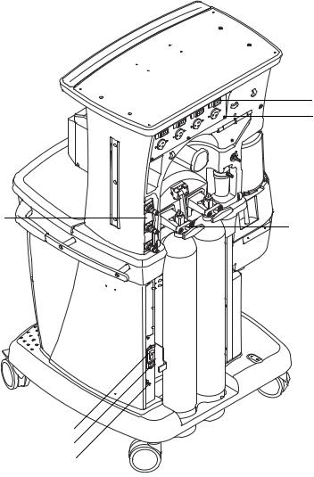
1.5 Breathing system components
15
14
13
12
11
10
AB.91.023 |
16 |
|
|
|
1 |
|
2 |
|
AB.91.045 |
9
8
3
5 4
6
7
1.Expiratory check valve
2.Inspiratory check valve
3.ACGO (optional)
4.Inspiratory flow sensor
5.Expiratory flow sensor
6.Absorber canister
7.Absorber canister release
8.Leak test plug
9.Breathing system release
10.Manual bag port
11.Adjustable pressure-limiting (APL) valve
12.Bag/mechanical ventilation switch
13.Bellows assembly
14.Sample gas return port
15.AGSS indicator (only available on some AGSS versions)
16.Bag support arm (optional)
Figure 1-4 • Breathing system
1-6 |
11/03 1009-0357-000 |
1 Introduction
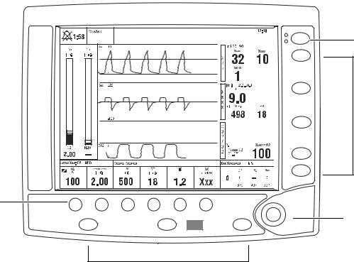
1.6 Display controls
|
|
Silence |
1 |
|
|
Alarms |
|
|
|
|
|
|
|
Alarms |
|
|
|
Setup |
|
|
|
Help |
|
|
|
Main |
2 |
|
|
Menu |
|
|
|
Checkout |
|
|
|
Start/End |
|
|
|
Case |
|
4 |
|
|
AB.91.073 |
Gas Setup |
Vent Setup |
Normal |
3 |
Screen |
|
||
|
|
|
|
|
2 |
|
|
Item |
|
Description |
|
|
|
1 |
Alarm silence key |
Push to silence any active, silenceable high and medium |
|
|
priority alarms. Alarm is silenced for 120 seconds. |
|
|
|
2 |
Menu keys |
Push to show corresponding menu. |
|
|
|
3 |
ComWheel |
Push to select a menu item or confirm a setting. Turn right |
|
|
or left to scroll menu items or change settings. |
|
|
|
4 |
Quick keys |
Push to change corresponding gas setting or vent setting. |
|
|
Use the ComWheel to make a change. Push the ComWheel |
|
|
to activate the change. |
|
|
|
Figure 1-5 • Ventilator controls
1009-0357-000 11/03 |
1-7 |
S/5 Avance
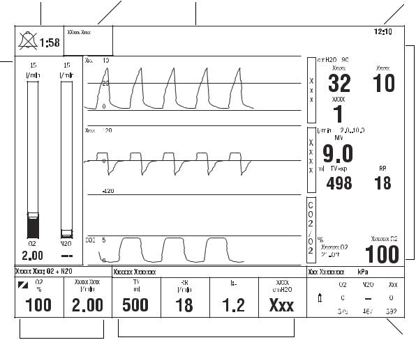
1.7 Anesthesia system display
2 |
3 |
4 |
5 |
1 |
|
|
|
|
|
|
6 |
|
|
|
AB.91.002 |
9 |
|
8 |
7 |
1.Electronic gas flow tubes
2.Alarm silence countdown
3.Alarm message fields
4.Waveform field
5.Clock
6.Number field
7.Free number display
8.Ventilator settings
9.Gas settings
Figure 1-6 • Normal view
1-8 |
11/03 1009-0357-000 |
1 Introduction
When a menu key is selected, the menu field overlays the gas flow tubes and the waveform fields start at the right edge of the menu.
2 |
1 |
AB.91.003 |
1.Menu
2.Waveform fields
Figure 1-7 • Menu view
1009-0357-000 11/03 |
1-9 |

Notes
1.7.1 Using menus
Push a menu key to display the corresponding menu. Use the ComWheel to navigate through the menu.
|
1 |
|
2 |
|
3 |
6 |
|
|
4 |
|
Xxxxxx Xxxxxx |
5 |
AB.91.007 |
|
1.Menu title
2.Present selection
3.Adjustment window
4.Indicates submenu
5.Short instructions
6.Menu selections
Figure 1-8 • Example menu
1.Push the menu key to display the corresponding menu.
2.Turn the ComWheel counterclockwise to highlight the next menu item. (Turn the ComWheel clockwise to highlight the previous menu item.)
3.Push the ComWheel to enter the adjustment window or a submenu.
4.Turn the ComWheel clockwise or counterclockwise to highlight the desired selection.
5.Push the ComWheel to confirm the selection.
6.Select Normal Screen or push the Normal Screen key to exit the menu and return to the normal monitoring display. (Select Previous Menu to return to the last displayed menu, if available.)
1-10 |
11/03 1009-0357-000 |

1 Introduction
1.8 Symbols used in the manual or on the equipment
wWarnings and wCautions tell you about dangerous conditions that can occur if you do not follow all instructions in this manual.
Warnings tell about a condition that can cause injury to the operator or the patient.
Cautions tell about a condition that can cause damage to the equipment. Read and follow all warnings and cautions.
Other symbols replace words on the equipment or in Datex-Ohmeda manuals. No one device or manual uses all of the symbols. These symbols include:
m
L l
n
M N
†
On (power)
Off (power)
Standby
Standby or preparatory state for part of the equipment
“ON” only for part of the equipment
“OFF” only for part of the equipment
Direct current
A Alarm silence button
|
Alarm silence touch key (Tec 6). |
j |
Type B equipment |
J |
Type BF equipment |
D |
Type CF equipment |
wCaution, ISO 7000-0434
wW |
Attention, refer to product instructions, |
IEC 60601-1 |
p x
y
P
Y
Alternating current
Protective earth ground
Earth ground
Frame or chassis ground
Equipotential
O |
Dangerous voltage |
|
Electrical input |
|
Electrical output |
|
Pneumatic input |
|
Pneumatic output |
1009-0357-000 11/03 |
1-11 |
S/5 Avance
+
-
t
T g
o
z
Z
U
u
134°C
Í
q t
REF
Plus, positive polarity
Minus, negative polarity
Variability
Variability in steps
This way up
Lamp, lighting, illumination
Lock
Unlock
Close drain
Open drain (remove liquid)
Autoclavable
Not autoclavable
Inspiratory flow
O2 sensor connection Stock Number
k |
Movement in one direction |
E Movement in two directions |
|
|
Read top of float |
|
Vacuum inlet |
|
Suction bottle outlet |
|
Cylinder |
|
Isolation transformer |
|
Linkage system |
|
Risk of Explosion. |
|
Low pressure leak test |
r |
Mechanical ventilation |
R |
Bag position/ manual ventilation |
Q |
Expiratory flow |
O2+ |
O2 Flush button |
SN |
Serial Number |
|
1-12 |
11/03 1009-0357-000 |
1 Introduction
Alarm silence touch key |
Volume alarms On/Off touch key |
End case touch key |
Menu touch key |
|
Circle breathing circuit module |
|
Bain/Mapleson D breathing circuit |
|
|
|
|
module |
|
< 345 kPa |
The primary regulator is set to pressure |
< 414 kPa |
The primary regulator is set to pressure |
|
less than 345 kPa (50 psi) |
less than 414 kPa (60 psi) |
|||
|
|
Absorber on |
CO2 Bypass Option |
|
|
Absorber off (CO2 Bypass active) |
Systems with this mark agree with the |
|
European Council Directive (93/42/EEC) |
|
|
|
for Medical Devices when they are used |
|
|
as specified in their User’s Reference |
|
|
manuals. The xxxx is the certification |
|
European Union Representative |
number of the Notified Body used by |
|
Datex-Ohmeda’s Quality Systems. |
|
|
|
|
|
|
|
1009-0357-000 11/03 |
1-13 |
Notes
1-14 |
11/03 1009-0357-000 |
2 Theory of Operation
In this section |
2.1 Electrical system . . . . . . . . . . . . . . . . . . . . . . . . . . . . . . . . . . . . . . . . . . . . . . . . . . . . . . . . . |
. .2-2 |
|
2.2 Power subsystem . . . . . . . . . . . . . . . . . . . . . . . . . . . . . . . . . . . . . . . . . . . . . . . . . . . . . . . . . |
.2-4 |
|
2.2.1 Power Controller board . . . . . . . . . . . . . . . . . . . . . . . . . . . . . . . . . . . . . . . . . . . . . . . |
.2-5 |
|
2.2.2 Power distribution . . . . . . . . . . . . . . . . . . . . . . . . . . . . . . . . . . . . . . . . . . . . . . . . . . . |
.2-6 |
|
2.3 Display Unit . . . . . . . . . . . . . . . . . . . . . . . . . . . . . . . . . . . . . . . . . . . . . . . . . . . . . . . . . . . . . . |
.2-8 |
|
2.4 System communications . . . . . . . . . . . . . . . . . . . . . . . . . . . . . . . . . . . . . . . . . . . . . . . . . . . |
.2-9 |
|
2.5 System connections . . . . . . . . . . . . . . . . . . . . . . . . . . . . . . . . . . . . . . . . . . . . . . . . . . . . . . |
2-10 |
|
2.5.1 Display Unit . . . . . . . . . . . . . . . . . . . . . . . . . . . . . . . . . . . . . . . . . . . . . . . . . . . . . . . |
2-10 |
|
2.5.2 Display Connector board . . . . . . . . . . . . . . . . . . . . . . . . . . . . . . . . . . . . . . . . . . . . |
2-10 |
|
2.6 Power Controller and Anesthesia Control board connections . . . . . . . . . . . . . . . . . . . . . |
2-11 |
|
2.7 Anesthesia Control board . . . . . . . . . . . . . . . . . . . . . . . . . . . . . . . . . . . . . . . . . . . . . . . . . . |
2-12 |
|
2.8 Electronic Gas Mixer . . . . . . . . . . . . . . . . . . . . . . . . . . . . . . . . . . . . . . . . . . . . . . . . . . . . . . |
2-14 |
|
2.9 Ventilator Interface board . . . . . . . . . . . . . . . . . . . . . . . . . . . . . . . . . . . . . . . . . . . . . . . . . . |
2-16 |
|
2.10 Gas flow through the anesthesia machine . . . . . . . . . . . . . . . . . . . . . . . . . . . . . . . . . . . |
2-18 |
|
2.10.1 Overview . . . . . . . . . . . . . . . . . . . . . . . . . . . . . . . . . . . . . . . . . . . . . . . . . . . . . . . . |
2-18 |
|
2.10.2 Physical connections . . . . . . . . . . . . . . . . . . . . . . . . . . . . . . . . . . . . . . . . . . . . . . |
2-22 |
|
2.10.3 Suction regulators . . . . . . . . . . . . . . . . . . . . . . . . . . . . . . . . . . . . . . . . . . . . . . . . |
2-23 |
|
2.11 Flow through the breathing system . . . . . . . . . . . . . . . . . . . . . . . . . . . . . . . . . . . . . . . . . |
2-24 |
|
2.11.1 Overview of flow paths . . . . . . . . . . . . . . . . . . . . . . . . . . . . . . . . . . . . . . . . . . . . . |
2-24 |
|
2.11.2 Manual ventilation . . . . . . . . . . . . . . . . . . . . . . . . . . . . . . . . . . . . . . . . . . . . . . . . |
2-25 |
|
2.11.3 Mechanical ventilation . . . . . . . . . . . . . . . . . . . . . . . . . . . . . . . . . . . . . . . . . . . . . |
2-28 |
|
2.11.4 Fresh gas and O2 flush flow (with SCGO). . . . . . . . . . . . . . . . . . . . . . . . . . . . . . . |
2-31 |
|
2.11.5 Fresh gas and O2 flush flow (with ACGO). . . . . . . . . . . . . . . . . . . . . . . . . . . . . . . |
2-33 |
|
2.12 Ventilator mechanical subsystems . . . . . . . . . . . . . . . . . . . . . . . . . . . . . . . . . . . . . . . . . |
2-35 |
2.12.1 Drive gas filter and Gas Inlet Valve . . . . . . . . . . . . . . . . . . . . . . . . . . . . . . . . . . . 2-35 2.12.2 Pressure regulator . . . . . . . . . . . . . . . . . . . . . . . . . . . . . . . . . . . . . . . . . . . . . . . . 2-36 2.12.3 Flow control valve . . . . . . . . . . . . . . . . . . . . . . . . . . . . . . . . . . . . . . . . . . . . . . . . . 2-36 2.12.4 Drive Gas Check Valve (DGCV) . . . . . . . . . . . . . . . . . . . . . . . . . . . . . . . . . . . . . . 2-37 2.12.5 Bellows Pressure Relief Valve . . . . . . . . . . . . . . . . . . . . . . . . . . . . . . . . . . . . . . . 2-37 2.12.6 Exhalation valve . . . . . . . . . . . . . . . . . . . . . . . . . . . . . . . . . . . . . . . . . . . . . . . . . . 2-38 2.12.7 Mechanical Overpressure Valve . . . . . . . . . . . . . . . . . . . . . . . . . . . . . . . . . . . . . 2-39 2.12.8 Reservoir and bleed resistor . . . . . . . . . . . . . . . . . . . . . . . . . . . . . . . . . . . . . . . . 2-39 2.12.9 Free breathing valve . . . . . . . . . . . . . . . . . . . . . . . . . . . . . . . . . . . . . . . . . . . . . . . 2-40 2.12.10 Breathing circuit flow sensors . . . . . . . . . . . . . . . . . . . . . . . . . . . . . . . . . . . . . . 2-40
1009-0357-000 11/03 |
2-1 |
S/5 Avance
2.1 Electrical system
The electrical system consists of two main computing units: the Display Unit and the Anesthesia Control board. Additional subsystems interact with these computing hosts to perform various gas delivery, ventilation, and monitoring functions.
The Display Unit handles the main user interface functions and connections to external devices. The Display Unit software run on the Windows CE operating system.
Therapy functions are handled by the Anesthesia Control board. The
Anesthesia Control board is based on the Motorola Coldfire processor with a
Nucleus operating system.
Embedded controllers are used to perform specific machine functions on subsystems like the Power Controller board and the Mixer board.
The processors communicate through serial bus channels.
The various function of the electrical system are accomplished on the following circuit boards:
•Display Unit CPU (A)
•Display Unit System Interconnect assembly (B)
•Display Connector board (C)
•Power Controller board (D)
•Anesthesia Control board (E)
•Pan Connector board (F)
•Electronic Mixer board (G)
•Ventilator Interface board (H)
•ABS Filter board (I)
•Vent Engine Connector board (J)
•MGAS Power Supply board (K)
•Light Strip board (L)
•Inrush board (M)
2-2 |
11/03 1009-0357-000 |

2 Theory of Operation
K
F
I
L
G
A |
H |
J
 AB.91.024
D
B
C
D
E 

 AB.91.029

 M
M
1009-0357-000 11/03 |
2-3 |
S/5 Avance
2.2 Power subsystem
Mains power enters the system through the AC Inlet module (A), which includes a line filter and the system circuit breaker. Mains power is routed through the Inrush (B) circuit board to the isolation transformer (C).
The isolated secondary output of the transformer is routed through fuses (D) and a second line filter (E) to the input of the Power Controller board (F). If the system is equipped with electrical power outlets, the transformer (larger size) also supplies isolated power to the electrical outlets through individual circuit breakers.
The Power Controller board interfaces with the system through:
•the Anesthesia Control board connector (G),
•the Display Connector board connector (H),
•the battery connector (I) and fan connector (J).
H
G
A
I
F J
B
E
D
C
Figure 2-9 • Power subsystem
2-4 |
11/03 1009-0357-000 |
Loading...