


 Loading...
Aestiva Anesthesia Machine
Technical Reference Manual
Aestiva
Datex-Ohmeda products have unit serial numbers with coded logic which indicates a product group code, the year of manufacture, and a sequential unit number for identification. The serial number can be in one of two formats.
A A A X 11111 |
A A A X X 111111 A A |
|
|
The X represents an alpha character |
The X X represents a number indicating |
indicating the year the product was |
the year the product was manufactured; |
manufactured; H = 2004, J = 2005, etc. |
04 = 2004, 05 = 2005, etc. |
I and O are not used. |
|
|
|
Aestiva, SmartVent, and Link-25 are registered trademarks of Datex-Ohmeda Inc.
Other brand names or product names used in this manual are trademarks or registered trademarks of their respective holders.
09/06 1006-0452-000
Technical Reference Manual
Aestiva Anesthesia Machine
This document is not to be reproduced in any manner, nor are the contents to be disclosed to anyone, without the express authorization of the product service department, Datex-Ohmeda, Ohmeda Drive, PO Box 7550, Madison, Wisconsin, 53707.
© 2006 Datex-Ohmeda Inc.
1006-0452-000 09/06 |
i |
Aestiva
Important
The information contained in this Technical Reference manual pertains only to those models of products which are marketed by Datex-Ohmeda as of the effective date of this manual or the latest revision thereof. This Technical Reference manual was prepared for exclusive use by Datex-Ohmeda service personnel in light of their training and experience as well as the availability to them of parts, proper tools and test equipment. Consequently, Datex-Ohmeda provides this Technical Reference manual to its customers purely as a business convenience and for the customer's general information only without warranty of the results with respect to any application of such information. Furthermore, because of the wide variety of circumstances under which maintenance and repair activities may be performed and the unique nature of each individual's own experience, capacity, and qualifications, the fact that customer has received such information from Datex-Ohmeda does not imply in anyway that DatexOhmeda deems said individual to be qualified to perform any such maintenance or repair service. Moreover, it should not be assumed that every acceptable test and safety procedure or method, precaution, tool, equipment or device is referred to within, or that abnormal or unusual circumstances, may not warrant or suggest different or additional procedures or requirements.
This manual is subject to periodic review, update and revision. Customers are cautioned to obtain and consult the latest revision before undertaking any service of the equipment. Comments and suggestions on this manual are invited from our customers. Send your comments and suggestions to the Manager of Technical Communications, Datex-Ohmeda, Ohmeda Drive, PO Box 7550, Madison, Wisconsin 53707.
wCAUTION Servicing of this product in accordance with this Technical Reference manual should never be undertaken in the absence of proper tools, test equipment and the most recent revision to this service manual which is clearly and thoroughly understood.
Technical Competence
The procedures described in this Technical Reference manual should be performed by trained and authorized personnel only. Maintenance should only be undertaken by competent individuals who have a general knowledge of and experience with devices of this nature. No repairs should ever be undertaken or attempted by anyone not having such qualifications.
Datex-Ohmeda strongly recommends using only genuine replacement parts, manufactured or sold by Datex-Ohmeda for all repair parts replacements.
Read completely through each step in every procedure before starting the procedure; any exceptions may result in a failure to properly and safely complete the attempted procedure.
ii |
09/06 1006-0452-000 |
Table of Contents
Important . . . . . . . . . . . . . . . . . . . . . . . . . . . . . . . . . . . . . . . . . . . . . . . . . . . . . . . . . . . . . . . . . . . . . . ii
Technical Competence . . . . . . . . . . . . . . . . . . . . . . . . . . . . . . . . . . . . . . . . . . . . . . . . . . . . . . . . . . . ii
1 Introduction
1.1 What this manual includes . . . . . . . . . . . . . . . . . . . . . . . . . . . . . . . . . . . . . . . . . . . . . . . . . .1-2
1.2 Standard service procedures . . . . . . . . . . . . . . . . . . . . . . . . . . . . . . . . . . . . . . . . . . . . . . . . .1-2
1.2.1 Operation manuals . . . . . . . . . . . . . . . . . . . . . . . . . . . . . . . . . . . . . . . . . . . . . . . . . . .1-2 1.2.2 Service manuals . . . . . . . . . . . . . . . . . . . . . . . . . . . . . . . . . . . . . . . . . . . . . . . . . . . . .1-2 1.3 What is an Aestiva . . . . . . . . . . . . . . . . . . . . . . . . . . . . . . . . . . . . . . . . . . . . . . . . . . . . . . . . . .1-3
1.4 Configuration options . . . . . . . . . . . . . . . . . . . . . . . . . . . . . . . . . . . . . . . . . . . . . . . . . . . . . . .1-4
1.5 Symbols used in the manual or on the equipment . . . . . . . . . . . . . . . . . . . . . . . . . . . . . . . .1-8
1006-0452-000 09/06 |
iii |
Aestiva Anesthesia Machine
2 Theory of Operation
2.1 Theory overview . . . . . . . . . . . . . . . . . . . . . . . . . . . . . . . . . . . . . . . . . . . . . . . . . . . . . . . . . . . .2-2
2.2 Gas flow through the anesthesia machine . . . . . . . . . . . . . . . . . . . . . . . . . . . . . . . . . . . . . .2-2
2.2.1 Overview . . . . . . . . . . . . . . . . . . . . . . . . . . . . . . . . . . . . . . . . . . . . . . . . . . . . . . . . . . .2-2 2.2.2 Physical connections . . . . . . . . . . . . . . . . . . . . . . . . . . . . . . . . . . . . . . . . . . . . . . . . .2-6 2.2.3 Induction machine . . . . . . . . . . . . . . . . . . . . . . . . . . . . . . . . . . . . . . . . . . . . . . . . . . .2-8 2.2.4 Wall-rail mount machine . . . . . . . . . . . . . . . . . . . . . . . . . . . . . . . . . . . . . . . . . . . . 2-10 2.2.5 System switch . . . . . . . . . . . . . . . . . . . . . . . . . . . . . . . . . . . . . . . . . . . . . . . . . . . . . 2-12 2.2.6 Flow control . . . . . . . . . . . . . . . . . . . . . . . . . . . . . . . . . . . . . . . . . . . . . . . . . . . . . . . 2-13
2.3 Flow through the breathing system . . . . . . . . . . . . . . . . . . . . . . . . . . . . . . . . . . . . . . . . . . 2-15
2.3.1 Overview of flow paths . . . . . . . . . . . . . . . . . . . . . . . . . . . . . . . . . . . . . . . . . . . . . . 2-15 2.3.2 Manual ventilation — Circle Module. . . . . . . . . . . . . . . . . . . . . . . . . . . . . . . . . . . . 2-16 2.3.3 Mechanical ventilation — Circle Module . . . . . . . . . . . . . . . . . . . . . . . . . . . . . . . . 2-19 2.3.4 Fresh gas flow . . . . . . . . . . . . . . . . . . . . . . . . . . . . . . . . . . . . . . . . . . . . . . . . . . . . . 2-22 2.3.5 Different breathing circuit modules . . . . . . . . . . . . . . . . . . . . . . . . . . . . . . . . . . . . 2-24 2.3.6 CO2 Bypass . . . . . . . . . . . . . . . . . . . . . . . . . . . . . . . . . . . . . . . . . . . . . . . . . . . . . . . 2-25 2.3.7 Auxiliary Common Gas Outlet (ACGO) . . . . . . . . . . . . . . . . . . . . . . . . . . . . . . . . . . 2-26
2.4 Electrical and pneumatic signals . . . . . . . . . . . . . . . . . . . . . . . . . . . . . . . . . . . . . . . . . . . . 2-27
2.4.1 Summary of signals . . . . . . . . . . . . . . . . . . . . . . . . . . . . . . . . . . . . . . . . . . . . . . . . |
2-27 |
2.4.2 Subfloor tubing and wiring connections . . . . . . . . . . . . . . . . . . . . . . . . . . . . . . . . |
2-30 |
2.4.3 Breathing circuit module ID . . . . . . . . . . . . . . . . . . . . . . . . . . . . . . . . . . . . . . . . . . |
2-31 |
2.4.4 Control panel switches . . . . . . . . . . . . . . . . . . . . . . . . . . . . . . . . . . . . . . . . . . . . . . |
2-32 |
2.4.5 Canister switch . . . . . . . . . . . . . . . . . . . . . . . . . . . . . . . . . . . . . . . . . . . . . . . . . . . . |
2-33 |
2.5 Ventilator monitoring and control . . . . . . . . . . . . . . . . . . . . . . . . . . . . . . . . . . . . . . . . . . . |
2-34 |
2.5.1 Summary of ventilator function . . . . . . . . . . . . . . . . . . . . . . . . . . . . . . . . . . . . . . . |
2-34 |
2.5.2 Volume Mode . . . . . . . . . . . . . . . . . . . . . . . . . . . . . . . . . . . . . . . . . . . . . . . . . . . . . |
2-34 |
2.5.3 Pressure Mode . . . . . . . . . . . . . . . . . . . . . . . . . . . . . . . . . . . . . . . . . . . . . . . . . . . . |
2-34 |
2.5.4 PEEP . . . . . . . . . . . . . . . . . . . . . . . . . . . . . . . . . . . . . . . . . . . . . . . . . . . . . . . . . . . . |
2-35 |
2.5.5 O2 Monitoring . . . . . . . . . . . . . . . . . . . . . . . . . . . . . . . . . . . . . . . . . . . . . . . . . . . . . |
2-35 |
2.5.6 Volume Monitoring . . . . . . . . . . . . . . . . . . . . . . . . . . . . . . . . . . . . . . . . . . . . . . . . . |
2-35 |
2.5.7 Volume Compensation . . . . . . . . . . . . . . . . . . . . . . . . . . . . . . . . . . . . . . . . . . . . . . |
2-35 |
2.5.8 Pressure Waveform . . . . . . . . . . . . . . . . . . . . . . . . . . . . . . . . . . . . . . . . . . . . . . . . |
2-36 |
iv |
09/06 1006-0452-000 |
Table of Contents
3 Checkout Procedure
3.1 Inspect the system . . . . . . . . . . . . . . . . . . . . . . . . . . . . . . . . . . . . . . . . . . . . . . . . . . . . . . . . .3-2
3.2 Electrical safety tests . . . . . . . . . . . . . . . . . . . . . . . . . . . . . . . . . . . . . . . . . . . . . . . . . . . . . . . |
3-2 |
3.3 Power failure test . . . . . . . . . . . . . . . . . . . . . . . . . . . . . . . . . . . . . . . . . . . . . . . . . . . . . . . . . . .3-3
3.4 Minimize alarms (optional) . . . . . . . . . . . . . . . . . . . . . . . . . . . . . . . . . . . . . . . . . . . . . . . . . . .3-3
3.5 Pipeline and cylinder tests . . . . . . . . . . . . . . . . . . . . . . . . . . . . . . . . . . . . . . . . . . . . . . . . . . .3-4
3.6 Flow control and pressure relief tests . . . . . . . . . . . . . . . . . . . . . . . . . . . . . . . . . . . . . . . . |
. .3-6 |
3.7 Vaporizer back pressure test . . . . . . . . . . . . . . . . . . . . . . . . . . . . . . . . . . . . . . . . . . . . . . . . |
.3-9 |
3.8 Flow sensor check . . . . . . . . . . . . . . . . . . . . . . . . . . . . . . . . . . . . . . . . . . . . . . . . . . . . . . . . |
3-10 |
3.9 Low-pressure leak test . . . . . . . . . . . . . . . . . . . . . . . . . . . . . . . . . . . . . . . . . . . . . . . . . . . . |
3-12 |
3.10 Alarm tests . . . . . . . . . . . . . . . . . . . . . . . . . . . . . . . . . . . . . . . . . . . . . . . . . . . . . . . . . . . . . 3-16
3.11 Breathing system tests . . . . . . . . . . . . . . . . . . . . . . . . . . . . . . . . . . . . . . . . . . . . . . . . . . . |
3-18 |
3.12 Auxiliary O2 flowmeter tests . . . . . . . . . . . . . . . . . . . . . . . . . . . . . . . . . . . . . . . . . . . . . . . |
3-21 |
3.13 Integrated Suction Regulator tests . . . . . . . . . . . . . . . . . . . . . . . . . . . . . . . . . . . . . . . . . |
3-21 |
4 Repair Procedures
4.1 Servicing the ventilator . . . . . . . . . . . . . . . . . . . . . . . . . . . . . . . . . . . . . . . . . . . . . . . . . . . . . .4-5
4.2 How to bleed gas pressure from the machine . . . . . . . . . . . . . . . . . . . . . . . . . . . . . . . . . . . .4-6
4.3 How to remove the rear panel . . . . . . . . . . . . . . . . . . . . . . . . . . . . . . . . . . . . . . . . . . . . . . . . .4-6
4.4 How to remove the side panels . . . . . . . . . . . . . . . . . . . . . . . . . . . . . . . . . . . . . . . . . . . . . . . |
4-7 |
4.5 Service the pipeline inlet (pneumatic) manifold . . . . . . . . . . . . . . . . . . . . . . . . . . . . . . . . . .4-8
4.5.1 Remove pneumatic manifold . . . . . . . . . . . . . . . . . . . . . . . . . . . . . . . . . . . . . . . . . .4-8 4.5.2 Replace pipeline inlet fitting . . . . . . . . . . . . . . . . . . . . . . . . . . . . . . . . . . . . . . . . . . .4-9 4.5.3 Replace pipeline inlet filter . . . . . . . . . . . . . . . . . . . . . . . . . . . . . . . . . . . . . . . . . . . .4-9 4.5.4 Replace pipeline inlet check valve . . . . . . . . . . . . . . . . . . . . . . . . . . . . . . . . . . . . 4-10 4.5.5 Replace pneumatic O2 power outlet . . . . . . . . . . . . . . . . . . . . . . . . . . . . . . . . . . . 4-11 4.5.6 Rebuild flush regulator . . . . . . . . . . . . . . . . . . . . . . . . . . . . . . . . . . . . . . . . . . . . . . 4-12 4.5.7 Replace high-pressure relief valve . . . . . . . . . . . . . . . . . . . . . . . . . . . . . . . . . . . . 4-14 4.5.8 Change drive gas . . . . . . . . . . . . . . . . . . . . . . . . . . . . . . . . . . . . . . . . . . . . . . . . . . 4-15
4.6 Service the cylinder supply modules . . . . . . . . . . . . . . . . . . . . . . . . . . . . . . . . . . . . . . . . . 4-16
4.6.1 Tightening procedure for high-pressure tube fittings . . . . . . . . . . . . . . . . . . . . . . |
4-16 |
4.6.2 Replace primary regulator module (complete replacement) . . . . . . . . . . . . . . . |
4-16 |
4.6.3 Replace cylinder inlet filter . . . . . . . . . . . . . . . . . . . . . . . . . . . . . . . . . . . . . . . . . . |
4-17 |
4.6.4 Replace cylinder check valve . . . . . . . . . . . . . . . . . . . . . . . . . . . . . . . . . . . . . . . . . |
4-17 |
4.6.5 Replace 4thand 5th-gas cylinder supply module . . . . . . . . . . . . . . . . . . . . . . . |
4-18 |
4.7 Service pipeline and cylinder pressure gauges . . . . . . . . . . . . . . . . . . . . . . . . . . . . . . . . . |
4-19 |
4.7.1 Remove gauge panel . . . . . . . . . . . . . . . . . . . . . . . . . . . . . . . . . . . . . . . . . . . . . . . 4-19 4.7.2 Replace pipeline or cylinder pressure gauges . . . . . . . . . . . . . . . . . . . . . . . . . . . 4-20 4.8 Replace system switch assembly . . . . . . . . . . . . . . . . . . . . . . . . . . . . . . . . . . . . . . . . . . . . 4-21
1006-0452-000 09/06 |
v |
Aestiva Anesthesia Machine
4.9 Service the flowmeter module . . . . . . . . . . . . . . . . . . . . . . . . . . . . . . . . . . . . . . . . . . . . . . |
4-24 |
4.9.1 Remove front flowmeter panel shield . . . . . . . . . . . . . . . . . . . . . . . . . . . . . . . . . . |
4-24 |
4.9.2 Remove flowtubes for cleaning or replacement . . . . . . . . . . . . . . . . . . . . . . . . . . |
4-25 |
4.9.3 Remove complete flowmeter head . . . . . . . . . . . . . . . . . . . . . . . . . . . . . . . . . . . . |
4-26 |
4.9.4 Replace flowmeter modules . . . . . . . . . . . . . . . . . . . . . . . . . . . . . . . . . . . . . . . . . |
4-28 |
4.9.5 Replace flowmeter frame . . . . . . . . . . . . . . . . . . . . . . . . . . . . . . . . . . . . . . . . . . . . |
4-32 |
4.9.6 Replace O2 supply switch . . . . . . . . . . . . . . . . . . . . . . . . . . . . . . . . . . . . . . . . . . . |
4-33 |
4.9.7 Checkout procedure for O2 supply switch . . . . . . . . . . . . . . . . . . . . . . . . . . . . . . |
4-34 |
4.9.8 Replace secondary regulator manifold or balance regulator manifold . . . . . . . |
4-35 |
4.9.9 Replace O2 or N2O needle valves . . . . . . . . . . . . . . . . . . . . . . . . . . . . . . . . . . . . . |
4-36 |
4.9.10 Replace 3rd or 4th gas needle valves . . . . . . . . . . . . . . . . . . . . . . . . . . . . . . . . |
4-38 |
4.10 Service vaporizer manifold parts . . . . . . . . . . . . . . . . . . . . . . . . . . . . . . . . . . . . . . . . . . . |
4-39 |
4.10.1 Repair manifold port valve . . . . . . . . . . . . . . . . . . . . . . . . . . . . . . . . . . . . . . . . . |
4-39 |
4.10.2 Checkout procedure for manifold port valve . . . . . . . . . . . . . . . . . . . . . . . . . . . |
4-40 |
4.10.3 Replace vaporizer manifold check valve . . . . . . . . . . . . . . . . . . . . . . . . . . . . . . |
4-41 |
4.10.4 Replace vaporizer pressure relief valve . . . . . . . . . . . . . . . . . . . . . . . . . . . . . . . |
4-43 |
4.10.5 Replace vaporizer manifold (complete replacement) . . . . . . . . . . . . . . . . . . . . |
4-44 |
4.11 Service common gas manifold . . . . . . . . . . . . . . . . . . . . . . . . . . . . . . . . . . . . . . . . . . . . |
4-45 |
4.11.1 Replace common gas manifold . . . . . . . . . . . . . . . . . . . . . . . . . . . . . . . . . . . . . 4-45 4.11.2 Replace common gas manifold check valve . . . . . . . . . . . . . . . . . . . . . . . . . . . 4-46 4.11.3 Replace O2 flush switch . . . . . . . . . . . . . . . . . . . . . . . . . . . . . . . . . . . . . . . . . . . . 4-47 4.12 Service the breathing system . . . . . . . . . . . . . . . . . . . . . . . . . . . . . . . . . . . . . . . . . . . . . . 4-48
4.12.1 Replace control panel cover . . . . . . . . . . . . . . . . . . . . . . . . . . . . . . . . . . . . . . . . |
4-48 |
4.12.2 Replace control panel microswitch . . . . . . . . . . . . . . . . . . . . . . . . . . . . . . . . . . . |
4-49 |
4.12.3 Replace Bag-to-Vent toggle or microswitch . . . . . . . . . . . . . . . . . . . . . . . . . . . . |
4-50 |
4.12.4 Replace adjustable pressure limiting (APL) knob assembly . . . . . . . . . . . . . . . |
4-55 |
4.12.5 Replace APL disc or cage . . . . . . . . . . . . . . . . . . . . . . . . . . . . . . . . . . . . . . . . . . |
4-57 |
4.12.6 Replace airway pressure gauge . . . . . . . . . . . . . . . . . . . . . . . . . . . . . . . . . . . . . |
4-58 |
4.12.7 Remove or replace canister and dishes . . . . . . . . . . . . . . . . . . . . . . . . . . . . . . . |
4-59 |
4.12.8 Replace breathing system canister release handle and release mechanism . 4-59 |
|
4.12.9 Replace canister microswitch . . . . . . . . . . . . . . . . . . . . . . . . . . . . . . . . . . . . . . . |
4-60 |
4.12.10 Remove the front and rear subfloors and the bulkhead cover . . . . . . . . . . . . |
4-61 |
4.12.11 Replace circuit module identification printed circuit board (ID PCB) . . . . . . |
4-62 |
4.12.12 Replace common gas outlet (CGO) assembly . . . . . . . . . . . . . . . . . . . . . . . . . |
4-63 |
4.12.13 Remove the bulkhead . . . . . . . . . . . . . . . . . . . . . . . . . . . . . . . . . . . . . . . . . . . . |
4-63 |
4.12.14 Replace ACGO or ACGO microswitch . . . . . . . . . . . . . . . . . . . . . . . . . . . . . . . . |
4-64 |
4.12.15 Disassemble ACGO to replace seals . . . . . . . . . . . . . . . . . . . . . . . . . . . . . . . . |
4-65 |
4.12.16 Replace sensor interface board (SIB) . . . . . . . . . . . . . . . . . . . . . . . . . . . . . . . |
4-67 |
4.13 CO2 Bypass repair procedures . . . . . . . . . . . . . . . . . . . . . . . . . . . . . . . . . . . . . . . . . . . . |
4-69 |
4.13.1 Disassembly . . . . . . . . . . . . . . . . . . . . . . . . . . . . . . . . . . . . . . . . . . . . . . . . . . . . . 4-69
4.13.2 Replacement Procedure . . . . . . . . . . . . . . . . . . . . . . . . . . . . . . . . . . . . . . . . . . . 4-70
4.13.3 Assembly . . . . . . . . . . . . . . . . . . . . . . . . . . . . . . . . . . . . . . . . . . . . . . . . . . . . . . . 4-70
vi |
09/06 1006-0452-000 |
Table of Contents
4.14 Service the breathing system with an articulating arm . . . . . . . . . . . . . . . . . . . . . . . . . |
4-75 |
4.14.1 Removing the rear panel . . . . . . . . . . . . . . . . . . . . . . . . . . . . . . . . . . . . . . . . . . . 4-75 4.14.2 Latch adjustment . . . . . . . . . . . . . . . . . . . . . . . . . . . . . . . . . . . . . . . . . . . . . . . . . 4-75 4.14.3 Check/adjust tension of absorber arm . . . . . . . . . . . . . . . . . . . . . . . . . . . . . . . 4-75 4.15 Remove or replace drawer slides . . . . . . . . . . . . . . . . . . . . . . . . . . . . . . . . . . . . . . . . . . . 4-76
4.15.1 Replace drawer lock assembly . . . . . . . . . . . . . . . . . . . . . . . . . . . . . . . . . . . . . . |
4-77 |
4.15.2 Remove or replace lower shelves . . . . . . . . . . . . . . . . . . . . . . . . . . . . . . . . . . . . |
4-78 |
4.15.3 Replace side panel for drawer enclosure . . . . . . . . . . . . . . . . . . . . . . . . . . . . . . |
4-78 |
4.16 Replace O2 Flush components . . . . . . . . . . . . . . . . . . . . . . . . . . . . . . . . . . . . . . . . . . . . |
4-79 |
4.16.1 Replace O2 flush button . . . . . . . . . . . . . . . . . . . . . . . . . . . . . . . . . . . . . . . . . . . |
4-79 |
4.16.2 Replace O2 flush valve block . . . . . . . . . . . . . . . . . . . . . . . . . . . . . . . . . . . . . . . . |
4-80 |
4.17 Replace auxiliary flowmeter or suction regulator . . . . . . . . . . . . . . . . . . . . . . . . . . . . . . |
4-81 |
4.18 Repair or replace display arm . . . . . . . . . . . . . . . . . . . . . . . . . . . . . . . . . . . . . . . . . . . . . |
4-82 |
4.19 Display mount adjustment . . . . . . . . . . . . . . . . . . . . . . . . . . . . . . . . . . . . . . . . . . . . . . . . 4-84
4.19.1 Standard mount . . . . . . . . . . . . . . . . . . . . . . . . . . . . . . . . . . . . . . . . . . . . . . . . . . 4-84 4.19.2 Heavy duty mount . . . . . . . . . . . . . . . . . . . . . . . . . . . . . . . . . . . . . . . . . . . . . . . . 4-84 4.20 Replace Front Casters . . . . . . . . . . . . . . . . . . . . . . . . . . . . . . . . . . . . . . . . . . . . . . . . . . . . 4-86
4.21 Replace Back Casters . . . . . . . . . . . . . . . . . . . . . . . . . . . . . . . . . . . . . . . . . . . . . . . . . . . . 4-88
4.22 Replace flip-up shelf . . . . . . . . . . . . . . . . . . . . . . . . . . . . . . . . . . . . . . . . . . . . . . . . . . . . . 4-89
4.23 Replace light package bulbs or panel . . . . . . . . . . . . . . . . . . . . . . . . . . . . . . . . . . . . . . . 4-90
5 Installation and Maintenance
5.1 Aestiva/5 Installation Checklist . . . . . . . . . . . . . . . . . . . . . . . . . . . . . . . . . . . . . . . . . . . . . . .5-2
5.2 Aestiva/5 Planned Maintenance . . . . . . . . . . . . . . . . . . . . . . . . . . . . . . . . . . . . . . . . . . . . . .5-4
5.2.1 Every six (6) months . . . . . . . . . . . . . . . . . . . . . . . . . . . . . . . . . . . . . . . . . . . . . . . . . .5-4 5.2.2 Every twelve (12) months . . . . . . . . . . . . . . . . . . . . . . . . . . . . . . . . . . . . . . . . . . . . . .5-5 5.2.3 Every twenty-four (24) months . . . . . . . . . . . . . . . . . . . . . . . . . . . . . . . . . . . . . . . . .5-7 5.3 Lubricate absorber canister locking mechanism . . . . . . . . . . . . . . . . . . . . . . . . . . . . . . . . .5-8
5.4 Dressing leaky seats in bellows pop-off and APL valve . . . . . . . . . . . . . . . . . . . . . . . . . . |
. .5-9 |
5.5 Auxiliary O2 flowmeter tests . . . . . . . . . . . . . . . . . . . . . . . . . . . . . . . . . . . . . . . . . . . . . . . . |
5-10 |
5.6 Integrated Suction Regulator tests . . . . . . . . . . . . . . . . . . . . . . . . . . . . . . . . . . . . . . . . . . |
5-11 |
5.7 Cleaning and inspecting the bag to ventilator toggle . . . . . . . . . . . . . . . . . . . . . . . . . . . . 5-13
1006-0452-000 09/06 |
vii |
Aestiva Anesthesia Machine
6 Calibration
6.1 Primary Regulators . . . . . . . . . . . . . . . . . . . . . . . . . . . . . . . . . . . . . . . . . . . . . . . . . . . . . . . . .6-2
6.1.1 Test setup . . . . . . . . . . . . . . . . . . . . . . . . . . . . . . . . . . . . . . . . . . . . . . . . . . . . . . . . . .6-2 6.1.2 Testing Primary Regulators . . . . . . . . . . . . . . . . . . . . . . . . . . . . . . . . . . . . . . . . . . . .6-3 6.1.3 Adjusting Primary Regulators . . . . . . . . . . . . . . . . . . . . . . . . . . . . . . . . . . . . . . . . . 6-11 6.2 Secondary Regulators . . . . . . . . . . . . . . . . . . . . . . . . . . . . . . . . . . . . . . . . . . . . . . . . . . . . . 6-16
6.2.1 Testing/Adjusting Secondary Regulators or Balance Regulators . . . . . . . . . . . . |
6-16 |
6.3 Needle Valve Calibration . . . . . . . . . . . . . . . . . . . . . . . . . . . . . . . . . . . . . . . . . . . . . . . . . . |
6-17 |
6.3.1 Summary . . . . . . . . . . . . . . . . . . . . . . . . . . . . . . . . . . . . . . . . . . . . . . . . . . . . . . . . . 6-17 6.3.2 O2 Needle Valve Calibration (Minimum Flow) . . . . . . . . . . . . . . . . . . . . . . . . . . . . 6-17 6.3.3 N2O, CO2, and Heliox Needle Valve Calibration (Minimum Flow) . . . . . . . . . . . . 6-19 6.3.4 Air Needle Valve Calibration (Minimum Flow) . . . . . . . . . . . . . . . . . . . . . . . . . . . . 6-23 6.3.5 Needle Valve Calibration (Maximum Flow) . . . . . . . . . . . . . . . . . . . . . . . . . . . . . . 6-26
6.4 Link system calibration . . . . . . . . . . . . . . . . . . . . . . . . . . . . . . . . . . . . . . . . . . . . . . . . . . . . 6-27
6.5 O2 Flush Regulator . . . . . . . . . . . . . . . . . . . . . . . . . . . . . . . . . . . . . . . . . . . . . . . . . . . . . . . |
6-32 |
6.6 Zero the pressure gauge . . . . . . . . . . . . . . . . . . . . . . . . . . . . . . . . . . . . . . . . . . . . . . . . . . . |
6-34 |
6.6.1 Checking the pressure gauge accuracy . . . . . . . . . . . . . . . . . . . . . . . . . . . . . . . . |
6-35 |
6.7 O2 Supply Failure Alarm — Induction . . . . . . . . . . . . . . . . . . . . . . . . . . . . . . . . . . . . . . . . . |
6-36 |
7 Troubleshooting
7.1 General Troubleshooting . . . . . . . . . . . . . . . . . . . . . . . . . . . . . . . . . . . . . . . . . . . . . . . . . . . . .7-2
7.2 Breathing System Leak Tests . . . . . . . . . . . . . . . . . . . . . . . . . . . . . . . . . . . . . . . . . . . . . . . . .7-4
7.2.1 Check Valves . . . . . . . . . . . . . . . . . . . . . . . . . . . . . . . . . . . . . . . . . . . . . . . . . . . . . . . .7-5 7.2.2 Breathing System Troubleshooting Flowcharts . . . . . . . . . . . . . . . . . . . . . . . . . . . .7-6 7.2.3 Breathing system leak test . . . . . . . . . . . . . . . . . . . . . . . . . . . . . . . . . . . . . . . . . . . 7-11 7.2.4 Leak Isolation Tests . . . . . . . . . . . . . . . . . . . . . . . . . . . . . . . . . . . . . . . . . . . . . . . . 7-13
8 Illustrated Parts
8.1 Service tools — Anesthesia machine . . . . . . . . . . . . . . . . . . . . . . . . . . . . . . . . . . . . . . . . . . |
8-4 |
8.1.1 Secondary regulator pilot pressure tool . . . . . . . . . . . . . . . . . . . . . . . . . . . . . . . . . .8-5 8.2 Touch-up paint . . . . . . . . . . . . . . . . . . . . . . . . . . . . . . . . . . . . . . . . . . . . . . . . . . . . . . . . . . . .8-6
8.3 Casters, brake, and work surface . . . . . . . . . . . . . . . . . . . . . . . . . . . . . . . . . . . . . . . . . . . . . .8-7
8.4 Rear panel — upper . . . . . . . . . . . . . . . . . . . . . . . . . . . . . . . . . . . . . . . . . . . . . . . . . . . . . . |
. .8-8 |
8.5 Rear panel — lower . . . . . . . . . . . . . . . . . . . . . . . . . . . . . . . . . . . . . . . . . . . . . . . . . . . . . . . . |
.8-9 |
8.6 Side panels . . . . . . . . . . . . . . . . . . . . . . . . . . . . . . . . . . . . . . . . . . . . . . . . . . . . . . . . . . . . . |
8-10 |
8.7 Upper shroud parts (lighting and bezel) . . . . . . . . . . . . . . . . . . . . . . . . . . . . . . . . . . . . . . . 8-12
8.8 Compact/Induction Trolley label set and headframe parts . . . . . . . . . . . . . . . . . . . . . . . 8-13
8.9 Wall-rail mount label set and headframe parts . . . . . . . . . . . . . . . . . . . . . . . . . . . . . . . . |
8-14 |
viii |
09/06 1006-0452-000 |
Table of Contents
8.10 Wall-rail mount wrapper components . . . . . . . . . . . . . . . . . . . . . . . . . . . . . . . . . . . . . . . 8-15
8.11 Induction machine pneumatic components . . . . . . . . . . . . . . . . . . . . . . . . . . . . . . . . . . 8-16
8.12 Compact/Induction wall-rail mount components . . . . . . . . . . . . . . . . . . . . . . . . . . . . . 8-17
8.13 Flush Button/Valve . . . . . . . . . . . . . . . . . . . . . . . . . . . . . . . . . . . . . . . . . . . . . . . . . . . . . . 8-18
8.14 AC inlets and Power cords . . . . . . . . . . . . . . . . . . . . . . . . . . . . . . . . . . . . . . . . . . . . . . . . |
8-19 |
8.14.1 AC Inlet Components . . . . . . . . . . . . . . . . . . . . . . . . . . . . . . . . . . . . . . . . . . . . . . 8-20 8.15 Display folding mount —7900 . . . . . . . . . . . . . . . . . . . . . . . . . . . . . . . . . . . . . . . . . . . . . 8-22
8.16 Display folding mount — 7100 . . . . . . . . . . . . . . . . . . . . . . . . . . . . . . . . . . . . . . . . . . . . |
8-23 |
8.17 Display Arm . . . . . . . . . . . . . . . . . . . . . . . . . . . . . . . . . . . . . . . . . . . . . . . . . . . . . . . . . . . . |
8-24 |
8.17.1 Arm parts list . . . . . . . . . . . . . . . . . . . . . . . . . . . . . . . . . . . . . . . . . . . . . . . . . . . . . |
8-24 |
8.17.2 Shoulder parts list . . . . . . . . . . . . . . . . . . . . . . . . . . . . . . . . . . . . . . . . . . . . . . . . |
8-26 |
8.17.3 Display mount parts (standard) . . . . . . . . . . . . . . . . . . . . . . . . . . . . . . . . . . . . . . |
8-28 |
8.17.4 Display mount parts (heavy duty) . . . . . . . . . . . . . . . . . . . . . . . . . . . . . . . . . . . . |
8-29 |
8.18 Cylinder Gas Supplies . . . . . . . . . . . . . . . . . . . . . . . . . . . . . . . . . . . . . . . . . . . . . . . . . . . |
8-30 |
8.18.1 Cylinder inlet fittings . . . . . . . . . . . . . . . . . . . . . . . . . . . . . . . . . . . . . . . . . . . . . . . |
8-31 |
8.19 Main manifold . . . . . . . . . . . . . . . . . . . . . . . . . . . . . . . . . . . . . . . . . . . . . . . . . . . . . . . . . |
8-32 |
8.19.1 O2 flush regulator . . . . . . . . . . . . . . . . . . . . . . . . . . . . . . . . . . . . . . . . . . . . . . . . . 8-32 8.20 Pipeline inlet manifolds . . . . . . . . . . . . . . . . . . . . . . . . . . . . . . . . . . . . . . . . . . . . . . . . . . 8-33
8.20.1 Pipeline inlet fittings . . . . . . . . . . . . . . . . . . . . . . . . . . . . . . . . . . . . . . . . . . . . . . |
8-34 |
8.21 Power outlets and Heliox pipeline inlet . . . . . . . . . . . . . . . . . . . . . . . . . . . . . . . . . . . . . |
8-35 |
8.22 Common gas manifold — for units with O2 Flush regulator . . . . . . . . . . . . . . . . . . . . . . |
8-36 |
8.23 Common gas manifold — for units without O2 Flush regulator . . . . . . . . . . . . . . . . . . . |
8-37 |
8.24 Pressure gauges and gauge panel . . . . . . . . . . . . . . . . . . . . . . . . . . . . . . . . . . . . . . . . . . |
8-38 |
8.24.1 Pressure gauge labels . . . . . . . . . . . . . . . . . . . . . . . . . . . . . . . . . . . . . . . . . . . . . |
8-39 |
8.25 Flowmeter components . . . . . . . . . . . . . . . . . . . . . . . . . . . . . . . . . . . . . . . . . . . . . . . . . . |
8-40 |
8.25.1 Flowtube parts . . . . . . . . . . . . . . . . . . . . . . . . . . . . . . . . . . . . . . . . . . . . . . . . . . . |
8-42 |
8.25.2 Secondary regulator components . . . . . . . . . . . . . . . . . . . . . . . . . . . . . . . . . . . . |
8-44 |
8.26 Vaporizer manifold . . . . . . . . . . . . . . . . . . . . . . . . . . . . . . . . . . . . . . . . . . . . . . . . . . . . . . |
8-46 |
8.27 Breathing System - service parts . . . . . . . . . . . . . . . . . . . . . . . . . . . . . . . . . . . . . . . . . . . |
8-48 |
8.27.1 Breathing System - user replaceable parts . . . . . . . . . . . . . . . . . . . . . . . . . . . . 8-50 8.27.2 Control Panel . . . . . . . . . . . . . . . . . . . . . . . . . . . . . . . . . . . . . . . . . . . . . . . . . . . . 8-56 8.27.3 Chassis Upper . . . . . . . . . . . . . . . . . . . . . . . . . . . . . . . . . . . . . . . . . . . . . . . . . . . 8-58 8.27.4 Bulkhead . . . . . . . . . . . . . . . . . . . . . . . . . . . . . . . . . . . . . . . . . . . . . . . . . . . . . . . . 8-60 8.27.5 Chassis Lower . . . . . . . . . . . . . . . . . . . . . . . . . . . . . . . . . . . . . . . . . . . . . . . . . . . . 8-62 8.27.6 Absorber (CO2) bypass . . . . . . . . . . . . . . . . . . . . . . . . . . . . . . . . . . . . . . . . . . . . 8-63 8.27.7 Bag Arms . . . . . . . . . . . . . . . . . . . . . . . . . . . . . . . . . . . . . . . . . . . . . . . . . . . . . . . 8-64 8.27.8 Auxiliary common gas outlet (ACGO) . . . . . . . . . . . . . . . . . . . . . . . . . . . . . . . . . 8-65
8.28 Anesthetic Gas Scavenging System — AGSS . . . . . . . . . . . . . . . . . . . . . . . . . . . . . . . . . 8-66
8.28.1 Passive AGSS . . . . . . . . . . . . . . . . . . . . . . . . . . . . . . . . . . . . . . . . . . . . . . . . . . . . 8-66
8.28.2 Active AGSS . . . . . . . . . . . . . . . . . . . . . . . . . . . . . . . . . . . . . . . . . . . . . . . . . . . . . 8-68
1006-0452-000 09/06 |
ix |
Aestiva Anesthesia Machine
8.29 Articulating Arm . . . . . . . . . . . . . . . . . . . . . . . . . . . . . . . . . . . . . . . . . . . . . . . . . . . . . . . . . 8-70
8.29.1 Support Column and Arm Assembly: . . . . . . . . . . . . . . . . . . . . . . . . . . . . . . . . . 8-70 8.29.2 Articulating arm accessory items . . . . . . . . . . . . . . . . . . . . . . . . . . . . . . . . . . . . 8-72 8.30 Lower Shelve Kits . . . . . . . . . . . . . . . . . . . . . . . . . . . . . . . . . . . . . . . . . . . . . . . . . . . . . . . 8-74
8.30.1 Parts List for Shelf Kits . . . . . . . . . . . . . . . . . . . . . . . . . . . . . . . . . . . . . . . . . . . . |
8-74 |
8.31 Drawer and Shelf Accessory Mounting Kit . . . . . . . . . . . . . . . . . . . . . . . . . . . . . . . . . . . |
8-76 |
8.32 Drawer, Standard 11 cm Locking . . . . . . . . . . . . . . . . . . . . . . . . . . . . . . . . . . . . . . . . . . |
8-77 |
8.33 Drawer, Optional 15 cm Non-locking . . . . . . . . . . . . . . . . . . . . . . . . . . . . . . . . . . . . . . . |
8-78 |
8.34 Flip up shelf . . . . . . . . . . . . . . . . . . . . . . . . . . . . . . . . . . . . . . . . . . . . . . . . . . . . . . . . . . . . 8-79
8.35 Labels . . . . . . . . . . . . . . . . . . . . . . . . . . . . . . . . . . . . . . . . . . . . . . . . . . . . . . . . . . . . . . . . |
8-80 |
8.36 Legris quick-release fittings . . . . . . . . . . . . . . . . . . . . . . . . . . . . . . . . . . . . . . . . . . . . . . . |
8-81 |
8.37 Tubing charts . . . . . . . . . . . . . . . . . . . . . . . . . . . . . . . . . . . . . . . . . . . . . . . . . . . . . . . . . . . 8-82
8.37.1 Main manifold tubing . . . . . . . . . . . . . . . . . . . . . . . . . . . . . . . . . . . . . . . . . . . . . . 8-82 8.37.2 Individual pipeline inlet manifold tubing . . . . . . . . . . . . . . . . . . . . . . . . . . . . . . 8-84 8.37.3 2nd Cylinder (Air, N2O, O2) and CO2 or Heliox tubing . . . . . . . . . . . . . . . . . . . . 8-86 8.37.4 Copper tubing kits . . . . . . . . . . . . . . . . . . . . . . . . . . . . . . . . . . . . . . . . . . . . . . . . 8-87 8.37.5 Induction machine with pneumatic manifold . . . . . . . . . . . . . . . . . . . . . . . . . . 8-88 8.37.6 Induction machine with individual pipeline inlets . . . . . . . . . . . . . . . . . . . . . . . 8-90 8.37.7 Wall mount machine . . . . . . . . . . . . . . . . . . . . . . . . . . . . . . . . . . . . . . . . . . . . . . 8-92 8.37.8 Breathing System tubing . . . . . . . . . . . . . . . . . . . . . . . . . . . . . . . . . . . . . . . . . . . 8-94
8.38 Integrated Suction Regulator and Auxiliary O2 Flowmeter . . . . . . . . . . . . . . . . . . . . . . . 8-95
8.38.1 Major Components(vacuum suction) . . . . . . . . . . . . . . . . . . . . . . . . . . . . . . . . |
. 8-95 |
8.38.2 Suction Housing Components . . . . . . . . . . . . . . . . . . . . . . . . . . . . . . . . . . . . . . |
8-96 |
8.38.3 Regulator Assembly (3 mode) . . . . . . . . . . . . . . . . . . . . . . . . . . . . . . . . . . . . . . . |
8-97 |
8.38.4 Rear-Panel Fittings . . . . . . . . . . . . . . . . . . . . . . . . . . . . . . . . . . . . . . . . . . . . . . . . |
8-98 |
8.38.5 Auxiliary O2 Flowmeter . . . . . . . . . . . . . . . . . . . . . . . . . . . . . . . . . . . . . . . . . . . . . |
8-99 |
8.38.6 Venturi Suction Housing Components . . . . . . . . . . . . . . . . . . . . . . . . . . . . . . . |
8-100 |
8.38.7 Venturi Suction Regulator front view (2 mode) . . . . . . . . . . . . . . . . . . . . . . . . |
8-101 |
8.38.8 Venturi Suction Regulator rear view (2 mode) . . . . . . . . . . . . . . . . . . . . . . . . . |
8-102 |
8.39 Service parts for optional kits . . . . . . . . . . . . . . . . . . . . . . . . . . . . . . . . . . . . . . . . . . . . . |
8-103 |
8.39.1 Wall-rail cylinder mounting kit 1006-4657-000 . . . . . . . . . . . . . . . . . . . . . . . 8-103 8.39.2 ALM Pendant mounting kit 1006-8316-000 for wall-rail mount machines . 8-103
9 Schematics and Diagrams
x |
09/06 1006-0452-000 |
1 Introduction
In this section This section provides a general overview of the Aestiva Anesthesia Machine.
1.1 What this manual includes . . . . . . . . . . . . . . . . . . . . . . . . . . . . . . . . . . . . . . . . . . . . . . . . . . .1-2
1.2 Standard service procedures . . . . . . . . . . . . . . . . . . . . . . . . . . . . . . . . . . . . . . . . . . . . . . . . .1-2
1.2.1 Operation manuals . . . . . . . . . . . . . . . . . . . . . . . . . . . . . . . . . . . . . . . . . . . . . . . . . . .1-2 1.2.2 Service manuals . . . . . . . . . . . . . . . . . . . . . . . . . . . . . . . . . . . . . . . . . . . . . . . . . . . . .1-2 1.3 What is an Aestiva . . . . . . . . . . . . . . . . . . . . . . . . . . . . . . . . . . . . . . . . . . . . . . . . . . . . . . . . . .1-3
1.4 Configuration options . . . . . . . . . . . . . . . . . . . . . . . . . . . . . . . . . . . . . . . . . . . . . . . . . . . . . . .1-4
1.5 Symbols used in the manual or on the equipment . . . . . . . . . . . . . . . . . . . . . . . . . . . . . . . .1-8
1006-0452-000 09/06 |
1-1 |
Aestiva Anesthesia Machine
1.1 What this manual includes
Anesthesia Machine This manual covers the service information for the Aestiva line of anesthesia machines. It covers the following components:
•gas delivery components,
•breathing system components,
•frame component (except those strictly associated with a specific ventilator).
Ventilator The ventilators associated with the Aestiva machine have their own service manuals:
•for the Aestiva 7900 SmartVent see service manual 1006-0453-000,
•for the Aestiva 7100 Ventilator see service manual 1006-0836-000.
MRI Machine The Aestiva MRI Anesthesia Machine includes special components that allow it to operate in an MRI environment.
•for MRI related issues see the service manual supplement 1006-0858-000.
1.2Standard service procedures
1.2.1Operation manuals You must have, and be familiar with, the operation manuals for this product.
Refer to the Aestiva operation manuals if you need further information about the operation of the system.
1.2.2 Service manuals You must determine where a problem is located before you can determine which service manual to use:
•Use this manual for machine and breathing system related issues.
•Use the appropriate Ventilator service manual for ventilator related issues.
•Use the MRI service manual supplement for MRI component issues.
1-2 |
09/06 1006-0452-000 |
1 Introduction
1.3 What is an Aestiva
The Aestiva is a flexible anesthesia delivery machine. A wide selection of frames, gases, and vaporizers give the user full control of the system configuration.
Options include pendant mounted systems, extra gas cylinders or vaporizers, and left-hand (LH) or right-hand (RH) breathing systems (TNA).
Components |
Number of |
Number of gases |
Optional gases |
Breathing |
Total number of |
|
vaporizers |
|
(CO2 cylinder only) |
system and |
cylinders |
|
|
|
|
ventilator display |
(2 per gas |
|
|
|
|
mounting |
maximum) |
|
|
|
|
|
|
2-Vap Trolley |
2 |
2 or 3 |
Air or Heliox; CO2 |
Left or Right |
Up to 4 |
3-Vap Trolley |
3 |
2, 3, or 4 |
Air, Heliox, CO2 |
Left or Right |
Up to 5 |
|
|
|
(up to two) |
|
|
|
|
|
|
|
|
Pendant |
2 |
2 or 3 |
Air or Heliox; CO2 |
Left or Right |
Up to 2 |
MRI |
2 |
2 or 3 |
Air or Heliox; CO2 |
TNA Left; |
Up to 4 |
|
|
|
|
7900 display |
|
|
|
|
|
center |
|
|
|
|
|
|
|
Compact |
2 |
2 or 3 |
Air or CO2 |
Left |
Up to 4 |
Compact wall-rail mount |
2 |
2 or 3 |
Air |
Left |
Up to 2 |
|
|
|
|
|
|
Induction |
2 |
2 or 3 |
Air or CO2 |
None |
Up to 4 |
|
|
|
|
(LH machine) |
|
|
|
|
|
|
|
Induction wall-rail mount |
2 |
2 or 3 |
Air |
None |
Up to 2 |
|
|
|
|
(LH machine) |
|
|
|
|
|
|
|
Ventilators and monitors The machine can be configured with either of two microprocessor-controlled ventilators (7900 SmartVent or Aestiva 7100 Ventilator) that include monitoring of certain patient parameters.
The ventilators include communication software that can output patient data through a serial communications port.
Monitoring features can be further expanded with additional Datex-Ohmeda monitors.
1006-0452-000 09/06 |
1-3 |

Aestiva Anesthesia Machine
1.4 Configuration options
Note: Newer machine variants include individual pipeline inlet manifolds in place of the single pneumatic manifold used in previous production machines. The pipeline inlets are arranged in the same order for both the ANSI and ISO units.
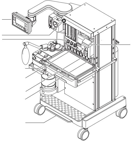
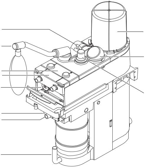
Figures 1-1 and 1-2 show the front and rear views of the machine; Figure 1-3 shows breathing system components. There are some differences between models:
•Breathing systems can be on the left or right side. The part locations are the mirror image.
•ANSI and ISO systems use the same pneumatic manifold rotated 180°. Viewed from the rear, ANSI units have the pneumatic outlet on the right and ISO units have it on the left.
•All models use the same relative cylinder positions with the O2 cylinder farthest from the breathing system.
•ANSI and ISO systems use the same flowhead assembly but the flowmeter modules are in opposite order.
•Machines include active or passive gas scavenging.
•Options include an auxiliary common gas outlet (ACGO), different breathing
circuit modules (Circle and Bain/Mapleson D), a CO2 (absorber) bypass, a suction regulator and an auxiliary O2 flowmeter (in display arm), a folding mount display bracket in place of the display arm.
1-4 |
09/06 1006-0452-000 |
8
7
6
5
4
3
2
1
1.Brake
2.System switch
3.Pressure gauges (cylinder)
4.Pressure gauges (pipeline)
5.O2 Flush
6.Flow controls
7.Light switch and connector
8.Ventilator display
9.Vaporizers
Figure 1-1 • Aestiva with 7900 Ventilator (front view)
1 Introduction
9
AA.96.054
1006-0452-000 09/06 |
1-5 |

Aestiva Anesthesia Machine
7 |
6 |
8
1 |
2 |
3 |
4 |
AA.96.053 |
5 |
|
1.Circuit breaker(Total outlet current)
2.Circuit breaker (mains inlet)
3.Pneumatic power outlet(O2 — DISS or ISO)
4.Pipeline inlets
5.Cylinder connections
6.Outlet circuit breaker
7.Electrical outlet
8.Overflow safety trap (optional suction regulator)
Figure 1-2 • Aestiva (rear view)
1-6 |
09/06 1006-0452-000 |
1 Introduction
8
9
7
10
6
5
4
11
3
2
AB.23.003
1
1.Canister release
2.Auxiliary common gas outlet — ACGO (optional)
3.ACGO switch
4.O2 sensor
5.Flow sensor module
6.Circuit module
7.Bag arm
8.Bag/Vent switch
9.Bellows
10.Airway pressure gauge
11.APL valve
Figure 1-3 • Breathing system parts
1006-0452-000 09/06 |
1-7 |

Aestiva Anesthesia Machine
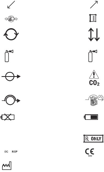
1.5 Symbols used in the manual or on the equipment
Symbols replace words on the equipment, on the display, or in Datex-Ohmeda manuals. No one device or manual uses all of the symbols.
Warnings and Cautions tell you about dangerous conditions that can occur if you do not follow all instructions in this manual:
•Warnings tell about a condition that can cause injury to the operator or the patient.
•Cautions tell about a condition that can cause damage to the equipment.
Read and follow all warnings and cautions.
m |
On (power) |
|
|
L |
Off (power) |
l |
Standby |
n |
Standby or preparatory state for part of |
the equipment |
|
M |
“ON” only for part of the equipment |
N |
“OFF” only for part of the equipment |
† |
Direct current |
p |
Alternating current |
xProtective earth ground
yEarth ground
P |
Frame or chassis ground |
YEquipotential
A
j
J
D w
wW
O
Alarm silence
Alarm silence
Type B equipment
Type BF equipment
Type CF equipment
Caution, ISO 7000-0434
Attention, refer to product instructions, IEC 60601-1
Dangerous voltage
Electrical input
Electrical output
Pneumatic input
Pneumatic output
1-8 |
09/06 1006-0452-000 |
+
-
t
T o
g
z
Z
U
u
Í
134°C
Plus, positive polarity
Minus, negative polarity
Variability
Variability in steps
Lamp, lighting, illumination
This way up
Pipeline
Lock
Unlock
Close drain
Drain (remove condensate)
Not autoclavable
Autoclavable
APL settings are approximate
k E
r R
O2+
1 Introduction
Movement in one direction
Movement in two directions
Read top of float
Read to center of float
Vacuum inlet
Suction bottle outlet
Cylinder
Isolation transformer
Linkage system
Risk of Explosion.
Low pressure leak test
Mechanical ventilation
Bag position/ manual ventilation
O2 Flush button
1006-0452-000 09/06 |
1-9 |
Aestiva Anesthesia Machine
q Inspiratory flow
Inspiratory flow
Pinch hazard
Circle breathing circuit module
The primary regulator is set to pressure
< 345 kPa
less than 345 kPa (50 psi)
Absorber on
Absorber off (CO2 Bypass active)
No battery/battery failure
REF |
Stock Number |
|
|
|
|
SN |
Serial Number |
|
|
|
|
|
|
Authorized representative in the European |
|
|
Community |
|
|
Manufacturer |
|
|
|
Q
< 414 kPa
MAX
Expiratory flow
Expiratory flow
Submenu
Bain/Mapleson D breathing circuit module
The primary regulator is set to pressure less than 414 kPa (60 psi)
CO2 Bypass Option
EZchange Canister (CO2 bypass)
Battery in use. Bar indicates amount of battery power remaining.
Maximum
Caution: federal law prohibits dispensing without prescription.
Systems with this mark agree with the European Council Directive (93/42/EEC) for Medical Devices when they are used as specified in their User’s Reference manuals. The xxxx is the certification number of the Notified Body used by Datex-Ohmeda’s Quality Systems.
1-10 |
09/06 1006-0452-000 |
2 Theory of Operation
In this section |
2.1 Theory overview . . . . . . . . . . . . . . . . . . . . . . . . . . . . . . . . . . . . . . . . . . . . . . . . . . . . . . . . . . |
. .2-2 |
|
2.2 Gas flow through the anesthesia machine . . . . . . . . . . . . . . . . . . . . . . . . . . . . . . . . . . . . |
. .2-2 |
|
2.2.1 Overview . . . . . . . . . . . . . . . . . . . . . . . . . . . . . . . . . . . . . . . . . . . . . . . . . . . . . . . . . . |
.2-2 |
|
2.2.2 Physical connections . . . . . . . . . . . . . . . . . . . . . . . . . . . . . . . . . . . . . . . . . . . . . . . . |
.2-6 |
|
2.2.3 Induction machine . . . . . . . . . . . . . . . . . . . . . . . . . . . . . . . . . . . . . . . . . . . . . . . . . . |
.2-8 |
|
2.2.4 Wall-rail mount machine . . . . . . . . . . . . . . . . . . . . . . . . . . . . . . . . . . . . . . . . . . . . |
2-10 |
|
2.2.5 System switch . . . . . . . . . . . . . . . . . . . . . . . . . . . . . . . . . . . . . . . . . . . . . . . . . . . . . |
2-12 |
|
2.2.6 Flow control . . . . . . . . . . . . . . . . . . . . . . . . . . . . . . . . . . . . . . . . . . . . . . . . . . . . . . . |
2-13 |
|
2.3 Flow through the breathing system . . . . . . . . . . . . . . . . . . . . . . . . . . . . . . . . . . . . . . . . . . |
2-15 |
|
2.3.1 Overview of flow paths . . . . . . . . . . . . . . . . . . . . . . . . . . . . . . . . . . . . . . . . . . . . . . |
2-15 |
|
2.3.2 Manual ventilation — Circle Module. . . . . . . . . . . . . . . . . . . . . . . . . . . . . . . . . . . . |
2-16 |
|
2.3.3 Mechanical ventilation — Circle Module . . . . . . . . . . . . . . . . . . . . . . . . . . . . . . . . |
2-19 |
|
2.3.4 Fresh gas flow . . . . . . . . . . . . . . . . . . . . . . . . . . . . . . . . . . . . . . . . . . . . . . . . . . . . . |
2-22 |
|
2.3.5 Different breathing circuit modules . . . . . . . . . . . . . . . . . . . . . . . . . . . . . . . . . . . . |
2-24 |
|
2.3.6 CO2 Bypass . . . . . . . . . . . . . . . . . . . . . . . . . . . . . . . . . . . . . . . . . . . . . . . . . . . . . . . |
2-25 |
|
2.3.7 Auxiliary Common Gas Outlet (ACGO) . . . . . . . . . . . . . . . . . . . . . . . . . . . . . . . . . . |
2-26 |
|
2.4 Electrical and pneumatic signals . . . . . . . . . . . . . . . . . . . . . . . . . . . . . . . . . . . . . . . . . . . . |
2-27 |
|
2.4.1 Summary of signals . . . . . . . . . . . . . . . . . . . . . . . . . . . . . . . . . . . . . . . . . . . . . . . . |
2-27 |
|
2.4.2 Subfloor tubing and wiring connections . . . . . . . . . . . . . . . . . . . . . . . . . . . . . . . . |
2-30 |
|
2.4.3 Breathing circuit module ID . . . . . . . . . . . . . . . . . . . . . . . . . . . . . . . . . . . . . . . . . . |
2-31 |
|
2.4.4 Control panel switches . . . . . . . . . . . . . . . . . . . . . . . . . . . . . . . . . . . . . . . . . . . . . . |
2-32 |
|
2.4.5 Canister switch . . . . . . . . . . . . . . . . . . . . . . . . . . . . . . . . . . . . . . . . . . . . . . . . . . . . |
2-33 |
|
2.5 Ventilator monitoring and control . . . . . . . . . . . . . . . . . . . . . . . . . . . . . . . . . . . . . . . . . . . |
2-34 |
|
2.5.1 Summary of ventilator function . . . . . . . . . . . . . . . . . . . . . . . . . . . . . . . . . . . . . . . |
2-34 |
|
2.5.2 Volume Mode . . . . . . . . . . . . . . . . . . . . . . . . . . . . . . . . . . . . . . . . . . . . . . . . . . . . . |
2-34 |
|
2.5.3 Pressure Mode . . . . . . . . . . . . . . . . . . . . . . . . . . . . . . . . . . . . . . . . . . . . . . . . . . . . |
2-34 |
|
2.5.4 PEEP . . . . . . . . . . . . . . . . . . . . . . . . . . . . . . . . . . . . . . . . . . . . . . . . . . . . . . . . . . . . |
2-35 |
|
2.5.5 O2 Monitoring . . . . . . . . . . . . . . . . . . . . . . . . . . . . . . . . . . . . . . . . . . . . . . . . . . . . . |
2-35 |
|
2.5.6 Volume Monitoring . . . . . . . . . . . . . . . . . . . . . . . . . . . . . . . . . . . . . . . . . . . . . . . . . |
2-35 |
|
2.5.7 Volume Compensation . . . . . . . . . . . . . . . . . . . . . . . . . . . . . . . . . . . . . . . . . . . . . . |
2-35 |
|
2.5.8 Pressure Waveform . . . . . . . . . . . . . . . . . . . . . . . . . . . . . . . . . . . . . . . . . . . . . . . . |
2-36 |
1006-0452-000 09/06 |
2-1 |
Aestiva Anesthesia Machine
2.1 Theory overview
This section describes:
•The flow of gas through the anesthesia machine.
•The flow of gas through the breathing system.
•Electrical signals between the anesthesia machine, including the breathing system, and the ventilator.
Note Newer machine variants include individual pipeline inlet manifolds in place of the single pneumatic manifold used in previous production machines. Additionally, the common gas manifold has been redesigned (check valve removed) and the second regulator (O2 Flush and Aux O2) has been eliminated.
2.2Gas flow through the anesthesia machine
2.2.1Overview Figure 2-4 shows the portion of the pneumatic circuit that is affected by the
individual pipeline inlet manifolds and the changes to the common gas manifold.
Figure 2-5 shows the complete pneumatic circuit with the original pneumatic manifold.
Gas supplies (items 1–6) Gas enters the system through a pipeline (2) or cylinder (4) connection. All connections have indexed fittings, filters, and check valves (one-way valves). Gauges show the cylinder (3) and pipeline (1) pressures.
A primary regulator (5) decreases the cylinder pressures to approximately pipeline levels. A pressure relief valve (6) helps protect the system from high pressures.
To help prevent problems with the gas supplies:
•Install yoke plugs on all empty cylinder connections.
•When a pipeline supply is connected, keep the cylinder valve closed.
O2 flow (items 7–14, 27) Pipeline or regulated cylinder pressure supplies O2 directly to the pneumatic outlet and to the ventilator supply connection (7a). A second regulator (13) (not used in newer machine variants) decreases the pressure for the flush valve (14a) and the auxiliary flowmeter (27).
The flush valve supplies high flows of O2 to the fresh gas outlet when you push the flush button. The flush pressure switch (14b) monitors activation of the flush valve.
When the system switch (8) is On, O2 flows to the rest of the system and there is a minimum flow of 25 to 75 mL/min through the O2 flowmeter (12).
A secondary regulator (10) supplies a constant O2 pressure to the flowmeter.
An electrical switch (9) monitors the O2 supply pressure. If the pressure is too low, an alarm appears on the ventilator display.
2-2 |
09/06 1006-0452-000 |

|
A |
|
A |
28 |
30 |
|
|
|
30 |
|
29 |
E |
|
|
B |
|
B |
A |
A |
A |
30 |
30 |
30 |
|
|
AA.96.381 |
B |
|
B |
B |
|
A.Cylinder Supply
B.Pipeline Inlet Manifold
E.Common Gas Manifold
Figure 2-4 • Pneumatic circuit diagram (machines with individual pipeline inlet manifolds)
Air, N2O, and third gas flow Pipeline or regulated cylinder pressure supplies Air (7b) directly to the (items 7b, 8, and 15–23) ventilator (Air Ventilators). When the system switch (8) is On, air flows to the
rest of the system. A secondary regulator (18) supplies the air flow control valve. Because there is no balance regulator, air flow continues at the set rate (19) during an O2 supply failure.
Balance regulators (15, 21) control the N2O and the optional gas (CO2, Heliox) pressure supply to the needle valve flow controls (16, 22). O2 secondary regulator pressure at a pilot port controls the output of the balance regulator. N2O, CO2, and Heliox output pressures drop with decreasing O2 supply pressure and shut off hypoxic gas flow before the O2 supply pressure reaches zero.
A chain link system (Link-25) on the N2O and O2 flow controls (16, 11) helps keep the O2 concentration higher than 21% (approximate value) at the common gas outlet.
Mixed gas (items 24–26) The mixed gas goes from the flowmeter outlet, through the vaporizer manifold and vaporizer (25) that is On, to the fresh gas outlet, and into the breathing system. A pressure relief valve (26) limits the maximum outlet pressure.
2 Theory of Operation
|
A |
|
|
A |
A |
28 |
30 |
|
|
|
|
|
30 |
30 |
|
29 |
|
E |
|
|
A |
A |
30 30
B


 C
C
31 |
31 |
31 |
31 |
D |
A. Cylinder Supply |
|
A. Cylinder Supplies |
|
B. Pneumatic Manifold |
|
B. Pneumatic Manifold |
|
C. Flowmeter Head |
|
C. Flowmeter Head |
|
D Vaporizer Manifold |
|
D. Vaporizer Manifold |
AA.96.389 |
E. Common Gas Manifold |
|
E. Common Gas Manifold |
|
Figure 2-5 • Pneumatic circuit diagram (machines with a pneumatic manifold)
1006-0452-000 09/06 |
2-3 |

|
A |
|
|
|
|
A |
A |
A |
A |
28 |
30 |
|
|
|
|
|
|
|
|
|
30 |
30 |
30 |
30 |
|
29 |
|
|
|
E |
|
|
|
AA.96.381 |
|
|
|
|
|
|
B |
B |
B |
|


 C
C
31 |
31 |
31 |
31 |
D |
A.Cylinder Supply
B.Pipeline Inlet Manifold
C.Flowmeter Head
D Vaporizer Manifold
E. Common Gas Manifold
Figure 2-6 • Pneumatic circuit diagram (machines with individual pipeline inlet manifolds)
Aestiva Anesthesia Machine
|
A |
|
|
A |
A |
28 |
30 |
|
|
|
|
|
30 |
30 |
|
29 |
|
E |
|
|
A |
A |
30 30
B
A.Cylinder Supplies
B.Pneumatic Manifold
C.Flowmeter Head
D.Vaporizer Manifold
E.Common Gas Manifold


 C
C
31 |
31 |
31 |
31 |
D |
AA.96.389
A.Cylinder Supply
B.Pneumatic Manifold
C.Flowmeter Head
D Vaporizer Manifold
E. Common Gas Manifold
Figure 2-7 • Pneumatic circuit diagram (machines with a pneumatic manifold)
2-4 |
09/06 1006-0452-000 |

|
|
|
|
2 Theory of Operation |
Key to Numbered Components |
1. |
Pipeline pressure gauge |
||
|
2. |
Pipeline inlet |
||
|
3. |
Cylinder pressure gauge |
||
|
4. |
Cylinder inlet |
||
|
5. |
Primary regulator (cylinder pressure) |
||
|
6. |
High-pressure relief valve |
||
|
|
• For machines with pneumatic manifold (883 kPa / 128 psi)* |
||
|
|
• For machines with pipeline inlet manifolds (758 kPa / 110 psi)* |
||
|
7. |
Supply connections for the ventilator |
||
|
|
a. O2 drive gas |
||
|
|
b. Air drive gas |
||
|
8. |
System switch |
||
|
9. |
Switch for low O2 supply pressure alarm (used with the ventilator) |
||
|
10.O2 secondary regulator (207 kPa / 30 psi)* |
|||
|
11.O2 flow control valve |
|||
|
12.O2 flow tubes |
|||
|
13.O2 flush and auxiliary flowmeter regulator (131 kPa / 19 psi)* |
|||
|
14.O2 Flush |
|||
|
|
a. Flush valve |
||
|
|
b. Pressure switch (used with the ventilator) |
||
|
15.N2O balance regulator |
|||
|
16.N2O flow control valve |
|||
|
17.N2O flow tubes |
|||
|
18.Air secondary regulator (207 kPa / 30 psi)* |
|||
|
19.Air flow control valve |
|||
|
20.Air flow tube |
|||
|
21.Optional gas balance regulator |
|||
|
22.Optional gas flow control valve |
|||
|
23.Optional gas flow tube |
|||
|
24.Vaporizer port valve |
|||
|
25.Vaporizer |
|||
|
26.Low-pressure relief valve (38 kPa / 5.5 psi)* |
|||
|
27.Auxiliary flowmeter (optional) |
|||
|
28.Common gas outlet (CGO) |
|||
|
29.Pneumatic outlet (O2) |
|||
|
30.Test port (primary regulator) |
|||
|
31.Test port (secondary/balance regulator) |
|||
|
* Approximate values |
|||
Key to Symbols |
|
|
|
Pneumatic Connection |
|
|
|
|
Filter |
|
|
|
|
|
|
|
|
|
Direction of Flow |
|
|
|
|
Check Valve |
1006-0452-000 09/06 |
2-5 |

Aestiva Anesthesia Machine
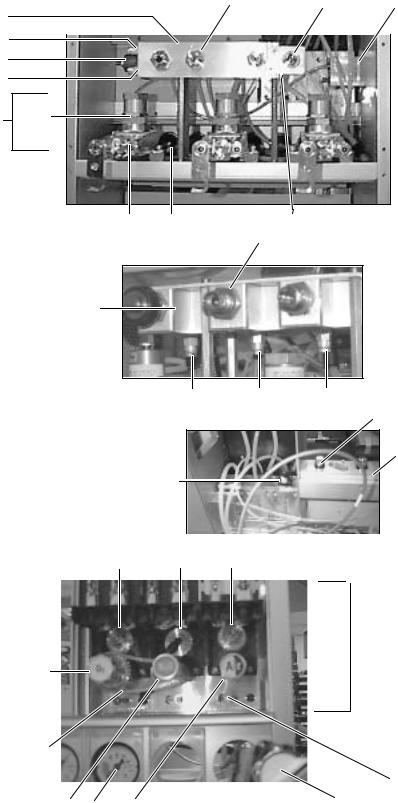
2.2.2 Physical
connections
Figure 2-5 shows the physical path that the gas takes in machines with a pneumatic manifold. To show all connections, the gas manifold (B) and the flowhead (C) have the front and the back views next to each other. For tubing connections in machines with individual pipeline inlet manifolds, refer to Section 8.37.2.
Figure 2-6 shows some of the actual parts.
|
|
|
|
24 |
|
|
|
|
|
|
|
|
|
|
|
D |
|
|
|
|
C |
|
|
|
|
26 |
|
|
|
|
|
|
|
|
|
|
|
18 |
15 |
10 |
9 |
|
AA.96.278 |
|
|
|
|
|
|
|
||||
|
|
|
|
|
Air |
|
|
12 |
17 |
20 |
|
|
|
|
|
N2O |
O2 |
O2 |
N2O |
Air |
|
|
|
|
|
|
8 |
|
|
|
|
|
|
|
|
|
|
31 |
31 |
31 |
|
|
|
|
|
|
|
|
|
|
|
|
|
O2+ |
|
|
|
|
|
|
27 |
|
|
|
14a |
|
|
|
|
|
|
|
|
|
|
|
6a |
|
|
B |
29 |
O2 |
|
|
|
|
|
|
2 |
2 |
2 |
7b Air |
|
|
|
|
|
|
13 |
O2 |
N2O |
Air |
29 |
B |
|
|
|
|
|
6b |
N2O |
|
|
|
|
|
||||
|
|
|
6c |
|
|
|
|
E |
|
|
|
|
|
|
|
|
|
|
|
|
|
|
|
|
|
|
|
|
7a |
|
14b |
|
|
|
|
|
|
|
|
|
|
|
|
1 |
|
1 |
3 |
|
3 |
|
3 |
|
|
|
|
1 |
|
|
|
|
|
|
|
||
|
|
|
5 |
|
5 |
|
5 |
|
|
|
|
|
|
4 |
|
4 |
|
4 |
|
|
|
|
|
|
O2 |
|
N2O |
|
Air |
|
|
To |
|
|
|
|
|
|
|
|
|
|
Breathing |
|
|
|
|
30 |
30 |
|
|
30 |
|
System |
|
|
|
|
|
|
|
|
|||
Figure 2-5 • Typical tubing connections - pictorial |
|
|
|
|
|
|
||||
2-6 |
|
|
|
|
|
|
|
|
09/06 |
1006-0452-000 |
2 Theory of Operation
Pneumatic |
2 |
29 |
E |
Manifold |
|
|
|
B |
|
|
|
6a |
|
|
|
|
|
|
|
13 |
|
|
|
6b |
|
|
|
A5
|
|
4 |
30 |
6c |
1 |
Pipeline pressure gauge |
Rear |
|
2 |
2Pipeline inlet
3 Cylinder pressure gauge
4Cylinder inlet
5Primary regulators (cylinder pressure)
6a |
O2 high-pressure relief valve |
G |
6b |
N2O high-pressure relief valve |
Individual |
6c |
Air high-pressure relief valve |
Pipeline |
7a* |
Vent drive gas (O2) |
Inlets |
7b* |
Vent drive gas (Air) |
|
8System switch
9Switch, low O2 supply pressure alarm
10 |
O2 secondary regulator |
6a |
6b |
6c |
11 |
O2 flow control valve |
|
|
24 |
12O2 flowtubes
13Flush regulator
14a* |
O2 Flush valve |
|
|
|
|
|
|
|
|
|
D |
14b* |
O2 Flush pressure switch (Vent feedback) |
|
|
|
|
|
|
|
|
|
|
15 |
N2O balance regulator |
|
9 |
|
|
|
|
|
|
|
|
16 |
N2O flow control valve |
|
|
|
|
|
|
|
|
|
|
17* |
N2O flowtubes |
Front |
|
|
|
|
|
|
|
|
|
18 |
Air secondary regulator |
|
|
|
|
|
|
|
|
|
|
19 |
Air flow control valve |
|
|
|
|
|
|
|
|
|
|
|
|
|
|
|
|
|
|
|
|
||
20* |
Air flowtube |
|
|
|
|
|
|
|
|
|
|
21** |
Optional gas balance regulator |
10 |
15 |
18 |
|
|
|
|
|
|
|
22** |
Optional gas flow control valve |
|
|
|
|
|
|
|
|
|
|
23** |
Optional gas flowtubes |
|
|
|
|
|
|
|
|
|
|
|
|
|
|
|
|
|
|
|
|
||
24 |
Vaporizer port valve |
|
|
|
|
|
|
|
|
|
|
25** |
Vaporizers |
|
|
|
|
|
|
|
|
|
|
26 |
Low-pressure relief valve |
|
|
|
|
|
|
|
|
|
|
27 |
To auxiliary O2 Flowmeter |
|
|
|
|
|
|
|
|
C |
|
|
|
|
|
|
|
|
|
||||
28** |
Common gas outlet (CGO) |
|
|
|
|
|
|
|
|
|
|
29 |
Pneumatic outlet (O2) |
11 |
|
|
|
|
|
|
|
|
|
30 |
Test ports (primary regulator) |
|
|
|
|
|
|
|
|
|
|
31 |
Test ports (secondary/balance regulators) |
|
|
|
|
|
|
|
|
|
|
ACylinder supplies
BPneumatic manifold
CFlowhead
D |
Vaporizer manifold |
F |
|
E |
Common gas manifold |
||
|
FChain link hypoxic guard (LINK-25)
G |
Individual pipeline inlet manifolds |
|
|
|
31 |
|
* |
Not shown pictorially |
16 |
1 |
19 |
8 |
|
** |
Not shown |
|||||
|
||||||
|
|
|
|
Figure 2-6 • Typical components
1006-0452-000 09/06 |
2-7 |
Aestiva Anesthesia Machine
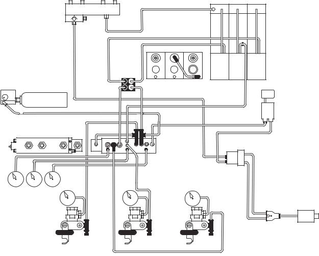
2.2.3 Induction machine The Induction machine does not include a breathing system or a ventilator. Mixed gas and O2 Flush output from the common gas manifold (E) flow directly to the Common Gas Outlet (CGO) at the front of the machine.
A pneumatic alarm assembly (9) taps into the O2 supply at the pneumatic manifold (B) and sounds the O2 Supply Failure alarm when O2 pressure falls below the threshold.
The alarm assembly consists of three parts: a canister (G) that hold a volume of pressurized O2, a pressure regulator (H), and a whistle (I) that sounds the alarm. The regulator keeps the canister pressurized as long as the supply pressure is higher than the alarm limit. When supply pressure falls below the alarm limit, the regulator releases the pressure from the canister through the whistle alarm.
AB.96.309
Air |
N2O |
O2 |
O2 |
N2O |
Air |
9
O2+
|
Air |
O2 |
B |
O2 N2O |
Air |
N2O |
|
E
O2 |
N2O |
Air |
CGO |
Figure 2-7 • Induction machine tubing
2-8 |
09/06 1006-0452-000 |
Loading...