


 Loading...
Datex-Ohmeda
E-Modules
Technical Reference Manual
Conformity according to the Council Directive 93/42/EEC concerning Medical Devices amended by 2007/47/EEC. CAUTION: U.S. Federal law restricts this device to sale by or on the order of a licensed medical practitioner. Outside the USA, check local laws for any restriction that may apply.
All specifications subject to change without notice.
Order code for the Datex-Ohmeda E-Modules Technical Reference Manual, paper: M1065282 Order code for the S/5 Technical Reference Manuals CD: M1220141
4th edition November 19, 2012
GE Healthcare Finland Oy Kuortaneenkatu 2, FI-00510 Helsinki Finland
Tel: +358 10 39411
Fax: +358 9 1463310 www.gehealthcare.com
2012, 2011 General Electric Company. All rights reserved.
Responsibility of the manufacturer
GE Healthcare Finland Oy (GE) is responsible for the effects on safety, reliability and performance of the equipment only if:
•assembly, extensions, readjustments, modifications, servicing and repairs are carried out by personnel authorized by GE.
•the electrical installation of the monitor room complies with appropriate requirements.
•the equipment is used in accordance with the "User's Guide" and serviced and maintained in accordance with the “Technical Reference Manual”.
The manufacturer reserves the right to change product specifications without prior notice. Although the information in this manual is believed to be accurate and reliable, the manufacturer assumes no responsibility for its use.
Trademarks
S/5, D-lite, D-lite+, Pedi-lite, Pedi-lite+, Mini D-fend, D-fend, D-fend+, MemCard, ComBar, ComWheel, EarSat, FingerSat, FlexSat, PatientO2, Entropy and Patient Spirometry are trademarks of GE Healthcare Finland Oy.
Datex, Ohmeda, and OxyTip+ are trademarks of GE Healthcare Finland Oy and Datex-Ohmeda, Inc.
A portion of the Entropy software is derived from the RSA Data Security, Inc. MD5 Message-Digest Algorithm.
Masimo SET
Masimo SET is a licensed trademark of Masimo Corporation.
All other product and company names are property of their respective owners.
Product availability
Some of the products mentioned in this manual may not be available in all countries. Please, consult your local representative for the availability.

Master Table of Contents
Datex-Ohmeda E-Modules
M1065282
Description |
|
|
|
|
|
Respiratory Modules, E-sCAiOV, E-sCAiO, E-sCOV and E-sCO |
1 |
|
|
Compact Airway Modules, E-CAiOVX, E-CAiOV, |
2 |
E-CAiO, E-COVX, E-COV and E-CO |
|
|
|
PRESTN Modules, E-PRESTN, E-RESTN, E-PRETN |
3 |
|
|
Patient Side Modules, E-PSM, E-PSMP rev. 01 |
4 |
|
|
Cardiac Output Modules E-COP rev. 01 and E-COPSv rev. 01 |
5 |
|
|
Pressure Module, E-P, Pressure Temp Module, E-PT |
6 |
|
|
Dual Pressure Module, E-PP |
7 |
|
|
Masimo Module, E-MASIMO |
8 |
|
|
Nellcor Compatible Saturation Module, E-NSAT, E-NSATX |
9 |
|
|
Single-width Airway Module, E-miniC |
10 |
|
|
Tonometry Module, E-TONO |
11 |
|
|
Entropy Module, E-ENTROPY |
12 |
|
|
EEG Module, E-EEG rev.00 and EEG Headbox, N-EEG rev. 01 |
13 |
|
|
BIS Module, E-BIS rev. 01 |
14 |
|
|
NeuroMuscular Transmission Module, E-NMT |
15 |
|
|
Device Interfacing Solution, N-DISxxx rev. 01 |
16 |
|
|
Interface Module, E-INT |
17 |
|
|
Recorder Module, E-REC |
18 |
|
|
Memory Module, E-MEM |
19 |
|
|
Remote Controllers, K-REMCO rev. 01, K-CREMCO |
20 |
|
|
Anesthesia record keeping keyboard, K-ARKB, Keyboard Interface Board, |
21 |
B-ARK and ARK Barcode Reader, N-SCAN |
|
|
|
E-Modules, Spare Parts |
22 |
|
|
i
Document no. M1181405B

Datex-Ohmeda E-Modules
ii
Document no. M1181405B

About this manual
Notes to the reader
This Technical Reference Manual is intended for service personnel and engineers who will service and maintain the Datex-Ohmeda E-Modules as well as the anesthesia record keeping keyboard, K-ARKB, remote controllers, K-REMCO and K-CREMCO, Device Interfacing Solution, N-DISxxx, keyboard interface board, B-ARK, and ARK barcode reader, N-SCAN.
This Technical Reference Manual completes the S/5 Anesthesia Monitor and S/5 Critical Care Monitor Technical Reference Manual and the S/5 Compact Anesthesia Monitor and
S/5 Compact Critical Care Monitor Technical Reference Manual. Later in this manual, the monitors may be referred to as AM, CCM, CAM and CCCM.
The order code for the Datex-Ohmeda E-Modules Technical Reference Manual is M1065282.
The order code for the S/5 Technical Reference Manuals CD is M1220141. S/5 AM, CCM Technical Reference Manual, S/5 CAM, CCCM Technical Reference Manual and Datex-Ohmeda E-Modules Technical Reference Manual are included on the CD.
Each manual on the CD has an individual document number and is available for downloading from GE Common Document Library in Adobe Acrobat PDF format.
•This Technical Reference Manual contains the information needed to maintain, service and troubleshoot these products. Instructions for visual and functional inspection, disassembly and reassembly as well as calibration of the modules are included. A service check form for each product is included in the slots.
•In addition, this Technical Reference Manual contains detailed module specifications and descriptions on the technical performance and functioning of the modules.
•Read the manual through and make sure that you understand the procedures described before servicing the modules. To avoid risks concerning safety or health, strictly observe the warning indications. If you need any assistance concerning the service, please do not hesitate to contact your authorized distributor.
For information on safety precautions and symbols on equipment, installation, planned maintenance and interfacing, refer to the AM and CCM Technical Reference Manual or the CAM and CCCM Technical Reference Manual.
The manufacturer reserves the right to change product specifications without prior notice. Although the information in this manual is believed to be accurate and reliable, the manufacturer assumes no responsibility for its use.
GE Healthcare assumes no responsibility for the use or reliability of its software in equipment that is not furnished by GE Healthcare.
Related documentation
S/5 AM, CCM Technical Reference Manual S/5 CAM, CCCM Technical Reference Manual
For more specific information about the clinical aspects refer to: S/5 monitor’s User’s Guide
S/5 monitor’s User’s Reference Manual
1
Document no. M1181405B

Datex-Ohmeda E-Modules
Conventions used
Hard Keys
Throughout this manual, the following conventions are used to distinguish procedures or elements of text:
Sign the check form after performing the procedure.
Hard key names on the Command Board, the Remote Controller and modules are written in the following way: ECG.
Menu Items |
Menu items are written in bold italic: ECG Setup. |
‘Messages’ |
Messages displayed on the screen are written inside single quotes: ‘Please wait’. |
“Sections” |
When referring to different sections in the same manual, the section name is enclosed in |
|
double quotes: section “Cleaning and Service.” |
“Other documents”
When referring to different documents, the document name is enclosed in double quotes: refer to “User’s Reference Manual”.
Hypertext links |
Hypertext links on PDF versions are written in blue color. |
WARNING |
Warnings are written in the following way: |
WARNING |
Make sure that the electrodes, sensor and connectors do not touch any |
|
electrically conductive material, including earth. |
CAUTION |
Cautions are written in the following way: |
CAUTION |
The module electronics can only be repaired and calibrated at the factory. |
NOTE |
Notes are written in following way: |
|
NOTE: Handle all PC boards by their edges. |
In this manual, the word “select” means choosing and confirming.
Revision history
Revision |
Date |
Comment |
|
|
|
1st edition |
10 May 2011 |
Initial |
|
|
|
2nd edition |
22 Sep 2011 |
Order code for paper manual added. |
|
|
|
3rd edition |
19 June 2012 |
E-PSM rev. 01, E-PSMP rev. 01, E-COP rev.01 and E-COPSv rev. 01 |
|
|
update. |
|
|
|
4th edition |
19 Nov 2012 |
Respiratory Modules E-sCAiOV, E-sCAiO, E-sCOV and E-sCO added . |
|
|
|
2
Document no. M1181405B

GE Healthcare
Respiratory Modules, E-sCAiOV, E-sCAiO, E-sCOV, E-sCO
Technical Reference Manual Slot
Conformity according to the Council Directive 93/42/EEC concerning Medical Devices amended by 2007/47/EEC. CAUTION: U.S. Federal law restricts this device to sale by or on the order of a licensed medical practitioner. Outside the USA, check local laws for any restriction that may apply.
All specifications subject to change without notice.
Document number M1214853C
June 21, 2012
GE Healthcare Finland Oy Kuortaneenkatu 2, FI-00510 Helsinki Finland
Tel: +358 10 39411
Fax: +358 9 1463310 www.gehealthcare.com
2012 General Electric Company. All rights reserved.

Table of contents
Table of contents
Introduction |
1 |
1 Technical specifications |
3 |
1.1 Physical characteristics . . . . . . . . . . . . . . . . . . . . . . . . . . . . . . . . . . . . . . . . . . . . . . . . . . . . . . . . . . . . . . . 3 1.2 Operating characteristics . . . . . . . . . . . . . . . . . . . . . . . . . . . . . . . . . . . . . . . . . . . . . . . . . . . . . . . . . . . . . 3 1.3 Airway gases . . . . . . . . . . . . . . . . . . . . . . . . . . . . . . . . . . . . . . . . . . . . . . . . . . . . . . . . . . . . . . . . . . . . . . . . . 3 1.3.1 General characteristics . . . . . . . . . . . . . . . . . . . . . . . . . . . . . . . . . . . . . . . . . . . . . . . . . . . . . . . . . 3 1.3.2 Respiration rate . . . . . . . . . . . . . . . . . . . . . . . . . . . . . . . . . . . . . . . . . . . . . . . . . . . . . . . . . . . . . . . . 3 1.3.3 Carbon dioxide . . . . . . . . . . . . . . . . . . . . . . . . . . . . . . . . . . . . . . . . . . . . . . . . . . . . . . . . . . . . . . . . . 4 1.3.4 Oxygen . . . . . . . . . . . . . . . . . . . . . . . . . . . . . . . . . . . . . . . . . . . . . . . . . . . . . . . . . . . . . . . . . . . . . . . . 4 1.3.5 Nitrous oxide. . . . . . . . . . . . . . . . . . . . . . . . . . . . . . . . . . . . . . . . . . . . . . . . . . . . . . . . . . . . . . . . . . . 4 1.3.6 Anesthetic agents . . . . . . . . . . . . . . . . . . . . . . . . . . . . . . . . . . . . . . . . . . . . . . . . . . . . . . . . . . . . . . 5 1.3.7 Non-disturbing gases. . . . . . . . . . . . . . . . . . . . . . . . . . . . . . . . . . . . . . . . . . . . . . . . . . . . . . . . . . . 5 1.3.8 Gas cross effects . . . . . . . . . . . . . . . . . . . . . . . . . . . . . . . . . . . . . . . . . . . . . . . . . . . . . . . . . . . . . . . 5
1.4 Patient Spirometry . . . . . . . . . . . . . . . . . . . . . . . . . . . . . . . . . . . . . . . . . . . . . . . . . . . . . . . . . . . . . . . . . . . . 6 1.4.1 General characteristics . . . . . . . . . . . . . . . . . . . . . . . . . . . . . . . . . . . . . . . . . . . . . . . . . . . . . . . . . 6 1.4.2 Airway pressure . . . . . . . . . . . . . . . . . . . . . . . . . . . . . . . . . . . . . . . . . . . . . . . . . . . . . . . . . . . . . . . . 6 1.4.3 Airway gas flow . . . . . . . . . . . . . . . . . . . . . . . . . . . . . . . . . . . . . . . . . . . . . . . . . . . . . . . . . . . . . . . . 6 1.4.4 Tidal volume . . . . . . . . . . . . . . . . . . . . . . . . . . . . . . . . . . . . . . . . . . . . . . . . . . . . . . . . . . . . . . . . . . . 6 1.4.5 Minute volume . . . . . . . . . . . . . . . . . . . . . . . . . . . . . . . . . . . . . . . . . . . . . . . . . . . . . . . . . . . . . . . . . 7 1.4.6 Compliance . . . . . . . . . . . . . . . . . . . . . . . . . . . . . . . . . . . . . . . . . . . . . . . . . . . . . . . . . . . . . . . . . . . . 7 1.4.7 Airway resistance . . . . . . . . . . . . . . . . . . . . . . . . . . . . . . . . . . . . . . . . . . . . . . . . . . . . . . . . . . . . . . 7 1.4.8 Inspiration to expiration ratio . . . . . . . . . . . . . . . . . . . . . . . . . . . . . . . . . . . . . . . . . . . . . . . . . . . 7
2 Functional description |
8 |
2.1 Measurement principle. . . . . . . . . . . . . . . . . . . . . . . . . . . . . . . . . . . . . . . . . . . . . . . . . . . . . . . . . . . . . . . . 8 2.1.1 CO2, N2O, and agent measurement . . . . . . . . . . . . . . . . . . . . . . . . . . . . . . . . . . . . . . . . . . . . . 8 2.1.2 O2 measurement. . . . . . . . . . . . . . . . . . . . . . . . . . . . . . . . . . . . . . . . . . . . . . . . . . . . . . . . . . . . . . 10 2.1.3 Patient spirometry. . . . . . . . . . . . . . . . . . . . . . . . . . . . . . . . . . . . . . . . . . . . . . . . . . . . . . . . . . . . . 10
2.2 Main components. . . . . . . . . . . . . . . . . . . . . . . . . . . . . . . . . . . . . . . . . . . . . . . . . . . . . . . . . . . . . . . . . . . . 12 2.2.1 Controls and connectors. . . . . . . . . . . . . . . . . . . . . . . . . . . . . . . . . . . . . . . . . . . . . . . . . . . . . . . 12 2.2.2 Gas sampling system. . . . . . . . . . . . . . . . . . . . . . . . . . . . . . . . . . . . . . . . . . . . . . . . . . . . . . . . . . 13 2.2.3 MiniTPX measuring unit. . . . . . . . . . . . . . . . . . . . . . . . . . . . . . . . . . . . . . . . . . . . . . . . . . . . . . . . 16 2.2.4 MiniOM Oxygen sensor . . . . . . . . . . . . . . . . . . . . . . . . . . . . . . . . . . . . . . . . . . . . . . . . . . . . . . . . 17 2.2.5 MiniPVX measuring unit . . . . . . . . . . . . . . . . . . . . . . . . . . . . . . . . . . . . . . . . . . . . . . . . . . . . . . . 19 2.2.6 CPU board . . . . . . . . . . . . . . . . . . . . . . . . . . . . . . . . . . . . . . . . . . . . . . . . . . . . . . . . . . . . . . . . . . . . 20 2.2.7 MiniOM board . . . . . . . . . . . . . . . . . . . . . . . . . . . . . . . . . . . . . . . . . . . . . . . . . . . . . . . . . . . . . . . . . 20 2.2.8 MiniPVX board . . . . . . . . . . . . . . . . . . . . . . . . . . . . . . . . . . . . . . . . . . . . . . . . . . . . . . . . . . . . . . . . 21 2.2.9 Main Component Interactions . . . . . . . . . . . . . . . . . . . . . . . . . . . . . . . . . . . . . . . . . . . . . . . . . 21
3 Service Procedures |
22 |
3.1 Replacement of planned maintenance parts . . . . . . . . . . . . . . . . . . . . . . . . . . . . . . . . . . . . . . . . . . 23 3.1.1 Required parts . . . . . . . . . . . . . . . . . . . . . . . . . . . . . . . . . . . . . . . . . . . . . . . . . . . . . . . . . . . . . . . . 23 3.1.2 Planned Maintenance Kits . . . . . . . . . . . . . . . . . . . . . . . . . . . . . . . . . . . . . . . . . . . . . . . . . . . . . 23
i
Document no. M1214853C

Datex-Ohmeda E-Modules
3.1.3 Replacement procedures . . . . . . . . . . . . . . . . . . . . . . . . . . . . . . . . . . . . . . . . . . . . . . . . . . . . . . 23 3.2 Visual inspections. . . . . . . . . . . . . . . . . . . . . . . . . . . . . . . . . . . . . . . . . . . . . . . . . . . . . . . . . . . . . . . . . . . . 24 3.3 Functional check. . . . . . . . . . . . . . . . . . . . . . . . . . . . . . . . . . . . . . . . . . . . . . . . . . . . . . . . . . . . . . . . . . . . . 25 3.3.1 Test setup. . . . . . . . . . . . . . . . . . . . . . . . . . . . . . . . . . . . . . . . . . . . . . . . . . . . . . . . . . . . . . . . . . . . . 25 3.3.2 Procedure. . . . . . . . . . . . . . . . . . . . . . . . . . . . . . . . . . . . . . . . . . . . . . . . . . . . . . . . . . . . . . . . . . . . . 25 3.3.3 Test completion . . . . . . . . . . . . . . . . . . . . . . . . . . . . . . . . . . . . . . . . . . . . . . . . . . . . . . . . . . . . . . . 30
3.4 Disassembly and reassembly . . . . . . . . . . . . . . . . . . . . . . . . . . . . . . . . . . . . . . . . . . . . . . . . . . . . . . . . . 30 3.4.1 Disassembly guidelines . . . . . . . . . . . . . . . . . . . . . . . . . . . . . . . . . . . . . . . . . . . . . . . . . . . . . . . . 30 3.4.2 Disassembly and reassembly procedure. . . . . . . . . . . . . . . . . . . . . . . . . . . . . . . . . . . . . . . . 32
3.5 Adjustments and calibration. . . . . . . . . . . . . . . . . . . . . . . . . . . . . . . . . . . . . . . . . . . . . . . . . . . . . . . . . . 42 3.5.1 Sample Flow Rate Adjustment . . . . . . . . . . . . . . . . . . . . . . . . . . . . . . . . . . . . . . . . . . . . . . . . . 42 3.5.2 Gas Calibration. . . . . . . . . . . . . . . . . . . . . . . . . . . . . . . . . . . . . . . . . . . . . . . . . . . . . . . . . . . . . . . . 43 3.5.3 Spirometry Calibration. . . . . . . . . . . . . . . . . . . . . . . . . . . . . . . . . . . . . . . . . . . . . . . . . . . . . . . . . 45
4 Troubleshooting |
47 |
4.1 Visual inspection. . . . . . . . . . . . . . . . . . . . . . . . . . . . . . . . . . . . . . . . . . . . . . . . . . . . . . . . . . . . . . . . . . . . . 47 4.2 Troubleshooting checklist . . . . . . . . . . . . . . . . . . . . . . . . . . . . . . . . . . . . . . . . . . . . . . . . . . . . . . . . . . . . 47 4.2.1 Gas sampling system troubleshooting. . . . . . . . . . . . . . . . . . . . . . . . . . . . . . . . . . . . . . . . . . 48 4.2.2 MiniOM Measuring unit troubleshooting . . . . . . . . . . . . . . . . . . . . . . . . . . . . . . . . . . . . . . . . 48 4.2.3 MiniTPX Measuring unit troubleshooting . . . . . . . . . . . . . . . . . . . . . . . . . . . . . . . . . . . . . . . . 48 4.2.4 MiniPVX Measuring unit troubleshooting. . . . . . . . . . . . . . . . . . . . . . . . . . . . . . . . . . . . . . . . 48 4.2.5 CPU board troubleshooting . . . . . . . . . . . . . . . . . . . . . . . . . . . . . . . . . . . . . . . . . . . . . . . . . . . . 49
4.3 Service Interface. . . . . . . . . . . . . . . . . . . . . . . . . . . . . . . . . . . . . . . . . . . . . . . . . . . . . . . . . . . . . . . . . . . . . 49 4.4 Messages . . . . . . . . . . . . . . . . . . . . . . . . . . . . . . . . . . . . . . . . . . . . . . . . . . . . . . . . . . . . . . . . . . . . . . . . . . . 50 4.4.1 Gas measurements. . . . . . . . . . . . . . . . . . . . . . . . . . . . . . . . . . . . . . . . . . . . . . . . . . . . . . . . . . . . 50 4.4.2 Spirometry . . . . . . . . . . . . . . . . . . . . . . . . . . . . . . . . . . . . . . . . . . . . . . . . . . . . . . . . . . . . . . . . . . . . 53
4.5 Troubleshooting charts. . . . . . . . . . . . . . . . . . . . . . . . . . . . . . . . . . . . . . . . . . . . . . . . . . . . . . . . . . . . . . . 54 4.5.1 CO2 measurement . . . . . . . . . . . . . . . . . . . . . . . . . . . . . . . . . . . . . . . . . . . . . . . . . . . . . . . . . . . . 54 4.5.2 Patient spirometry. . . . . . . . . . . . . . . . . . . . . . . . . . . . . . . . . . . . . . . . . . . . . . . . . . . . . . . . . . . . . 54
5 Spare parts |
56 |
5.1 Ordering parts . . . . . . . . . . . . . . . . . . . . . . . . . . . . . . . . . . . . . . . . . . . . . . . . . . . . . . . . . . . . . . . . . . . . . . . 56 5.1.1 Planned Maintenance Kits . . . . . . . . . . . . . . . . . . . . . . . . . . . . . . . . . . . . . . . . . . . . . . . . . . . . . 56 5.2 Spare parts for E-sCAiOV, E-sCAiO, E-sCOV, E-sCO. . . . . . . . . . . . . . . . . . . . . . . . . . . . . . . . . . . . . . 57 5.2.1 Front covers . . . . . . . . . . . . . . . . . . . . . . . . . . . . . . . . . . . . . . . . . . . . . . . . . . . . . . . . . . . . . . . . . . 59
6 Earlier revisions |
61 |
|
Appendix A: |
Service check form |
A-1 |
ii
Document no. M1214853C
Respiratory Modules, E-sCAiOV, E-sCAiO, E-sCOV, E-sCO
Introduction
This document provides information for the maintenance and service of the CARESCAPE Respiratory modules, E-sCO, E-sCOV, E-sCAiO and E-sCAiOV. The CARESCAPE Respiratory modules are single width plug-in modules.
The CARESCAPE Respiratory modules provide airway and respiratory measurements. Letters in the module name stand for:
C = CO2 and N2O, O = patient O2, V = patient spirometry, A = anesthetic agents, and i = agent identification
Table 1 Options for CARESCAPE Respiratory modules
Modules |
Parameters / measurements |
|
|
|||
|
|
|
|
|
|
|
|
CO2 |
N2O |
O2 |
Anesthetic |
Agent ID |
Spirometry |
|
|
|
|
agents |
|
|
|
|
|
|
|
|
|
E-sCOV |
X |
X |
X |
|
|
X |
|
|
|
|
|
|
|
E-sCO |
X |
X |
X |
|
|
|
|
|
|
|
|
|
|
E-sCAiOV |
X |
X |
X |
X |
X |
X |
|
|
|
|
|
|
|
E-sCAiO |
X |
X |
X |
X |
X |
|
|
|
|
|
|
|
|
NOTE: Anesthetic agents and N2O values are not displayed with ICU and ED software packages, but when present in the module they are calculated for compensation of CO2 and O2.
|
|
|
Figure 1 Airway gases measurement setup
(1)CARESCAPE Respiratory Module
(2)Gas sample, gas sampling line connector on the water trap
(3)Gas sampling line
(4)Gas sampling line connector on the airway adapter; place the connector upwards
(5)Airway adapter with sampling line connector
(6)Heat and moisture exchanger with filter (HMEF) (optional)
1
Document no. M1214853C

Datex-Ohmeda E-Modules
System compatibility
The CARESCAPE Respiratory Modules can be used for respiratory monitoring in the following S/5 monitors:
S/5 Anesthesia Monitor, software versions L-ANE06(A) 24.1 or later
S/5 Critical Care Monitor, software versions L-ICU06(A) 24.1 or later
S/5 Compact Anesthesia Monitor, software versions L-CANE05(A) 19.6 or later
S/5 Compact Critical Care Monitor, software versions L-CICU05(A) 19.6 or later
NOTE: Low sample gas flow situation is indicated with the message Replace D-Fend in the L-xxx06(A) software versions 24.1 and L-xxx05(A) software versions 19.6.
NOTE: The CARESCAPE Respiratory Modules cannot be used in the S/5 Extension Frame.
2
Document no. M1214853C

|
|
Respiratory Modules, E-sCAiOV, E-sCAiO, E-sCOV, E-sCO |
|
|
|
1 |
Technical specifications |
|
1.1 |
Physical characteristics |
|
|
Size (H x W x D) |
112 x 37 x 205 mm ( 4.4 x 1.5 x 8.7 in) |
|
Weight |
0.75 kg (1.5 lb) |
|
Power consumption |
3.9 W |
1.2 |
Operating characteristics |
|
|
Warm-up time |
|
|
- CO2, O2 and N2O measurements: |
1 minute |
|
-Anesthetic agent measurement |
|
|
and identification: |
5 minutes |
|
Gas sampling rate: |
120 ±20 ml/min |
|
Automatic compensation for ambient pressure. |
|
|
Operating conditions |
|
|
Ambient temperature: |
+10°C to +40°C |
|
Ambient pressure: |
660 mbar to 1060 mbar |
|
Ambient humidity: |
10%RH to 98%RH, non-condensing |
1.3 |
Airway gases |
|
1.3.1 |
General characteristics |
|
|
Specifications are valid at the following normal operating conditions: |
|
|
Ambient temperature: |
+18°C to +28°C, within ±5°C of calibration |
|
Ambient pressure: |
660 mbar to 1060 mbar, ±67 mbar of calibration |
|
Ambient humidity: |
20%RH to 80%RH, non-condensing, ±20%RH of calibration |
|
Sampling line length: |
2, 3 and 6 meters |
|
Respiration rate: |
4 to 70 breaths/minute |
|
|
(Halothane 4 to 50 breaths/minute) |
|
Airway pressure: |
-20 mbar to +100 mbar |
|
Module operating time: |
>20 minutes continuously |
NOTE: The displayed ranges of parameter values depend on the host device. For more information, refer to the host device’s user documentation.
1.3.2 Respiration rate
Breath detection: |
1 vol% change in CO2 level |
Measurement range: |
4 to 100 breaths/min |
Accuracy |
|
at 4 to 20 breaths/min: |
±1 breath/min |
at 20 to 100 breaths/min: |
±5% |
RR value is updated breath-by-breath. |
|
3
Document no. M1214853C

Datex-Ohmeda E-Modules
1.3.3 Carbon dioxide
Measurement range: |
0 vol% to 15 vol%, 0 kPa to 15 kPa, |
|
0 mmHg to 113 mmHg |
Accuracy: |
±(0.2 vol% +2% of reading) |
Total system response time: |
< 3.0 s |
Rise time: |
< 260 ms |
CO2 drift: |
< 0.1 vol% |
EtCO2 and FiCO2 values are updated breath-by-breath.
Description of test method, data rate, and method of ET-calculation
The module uses gas concentration waveforms with data rate of 25Hz to calculate end-tidal (ET) gas readings.
The module finds the time instant of the highest CO2 concentration in each breath. Concentration at that instant is the ET CO2 reading. Because nitrous oxide and anesthetic agents are measured by the same sensor as CO2, the ET-readings of those gases are obtained directly at the time instant of ET CO2. For calculating ET-readings of oxygen, the module synchronizes the O2-waveform with the CO2 waveform. The ET-reading of O2 is then determined as O2-concentration at the time instant of ET CO2. If no breaths are detected for a given time (20s, for example), an apnea situation is triggered. During apnea, the ET values are updated every two seconds to the current concentration of each gas.
The rated respiration rate range and the corresponding end-tidal gas reading accuracy were tested with reference gases of known concentrations. The test gases were fed to the gas sampling system of the module through an electrically actuated valve with very low internal volume. Depending on its actuation status, the valve directed either room air or a test gas to the gas sampling line. The desired respiration rates were set by the electrical actuating times of the valve.
The measurement accuracy of the end-tidal gas readings was tested using gas sampling lines of 3 meter length, connected to the gas sample port on the D-fend Pro water trap. The gas sampled to the sampling line was switched from room air to the test gases using an electrically actuated valve with low internal dead space to generate step changes in the gas concentrations. The electric actuating signal of the valve was generated using a higly accurate signal generator to accurately control the simulated respiration rate.
The electronic sampling rate of the gas sensor signals is 25Hz, equaling a new data point on the gas waveform traces every 40 milliseconds.
1.3.4 Oxygen
Measurement range: |
0 vol% to 100 vol% |
Accuracy: |
±(1 vol% +2% of reading) |
Total system response time: |
< 3.0 s |
Rise time: |
< 260 ms |
O2 drift: |
< 0.3 vol% |
EtO2 and FiO2 values are updated breath-by-breath.
1.3.5 Nitrous oxide
Measurement range: |
0 vol% to 100 vol% |
Accuracy: |
|
at (0 < N2O < 85 vol%) |
±(2 vol% +2% of reading) |
Total system response time: |
< 3.0 s |
Rise time: |
< 320 ms |
N2O drift: |
< 0.3 vol% |
EtN2O and FiN2O values are updated breath-by-breath.
4
Document no. M1214853C

|
Respiratory Modules, E-sCAiOV, E-sCAiO, E-sCOV, E-sCO |
|
|
1.3.6 Anesthetic agents |
|
Measurement range: |
|
Sevoflurane: |
0 vol% to 8 vol% |
Desflurane: |
0 vol% to 20 vol% |
Isoflurane, enflurane, halothane: |
0 vol% to 6 vol% |
Accuracy: |
±(0.15 vol% +5% of reading) |
Total system response time: |
< 3.1 s (< 3.5 s for Halothane) |
Rise time: |
< 420 ms (< 800 ms for Halothane) |
Hal drift: |
< 0.1 vol% |
Enf drift: |
< 0.1 vol% |
Iso drift: |
< 0.1 vol% |
Sev drift: |
< 0.1 vol% |
Des drift: |
< 0.3 vol% |
EtAA and FiAA values are updated breath-by-breath. |
|
The module automatically identifies the anesthetic agent present in the sampled gas and measures the |
|
concentration of the identified agent. |
|
Identification threshold: |
0.15 vol% |
Identification time: |
< 20 s |
The module automatically identifies mixtures of two anesthetic agents present in the sampled gas and measures the concentrations of the two identified agents.
Identification threshold for the 2nd agent
at 1 MAC of the 1st agent: 0.2 vol% +10% of the concentration of the 1st agent
1.3.7 Non-disturbing gases
A gas is considered non-disturbing if its effects to the measured gas are as follows:
CO2: |
< 0.2 vol% |
O2, N2O: |
< 2 vol% |
Anesthetic agents: |
< 0.15 vol% |
The following gases are non-disturbing when tested according to ISO21647(2004B):
ethanol, acetone, isopropanol, methane, nitrogen, carbon monoxide, nitric oxide, freon R134A (for CO2, O2 and N2O), water vapor.
The effects caused by N2O to the measurement of CO2, O2 and anesthetic agents are automatically compensated for.
The effects caused by anesthetic agents to the measurement of CO2 and N2O are automatically compensated for.
1.3.8 Gas cross effects
Helium (50 vol%): |
Decreases CO2 readings by less than 0.5 vol% at 5 vol% of CO2 |
|
Decreases O2 readings by less than 2 vol% at 50 vol% of O2 |
Xenon (80 vol%): |
Decreases CO2 readings by less than 0.5 vol% at 5 vol% of CO2 |
|
Decreases O2 readings by less than 1.5 vol% at 14 vol% of O2 |
5
Document no. M1214853C

Datex-Ohmeda E-Modules
1.4 |
Patient Spirometry |
|
1.4.1 |
General characteristics |
|
|
These specifications are valid in the following operating conditions: |
|
|
The module has been operating continuously for 10 minutes |
|
|
Airway adapter, adult: |
D-lite |
|
Airway adapter, pediatric: |
Pedi-lite |
|
Respiration rate |
|
|
- adults: |
4 to 35 breaths/min |
|
- pediatric patients: |
4 to 70 breaths/min |
|
I:E ratio: |
1:4.5 to 2:1 |
|
Airway humidity: |
10 %RH to 100 %RH |
|
Ambient temperature: |
+10°C to +40°C |
|
Ambient pressure: |
660 mbar to 1060 mbar |
|
Ambient humidity: |
10 %RH to 98 %RH (non-condensing) |
|
NOTE: The displayed ranges of parameter values depend on the host device. For more information, refer |
|
|
to the host device’s user documentation. |
|
1.4.2 |
Airway pressure |
|
|
Measurement range: |
-20 cmH2O to +100 cmH2O |
|
Accuracy: |
±1 cmH2O |
|
Time resolution: |
10 ms |
|
Values calculated from the measured airway pressure data: |
|
|
Peak pressure (Ppeak) |
|
|
Plateau pressure (Pplat) |
|
|
Mean pressure (Pmean) |
|
|
Positive end expiratory pressure (PEEPtot, or PEEPi and PEEPe) |
|
|
Static positive end expiratory pressure (static PEEPe and static PEEPi) |
|
1.4.3 |
Airway gas flow |
|
|
Measurement range |
|
|
- adults: |
-100 l/min to +100 l/min |
|
- pediatic patients: |
-25 l/min to +25 l/min |
|
Time resolution: |
10 ms |
Flow measurement has automatic compensation for airway pressure and effects caused by variation in the concentrations of the gas components measured by the module.
1.4.4 Tidal volume
The module calculates the volume by integrating the measured gas flow over time. Tidal volumes (TVinsp and TVexp) are obtained as the change of volume during inspiration and expiration.
Measurement range |
|
- with D-lite: |
150 ml to 2000 ml |
- with Pedi-lite: |
5 ml to 300 ml |
Accuracy |
|
- with D-lite: |
±6% or 30 ml (whichever is greater) |
- with Pedi-lite: |
±6% or 4 ml (whichever is greater) |
6
Document no. M1214853C

Respiratory Modules, E-sCAiOV, E-sCAiO, E-sCOV, E-sCO
1.4.5 Minute volume
The module calculates the inspired and expired minute volumes as the sum of inspired (MVinsp) and expired (MVexp) gas volume during one minute.
Measurement range |
|
- with D-lite: |
2 l to 20 l |
- with Pedi-lite: |
0.5 l to 5 l |
1.4.6 Compliance
The module calculates both the compliance (Compl) and static compliance (static Compl). Compliance is calculated by dividing the expired gas volume (TVexp) by the change in the airway pressure (Pplat - PEEPtot). Static compliance is calculated by dividing TVexp by the difference of static Pplat and static PEEPtot.
Measurement range |
|
- adults: |
4 ml/cmH2O to 100 ml/cmH2O |
- pediatric patients: |
1 ml/cmH2O to 100 ml/cmH2O |
1.4.7 Airway resistance
The module calculates the airway resistance (Raw) by solving the lung model equation P(t) = Raw * F(t) + V(t) / Compl + PEEPtot
where: P(t), F(t) and V(t) are the time dependent waveforms of pressure, flow, and volume, respectively.
Measurement range: |
0 cmH2O/l/s to 40 cmH2O/l/s |
1.4.8 Inspiration to expiration ratio
The module measures ratio of the inspiratory and expiratory time (I:E).
The inspiratory time is the time from the start of inspiration to the start of expiration. The end inspiratory pause, if one exists, is included in the inspiration. Accordingly, expiratory time is the time from the start of expiration to the start of the next inspiration.
7
Document no. M1214853C

Datex-Ohmeda E-Modules
2 Functional description
2.1 Measurement principle
2.1.1 CO2, N2O, and agent measurement
MiniTPX is a side stream gas analyzer, measuring real time concentrations of CO2, N2O, and anesthetic agents (Halothane, Enflurane, Isoflurane, Desflurane, and Sevoflurane).
Figure 2 MiniTPX sensor principle
Anesthetic agents or mixtures of two anesthetic agents are automatically identified, and concentrations of the identified agents are measured. MiniTPX also detects mixtures of more than two agents and issues an alarm.
MiniTPX is a non-dispersive infrared analyzer, measuring absorption of the gas sample at seven infrared wavelengths, which are selected using optical narrow band filters.
The infrared radiation detectors are thermopiles.
Concentrations of CO2 and N2O are calculated from absorption measured at 3-5 m.
8
Document no. M1214853C

Respiratory Modules, E-sCAiOV, E-sCAiO, E-sCOV, E-sCO |
Figure 3 Absorbance of N2O and CO2
Identification of anesthetic agents and calculation of their concentrations is performed by measuring absorptions at five wavelengths in the 8-9 m band and solving the concentrations from a set of equations.
Figure 4 Infrared absorbance of AAs
The measuring accuracy is achieved utilizing numerous software compensations. The compensation parameters are determined individually for each MiniTPX during the factory calibration.
9
Document no. M1214853C

Datex-Ohmeda E-Modules
2.1.2 O2 measurement
The differential oxygen measuring unit uses the paramagnetic principle in a pneumatic bridge configuration. The signal picked up with a differential pressure transducer unit is generated in a measuring cell with a strong magnetic field that is switched on and off at a main frequency of 164 Hz. The output signal is a DC voltage proportional to the O2 concentration difference
between the gas to be measured and the air reference.
Figure 5 O2 measurement principle
2.1.3 Patient spirometry
In mechanical ventilation, breaths are delivered to the patient by a ventilator with a proper tidal volume (TV), respiration rate (RR), and inspiration / expiration ratio in time (I:E) determined by the settings of the ventilator.
The Patient Spirometry monitors patient ventilation.
The following volume parameters are displayed:
Expiratory and inspiratory tidal volume (TV) in ml
Expiratory and inspiratory minute volume (MV) in l/min
Expiratory spontaneous minute volume in l/min
Inspiration/expiration ratio (I:E)
The following airway pressure parameters are displayed:
Peak pressure (Ppeak)
Mean airway pressure (Pmean); available only in S/5 Critical Care and Compact Critical Care monitors
End inspiratory pressure (Pplat)
PEEPi, PEEPe; available only in S/5 Critical Care and Compact Critical Care monitors
Total positive end expiratory pressure (PEEPtot); available only in S/5 Anesthesia and Compact Anesthesia monitors
Real time airway pressure waveform (Paw)
Static Positive end expiratory pressures (Static PEEPi and Static PEEPe); available only in S/5 Critical Care and Compact Critical Care monitors
Static Plateau pressure (Static Pplat); available only in S/5 Critical Care and Compact Critical Care monitors
Static Compliance (Static Compl); available only in S/5 Critical Care and Compact Critical Care monitors
10
Document no. M1214853C
Respiratory Modules, E-sCAiOV, E-sCAiO, E-sCOV, E-sCO
PEEP, Ppeak, Pmean, and Pplat are measured by a pressure transducer on the MiniPVX board. Ambient pressure is used as a reference in measurement. The pressure measurement is made
from the airway part that is closest to the patient between the patient circuit and intubation tube.
PEEPi=intrinsic PEEP, PEEPtot-PEEPe
Static pressure measurement maneuvers are automatically identified based on an increased zero flow period at the end of the inspiration or expiration.
Static Compliance is calculated, if Static PEEP and Static Pplat measurements were made within a 2 minute period.
The following airway flow parameters are displayed:
Real time flow waveform (V')
Compliance (Compl)
Airway resistance (Raw)
Pressure volume loop
Flow volume loop
The measurement is based on measuring the kinetic gas pressure and is performed using the Pitot effect. A pressure transducer is used to measure the Pitot pressure. The pressure signal obtained is linearized and corrected according to the density of the gas. Speed of flow is calculated from these pressure values and the TV value is then integrated. The MV value is calculated and averaged using TV and RR (respiratory rate) values.
D-lite
Patient Spirometry uses specific sensors called D-lite+/D-lite and Pedi-lite+/Pedi-lite flow sensors. Different types of sensors are available: adult sensor for measuring adults and pediatric sensor for children. Both are available as reusable and disposable versions.
D-lite and Pedi-lite adapters are designed to measure kinetic pressure by a two-sided Pitot tube. Velocity is calculated from pressure difference according to Bernoulli's equation. Flow is then determined using the calculated velocity.
(from Bernoulli's equation) |
Formula 1 |
where:
V’ = flow (l/min), v = velocity (m/s), A = cross area (m2), dP = pressure difference (cmH2O),= density (kg/m3)
Finally, the volume information is obtained by integrating the flow signal.
Compliance and airway resistance
Compliance is calculated for each breath from the equation
Formula 2
Compliance describes how large a pressure difference is needed to deliver a certain amount of gas to the patient.
The airway resistance, Raw, is calculated using an equation that describes the kinetics of the gas flow between the lungs and the D-lite. The equation states that the pressure at the D-lite can at any moment of the breath be approximated using the equation
11
Document no. M1214853C

Datex-Ohmeda E-Modules
Formula 3
where P(t), V’(t) and V(t) are the pressure, flow and volume measured at the D-lite at a time t, Raw is the airway resistance, Compl is the compliance and PEEPe+PEEPi is the total positive end
expiratory pressure (PEEPtot).
2.2 Main components
The respiratory modules consist of:
•
•
•
•
•
Gas sampling system MiniTPX measuring unit MiniOM measuring unit MiniPVX measuring unit CPU board
2.2.1 Controls and connectors
|
|
|
|
Figure 6 Front of CARESCAPE Respiratory Module, E-sCAiOV, and the back of the module
(1)D-fend Pro water trap
(2)Gas sample, sampling line connector on the water trap
(3)Water trap container
(4)Connectors for Patient Spirometry
(5)Gas exhaust, connector for the gas exhaust line (sampling gas out
12
Document no. M1214853C
Respiratory Modules, E-sCAiOV, E-sCAiO, E-sCOV, E-sCO
Module keys |
Module |
Description |
|
|
|
Save Loop |
E-sCOV, E-sCAiOV |
Save Loop saves a reference |
|
|
loop. |
|
|
|
Change Loop |
E-sCOV, E-sCAiOV |
Change Loop changes a |
|
|
pressure/volume loop to a |
|
|
flow/volume loop or vice |
|
|
versa. |
|
|
|
Connector |
Module |
Description |
|
|
|
D25 connector |
all modules |
Module bus connector |
|
|
|
2.2.2 Gas sampling system
The gas sampling system draws a 120ml/min sample from the patient's airway to the module. The sampling system also takes about 30ml/min flow of room air to the oxygen sensor. When the gas sensors are zeroed, room air is taken through the CO2-absorber to
the gas sensors instead of the sampled gas from the patient's breathing.
The gas sampling line is connected between the patient circuit and the Gas Sample port on the water trap. The water trap protects the sampling system and gas sensors from liquids and dust.
The diagram of the gas sampling system is shown in the figure below:
|
|
|
|
|
|
|
|
|
! ! |
|
|
|
" ! |
|
|
|
|
||
|
|
|
|
' |
|
|
|
# )% |
|
|
|
|||
|
|
|
|
|
|
|
|
|
|
|
|
|
|
|
'
#( %
|
|
|
|
|
|
|
|
|
|
|
|
|
|
|
|
# $! % |
|||
|
||||
|
|
|
||
|
& |
|
||
|
|
|
||
|
|
|
||
Figure 7 Gas sampling system
13
Document no. M1214853C

Datex-Ohmeda E-Modules
The sampling system has a self diagnostics that detects disturbances in the gas flow, reveals the most common reasons for disturbances, such as occluded sampling line or blocked gas exhaust line, and communicates relevant status messages to the patient monitor.
The system is designed so that gas the sampled gas will not flow from the sampling line back to the patient circuit. The parts and connections of the sampling system are streamlined for minimal dead spaces and turbulences in gas flows.
All gas inputs of the module have dust filters protecting the sampling system and gas sensors. The water trap acts as a dust filter for the sampled gas and the module should always have the water trap connected.
NOTE: It is very important to prevent dust from entering the open gas connections during service operations.
D-fend Pro(+) water trap
The gas sampling line is connected to the input of the water trap where a special membrane passes gases and vapors but stops liquids. The gas flowing through the membrane continues via the main flow connector of the water trap to the module. The main flow is about 90% of the sample flow.
Liquids stopped below the membrane are moved to the water container by a side flow that goes through the water container and the water separation membrane before entering the side flow connector of the water trap. Thus, the side flow also is free of liquids when it gets into the module. In the module, the side flow is connected directly to the pump input and it does not enter the gas sensors.
NOTE: The water trap acts as a dust filter for the sampling system and gas sensors. Thus, the module should always have the water trap connected.
Zero valve and CO2 absorber
The zero valve is activated during gas sensor zeroing. Room air is drawn through the CO2-absorber and the zero valve to the gas sensors, and the main flow of sample gas is
stopped. The zero gas comes to the sensors through the CO2-absorber that chemically absorbs CO2. The side flow of the water trap flows in the gas sampling line even during zeroing.
During normal monitoring, the zero valve is not activated and the sampled gas gets through the zero valve to the gas sensors.
Figure 8 |
Absorber |
Nafion tubes 1)
The Nafion tube between the water trap and the zero valve equalizes the humidity of the sampled gas to ambient level. This will prevent calibration errors caused by the difference in humidities in the sampled breathing gas and the totally dry calibration gas.
Another Nafion tube is used between the CO2 absorber and the zero valve to prevent condensation of water generated in the CO2 absorber as by-product of CO2-absorption.
1 Nafion is a registered trademark of Perma Pure Inc.
14
Document no. M1214853C
Respiratory Modules, E-sCAiOV, E-sCAiO, E-sCOV, E-sCO
Gas sensors
After the zero valve, the gas flows trough the MiniTPX sensor that measures the concentrations of all gases but oxygen.
The oxygen concentration is measured in the MiniOM sensor that has two inputs. One input draws in a part of the main flow and the other draws in room air as reference gas for the O2
measurement.
Sample flow differential pressure transducer
The module measures total flow at the input of the gas pump and reference flow at the OM reference line. The sample flow is the difference of these two flows.
Working pressure transducer
The working pressure transducer measures absolute working pressure near the MiniTPX unit and MiniOM unit. It is used for messages: ‘Sample line blocked’, ‘Check D-fend’, ‘Replace D-fend’ and ‘Check sample gas out’.
Pneumatics unit
The pneumatics unit contains the zero valve, the occlusion valve and the pneumatics block with tubing connections.
The zero valve is activated during the zero level calibrations of gas sensors. The occlusion and zero valves are activated when the sampling line or water trap is occluded. With the activated valves, the gas pump generates maximal suction trough the “side flow” connector of the water trap, thus maximizing the transfer of liquids from the wet side of the water trap to the container.
The pneumatics block contains a network of constrictions to divide the sampled gas in correct proportions to different parts in the module. The first branching takes place in the water trap where incoming flow is divided to the “main flow” and “side flow”. The second branching takes place before the MiniOM sensor.
The pneumatics block also contains a pneumatic low pass filter between gas sensors and gas pump. The filter consists of constrictions (resistors) and volumes (capacitors) and it attenuates the pressure pulsation generated in the gas pump so that they do not disturb the operation of the gas sensors.
Gas pump unit
The gas pump is a membrane pump run by a brushless DC-motor. The pump is adjusted so that the sample gas flow is kept close to its nominal value even when the flow resistances in the sampling line of water trap change.
15
Document no. M1214853C
Datex-Ohmeda E-Modules
The pump is in a plastic enclosure to minimize the operating noise and mechanical vibration of the pump unit. A pneumatic damping chamber is integrated to enclosure to attenuate the pressure pulsation and noise conducted to the gas exhaust port.
Pressure measurements
The four pressure sensors on the CPU board are used to measure ambient pressure, working pressure of the MiniTPX and MiniOM sensors and pressure of the reference gas flow to the MiniOM sensor.
Sample flow control
The gas flow in the sampling line is monitored by measuring the gas flow at the input of the gas pump and the reference flow to the oxygen sensor is estimated by measuring the pressure in the reference gas flow branch. The sample flow is calculated by subtracting the reference flow from the total gas flow. A control loop adjusts the rotation speed of the pump motor so that the gas flow is kept close to 120ml/min.
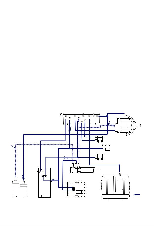
Gas sampling self-diagnostics
The sample flow and the vacuum in the sampling system are used for continuous monitoring of the gas sampling system. The vacuum is calculated in real time as difference of the measured ambient and working pressures.
The self-diagnostics of the gas sampling system sends the following status data to the patient monitor when specific triggering conditions are met: ‘Check water trap’, ‘Check sample gas out’, ‘Replace water trap’, ‘Sample line blocked’ and ‘Continuous blockage’.
The gas pump is stopped when the 'Sample line blocked' has lasted for more than 1 minute. The module automatically restarts the pump to check whether the abnormal situation has been resolved so that normal gas sampling operation is possible.
The gas pump repeats 1 minute full pump, 30 seconds pump off when the ‘Continuous blockage’ message is shown.
|
|
|
|
|
|
|
|
|
|
|
|
|
|
|
$% |
|
|
|
|
|
|
|
|
|
# |
|
|
|
|
|
|
||||
|
|
|
|
|
|
|||
|
|
|
! |
|
|
|
|
" |
|
|
|
|
|
|
|
||
|
|
|
|
|
|
|||
" |
|
|
|
|
|
|
|
|
|
|
|
|
|
|
|
||
|
|
|
! |
|
|
|
|
|
|
|
|
|
|
|
|
||
|
|
|
|
|
|
|
|
|
|
|
|
|
|
|
|
|
|
|
|
|
|
|
|
|
|
|
|
|
|
|
|
|
|
|
|
|
|
|
|
|
|
|
|
|
|
|
|
|
|
|
|
|
|
|
|
|
|
|
|
|
|
|
|
|
|
|
|
|
|
|
|
|
|
! |
|
|
|
|
|
|
Figure 9 Gas tubing layout
2.2.3 MiniTPX measuring unit
The MiniTPX unit is a non dispersive infrared analyzer, measuring the absorption of the gas sample at seven infrared wavelengths, which are selected using optical narrow band filters. The IR source is a micro-machined heating element with an integrated collimator. From the output of the source, the radiation is passed to a flow optimized measuring chamber.
16
Document no. M1214853C

Respiratory Modules, E-sCAiOV, E-sCAiO, E-sCOV, E-sCO
From the sample chamber, radiation goes via a specially designed beam splitter to two detector units, each with four thermopile detectors and integrated optical filters. The miniTPX measuring unit has two detector units for redundancy purposes. A more detailed description of the measuring principle can be found in section “2.1.1. CO2, N2O, and agent measurement”.
Each detector unit also measures the unit's temperature. The module CPU uses it for further processing and temperature compensation of the measured raw signals.
The miniTPX unit includes an amplifier board with the following functions:
•On-board 5V regulator and 2.5V reference source.
•Preamplifiers for the eight thermopile detectors and for the two temperature sensors. A 16 channel buffered multiplexer is used to transfer the signals to the CPU board.
•PWM controlled power for the IR source.
•An EEPROM memory for storing factory calibration coefficients of the sensor.
The input to the amplifier board comprises a 7V DC feed and CPU control signals for the PWM, the multiplexer and the EEPROM. When the module starts up, the calibration coefficients are read to the module CPU and then used for calculating the gas concentrations from the raw data received from the sensor multiplexer.
Figure 10 MiniTPX measuring unit
2.2.4 MiniOM Oxygen sensor
The miniOM sensor measures the concentration of Oxygen in the gas sample.
The measurement is based on the magnetic properties of oxygen. The sensor measures the sound pressure generated in the air gap of the magnet at the 164Hz operating frequency. Two microphones are used for detection and the Oxygen concentration is calculated from the RMS value of the difference of the microphone outputs. The measurement principle is described in more detail in section ”2.1.2. O2 measurement”.
The sensor consists of the following functional parts
•
•
•
•
Pneumatic system Amplifier board MiniOM board Magnet
17
Document no. M1214853C

Datex-Ohmeda E-Modules
The sensor is shown in the picture below.
Figure 11 MiniOM oxygen sensor
NOTE: The sensor is assembled in the module using flexible suspension to prevent the mechanical vibrations of the gas pump and cooling fan from disturbing the Oxygen measurement. All gas lines to the sensor must also be carefully assembled so that they do not pick up mechanical vibrations of the module mechanics.
Pneumatic System
The pneumatic system, together with the gas sampling system of the module creates the gas flows and pressures needed for the oxygen measurement and protection of the microphones from excessive pressure. About 30 ml/min flow of sampled gas comes to the In connector on the MiniOM sensor. Room air is drawn to the Ref input of MiniOM also at 30 ml/min rate. About 75% of these flows are conducted to a pressure equalization chamber so that only about a
8 ml/min flow of the two gas streams continue into the air gap of the magnet. All the internal gas flows finally get to a volume enclosed by the sensor board and the sensor body, and then flow out through the Out connection of the sensor. Some of the gas channels and flow restrictors are integrated into the preamplifier electronics board utilizing the multi-layer structure of the LTCC (Low Temperature Co-fired Ceramics) circuit board technology.
NOTE: It is very important to prevent dust or liquids from getting into the pneumatic circuit of MiniOM and thus, the gas connections should always be closed with a protecting cap when the sensor is not connected to the module pneumatics.
Amplifier Board
The amplifier board located in the sensor has two electric microphones for the differential detection of pressure pulses generated in the magnet's air gap. The microphone signals are fed to two identical signal conditioning channels with a band-pass filter and a digitally controlled amplifier. The voltage gains of the amplifiers are set during factory calibration so that the responses of the microphone channels match in spite of differences in microphone's sensitivities. The amplifier board also has an amplifier for the thermistor measuring the temperature of the magnet.
MiniOM Board
The MiniOM board has five functions
•
•
•
•
Drive the magnet coil.
Convert the microphone and temperature signals into digital format. Filter digitally the microphone signals and perform the RMS-conversion. Communicate digitally with the module CPU.
18
Document no. M1214853C

Respiratory Modules, E-sCAiOV, E-sCAiO, E-sCOV, E-sCO
•Store factory calibration data in permanent memory and communicate them to the module CPU.
The module CPU provides the coil drive and communication enabling signals and also clock signal for MiniOM board. The FPGA takes care of the coil drive and has also back-up clock in case of CPU clock does not work. The FPGA takes care of the A/Dconversions which are performed with a serial controlled SAR A/D-converter.
The digital band pass filtering and RMS conversion of the microphone signals is made with FPGA circuit controlled by the VHDL code stored in the circuit. In order to filter out the disturbances caused by acoustic noise, mechanical vibration and amplifier noise, the band pass filters are designed to have as narrow a pass band as possible without slowing down the filter's response to changes in the amplitude of the 164 Hz signal.
The FPGA circuit takes care of the digital communication between the miniOM sensor and the module CPU.
The factory calibration coefficients of the sensor are stored in an EEPROM memory on the miniOM board. When the module starts up, the calibration coefficients are read to the module CPU and then used for calculating the O2 concentration from the Oxygen raw data received from the sensor.
2.2.5 MiniPVX measuring unit
NOTE: Never apply the overpressure or negative pressure of more than 300 cmH2O to the flow and volume tubing. Differential pressure max 25 cmH2O is allowed on one port at a time e.g. when connecting tubes.
When Patient Spirometry is used, a special sensor, D-lite, replaces the normal airway adapter in the patient circuit. A double lumen tubing is attached to the two connectors on the adapter and on the module front panel.
The Patient Spirometry provides patient respiration monitoring capabilities using the D-lite and Pedi-lite flow sensors.
Figure 12 MiniPVX measuring unit
The measurement is based on measuring the kinetic gas pressure and is performed using the Pitot effect. A pressure transducer is used to measuring the Pitot pressure. The signal is then linearized and corrected according to the density of the gas. Speed of the flow is calculated from the pressure and TV is integrated from it.
19
Document no. M1214853C

Datex-Ohmeda E-Modules
Patient Spirometry consists of airway connections, two pressure transducers, valves and preamplifiers. The preamplifiers are connected to the A/D-converter on the module main CPU.
The patient’s breathing flow passing through the D-lite adapter creates a pressure difference. This pressure difference is measured by a pressure transducer, B1. Overpressure and negative pressure in airways are measured by another pressure transducer, B2.
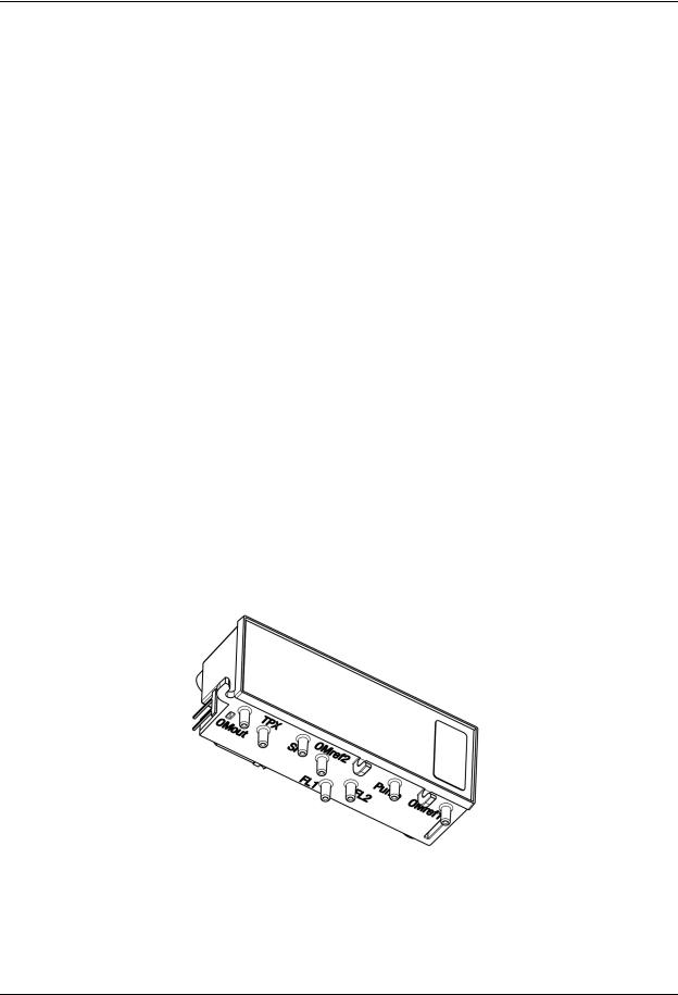
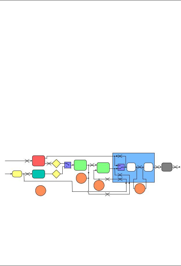
2.2.6 CPU board
The CPU board contains the processor, memories and an A/D-converter that is common to the whole module.
The CPU board also contains sensors for pressure, temperature and humidity as well as drivers for valves, the fan and the pump. The module is connected to the module bus through an RS-485 serial channel.
|
|
|
|
|
|
2 ) 3
.
|
3 ) |
|
|
|
|
|
|
|
|
3 )/ |
& '& |
|
|
|
|
|
|
|
''# |
|
) )) / |
|
|
|||
|
( |
|
|
|
||||
|
3. |
|
|
|
|
|
||
|
) |
|
|
|
|
|
||
|
3 |
|
|
|
|
|||
|
|
|
|
|
|
$ |
||
|
|
|
|
|
|
|
|
|
|
|
|
|
|
|
|
|
|
|
|
|
|
|
|
|
||
|
|
|
|
|
|
|
|
0 |
+ #0 |
"-./0 |
|
12& / |
|||||
|
|
|
||||||
|
|
|
|
|
|
|
|
|
1
& 1
|
|
|
|
|
|
|
|
|
|
||||||
|
|
|
|
|
|
|
|
|
|
|
|
|
|
||
|
|
|
|
|
|
|
|
*+" * ,, |
|
|
|
|
|
||
|
|
|
|
|
|
|
|
|
|
|
|
|
|
|
|
|
|
|
|
|
|
|
|
|
|
|
|
|
|
|
4 |
|
|
|
|
|
|
|
|
|
|
|
|
|
|
|
|
|
|
|
|
|
|
|
|
|
|
|
|
|
|
|
|
|
|
|
|
|
|
|
|
|
|
|
|
||||
|
|
|
|
|
|
|
|
|
|
|
|
||||
|
|
|
|
|
|
|
|
|
|
|
|
|
|
|
|
|
|
&" |
|
|
|
|
|
|
|
|
|
|
|
|
|
|
|
$ |
|
|
|
|
|
|
|
|
|
|
|
|
|
|
|
|
|
|
|
|
|
|
|
|
|
|
|
||
|
|
|
|
|
|
|
|
|
|
|
|
|
|
|
|
|
" 5 2 |
|
|
|
|
|
|
|
|
|
|
|
|
||
|
|
/ $ |
|
|
|
|
|
|
|
|
|
|
|
|
|
|
|
|
|
|
|
|
|
|
|
|
|
|
|
|
|
|
|
|
|
|
|
|
|
|
|
|
|
|
|
|
|
|
|
) |
|
|
|||||||||||
|
|
! ,- |
|
|
|
|
|
|
|
|
|
|
|
||
|
|
|
|
|
|
|
|
|
|
|
|
|
|
|
|
|
|
) |
|
|
|
|
|
|
|
|
|
|
$ |
||
|
|
)!./ ,- |
|
|
|
|
|
|
|
|
|
|
|
||
Figure 13 Signal processing on CPU board
2.2.7 MiniOM board
The miniOmM board contains electronics specific to the MiniOM sensor: FPGA circuit, coil drive, A/D-converter etc. It also contains EEPROM memory that stores calibration data of the oxygen measurement.
20
Document no. M1214853C
Loading...