

Page 1

Datex-Ohmeda
S/5™ 8-Module Frame, F-CU8 (Rev. 07)
Technical Reference Manual
Datex-Ohmeda Inc.
3030 Ohmeda Drive
MADISON, WI 53718
U.S.A.
Tel. +1-608-221 1551 Fax +1-608-2229147
www.us.datex-ohmeda.com
All specifications are subject to change without notice.
Document No. 8001003-2
October 2001
Datex-Ohmeda Division,
Instrumentarium Corp.
P.O. Box 900, FIN-00031
DATEX-OHMEDA, FINLAND
Tel. +358 10 394 11 Fax +358 9 146 3310
www.datex-ohmeda.com
Instrumentarium Corp. All rights reserved.
Page 2

Page 3

Table of contents
TABLE OF CONTENTS
8-module frame, F-CU8
TABLE OF CONTENTS i
TABLE OF FIGURES ii
Introduction 1
1 Specifications 2
1.1 8-Module Frame, F-CU8............................................................................................................................2
1.1.1 Electrical requirements.....................................................................................................................2
1.1.2 Environmental requirements .............................................................................................................2
2 Functional Description 3
2.1 8-Module Frame, F-CU8............................................................................................................................3
2.1.1 Power supply unit.............................................................................................................................4
2.1.2 CPU mother board ..........................................................................................................................12
2.1.3 Module mother board .....................................................................................................................12
2.2 Connectors and signals...........................................................................................................................12
2.2.1 Internal connectors.........................................................................................................................12
3 Service Procedures 15
3.1 General service information.....................................................................................................................15
3.2 Service check .........................................................................................................................................15
3.2.1 Recommended tools ......................................................................................................................15
3.2.2 Recommended parts......................................................................................................................15
3.3 Disassembly and reassembly..................................................................................................................21
3.3.1 Power supply unit...........................................................................................................................22
3.3.2 Lead acid battery............................................................................................................................22
3.3.3 Changing fuses...............................................................................................................................22
3.4 Adjustments and calibrations..................................................................................................................22
4 Troubleshooting 23
4.1 Troubleshooting flowcharts......................................................................................................................23
4.1.1 Monitor..........................................................................................................................................23
4.1.2 Central Unit....................................................................................................................................24
4.1.3 Digital section................................................................................................................................25
5Service MENU 26
5.1 Service menu structure ...........................................................................................................................26
5.2 Service...................................................................................................................................................27
5.3 Service menu .........................................................................................................................................28
5.4 Frame ....................................................................................................................................................28
5.4.1 Power Supply.................................................................................................................................29
6 Spare Parts 30
6.1 Spare parts list .......................................................................................................................................30
6.1.1 8-Module Frame, F-CU8 rev. 01......................................................................................................30
6.1.2 8-Module Frame, F-CU8 rev. 02......................................................................................................32
6.1.3 8-Module Frame, F-CU8 rev. 03......................................................................................................32
Document No. 8001003-2
i
Page 4

Datex-Ohmeda S/5 AM and S/5 CCM
6.1.4 8-Module Frame, F-CU8 rev. 04......................................................................................................32
6.1.5 8-Module Frame, F-CU8 rev. 05......................................................................................................32
6.1.6 8-Module Frame, F-CU8 rev. 06......................................................................................................33
6.1.7 8-Module Frame, F-CU8 rev. 07......................................................................................................33
7 Earlier Revisions 34
APPENDIX A 35
SERVICE CHECK FORM A-1
TABLE OF FIGURES
Figure 1 8-Module Frame, F-CU8 .......................................................................................................................1
Figure 2 Basic structure of S/5 Monitor, an example of possible configuration.....................................................3
Figure 3 Power supply unit block diagram...........................................................................................................4
Figure 4 Mains part and display outlet block diagram..........................................................................................5
Figure 5 Power supply board block diagram........................................................................................................7
Figure 6 Power logic board block diagram ........................................................................................................10
Figure 7 Monitor troubleshooting flowchart .......................................................................................................23
Figure 8 Central Unit troubleshooting flowchart.................................................................................................24
Figure 9 Digital section troubleshooting flowchart .............................................................................................25
ii
Document No. 8001003-2
Page 5
INTRODUCTION
This section provides information for the maintenance and service of the following products:
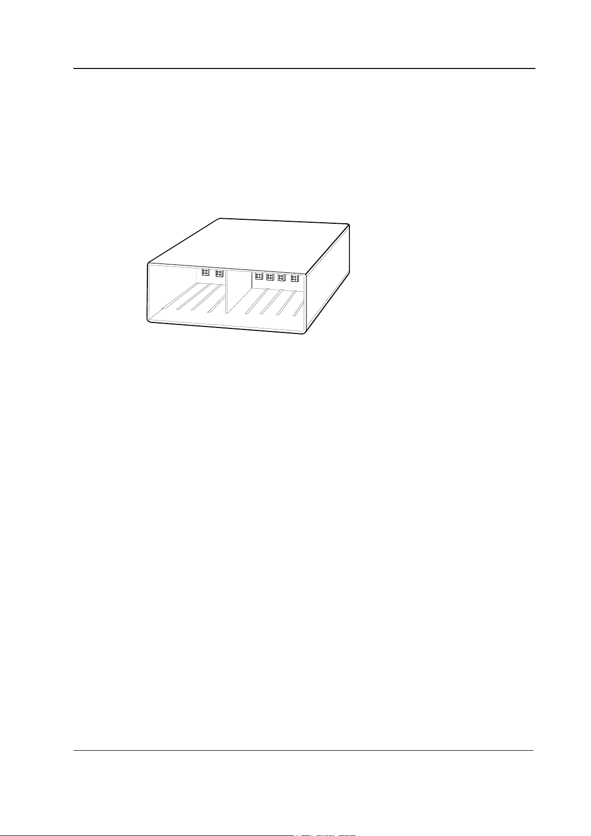
• 8-Module Frame, F-CU8 (also called Central Unit)
8-Module Frame, F-CU8 (Rev. 07)
• Power supply unit
• CPU mother board
• Module mother board
Figure 1 8-Module Frame, F-CU8
Document No 8001003-2
1
Page 6

Datex-Ohmeda S/5 AM and S/5 CCM
1 SPECIFICATIONS
1.1 8-Module Frame, F-CU8
Dimensions, D ×××× W ×××× H 382 ×××× 315 ×××× 128 mm (15.0 ×××× 12.4 ×××× 5.0 in)
Weight 9.5 kg (21 lbs)
1.1.1 Electrical requirements
Power supply 100, 110-120, 220-240 VAC 50/60 Hz, 1.2 A (for whole system)
Stability ±10 % of nominal voltage
Power consumption 280 VA
Grounding Hospital grade
Interruptibility Data memory and alarm settings are saved during power failures up
1.1.2 Environmental requirements
to 15 minutes
Operating temperature 10...35 °C / 50...95 °F
Storage temperature -10...+50 °C / 14...122 °F
Atmospheric pressure 660...1060 hPa (660...1060 mbar)
Humidity 10...90 % non-condensing (in airway 0...100 % condensing)
2
Document No. 8001003-2
Page 7
2 FUNCTIONAL DESCRIPTION
2.1 8-Module Frame, F-CU8
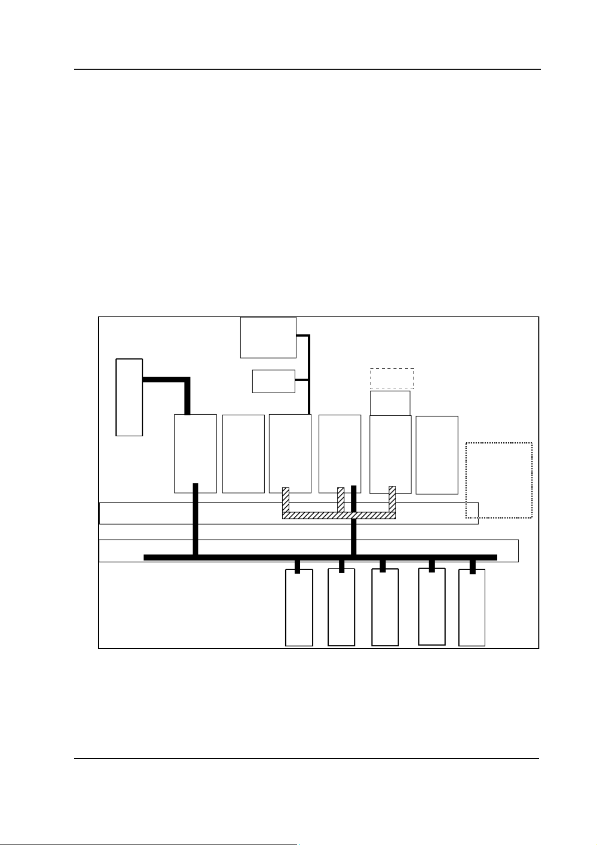
To operate S/5 Anesthesia Monitor or S/5 Critical Care Monitor, the following products should be
installed into the frame
• CPU board, B-CPU4 w/ main software
• UPI4 or UPI4NET board, B-UPI4 or B-UPI4NET
• Display controller board, B-DISP
The frame has two sections. The front part is for the modules. On the between the front and rear
parts, there are module mother board and CPU mother board. The module mother board connects
modules to the system, and the CPU mother board connects boards together.
Display
8-Module Frame, F-CU8 (Rev. 07)
Airway Module
CPU Mother Board
Module Mother Board
Gas
Interface
Board
Command
Board
Display
Controller
Board
CPU Bus
Module Bus
COP Module
UPI
Board
P Module
Software Card
w/ B-CPU4
Software Cartridge
w/ B-CPU2/3
CPU
Board
ESTP Module
NIBP Module
Power
Supply
Unit
Recorder Module
Figure 2 Basic structure of S/5 Monitor, an example of possible configuration
Document No 8001003-2
3
Page 8
Datex-Ohmeda S/5 AM and S/5 CCM
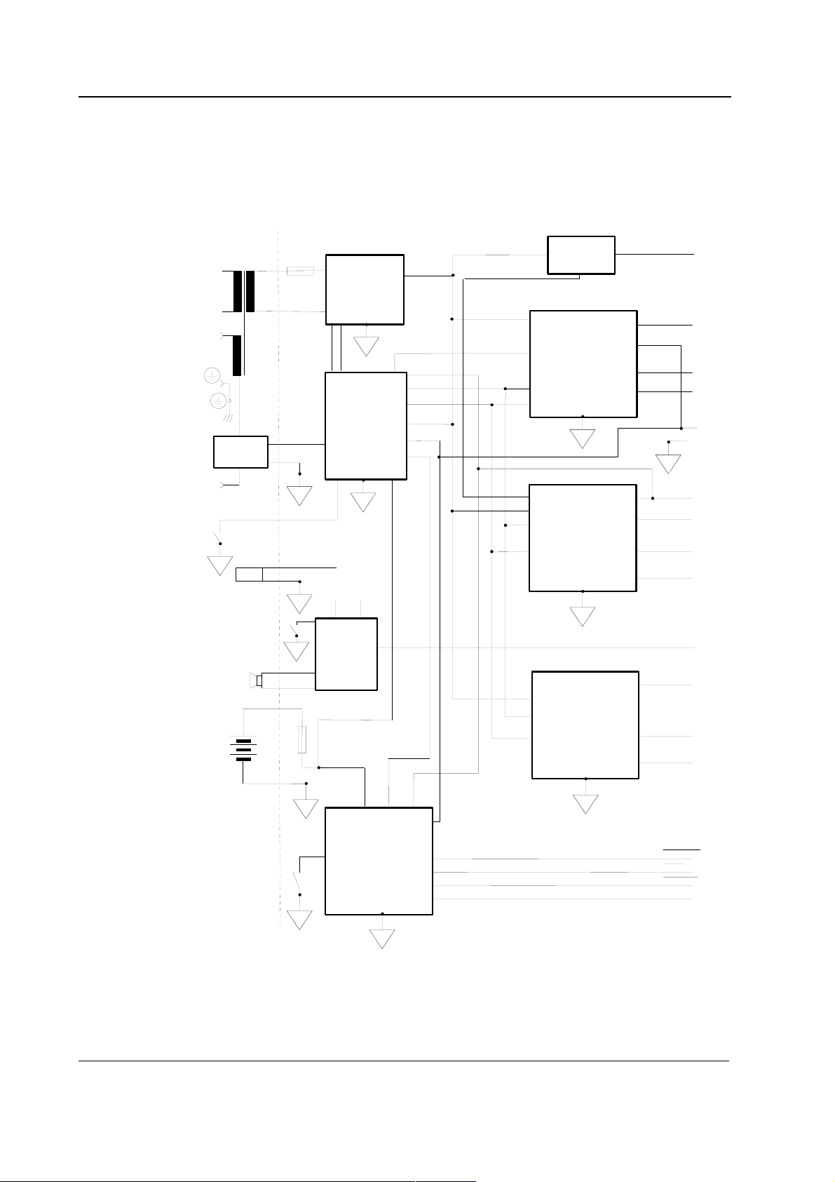
2.1.1 Power supply unit
Power supply unit contains three PC boards (power supply board, power logic board, and triac
board) and four external components (mains transformer, fan, loudspeaker, and lead acid battery).
All the operational controls in the power supply unit are located in the three PC boards.
DISPLAY
OUTLET
DISPLAY
OUTLET
ON/STBY
SW ITCH
ON
COM MAND
BOAR D
MAINS
TRANSFOR MER
TRIAC
BOARD
c
FAN
SILENCE ALARM
DIP SW ITCH
ON POW ER
SUPPLY BO ARD
LO U D SPEAKER
T 10 A
TRIA C
c
c
c
RECTIFIERS,
POW ER
FAC TO R
CORRECTION
*P O W E R
ON/STBY
CONTROL,
BATCHRG,
etc.
+32 V d
15 V d
*AUDIO
AM P.
c
c
+5 Vcpu
+5 V int
ON/STBY
32 V
+32 Vd
SW ITCH
-1 5 V
CONVERTER
c
+ 1 5 V
CONVERTER
c
+32 V d
-1 5 V
f(-15V )
st(-15V )
+5 V cpu
GND
c
+15 V d
+15 V a
f(+15 V )
st(+15 V)
AUDIOin
+5 V
4
Document No. 8001003-2
6 V
BATTERY
2AF
BATCHRG
STOP
c
SERVICE
RESET
BUTTON
*C P U
IN T E R F A C E
c
c
*P O W ER O N /S TB Y C O N TR O L, AU D IO A M P ., and C P U IN TER FA C E are in P ow er
Logic B oard. A ll other functions are in Pow er S upply B oard.
Figure 3 Power supply unit block diagram
+ 5 V
CO NVERTER
c
f(+ 5 V )
st(+5 V )
RESET C PU
RESET
POW ERFAIL
WD
Page 9
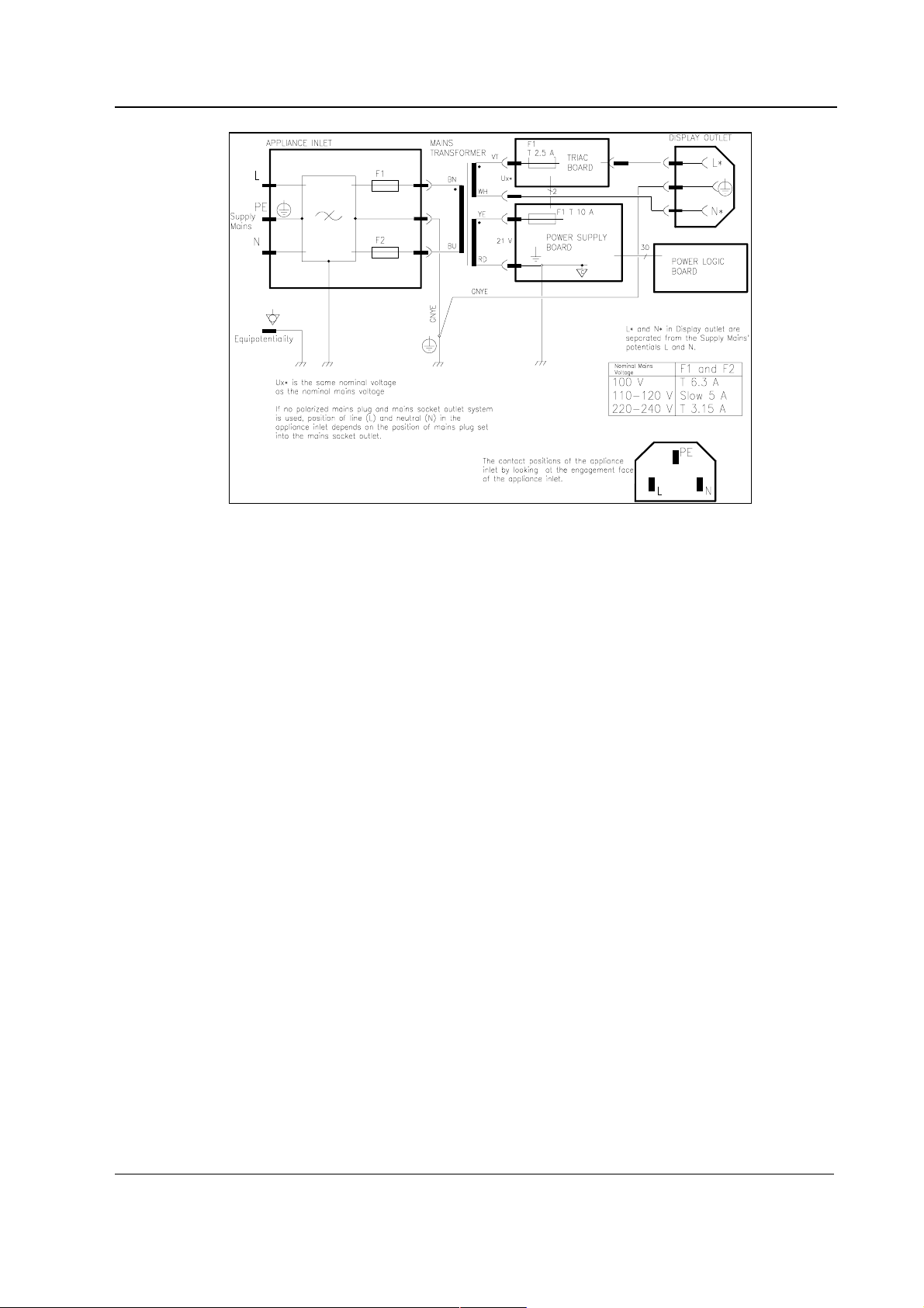
Figure 4 Mains part and display outlet block diagram
8-Module Frame, F-CU8 (Rev. 07)
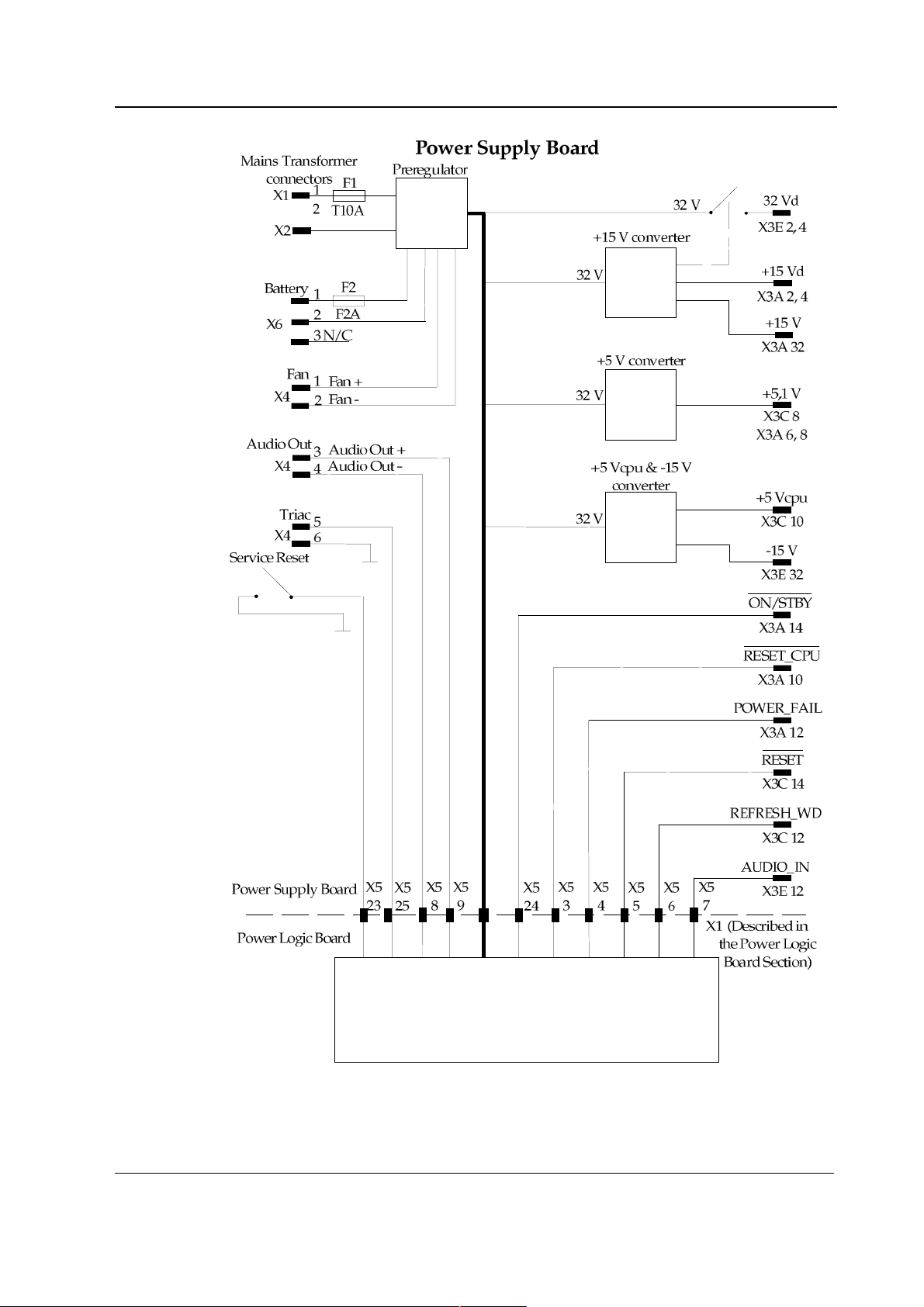
Power supply board
Rectifiers
Rectifiers processes 21 VAC from the mains transformer.
Power factor correction
Power factor correction is performed in a preregulator. The regulator modifies output current from
sinusoidal power lines into sinusoidal form. Its purpose is to boost efficiency of the mains
transformer.
Battery charging
Batchrg charges the 6 V battery which maintains the supply voltage of CPU for 15 minutes after the
power is cut off. The battery is charged as long as the power cord is connected to the mains outlet.
Supply voltage for pulse width modulators
Supply voltage for pulse width modulators of chopper power supplies is generated by 12 V
regulator at power-up and if +15 V is short-circuited. Otherwise the supply voltage comes
from +15 V.
-15 V converter
-15 V converter is a Flyback-type chopper power supply that generates -15 V analog voltage from
+32 V. The load capacity is 500 mA (7.5 W). +5 Vcpu is also generated in this converter.
5
Document No 8001003-2
Page 10

Datex-Ohmeda S/5 AM and S/5 CCM
+15 V converter
+15 V converter is a Buck-type chopper power supply that generates +15 V from +32 V.
The output of the power supply is divided into two; +15 Va for analog voltage and +15 Vd for less
sensitive components.
+5 V converter
+5 V converter is a Buck-type chopper power supply that generates +5.1 V from +32 V. The load
capacity is 8 A (40 W).
+5 V, +15 V, +32 V, and +5 Vcpu checking
Those voltages are checked and if one of them increases more than is allowed, thyristor pulls the
rectified +32 V down.
Service reset button
Service reset button is for service purpose. Press this button with an appropriate tool for at least
five seconds before you remove any PC board or the Power supply unit from the rear of the Central
Unit.
Before connecting the power cord back and start monitoring, be sure that at least one minute has
passed after the service reset button has pressed. Too short time may lead to memory flaw.
Audible alarm for power fail
Under the cover plate of the Power supply unit there are two dip switches. By turning the switches
to the left the audio alarm is activated. When mains power fails the audio alarm is generated by the
lead-acid battery.
6
Document No. 8001003-2
Page 11
8-Module Frame, F-CU8 (Rev. 07)
Figure 5 Power supply board block diagram
7
Document No 8001003-2
Page 12

Datex-Ohmeda S/5 AM and S/5 CCM
Power supply board interface to CPU mother board
Pin c2,c4: +32 Vd
Rectified and filtered +32 V dirty voltage. This voltage is switched on by pulses of +15 V chopper
power supply which turns the switching transistor on with the help of charging pump. The switching
transistor is a short-circuit protected MOSFET. The ripple voltage when fully loaded is about 3 Vpp
at the frequency of two times mains frequency.
Pin c32: -15 V
Accuracy of -15 V is ±2 %. The load capacity is 500 mA and the ripple voltage about 30 mVpp at
the chopper frequency (200 kHz ±10 %).
Pin c22: f (-15 V)
The chopper frequency measured at the rear panel connector whose pulse ratio corresponds to the
pulse width modulator's pulse ratio. For test use only.
Pin c20: st (-15 V)
Pin a2,a4: +15 Vd
Pin 32: +15 Va
Pin b22: f (+15 V)
Pin b20: st (+15 V)
The chopper can be turned off by connecting this line at the rear panel connector to ground. For
test use only.
Accuracy of +15 V is ±2 %. The load capacity is 6.5 A if +15 Va is not loaded. The ripple voltage
about 50 mVpp at the chopper frequency (200 kHz ±10 %).
+15 V for analog voltage. The load capacity is 1.2 A and is passive filtered from +15 Vd. The ripple
voltage about 10 mVpp at the chopper frequency (200 kHz ±10 %).
The total load capacity of +15 Va and +15 Vd is about 6.5 A (97.5 W).
The chopper frequency measured at the rear panel connector whose pulse ratio corresponds to the
pulse width modulator’s pulse ratio. For test use only.
Pin a6,a8,b8: +5 V
8
Document No. 8001003-2
The chopper can be turned off by connecting this line at the rear panel connector to ground. For
test use only.
Nominal voltage is 5.1 V and its accuracy is ±2 %. The load capacity is 8 A. The ripple voltage
about 50 mVpp at the chopper frequency (200 kHz ±10 %).
Page 13

Pin a22: f (+5 V)
Pin a20: st (+5 V)
Pin b10: +5 Vcpu
Pin b14: -RESET
8-Module Frame, F-CU8 (Rev. 07)
The chopper frequency measured at the rear panel connector whose pulse ratio corresponds to the
pulse width modulator's pulse ratio. For test use only.
The chopper can be turned off by connecting this line at the rear panel connector to ground. For
test use only.
Supply voltage for the CPU. Nominal voltage is 5.1 V. The accuracy is ±2 % and the load
capacity 1 A. The ripple voltage is 50 mVpp. The +5 Vcpu is connected to linearly regulated battery
voltage when the choppers are switched off.
Signal for the digital boards.
Pin a10: -RESET CPU
Signal for the CPU.
Pin a12: -POWERFAIL
The signal informs about supply voltage failure to the CPU.
Pin b12: WD
Watchdog input signal. The CPU must toggle WD within every 1.6 seconds. Otherwise the power
supply will generate -RESET and -RESET CPU signals.
Pin c12: AUDIOin
Audio signal which is amplified in Audio-amp. circuit.
Ground
All the signals and lines within the Power supply unit share the common ground which is connected
to monitor chassis.
Document No 8001003-2
9
Page 14

Datex-Ohmeda S/5 AM and S/5 CCM
Power logic board
Figure 6 Power logic board block diagram
Protections
These following protections generate automatic power off situations without any message in
advance.
1. High voltage protection (+32 V, +15 V, +5 V, +5 Vcpu). Requires manual start-up and power
2. Low voltage protection (+32 V). Automatic power off when U < +25 V. Automatic start-up
3. High current protection (all secondary outputs). Output restrained until cause is eliminated.
4. High temperature protection. Automatic power off at +58 °C (approx.) and automatic start-
Power ON/STBY control
Power ON/STBY control includes a logic with which power supply is switched on or off by turning
ON/STBY switch.
cord must be disconnected for a while. Valid from revision 03.
after voltage back to normal.
up at +54 °C (approx.). Possible caused by fan failure, fan filter is not clean or power supply
unit is overloaded. The measurement is located on the Power logic board.
10
Document No. 8001003-2
Page 15

Reset
Audio amp.
CPU interface
Display control
8-Module Frame, F-CU8 (Rev. 07)
-RESET_CPU signal is transmitted to the CPU interface in case the mains voltage fails or the power
is cut off.
-RESET signal is also generated for other digital boards.
Audio signal from the CPU is amplified and filtered for the loudspeaker. Amplification gain is about
5 dB.
All the necessary communications between the Power supply unit and the CPU (Reset-, powerfail-,
and watchdog-functions) are realized in this board. Additionally, the block contains a circuit that
supervises the maintenance of CPU’s supply voltage from the battery for 15 minutes after monitor
is turned off.
Display control circuit controls Triac board control signal (TRIAC).
Triac board
Tasks of the Triac board are to supply voltage to the Video display when the monitor is turned on
and cut off the voltage when it is turned off. This is done by a solid state relay and peripheral
components.
External components
Transformer
The power of the mains transformer is 250 VA. The secondary voltage is 21 VAC and for the display
unit it is either 100 VAC, 115 VAC, or 230 VAC.
Depending on the voltage in use, there are three different transformers for the monitor.
Fan
The fan is switched on automatically when +32 Vd is generated.
Loudspeaker
Battery
The loudspeaker is controlled by the audio-amplifier on the Power logic board.
6 V, 1.2 Ah sealed lead-acid battery is used to supply power to the CPU board after the power is
turned off and the power cord is disconnected.
11
Document No 8001003-2
Page 16

Datex-Ohmeda S/5 AM and S/5 CCM
2.1.2 CPU mother board
The CPU mother board connects the CPU board and other boards (e.g. UPI4 and Display controller
board) and functions as a bus between them.
There are connectors for six PC boards. Five of those are normally occupied (B-UPI4(NET), B-CPU4,
B-DISP and B-GAS or B-INT) and one is reserved for, e.g. Keyboard interface board, B-ARK. The bus
structure is the same in all S/5 monitors.
ON/STBY-line is connected only to a Display controller board connector from where it goes directly
to Keyboard and ON/STBY switch. The CPU mother board is connected to module mother board by
25-pin D-connector.
2.1.3 Module mother board
This board connects the modules and the main frame together electrically. Module bus structure is
the same in all S/5 monitors. There are connectors for 4 double-width or 8 single-width modules.
2.2 Connectors and signals
2.2.1 Internal connectors
Power supply (X3) - CPU mother board connector
Pin a(a) b(c) c (e)
2 +15 VD GND +32 VD
4 +15 VD GND +32 VD
6 +5 V GND GND
8 +5 V +5 V GND
10 RESET_CPU +5 V_CPU GND
12 POWER_FAIL REFRESH_WD1 LOUDSPEAKER
14 ON/STBY RESET N/C
16 N/C N/C N/C
18 GND GND GND
20 TEST1 N/C TEST2 N/C TEST3 N/C
22 TEST4 N/C TEST5 N/C TEST6 N/C
24 TEST7 N/C TEST8 N/C TEST9 N/C
26 GND GND GND
28 BAT_ON N/C V_BAT N/C I_BAT N/C
30 N/C GND N/C
32 +15 V GND -15 V
12
Document No. 8001003-2
Page 17

CPU mother board - Module mother board
Pin No I/O Signal
1 O RESET_RS485
2 O -15 VDC
3 O +15 VDIRTY
4 O +15 VDC
5 O -DATA_RS485
6 O DATA_RS485
7 O Ground & Shield
8 O -RESET_RS485
9 I CTSB
10 O RTSB
11 I RXDB
12 O TXDB
13 O Ground & Shield
14 O +32 VDIRTY
15 O GroundDIRTY
16 I CTSC
17 O RTSC
18 I RXDC
19 O TXDC
20 I ON/STANDBY
21 I PWM_ECG
22 I RXDD_RS232
23 O TXDD_RS232
24 O +5 VDC
25 O +5 VDC
8-Module Frame, F-CU8 (Rev. 07)
13
Document No 8001003-2
Page 18

Datex-Ohmeda S/5 AM and S/5 CCM
CPU bus - CPU mother board
ab c
1 +15 V AGND DGND
2 -15 V BALE DGND
3 SA0 SA1 DGND
4 SA2 SA3 RESET_RS485
5 SA4 SA5 -RESET_RS485
6 SA6 SA7 DATA_RS485
7 SA8 SA9 -DATA_RS485
8 SA10 SA11 TXDD_RS232
9 SA12 SA13 RXDD_RS232
10 SA14 SA15 PWM_ECG
11 SA16 SA17 BIT1IN
12 SA18 SA19 TXDC
13 SA20 SA21 RXDC
14 SA22 SA23 RTSC
15 -SMEMR -SMEMW CTSC
16 -SIOR -SIOW TXDB
17 CLK -RESET RXDB
18 -IOCHRDY IRQ10 RTSB
19 N/C_1 IRQ11 CTSB
20 N/C_2 IRQ12 TXDA
21 -SBHE IRQ15 RXDA
22 SD0 SD1 RTSA
23 SD2 SD3 CTSA
24 SD4 SD5 AUDIO_OUT
25 SD6 SD7 +5 V
26 SD8 SD9 +5 V
27 SD10 SD11 +5 V
28 SD12 SD13 +5 V
29 SD14 SD15 ON/STBY
30 +15 VD -RESET_CPU +5 V_CPU
31 +15 VD +32 VD REFRESH_WD
32 GNDD GNDD POWER_FAIL
14
Document No. 8001003-2
Page 19

8-Module Frame, F-CU8 (Rev. 07)
3 SERVICE PROCEDURES
3.1 General service information
Field service of the F-CU8 is limited to replacing the faulty printed circuit boards or mechanical
parts. The printed circuit boards should be returned to Datex-Ohmeda for repair.
Datex-Ohmeda is always available for service advice. Please provide the unit serial number, full
type designation, and a detailed description of the fault.
CAUTION Only trained personnel with appropriate equipment should perform the tests and
repairs outlined in this section. Unauthorized service may void warranty of the unit.
3.2 Service check
These instructions include complete procedures for a service check. The service check is
recommended to be performed after any service repair. However, the service check procedures can
also be used for determining possible failures.
The procedures should be performed in ascending order.
The instructions include a check form (Appendix A) which should be filled in when performing the
procedures.
The mark
the procedure.
The procedures are designed for monitors with software of level 00. However, most of the
procedures also apply to monitors with older monitor software.
? in the instructions means that the check form should be signed after performing
3.2.1 Recommended tools
Tool Order No. Notes
Command Board
M-REC
M-NE(12)STPR/M-ESTPR/M-ESTP
Datex-Ohmeda gas monitor e.g. Capnomac Ultima
UPI Interface cable 887245
Multimeter
Screwdriver
3.2.2 Recommended parts
Part Order No. Notes
Fan filter 871558
Recorder paper
15
Document No 8001003-2
Page 20

Datex-Ohmeda S/5 AM and S/5 CCM
General
Make sure that no cables and modules are connected to the Central Unit. Lift off the Video display
with its stand, if placed on the Central Unit.
8-Module Frame, F-CU8
1. Check that the central unit plastic frame is intact.
?
2. Check that the two brass plugs on the frame are tightened properly.
?
3. Turn the frame onto one of its sides. Check that all the four rubber pads are in place and the
screws on the bottom are tightened properly.
?
4. Check that the loudspeaker is intact.
Power supply unit
?
5. Turn the frame back on to its normal position.
Check that the module motherboard connectors are clean and intact. Check also that the
screws that connect the module mother board to the frame are tightened properly.
?
6. Check that the M-REC fits in smoothly and locks up properly in all possible slots in the
Central Unit. Leave the M-REC disconnected.
?
7. Clean or replace the fan filter.
?
8. Disconnect the primary fuse holder. Check that the fuse compartment, the fuse holder and
the fuses are clean and intact. Check also that the fuses are of the correct rating.
Reconnect the fuse holder and check that it locks up properly.
?
16
Document No. 8001003-2
9. Check that the connectors for the mains power cord and display power cord are clean and
intact.
?
Page 21

PC boards
8-Module Frame, F-CU8 (Rev. 07)
10. Check that the service reset -switch is intact. Press the switch at least for five seconds.
?
11. Check that the equipotential tap and all the rear panel screws are tightened properly.
?
12. Check that all the rear side PC boards are secured to the Central Unit with two screws.
?
13. Check that the PC boards rear panel connectors are clean and intact.
?
14. Check that all block screws for cables are in place and are tightened properly. Check also that
their threads are intact.
?
15. Check that the grounding plates under the PC board rear panels are attached properly and
are not bent.
NOTE: Older PC boards may not include the grounding plates.
?
16. If the Central Unit has the B-GAS or the B-INT installed, disconnect the board and check that
the fuse and its holder are clean and intact. Check also that the fuse is of the correct rating.
NOTE: The B-GAS may include up to six fuses. All fuses and their holders should be checked.
Leave the board disconnected.
?
17. Disconnect the Display controller board(s) and check that the address and interruption
jumpers have been set correctly. The instructions for setting the jumpers can be found in the
Technical Reference Manual.
Leave the board(s) disconnected.
?
Disconnect the UPI4(NET) board.
17
Document No 8001003-2
Page 22

Datex-Ohmeda S/5 AM and S/5 CCM
General
18. Measure resistance from the following Module mother board connector pins against the
ground:
Pin 1 +Reset RS485
Pin 5 -Data RS485
Pin 6 +Data RS485
Pin 8 -Reset RS485
Pin 13 Ground
13
25
14
1
Module mother board connector
Check that the resistance on each of the pins is higher than 10 kΩ. If not, exchange the
Module mother board.
?
• Reconnect the PC boards and secure them to the Central Unit with screws.
• Install the video display together with the Command Board, the M-NE(12)STPR/M-
ESTPR/M-ESTP and the M-REC. Connect the mains power cord and turn the monitor on.
19. Check that the fan is running.
?
20. Check that the monitor starts up properly, i.e. the alarm LEDs on the Command Bar turn
blank, the start-up sound is heard from the loudspeaker and the normal monitoring screen
appears. No error messages should appear onto the screen.
?
21. Check that the connected modules are recognized, i.e. the needed parameter information is
shown on the screen and the M-REC records two lines of start-up information.
If some parameter information is missing, check the screen configuration from the
MONITOR SETUP -menu.
?
18
Document No. 8001003-2
22. Check that the clock on the screen shows correct time. Adjust the time, if necessary.
Monitor Setup - Time And Date
NOTE: If the clock shows time 0:00 continuously (at successive start-ups), the
SRAM/TIMEKEEPER chip on the CPU board, or its battery, is need to be replaced.
The FACTORY RESET should be performed after the made replacement.
?
Page 23

8-Module Frame, F-CU8 (Rev. 07)
23. Check the loudspeaker by setting the alarm sound:
Alarms Setup - Alarm Volume
Test the whole volume scale from 1 to 10 by turning the ComWheel and check that the
alarm volume changes correspondingly. The alarm sound should be clear and audible with
all the settings.
?
24. Enter the service menu.
Monitor Setup - Install/Service (password 16-4-34) - Service (password 26-23-8)
Take down the information regarding monitor software.
?
25. Select SERVICE LOG from the menu. Record the Service log onto the M-REC by selecting
RECORD LOG. Check the content of recording for possible problems, then empty the Service
log by selecting RESET LOG from the menu.
?
26. Check the power supply unit output voltages through the service menu:
Monitor Setup - Install/Service (password 16-4-34) - Service (password 26-23-8) -
Frame - Power Supply
The output voltages should meet the following ranges:
Raw DC
31.0...33.0 V (F-CU8 Rev. 03-04)
22.0...26.0 V (F-CU8 Rev. 01-02)
+15V 14.20…..15.60 V
-15V -14.00...-15.50 V
+15VD 14.10.….15.60 V
+5V 4.70...…5.40 V
+5Vcpu 4.70….. 5.40V
Connector X2
If any of the voltages is out of the tolerance, replace the Power supply board.
?
27. Test the Central Unit watchdog circuitry:
Monitor Setup - Install/Service (password 16-4-34) - Service (password 26-23-8) Set/Test - Watchdog
Go through the tests one by one and check that the monitor performs a restart in all other
cases except when performing WD by UPI.
NOTE: When selecting WD BY OVERLOAD, restarting should take place approximately after
15 seconds. With the other tests restarting takes place within a couple of seconds.
Document No 8001003-2
19
Page 24

Datex-Ohmeda S/5 AM and S/5 CCM
If restarting did not take place, try to locate the fault:
Watchdog --> CPU board /Power supply unit
WD by Overload --> CPU board
WD by GSP --> Primary display controller board / CPU board
?
28. Check that the monitor is capable of storing the trend information and temporary settings in
a short (max. 15 minutes) standby.
Turn the monitor to standby and disconnect the power cord. Wait for two minutes, then
reconnect the power cord and turn the monitor back on. The monitor should perform a
“Warm start” which means the trend information and temporary settings should still be
available.
If the monitor performed a “Cold start” instead, the battery fuse or the battery is need to be
replaced.
NOTE: The B-CPU2/3/4 require 2 Amps battery fuse (P/N 51063).
The information regarding a start-up is saved also in the Service log.
?
29. Check the service reset -switch. Turn the monitor to standby and press the service reset -
switch at least for five seconds. Turn the monitor back on and check that the monitor
performs a “Cold start”.
?
30. Disconnect the power cord (during operation) for a moment, reconnect it and check that the
monitor recovers without problems. The monitor should perform a “Warm start”.
NOTE: F-CU8 Rev. 03 may give an audible alarm during the power loss. The alarm is set by
the DIP switch No. 2 on the power supply board (behind the power supply unit rear panel).
?
31. Turn the monitor off. Connect a Datex-Ohmeda gas monitor to the UPI4(NET) board using
the UPI Interface cable P/N 887245. Turn the monitors on and set the interface according
to the interfaced gas monitor:
Monitor Setup - Install/Service (password 16-4-34) - Installation - Interfacing -
Gases/Spiro SpO2 -
20
Document No. 8001003-2
Make sure that also the screen configuration is appropriate
Monitor Setup - Screen 1 Setup - Waveform Fields - Field 5 - Pleth
- FIELD 6 - CO
Check that the interfaced parameters appear onto the monitor screen.
2
Page 25

?
32. Perform an electrical safety check and a leakage current test.
?
33. Check that the Central Unit functions normally after the performed electrical safety check.
?
34. Clean the Central Unit with suitable detergent.
?
• Fill in all necessary documents.
3.3 Disassembly and reassembly
Disassemble the F-CU8 in the following way. See the exploded view of the frame.
1. Disconnect the power cord.
8-Module Frame, F-CU8 (Rev. 07)
2. Remove all the parameter modules from the front of the frame.
3. Press and hold the service reset button on the rear panel of the Power supply unit for at least
five seconds (until a soft sound is heard). After this the Power supply unit and all the PC
boards can be detached from the frame.
4. Blank connector plates and the PC boards are pulled off after removing two screws and
washers. Notice that the PC boards can be removed only in certain order.
NOTE: The B-UPI4(NET) contains components on both sides of the PCB. Therefore, the
installation of B-UPI4(NET) should be handled with extra care. Detach the board from the
frame carefully by pulling it from the X3 connector (25 pin female D-connector).
5. Remove the cross recess screw M6x30 with its support plate from the bottom of the unit.
6. Remove the two screws with star washers which are at the top of the back panel of power
supply unit.
Now the Power supply unit is free. Get hold of the equipotential connector pin and fuse housing,
and pull the unit out. Move the unit from side to side if it does not come out smoothly. Be careful
not to damage the speaker attached to the bottom of the unit.
7. Remove the screws at the module mother board and one screw from the bottom panel. The
metal chassis to which module mother board and CPU mother board are attached can be
pulled out from rear.
8. Module mother board and CPU mother board are attached to the metal chassis with screws.
These boards are connected to one another by 25-pin connector.
When reassembling, reverse the order of the disassembling steps as described before. When
inserting the metal chassis into the external frame, fasten the screws from the front before
fastening the one thick screw on the bottom panel. This way the metal chassis can be attached as
close as possible to the inner divider wall. Check that the 25 pin module connectors are exactly in
the middle of the openings for the connectors in the plastic frame.
When reinstalling PC boards, push them carefully until they stop before fastening them with
screws.
Document No 8001003-2
21
Page 26

Datex-Ohmeda S/5 AM and S/5 CCM
NOTE: When reassembling the boards set them to the slots recommended in the sticker. The
boards can only be assembled in certain order.
3.3.1 Power supply unit
The power supply unit is disassembled by removing four screws from the top cover, disconnecting
the cables between the top cover and the Power supply board and then lifting the cover off. Leadacid battery and power logic board are attached to the back of the top cover. See the exploded
view of the unit, see chapter 6 of this section.
Power supply board is attached to the bottom of chassis with three screws. Transformer,
loudspeaker, and Triac board are also attached to the bottom. Fan, mains power receptacle, and
display power outlet are attached to the rear of the chassis. Rear panel is also attached to the rear
of the chassis with three screws.
When reassembling, reverse the order of the disassembling steps as described before. When
inserting the Power supply unit back to the Central unit, make sure that the Power supply unit is
properly attached to the CPU mother board before fastening the screws.
3.3.2 Lead acid battery
The sealed lead-acid battery in the Power supply unit can be used for 3 to 5 years. If the trends are
not stored in the memory for 15 minutes after the power is turned off and the power cord is
disconnected, the fault is probably in the battery or in the battery fuse.
To change the battery: Remove the screw that holds the battery to the top cover of the power supply
unit.
When replacing the battery, make sure the + indicated battery cable is attached to the + pole of the
battery.
Dispose of the old battery according to the local regulations.
3.3.3 Changing fuses
Power supply main fuses are located next to power cord receptacle. The fuse holder can be
removed by gently pushing the locking pin above the holder (or the locking pins at both sides) and
the same time pulling the holder.
CAUTION Use only fuses with specified type and ratings.
To change the secondary fuse on the Power supply board: Remove the rear panel from the power
supply unit by removing the two screws at the top and two screws at the bottom of the panel.
Replace the fuse placed on the upper right corner.
3.4 Adjustments and calibrations
It is not necessary to do calibrations or adjustments to the F-CU8.
22
Document No. 8001003-2
Page 27

4 TROUBLESHOOTING
4.1 Troubleshooting flowcharts
4.1.1 Monitor
M onitor not functioning
8-Module Frame, F-CU8 (Rev. 07)
O n/S T B Y sw itch 'O N '
D isplay connected?
Keyboard connected?
P o w e r c o rd
connected?
No
C onnect pow er cord
R em ove all m odules
a n d tu rn p o w e r o n
Is fan running?
Yes
Any LEDs lit
on keyboard?
Yes
Start-up texts
appear on
screen?
Yes
Yes
No
No
OK?
No
No
No
C onnect and check
No
OK?
D isconnect and reconnect the pow er cord
Yes
OK?
No
Turn pow er on by shorting
13 (G ND) and 20 (O N/STBY)
at G as Interface board connector
Is fan running?
Yes
Keyboard trouble. S ee part II
for troubleshooting.
Yes
The pow er supply unit
w as shut dow n by instant over
voltage in the m ains.*)
*) N O T E ! In c a s e o f s h o rt p o w e r o ff
and autom atic start-up see section
"P ow er logic board/P rotections" to find
possible reason.
No
C lock etc
appears on
the scre en?
Yes
Plug in a m odule
M odule data
appear on
the scre en?
No
Yes
Pick up next
m odule
Faulty C entral U nit. G o to
No
next page.
A nother
m odule w orks
in sam e place?
No
C h e c k o th e r
positions w ith sam e
m o d u le , W o rk ?
Figure 7 Monitor troubleshooting flowchart
Yes
Faulty m odule. G o to M odule
troubleshooting.
Yes
Faulty m odule m other board
F a u lty C e n tra l U n it, g o to
No
next page.
23
Document No 8001003-2
Page 28

Datex-Ohmeda S/5 AM and S/5 CCM
4.1.2 Central Unit
Central Unit faulty
Check mains fuses.
Does Ce ntral Unit work?
Check fuses on Power
Supply Board.
Does Ce ntral Unit work?
Disconnect mains power cord.
Remove all plug-in modules.
Disconnect Airway module.
Disconnect Command board.
Connect mains power cord and
turn power on by shorting pins
13 (GND) and 20 (ON/STBY) at
Gas interface board connector.
No
No
Yes
Remove Power supply unit and
turn it on by shorting pins a14
(ON/STBY) and a18 (GND). See
chapter 2.4.1 connector X3 .
Is fan
running?
No
Is fan
running?
No
Are
power supply
voltages
OK?*
No
Power supply board/unit
faulty. Replace it.
Yes
Yes
CPU mother board or Gas
interface board faulty.
Check continuities of ground
and ON/STBY line through to
Command board.
Digital section faulty. Go to
"Digital section troubleshooting
chart".
* see 2.4.1 connector x3
5V
5V CPU
+15 V
- 15 V
+32 V
24
Document No. 8001003-2
Figure 8 Central Unit troubleshooting flowchart
Page 29

4.1.3 Digital section
Digital section faulty.
Remove all modules and boards
except CPU, UPI and display
controller board
Insert one of the removed
boards.
Replace faulty board
Turn
the monitor on.
OK ?
Yes
Turn
the monitor on.
OK ?
No
No
Yes
A
beep is
heard when
monitor is
turned
on ?
Yes
Is tone
same as at
OK start ?
No
Is tone
same as at
OK start but
longer ?
No
8-Module Frame, F-CU8 (Rev. 07)
No
Replace CPU board.
Yes
Try with another display
OK?
No
Yes
Replace Display controller.
Yes
Replace display
Is tone
lower and longer
than at OK
start ?
Yes
Figure 9 Digital section troubleshooting flowchart
Replace UPI-board
25
Document No 8001003-2
Page 30

Datex-Ohmeda S/5 AM and S/5 CCM
T
5 SERVICE MENU
The monitor has Service menu, which is a useful tool to examine monitor functions and to
troubleshoot in case a fault occurs.
5.1 Service menu structure
Service Menu
Frame
Set / Test
Display
Keyboard Keyboard Type
Parameters
Memory
Communication
Network Comm.
Network Status
MemCard Comm.
MemCards Status
DIS Interfacing
Power Supply Battery
Keyboard Log
Gas Unit
ECG
STP
P/PT
PP
COP
Analog Outputs
26
Document No. 8001003-2
Ventilator
Service Log
Record Data
Remote Access
NIBP
NMT
M-NSAT
More . . .
Error History
Event History
Alarm History
Interface
EEG
ONO
Maintenance
Planned Maint.
Repair
Upgrade
Page 31

5.2 Service
8-Module Frame, F-CU8 (Rev. 07)
1. Press the Monitor Setup key.
2. Select Install/Service (password 16-4-34).
3. Select Service (password 26-23-8).
27
Document No 8001003-2
Page 32

Datex-Ohmeda S/5 AM and S/5 CCM
5.3 Service menu
The field on the right shows software versions and their release dates of different parts of the
monitor, control numbers of measuring boards and serial numbers of modules (if available).
Scroll Vers enables to scroll the field on the right side.
‘-More-’ indicates that there are more lines to be viewed.
Record Vers
By choosing this selection, the software versions and
other information are printed to the device defined in the
Record Data menu.
5.4 Frame
The frame menu includes service menus common for the
frame.
28
Document No. 8001003-2
Page 33

5.4.1 Power Supply
The menu shows voltages and temperature measured by
the UPI4(NET) board. The measurement starts about 100
ms after a start-up. The values in the column under Mean
are the mean values of last one second, the Min column
shows the minimum mean value, and Max column the
maximum mean value of the voltages and temperature
measured during the current power ON.
The voltages should meet the following ranges:
Raw DC
31.0...33.0 V, (F-CU8, rev. 03-04)
22.0...26.0 V, (F-CU8, rev. 01-02
+15V 14.20….15.60
–15V -14.00...-15.50 V
+15VD 14.10...15.60 V
+5V 4.70...5.40 V
+5Vcpu 4.70...5.40 V
Temp (° C) value corresponds with the Central Unit
internal temperature measured at the location of
UPI4(NET) board.
The numbers on this page are only directive and not
absolute values.
8-Module Frame, F-CU8 (Rev. 07)
29
Document No 8001003-2
Page 34

Datex-Ohmeda S/5 AM and S/5 CCM
6 SPARE PARTS
6.1 Spare parts list
NOTE: Only changed part numbers are listed under later revisions. To find the desired part: check
first the list of the revision that corresponds your device. If the part is not listed there, check the
previous revision, etc. until you find the right number.
6.1.1 8-Module Frame, F-CU8 rev. 01
Item Description Order no. Item Description Order no.
- Block screw for cables 546096 9 Frame 879097
- Fan filter *871558 10 Cross cylinder head screw M5x8 61516
1 Bronze tap for display screen tray 879476 11 Pad 65144
2 CPU mother board, AS/3 AM (Rev. 01-02) 880319 12 Rail for PC boards 879257
3 Module mother board, AS/3 AM (Rev. 01-02) 880320 13 Connector plate, blank/wide 880278
4 UPI board, AS/3 AM (Rev. 01) *(880321)
Use 890356
5 Metal box, F-CU8 (Rev. 01-02) 880349 15 Cross cylinder head screw M3x8 61722
6 Connector plate, blank/narrow 879393 16 Service Reset Switch, AS/3 AM (Rev. 01-02) 881378
7 Power supply unit, AS/3 AM (-21-) (Rev. 01-02) *884588 17 Cross recess screw M6x30 61673
7 Power supply unit, AS/3 AM (-23-) (Rev. 01-02) *884589 18 Support plate for 61673 879502
7 Power supply unit, AS/3 AM (-28-) (Rev. 01-02) *884590 - - -
*this part is recommended for stock
30
Document No. 8001003-2
14 Star washer M3.2 63611
Page 35

8-Module Frame, F-CU8 (Rev. 07)
Item Description Order no. Item Description Order no.
19 Power supply unit top cover,
(Rev. 01-02)
20 Fan, AS/3 AM 880049 29 Display power outlet 54027
22 Loudspeaker,
AS/3 AM, (Rev. 01-02)
23 Fuse Miniature T1A *51062 32 Triac board,
24 Power supply board,
AS/3 AM, (Rev. 01-02)
25 Fuse T6.3A *51128 33 Fuse T2.5A (USA) *511181
26 Power supply unit chassis,
AS/3 AM (Rev. 01-02)
27 Mains power receptacle 54014 34 Transformer (220-230 V) 26135
28 Fuse T3.15A *51119 34 Transformer (230-240 V) 26134
880351 28 Fuse 5A slow (USA) *511382
880048 30 Lead-acid battery 17006
*(880317)
AS/3 AM (Rev. 01-02)
*(880316) Use
885334
879254 34 Transformer (110-120 V) 26133
33 Fuse T2.5A *51118
Use 887364
Document No 8001003-2
31
Page 36

Datex-Ohmeda S/5 AM and S/5 CCM
6.1.2 8-Module Frame, F-CU8 rev. 02
Item Description Order no.
4 UPI board, AS/3 AM (Rev. 02-03) *(882354) Use 890356
6.1.3 8-Module Frame, F-CU8 rev. 03
Item Description Order no.
- Grounding plate for UPI board 885399
2 CPU mother board, AS/3 AM (Rev. 03) (882953) Use 891585
3 Module mother board, AS/3 AM (Rev. 03) *882954
5 Metal box, F-CU8 (Rev. 03) 882501
6 Connector plate, blank/narrow 885389
7 Power supply unit, AS/3 AM (-22-) (Rev. 03) *884591
7 Power supply unit, AS/3 AM (-28-) (Rev. 03) *884592
7 Power supply unit, AS/3 AM (-31-) (Rev. 03) *884593
13 Connector plate, blank/wide 885394
16 Service Reset Switch, AS/3 AM (Rev. 03) 52090
19 Power supply unit top cover, AS/3 AM (Rev. 03) 882336
21 Ribbon cable 882520
22 Loudspeaker, AS/3 AM (Rev. 03) 882509
23 Fuse Miniature 2AF *51063
24 Power supply board, AS/3 AM (Rev. 03) *882507
25 Fuse T10A 250 V *51137
26 Power supply unit chassis, AS/3 AM (Rev. 03) 882337
27 Mains power receptacle 540140
28 Fuse T6.3A (JPN) *51128
31 Power logic board, AS/3 AM (Rev. 03) *882508
32 Triac board, AS/3 AM (Rev. 03) *(884185) Use 887364
34 Transformer (100-105 V) 26139
34 Transformer (110-120 V) 26138
34 Transformer (220-240 V) 26137
36 Grounding plate, blank/narrow 885398
37 Grounding plate, blank/wide 885404
6.1.4 8-Module Frame, F-CU8 rev. 04
Item Description Order no.
2 CPU mother board, AS/3 AM/CCM (Rev. 04) 891585
4 UPI board, AS/3 AM/CCM (Rev. 04) *890356
6.1.5 8-Module Frame, F-CU8 rev. 05
Item Description Order no.
9 Frame 892823
32
Document No. 8001003-2
Page 37

8-Module Frame, F-CU8 (Rev. 07)
6.1.6 8-Module Frame, F-CU8 rev. 06
Item Description Order no.
9 Frame 898314
6.1.7 8-Module Frame, F-CU8 rev. 07
No new spare parts.
33
Document No 8001003-2
Page 38

Datex-Ohmeda S/5 AM and S/5 CCM
7 EARLIER REVISIONS
This service manual fully supports earlier revisions except,
Item Manual and document number
8-Module Frame, F-CU8 (rev 01/rev.02) Service Manual, 880 850
CPU Board, B-CPU1 (rev 01) Service Manual, 882 580
Software Cartridge, S-STD/S-STD93 Service Manual, 882 580
Software Cartridge, S-STD94/S-ARK94 Service Manual, 885 930
Software Cartridge, S-STD95/S-ARK95 Service Manual, 885 930
Software Cartridge, S-STD96/S-ARK96 Service Manual, 885 931
Service Menu descriptions related to softwares of level 97/98 Technical Reference Manual Slot 895 704
34
Document No. 8001003-2
Page 39

APPENDIX A, Service check form,Central Unit
APPENDIX A
35
Document No. 8001003-2
Page 40

Datex-Ohmeda S/5 AM and S/5 CCM
36
Document No. 8001003-2
Page 41

SERVICE CHECK FORM
8-Module Frame, F-CU8
Customer
APPENDIX A, Service check form,Central Unit
Service
Service engineer Date
OK = Test OK N.A. = Test not applicable Fail = Test Failed
OK N.A. Fail OK N.A. Fail
1. Frame 2. Brass plugs
3. Pads and screws 4. Loudspeaker
5. Module motherboard
connectors
7. Fan filter 8. Primary fuses
9. Power connectors 10. Service reset -switch
11. Equipotential tap and
screws
13. PC board connectors 14. Block screws for cables
Frame revision S/N
6. Module motherboard
position
12. PC board screws
15. Grounding plates 16. B-GAS/B-INT fuse(s)
17. Display controller
board jumpers
Notes
18. Communication lines
+Reset RS485 (pin 1) > 10 kΩ
-Data RS485 (pin 5)
+Data RS485 (pin 6)
-Reset RS485 (pin 8)
> 10 kΩ
> 10 kΩ
> 10 kΩ
Document No. 8001003-2
A-1(2)
Page 42

Datex-Ohmeda S/5 AM and S/5 CCM
OK N.A. Fail OK N.A. Fail
19. Fan 20. Starting
21. Module
22. Real time clock
communication
23. Loudspeaker sound
24. Monitor software
S-
23. Content of service log
26. Voltages
Raw DC, F-CU8 rev. 03-> 31.0...33.0 V
Raw DC, F-CU8 rev. 01-02 22.0...26.0 V
+15 V 14.20...15.60 V
-15 V -14.00...-15.50 V
+15 VD 14.10...15.60 V
+5 V 4.70...5.40 V
+5 Vcpu 4.70...5.40 V
OK N.A. Fail OK N.A. Fail
27. Watchdog circuitry 28. Trend retaining
29. Service reset switch 30. Recovering from power
loss
31. UPI board interface
Notes
32. Electrical safety check 33. Functioning after
electrical safety check
34. Final cleaning
Notes
Used Spare Parts
Signature
A-2(2)
Document No. 8001003-2
 Loading...