

Page 1

Datex-Ohmeda
S/5™ CPU Board, B-CPU4 (Rev. 01)
CPU Board, B-CPU3 (Rev. 00)
CPU Board, B-CPU2 (Rev. 01)
Software Cards
Technical Reference Manual Slot
Datex-Ohmeda, Inc.
P.O. Box 7550, Madison
WI 53707-7550, USA
Tel. 1-608-221-1551 Fax 1-608-222-9147
mailto:product.support.ussub@us.datex-ohmeda.com
www.us.datex-ohmeda.com
All specifications are subject to change without notice.
Document No.8002818-1
December 2001
Datex-Ohmeda Division,
Instrumentarium Corp.
P.O. Box 900, FIN-00031
DATEX-OHMEDA, FINLAND
Tel. +358 10 394 11 Fax +358 9 146 3310
www.datex-ohmeda.com
Instrumentarium Corp. All rights reserved.
Page 2

Page 3

Table of contents
TABLE OF CONTENTS
CPU boards and softwares
TABLE OF CONTENTS i
Introduction 1
1 Specifications 2
1.1 Electrical requirements .............................................................................................................................2
1.2 Environmental requirements .....................................................................................................................2
2 Functional Description 3
2.1 CPU board, B-CPU4 ..................................................................................................................................3
2.2 CPU board, B-CPU2/B-CPU3 ....................................................................................................................5
2.3 Software Card, L-ANE01S, L-ANE01AS, L-ICU01S, L-ICU01AS ...................................................................7
2.4 Software Card, S-00A01S, S-00A02S, S-00C01S, S-00C02S, L-00A03 ....................................................8
2.5 Software Card, S-ANE98S, S-ARK98S, S-ICU98S ......................................................................................8
2.6 Software Cartridge, S-ANE97, S-ARK97, S-ICU97 ......................................................................................8
2.7 Connectors and signals.............................................................................................................................9
2.7.1 Internal connectors...........................................................................................................................9
3 Service Procedures 11
3.1 General service information.....................................................................................................................11
3.2 Service check .........................................................................................................................................11
3.2.1 Recommended tools ......................................................................................................................11
3.3 Disassembly and reassembly..................................................................................................................14
3.3.1 Loading/replacing software on CPU Board, B-CPU4.........................................................................15
3.3.2 Performing Factory Reset ................................................................................................................16
3.4 Adjustments and calibrations..................................................................................................................16
4 Troubleshooting 17
4.1 Troubleshooting flowcharts......................................................................................................................17
4.1.1 Monitor..........................................................................................................................................17
4.1.2 Digital section................................................................................................................................18
4.1.3 Software Card ................................................................................................................................19
4.2 Error messages.......................................................................................................................................20
5Service menu 21
5.1 Service menu structure ...........................................................................................................................21
5.1.1 Service menu structure in S-xxx98(S) software and earlier ................................................................22
5.2 Service...................................................................................................................................................23
5.3 Service menu .........................................................................................................................................24
5.4 Frame ....................................................................................................................................................24
5.4.1 Memory .........................................................................................................................................25
5.4.2 Communication..............................................................................................................................25
5.5 Parameters.............................................................................................................................................26
5.6 Set/Test.................................................................................................................................................27
5.6.1 Country Settings.............................................................................................................................28
5.7 Service Log.............................................................................................................................................29
5.7.1 Error History ...................................................................................................................................29
Document No.8002818-1
i
Page 4

S/5 Anesthesia Monitor and S/5 Critical Care Monitor
5.7.2 Event History..................................................................................................................................30
5.7.3 Alarm History .................................................................................................................................30
5.7.4 Maintenance .................................................................................................................................31
5.8 Record Data...........................................................................................................................................33
5.9 Remote Access ......................................................................................................................................33
6 Spare Parts 34
6.1 Spare parts list.......................................................................................................................................34
6.2 Products ................................................................................................................................................34
6.2.1 CPU boards and softwares..............................................................................................................34
6.2.2 CPU Board, B-CPU1 .......................................................................................................................35
6.2.3 CPU Board, B-CPU2 rev. 00 ............................................................................................................35
6.2.4 CPU Board, B-CPU2 rev. 01 ............................................................................................................35
6.2.5 CPU Board, B-CPU3 .......................................................................................................................35
6.2.6 CPU Board, B-CPU4 .......................................................................................................................35
7 Earlier Revisions 36
APPENDIX A 37
Service check form A-1
TABLE OF FIGURES
Figure 1 B-CPU4 board......................................................................................................................................1
Figure 2 CPU board block diagram, B-CPU4 board..............................................................................................4
Figure 3 CPU board block diagram, B-CPU2/3 ...................................................................................................6
Figure 4 Monitor troubleshooting flowchart.......................................................................................................17
Figure 5 Digital section troubleshooting flowchart .............................................................................................18
Figure 6 Software Card troubleshooting flowchart .............................................................................................19
ii
Document No. 8002818-1
Page 5

INTRODUCTION
This section provides information for the maintenance and service of the following products:
• CPU board, B-CPU2/B-CPU3/B-CPU4
• Software Card L-ANE01S / L-ANE01AS / L-ICU01S / L-ICU01AS , w/ empty B-CPU4
• Software Card S-00A01S / S-00A02S / S-00C01S / S-00C02S / L-00A03S / L-00A04S,
w/ empty B-CPU4
• Software Card, S-ANE98S/S-ARK98S/S-ICU98S, w/ empty B-CPU4
• Software Cartridge, S-ANE97/S-ARK97/S-ICU97, w/ B-CPU2/3
CPU boards and softwares
Figure 1 B-CPU4 board
1
Document No.8002818-1
Page 6

S/5 Anesthesia Monitor and S/5 Critical Care Monitor
1 SPECIFICATIONS
1.1 Electrical requirements
Interruptibility Data memory and alarm settings are saved during power failures up
to 15 minutes
1.2 Environmental requirements
Operating temperature 10...35 °C / 50...95 °F
Storage temperature -10...+50 °C / 14...122 °F
Atmospheric pressure 660...1060 hPa (660...1060 mbar)
Humidity 10...90 % non-condensing
2
Document No. 8002818-1
Page 7

2 FUNCTIONAL DESCRIPTION
2.1 CPU board, B-CPU4
The CPU board takes care of the central processing.
The main features of the CPU board are:
• AMD 486DX4 or 486DX5 processor
• Internal clock frequency 75 MHz
• 16 MB DRAM
• 4 MB program flash memory
• 8 kB static RAM with real time clock
• 32 kB EEPROM memory
• 2 + 2 channels UART:
• 3 serial channels with signals in AC-logic level
• 1 serial channel signals in RS232-level
• Programmable alarm sound generator
• PC-card slot for software updates
CPU boards and softwares
Document No.8002818-1
3
Page 8
S/5 Anesthesia Monitor and S/5 Critical Care Monitor
A
CONTROL
PS2
KEYB
CONN
DAC
2 CH.
PLD
NAND
FLASH
4Mx8
ISA BUS
Buffer
BSA[0..23]
BSD[0.15]
80486
DX4/DX5
3.3V
3.3V
5V->3. 3V
REGULATOR
5V
[2..31]
D[0..31]
CONTROL
72 pin SIMM
DRAM
MODULE
16..32MB
MA,RAS,CAS
FLASH
CARD
RADISYS
R400EX
PC-ChipS et
50MHz
14.3MHz
FREQUENCY
GENERATOR
14.318
MHz
XTAL
PCMCIA
-controller
Buffer
ISA CONTROL
SD[0..15]
SA[0..1]
SD[0..15]
SA[2..23]
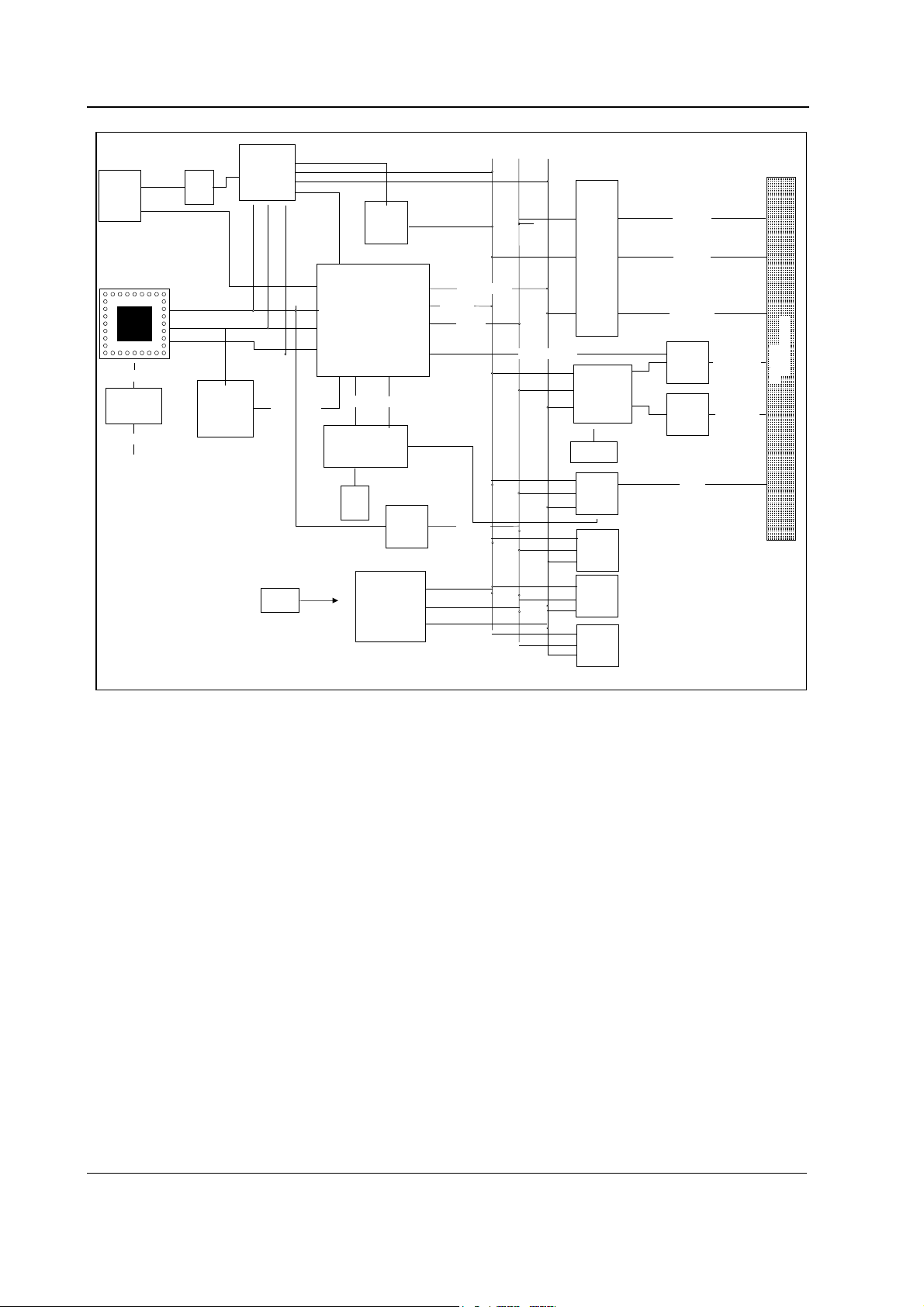
Figure 2 CPU board block diagram, B-CPU4 board
2 x serial cannel
ISA CONT ROL
SA[0..23]
DUART
7.3728MHz
XTAL
Audio
Generator
EEPROM
64Kx8
BOOT
FLASH
2Mx16
SRAM
& RTC
8kx8
BCONTROL
Buffer
TXDA..CTSC
232-Buff er TXDD..RXD
AUDIO
D
96-pin conn ector
CPU BUS
The CPU board, B-CPU4 is made with PC-technology components. Radisys chipset and PLD handle
all timings and signaling for ISA type CPU bus.
With B-CPU4 there is no external software cassette. Instead there is onboard flash memory where
software is loaded from the PC-card.
Powerfail or standby
When the monitor is turned to standby or the mains voltage fails, NMI-interrupt is generated by the
power control logic. The interrupt signal in the CPU means that all supply voltages except +5V for
the CPU board will be switched off shortly. NMI interrupt service program then saves all necessary
parameters in the static RAM before supply voltages fail.
When hardware detects HALT command generated from power down; all the outputs to the CPU
motherboard are left floating in high impedance state. Only DRAM refreshing cycle continues to
occur. The halt state will continue until a RESET pulse from the power control logic circuit is
received.
4
Document No. 8002818-1
Page 9

Watchdog functions
There are certain watchdog functions to ensure the monitor’s performance. The UPI4 board and the
primary display controller board interrupts the CPU board continuously in order to state that
everything runs smoothly. The CPU board refreshes the watchdog timer in the power supply unit in
order to prevent reset pulse. If the primary display controller board or the CPU board stops the
refreshment, the monitor will be reset in order to prevent false information to be displayed on the
screen. If the UPI4(NET) board stops the refreshment, the board will be reset internally.
SRAM M48T18
Lithium battery back-up 8 kB static RAM with a real-time clock.
CAUTION The IC contains a lithium battery. Discard the battery according
to local regulations
2.2 CPU board, B-CPU2/B-CPU3
CPU boards and softwares
.
The CPU board takes care of the central processing.
The main features of the CPU board are:
• 80486 processor
• Clock frequency 32 MHz
• Software cartridge interface
• B-CPU2, 2 MB DRAM
• B-CPU3, 8 MB DRAM
• 8 kB static RAM with real time clock
• 32 kB EEPROM memory
• 4 channel UART:
• 3 channels with modem signals in AC-logic level
• 1 channel with modem signals in RS232-level
• programmable alarm sound generator
• 5 external and 3 internal interrupts
Document No.8002818-1
5
Page 10
S/5 Anesthesia Monitor and S/5 Critical Care Monitor
Processor
EEPROM
Address
latches
Data
buffers
Data
bus
swap
SRAM
RTC
Address
muxes
Address
decoding
Control logic
Alarm
sound
generator
Serial
control
DRAM
bank
Control bus
Data bus
Address bus
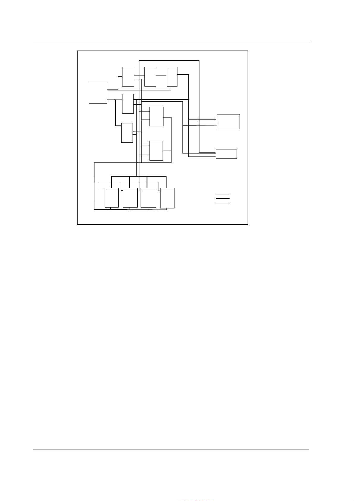
Figure 3 CPU board block diagram, B-CPU2/3
Sw
cartridge
connector
CPU BUS
Control logic
IO-decoding and wait state generation takes place in GAL IC and and in the processor. Code
memory (EPROM) and working RAM (DRAM) are designed to be linear, and static RAM and EPROM
are mapped in I/O space.
Wait state generators
The processor and the GAL IC have internal wait state generators for their predecoded chip select
pins. The wait state generator in the GAL IC is used also by the other boards connected to the CPU
bus.
Halt detection
NMI-interrupt is generated by the power control logic. The interrupt signal in the CPU means that all
supply voltages except +5V for the CPU board will be switched off shortly. NMI interrupt service
program then saves all necessary parameters in the static RAM before supply voltages fail.
When hardware detects HALT command all signals generated in the CPU board as well as all the
outputs to the CPU mother board are left floating in high impedance state; only DRAM refreshment
cycle continues to occur. The halt state will continue until a RESET pulse from the power control
logic circuit is received.
6
Document No. 8002818-1
Page 11

External bus
External bus signals are AC logic level signals. Series resistors are used to limit signal ringing when
the signals change their states. Additional signal filtering is performed in the CPU mother board.
Main peripherals
QUART
Four series channel Quart is used.
SAA1099
IC SAA1099 is used as alarm sound generator.
M48T18
Lithium battery back-up 8 kB static RAM with a real-time clock.
CPU boards and softwares
CAUTION The IC contains a lithium battery. Discard the battery according to
local regulations.
Watchdog functions
The UPI board and the primary display controller board interrupts the CPU board continuously in
order to state that everything runs smoothly. The CPU board refreshes the watchdog timer in the
power supply unit in order to prevent reset pulse. If the UPI board, primary display controller board
or CPU board stops the refreshment, the monitor will be reset in order to prevent false information
to be displayed on the screen.
2.3 Software Card, L-ANE01S, L-ANE01AS, L-ICU01S, L-ICU01AS
The software card is a flash memory card, 4MB (PCMCIA)
L-ICU01/L-ICU01A software is developed for critical care monitoring and L-ANE01/L-ANE01A is
for anesthesia monitoring. Anesthesia record keeping capability is included in the anesthesia
monitor software L-ANE01/L-ANE01A as standard. The software L-ANE01A and L-ICU01A include
extended arrhythmia analysis.
L-ANE01/L-ANE01A/L-ICU01/L-ICU01A is license software. The license agreement that is
delivered with software should be archived in a secure location. Relevant license number may have
to be referred when contacting Datex-Ohmeda service/support. The licence number is needed also
for future software upgrades.
The L-xxx01(A) software is not delivered separately without the B-CPU4 board, the software is
loaded on the B-CPU4 board already at the factory.
The L-xxx01(A)S software is used for service purpose only and is stored on a separate Software
Card (PCMCIA, 4 MB). See section 3.3.1 “Loading/replacing software on CPU Board, B-CPU4.””
CAUTION The software card is not write protected. For safety reasons do not use software
cards in any other purposes, or on any other platforms than they are designed for.
Document No.8002818-1
7
Page 12

S/5 Anesthesia Monitor and S/5 Critical Care Monitor
2.4 Software Card, S-00A01S, S-00A02S, S-00C01S, S-00C02S, L-00A03
The software card is a flash memory card, 4MB (PCMCIA).
The monitor software is named S-00A01/S-00A02/L-00A03/L-00A04/S-00C01/S-00C02. The
software L-00A03/L-00A04 is needed when the monitor is used for anesthesia record keeping. S00C01/S-00C02 software is developed for critical care monitoring functions and S-00A01/S00A02 is for anesthesia monitoring functions. The softwares S-00A02/S-00C02/L-00A04 include
extended arrhythmia analysis.
Anesthesia Record Keeping software, L-00A03/L-00A04 is license software. The license
agreement that is delivered with software should be archived in a secure location. Relevant license
number may have to be referred when contacting Datex-Ohmeda service/support. The licence
number is needed also for future software upgrades.
The S(L)-00xxx software is not delivered separately without the B-CPU4 board, the software is
loaded on the B-CPU4 board already at the factory.
S(L)-00xxxS software is used for service purposes only and is stored on a separate Software Card
(PCMCIA, 4 MB). See section 3.3.4 “Loading/replacing software on CPU Board, B-CPU4.”
CAUTION The software card is not write protected. For safety reasons do not use software
cards in any other purposes, or on any other platforms than they are designed for.
2.5 Software Card, S-ANE98S, S-ARK98S, S-ICU98S
The Software Card is a flash memory card, 4 MB (PCMCIA).
The features of the 98 softwares are the same as in corresponding 97 softwares. The only
difference between the 98 softwares and the 97 softwares is the compatibility with the B-CPU4
boards. The 97 softwares are incompatible with the B-CPU4 boards.
The S-xxx98 softwares are not delivered separately without the B-CPU4 board, the softwares
are loaded on the B-CPU4 boards already at the factory.
S-xxx98S softwares are used for service purposes only, and are stored on separate Software Cards
(PCMCIA). See section 3.3.4 “Loading/replacing software on CPU Board, B-CPU4.”
CAUTION The software card is not write protected. For safety reasons do not use software
cards in any other purposes, or on any other platforms than they are designed for.
2.6 Software Cartridge, S-ANE97, S-ARK97, S-ICU97
CAUTION The software cartridge cannot be disassembled. There are no serviceable parts
inside.
The Software Cartridge contains the main software, which includes software for the CPU board,
display controller boards, UPI board and network board.
8
Document No. 8002818-1
The monitor software is named S-ANE97/S-ARK97/S-ICU97. The software S-ARK97 is needed
when the monitor is used for anesthesia record keeping. S-ICU97 software is developed for critical
care monitoring and S-ANE97 is for anesthesia monitoring.
Page 13
2.7 Connectors and signals
2.7.1 Internal connectors
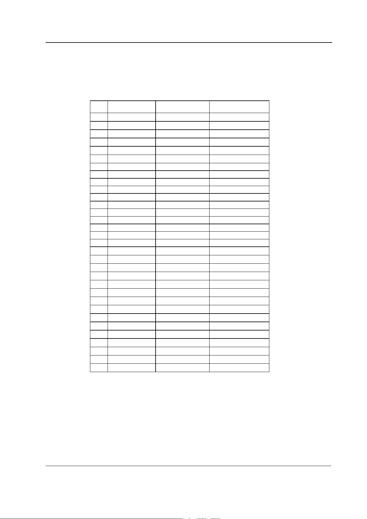
CPU bus - CPU mother board
ab c
1 +15 V AGND DGND
2 -15 V BALE DGND
3 SA0 SA1 DGND
4 SA2 SA3 RESET_RS485
5 SA4 SA5 -RESET_RS485
6 SA6 SA7 DATA_RS485
7 SA8 SA9 -DATA_RS485
8 SA10 SA11 TXDD_RS232
9 SA12 SA13 RXDD_RS232
10 SA14 SA15 PWM_ECG
11 SA16 SA17 BIT1IN
12 SA18 SA19 TXDC
13 SA20 SA21 RXDC
14 SA22 SA23 RTSC
15 -SMEMR -SMEMW CTSC
16 -SIOR -SIOW TXDB
17 CLK -RESET RXDB
18 -IOCHRDY IRQ10 RTSB
19 N/C_1 IRQ11 CTSB
20 N/C_2 IRQ12 TXDA
21 -SBHE IRQ15 RXDA
22 SD0 SD1 RTSA
23 SD2 SD3 CTSA
24 SD4 SD5 AUDIO_OUT
25 SD6 SD7 +5 V
26 SD8 SD9 +5 V
27 SD10 SD11 +5 V
28 SD12 SD13 +5 V
29 SD14 SD15 ON/STBY
30 +15 VD -RESET_CPU +5 V_CPU
31 +15 VD +32 VD REFRESH_WD
32 GNDD GNDD POWER_FAIL
CPU boards and softwares
Document No.8002818-1
9
Page 14

S/5 Anesthesia Monitor and S/5 Critical Care Monitor
10
Document No. 8002818-1
Page 15
CPU boards and softwares
3 SERVICE PROCEDURES
3.1 General service information
Field service of the CPU boards and software is limited to replacing the faulty printed circuit boards
or mechanical parts. The printed circuit boards should be returned to Datex-Ohmeda for repair.
Datex-Ohmeda is always available for service advice. Please provide the unit serial number, full
type designation, and a detailed description of the fault.
CAUTION Only trained personnel with appropriate equipment should perform the tests and
repairs outlined in this section. Unauthorized service may void warranty of the unit.
3.2 Service check
These instructions include complete procedures for a service check. The service check is
recommended to be performed after any service repair. However, the service check procedures can
also be used for determining possible failures.
The procedures should be performed in ascending order.
The instructions include a check form (Appendix A) which should be filled in when performing the
procedures.
The mark
the procedure.
The procedures are designed for monitors with S/5 monitor software of revision 01. However, most
of the procedures also apply to monitors, which contain some other monitor software
type/revision.
? in the instructions means that the check form should be signed after performing
3.2.1 Recommended tools
Tool Order No. Notes
Command Bar / CommandBoard
M-REC
M-NE(12)STPR/M-ESTPR/M-ESTP
Datex-Ohmeda gas monitor e.g. Capnomac Ultima
UPI Interface cable 887245
Screwdriver
General
Make sure that no cables and modules are connected to the Central Unit. Lift off the Video display
with its stand, if placed on the Central Unit.
11
Document No.8002818-1
Page 16

S/5 Anesthesia Monitor and S/5 Critical Care Monitor
CPU board
1. Check that the CPU board back plate is clean and intact. Check that both CPU and software
device plates are intact.
?
2. Check that the grounding plate under the CPU board rear panel is attached properly and are
not bent.
NOTE: Older PC boards may not include the grounding plates.
?
3. The SRAM/Timekeeper battery on the CPU board is recommend to be replaced after every 8
years. Replace the battery, if necessary.
NOTE: The Factory Reset should be performed if the SRAM/Timekeeper battery, or the
SRAM/Timekeeper chip is replaced.
General
?
4. Check that all the rear side PC boards are secured to the Central Unit with two screws.
?
5. Install the video display together with the Command Board, the M-NESTPR/M-ESTPR/M-
ESTP and the M-REC. Connect the mains power cord and turn the monitor on.
Check that the fan is running.
?
6. Check that the monitor starts up properly, i.e. the alarm LEDs on the Command Board turn
blank, the start-up sound is heard from the loudspeaker and the normal monitoring screen
appears. No error messages should appear onto the screen.
?
7. Check that the connected modules are recognized, i.e. the needed parameter information is
shown on the screen and the M-REC records two lines of start-up information.
If some parameter information is missing, check the screen configuration from the
MONITOR SETUP -menu.
12
Document No. 8002818-1
?
8. Check that the clock on the screen shows correct time. Adjust the time, if necessary.
Monitor Setup - Time And Date
NOTE: If the clock shows time 0:00 continuously (at successive start-ups), the
SRAM/TIMEKEEPER chip on the CPU board, or its battery, is need to be replaced.
Page 17

CPU boards and softwares
The FACTORY RESET should be performed after the made replacement.
?
9. Check the loudspeaker volume settings by setting the alarm sound:
Alarms Setup - Alarm Volume
Test the whole volume scale from 1 to 10 by turning the ComWheel and check that the
alarm volume changes correspondingly. The alarm sound should be clear and audible with
all the settings.
?
10. Enter the service menu.
Monitor Setup - Install/Service (password 16-4-34) - Service (password 26-23-8)
Take down the information regarding monitor software.
?
11. Select SERVICE LOG from the menu. Record the Service log onto the M-REC by selecting
RECORD LOG. Check the content of recording for possible problems, then empty the Service
log by selecting RESET LOG from the menu.
?
12. Test the Central Unit watchdog circuitry:
Monitor Setup - Install/Service (password 16-4-34) - Service (password 26-23-8) Set/Test -
Select the watchdog tests one by one and check that the monitor performs a restart in all
other cases except when selecting the WD by UPI .
NOTE: When selecting WD BY OVERLOAD, restarting should take place approximately after
15 seconds. With the other tests restarting takes place within a couple of seconds.
If restarting did not take place, try to locate the fault:
Watchdog --> CPU board /Power supply unit
WD by Overload --> CPU board
WD by GSP --> Primary display controller board / CPU board
?
13. Check that the monitor is capable of storing the trend information and temporary settings in
a short (max. 15 minutes) standby.
Turn the monitor to standby and disconnect the power cord. Wait for two minutes, then
reconnect the power cord and turn the monitor back on. The monitor should perform a
“Warm start” which means the trend information and temporary settings should still be
available.
If the monitor performed a “Cold start” instead, the battery fuse or the lead acid battery of FCU8 is needed to be replaced.
13
Document No.8002818-1
Page 18

S/5 Anesthesia Monitor and S/5 Critical Care Monitor
NOTE: The B-CPU2/3/4 require 2 Amps battery fuse (P/N 51063).
The information regarding a start-up is saved also in the Service log.
?
14. Turn the monitor off. Connect a Datex-Ohmeda gas monitor to the UPI board using the UPI
Interface cable P/N 887245. Turn the monitors on and set the interface according to the
interfaced gas monitor:
Monitor Setup - Install/Service (password 16-4-34) - Installation - Interfacing -
Gases/Spiro SpO2 -
Make sure that also the screen configuration is appropriate
Monitor Setup - Screen 1 Setup - Waveform Fields - Field 5 - Pleth
Check that the interfaced parameters (numerics) appear onto the monitor screen.
- FIELD 6 - CO
2
?
15. Perform an electrical safety check and a leakage current test.
?
16. Check that the Central Unit functions normally after the performed electrical safety check.
?
• Fill in all necessary documents.
3.3 Disassembly and reassembly
NOTE: Switch the monitor to standby and press the service reset switch at least for five seconds
before detaching any PC boards (or software cartridge).
1. Remove screws and detach all PC boards and cover plates from the right side of the CPU
board.
2. Remove the screws on the CPU board and detach the software cartridge, if installed.
3. Detach the CPU board.
Reassembly should be made in reversed order.
14
Document No. 8002818-1
NOTE: When reinstalling PC boards, push the boards carefully until they stop before fastening them
with screws.
Page 19

3.3.1 Loading/replacing software on CPU Board, B-CPU4
See also “Replacing CPU Board, B-CPU4” on Part I/System Installation.
NOTE: All user settings will be lost after loading/replacing the software.
NOTE: You can load the software to only one CPU4 board from the Software Card. During the
loading of the software the serial number of the CPU4 board is written on the Software Card, and if
the loading for some reason should fail, the software can be loaded again to the same CPU4
board, but not to any other CPU4 board.
1. Make sure that the power is turned off from the F-CU8 . Press and hold the service reset
button on the rear panel for at least five seconds or until an audible tone is generated.
2. Put off the lid for backplate on B-CPU4 board.
CPU boards and softwares
!
3. Insert the new software card into the card drive slot and firmly press the card in position.
4. Turn the power on.
5. Wait for approximately 80 seconds. After the start up screen appears enter the Service View
and make sure that the information regarding monitor software has been updated.
Memorize the serial number of new software.
6. Remove the software card and attach the lid for back plate.
7. Pick up the software device plate with the serial number of new software and attach the
device plate on the B-CPU4 back plate.
NOTE: The license agreement of L-xxx01(A) software needs to be in accordance with the
corresponding L-xxx01(A) serial number, respectively. Make sure you archive the license
agreement in a secure location.
8. Perform Factory Reset.
9. Set the time and date.
10. Check that there are no error messages on the screen.
11. Restore the original user settings, if necessary.
15
Document No.8002818-1
Page 20

S/5 Anesthesia Monitor and S/5 Critical Care Monitor
See the troubleshooting flowchart for software card, if the downloading of new software failed.
NOTE: Right after the monitor software downloading the start-up time is considerably longer.
3.3.2 Performing Factory Reset
NOTE: The Factory Reset is necessary after loading software, replacing CPU board or
SRAM/Timekeeper battery.
NOTE: The Factory Reset will restore all your customized defaults, including language selection, to
factory defaults.
1. Press the
2. Select Install/Service and password (16-4-34).
3. Select Service and password (26-23-8).
4. Select Set/Test and perform Factory Reset.
5. The monitor will perform an automatic restart. After the restart is completed, restart the
monitor also manually by the On/Standby –switch.
Monitor Setup key.
3.4 Adjustments and calibrations
It is not necessary to do calibrations or adjustments to the CPU board or software.
16
Document No. 8002818-1
Page 21

4 TROUBLESHOOTING
4.1 Troubleshooting flowcharts
4.1.1 Monitor
M onitor not functioning
CPU boards and softwares
O n/S T B Y sw itch 'O N '
D isplay connected?
Keyboard connected?
Pow er cord
connected?
No
C onnect pow er cord
R em ove all m odules
a n d tu r n p o w e r o n
Is fan running?
Yes
Any LEDs lit
on keyboard?
Yes
Start-up texts
appear on
screen?
Yes
Yes
No
No
OK?
No
No
No
C onnect and check
No
OK?
D isconnect and reconnect the pow er cord
Yes
OK?
No
Turn pow er on by shorting
13 (GND) and 20 (ON/STBY)
at G as Interface board connector
Is fan running?
Yes
Keyboard trouble. S ee part II
for troubleshooting.
Yes
The pow er supply unit
w as shut dow n by instant over
voltage in the m ains.*)
*) N O T E ! In c a s e o f s h o rt p o w e r o ff
and autom atic start-up see section
"P ow er logic board/P rotections" to find
possible reason.
No
C lock etc
appears on
th e scre en ?
Yes
Plug in a m odule
M odule data
appear on
th e scre en ?
No
Yes
Pick up next
m odule
Faulty C entral U nit. G o to
No
next page.
A nother
m odule w orks
in sam e place?
No
C h e c k o th e r
positions w ith sam e
m o d u le , W o rk ?
Figure 4 Monitor troubleshooting flowchart
Yes
Faulty m odule. G o to M odule
troubleshooting.
Yes
Faulty m odule m other board
F a u lty C e n tra l U n it, g o to
No
next page.
17
Document No.8002818-1
Page 22

S/5 Anesthesia Monitor and S/5 Critical Care Monitor
4.1.2 Digital section
Digital section faulty.
Remove all modules and boards
except CPU, UPI and display
controller board
Turn
the monitor on.
OK ?
Yes
Insert one of the removed
boards.
Turn
the monitor on.
OK ?
No
Replace faulty board
No
Yes
A
beep is
heard when
monitor is
turned
on ?
Yes
Is tone
same as at
OK start ?
No
Is tone
same as at
OK start but
longer ?
No
No
Replace CPU board.
Yes
Try with another display
OK?
No
Yes
Replace Display controller.
Yes
Replace display
18
Document No. 8002818-1
Is tone
lower and longer
than at OK
start ?
Yes
Figure 5 Digital section troubleshooting flowchart
Replace UPI-board
Page 23

4.1.3 Software Card
A
CPU boards and softwares
SERVICE PROCEDURE:
Downloading of Service software or
Upgrade software from a software
card onto the CPU board.
Insert the software card into
the card slot.
Turn the power ON.
Wait for 80
seconds.
Start-up display
appears?
Yes
Has the information
regarding monitor software
been updated on the
Service View?
Yes
Remove the
software card.
Perform Factory
Reset.
OK.
ttach the device plate with the serial
number of new software.
No
No
Check the software
card's connection
in the card slot
and try again.
Yes
OK ?
No
Try with another
software card.
Please read the
note below.
No
Replace the CPU
board and try again.
NOTE:
The software card may be
defective, or all available
software has already been
downloaded from the
software card.
OK
OK
Figure 6 Software Card troubleshooting flowchart
19
Document No.8002818-1
Page 24

S/5 Anesthesia Monitor and S/5 Critical Care Monitor
4.2 Error messages
SRAM Error
The SRAM memory is located on the CPU board. The SRAM Error is due to memory malfunction.
Restart the monitor. If the problem persists, replace the SRAM timekeeper (B-CPU1, B-CPU2 rev.
00) or the battery for SRAM timekeeper (B-CPU2 rev 01, B-CPU3/4). Remember to perform factory
reset after the replacement.
EPROM Error
The EPROM Error message is displayed due to problems in the communication between the CPU
board and the software memory. Check that the software cartridge is properly connected to the BCPU2/3 board. If the problem persists, first replace the software cartridge, then the CPU board. In
case of the B-CPU4 board, replace the CPU board. Remember to perform factory reset after the
replacement.
EEPROM Error
RAM Error
The EEPROM memory is located on the CPU board. The EEPROM Error message is displayed due to
memory malfunction. Perform factory reset. If the problem persists, replace the CPU board.
Remember to perform factory reset after the replacement.
The RAM memory is located on the CPU board. The RAM Error message is displayed due to memory
malfunction. Replace the CPU board. Remember to perform factory reset after the replacement.
20
Document No. 8002818-1
Page 25

5 SERVICE MENU
The monitor has Service menu, which is a useful tool to examine monitor functions and to
troubleshoot in case a fault occurs.
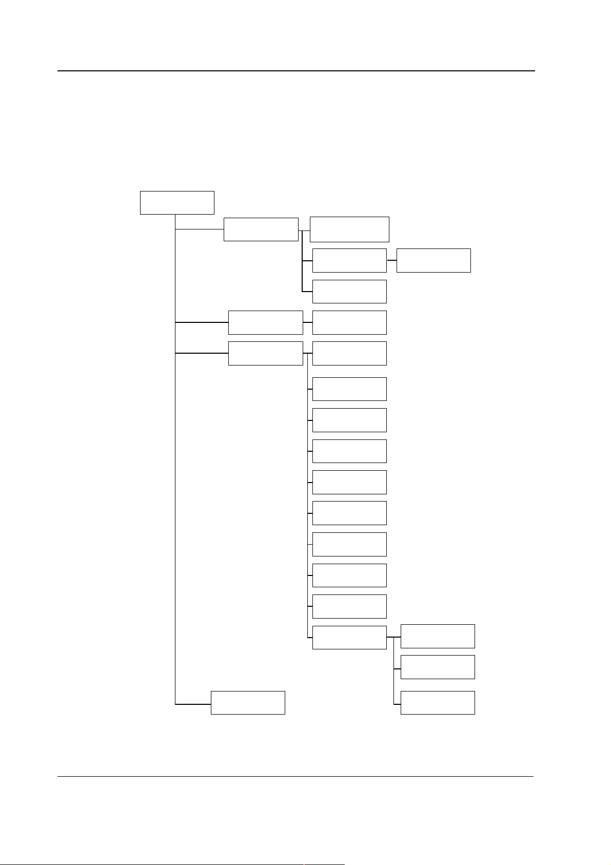
5.1 Service menu structure
Service M enu
Frame
CPU boards and softwares
Memory
Communication Analog Outputs
Network
MemCards
Display
Keyboard Keyboard Type
Parameters Gas Unit
Set/Test
Power Supply Battery
Keyboard Log
ECG
STP
P / PT
PP
COP
NIBP
NMT
M-SAT
More . . .
Country Settings
Network Comm
Network Status
MemCard Comm
MemCard Status
General
Gases
Spirometry
Interface
TONO
EEG
DIS Interfacing
Service Log
Record Data
Remote Access
Error History
Event History
Alarm History
Maintenance Planned Maint.
Repair
Upgrade
21
Document No.8002818-1
Page 26
S/5 Anesthesia Monitor and S/5 Critical Care Monitor
r
y
g
5.1.1 Service menu structure in S-xxx98(S) software and earlier
The Service Menu structure in S-xxx98(S) software and earlier is basically similar to the
service menu structure in S/5 monitor software. See the picture below. The Install/Service
and Service passwords are exactly the same.
Service View
Monito
Keyboard Keyboard Type
Modules Gas Unit
Voltages
Watchdog Tests
ESTP:ECG
ESTP:STP
P/PT
PP
COP
Remote AccessCommunication
22
Document No. 8002818-1
NIBP
NMT
N-SAT
More modules
Interface
Batter
Memory Module Service Lo
Page 27
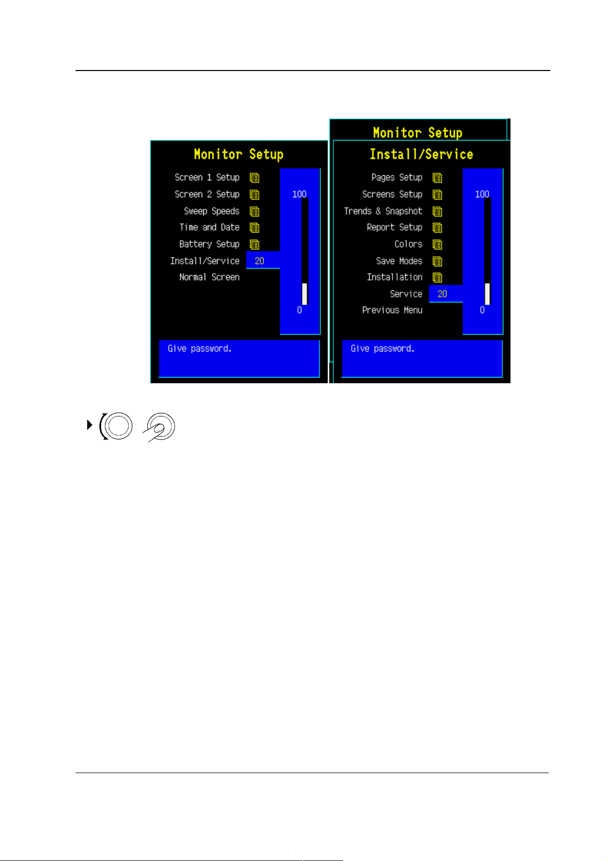
5.2 Service
CPU boards and softwares
1. Press the Monitor Setup key.
2. Select Install/Service (password 16-4-34).
3. Select Service (password 26-23-8).
23
Document No.8002818-1
Page 28

S/5 Anesthesia Monitor and S/5 Critical Care Monitor
5.3 Service menu
The field on the right shows software versions and their release dates of different parts of the
monitor, control numbers of measuring boards and serial numbers of modules (if available).
See descriptions for Service Menu submenus from
sections:
5.4 Frame
5.5 Display
5.6 Keyboard
5.7 Parameters
5.8 Set/Test
5.9 Service Log
5.10 Record Data
5.11 Remote Access
Scroll Vers enables to scroll the field on the right side.
‘-More-’ indicates that there are more lines to be viewed.
Record Vers
By choosing this selection, the software versions and
other information are printed to the device defined in the
Record Data menu.
5.4 Frame
The frame menu includes service menus common for the
frame.
24
Document No. 8002818-1
Page 29
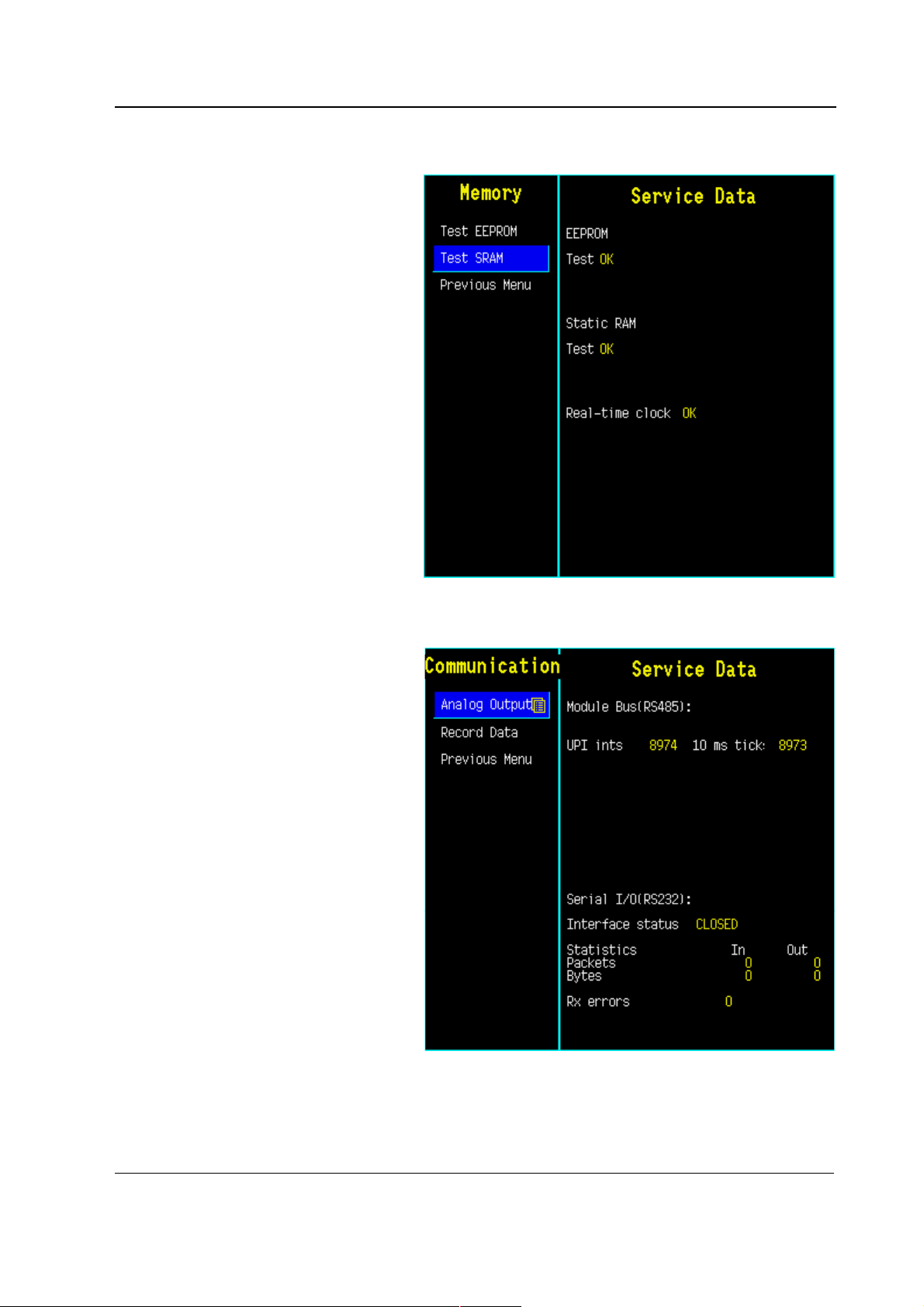
5.4.1 Memory
A service menu to check the status of the memory used in
CPU board of the monitor.
Test Memory tests the condition of the EEPROM/Flash
memory component of the CPU board. If the result of the
test is Fail, see section “Error messages.”
Test SRAM tests the Static RAM memory of the CPU
board in a similar way as the EEPROM/Flash memory. If
the result of the test is Fail, see section “Error
messages.”
Real time clock test is run at every start up and also
during the operation of the monitor. If the result of the
test is fail, the battery for SRAM timekeeper should be
exchanged.
CPU boards and softwares
5.4.2 Communication
A service menu for showing information about internal
RS-485 and external RS-232 communication.
Module Bus (RS485) view shows information related to
the module bus.
UPI ints shows the number how many times the CPU
board has sent an interrupt to UPI board. The running
number should raise at a frequence of at least 100 Hz. If
the numbers don't raise there is trouble with the interrupt
line between CPU board and UPI board or with the boards
themselves.
The 10 ms tick shows how many 10 ms intervals the UPI
microprocessor has been on after last UPI reset. The UPI
microprocessor counts the 10 ms intervals. The number
must be running all the time at the frequency of 100 Hz. If
the number doesn't rise, the problem is in the UPI board.
Serial I/O (RS-232) view shows information about the
communication through the UPI board RS232 serial
connector X3.
Interface status shows whether the interface through the
connector is OPENED, ACTIVE or CLOSED. Opened
indicates that the hardware and software for the interface
is running but there is no connection or that there have
been errors in using the interface. Active indicates that
the interface is operating normally. Closed indicates that
the necessary hardware is not present.
Statistics In/Out show the numbers of received and
transmitted data packets and data bytes.
Rx errors show the number of received erroneous data
packets.
25
Document No.8002818-1
Page 30
S/5 Anesthesia Monitor and S/5 Critical Care Monitor
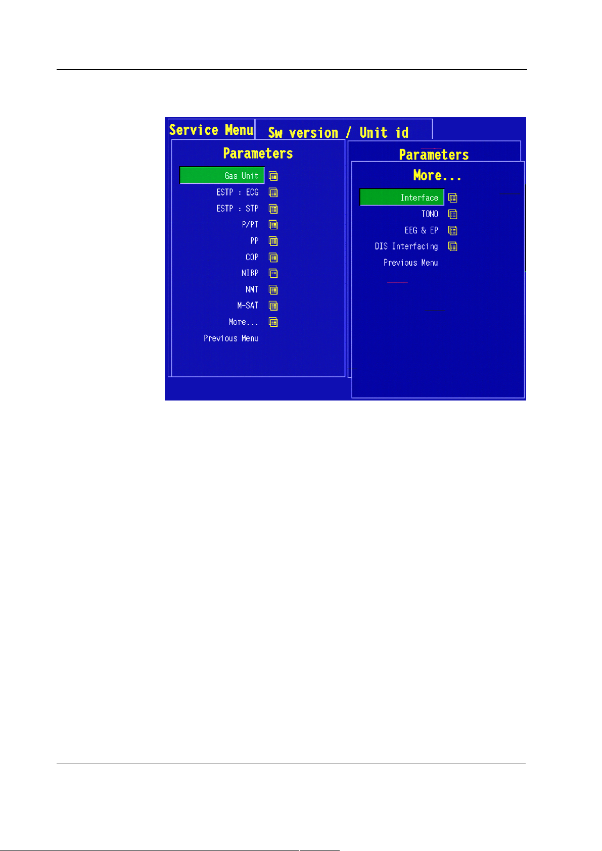
5.5 Parameters
The parameter menus are
explained in each parameter
chapter.
26
Document No. 8002818-1
Page 31
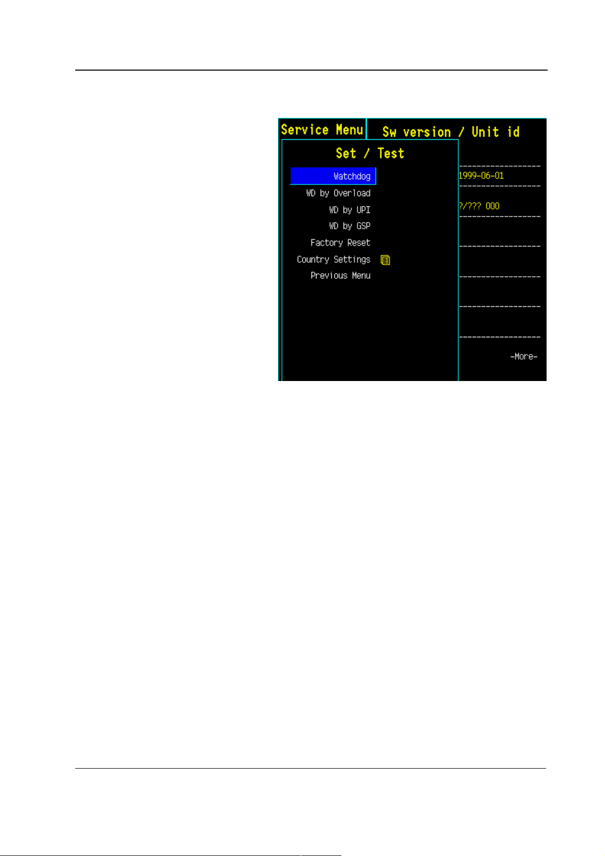
5.6 Set/Test
In the power supply unit, there is a safety element, which
needs refreshing at least every 1.5 seconds. If the main
CPU’s software will not refresh, safety element gives reset
to main CPU. In normal operation the main CPU’s
software refreshes safety element every 0.2 seconds.
The purpose of the safety element is to restart the monitor
if there is a serious malfunction. This feature is useful in
two cases: when the main CPU’s software is not able to
control the monitor, and when the software controls the
monitor but detects a serious malfunction. Watchdog
tests ensure the proper functionality of the safety
element’s various sections.
Watchdog test ensures directly that the watchdog of the
power unit functions properly. Choosing this test prevents
safety element from refreshing and shows running
seconds with an accuracy of 0.1 seconds.
The test should have the following result when the safety
element is working properly: The monitor will restart after
1.5 seconds from the start of the test. In malfunction:
‘>20 s’ is displayed, and the test will interrupt. In this
case, the fault is in the safety element of the power unit.
WD by Overload test ensures the functionality of a
feature, where the software controls the monitor, but
detects an overload situation in the main CPU.
The test should have the following result when the feature
is working properly: The monitor will restart after 15
seconds from the start of the test.
WD by UPI test ensures the functionality of a feature,
where the software controls the monitor, but detects a
malfunction in the UPI processor and restarts the
UPI4(NET) board. The test will prevent the UPI processor
from functioning during the test.
Immediately after the test starts the plotting stops. The
test should have the following result when the feature is
working properly: The monitor will restart the UPI4(NET)
board without any visual effects.
WD by GSP ensures the functionality of a feature, where
the software controls the monitor, but detects a
malfunction in GSP processor (located on the primary
display controller board) and performs a restart. The test
will prevent GSP processor from functioning during the
test.
Immediately after the test starts, the screen update
stops. The test should have the following result when the
feature is working properly: The monitor will restart after 5
seconds from the start of the test.
Factory Reset restore factory default settings and clear
data memories. Factory reset should be run if monitor
software is replaced or if the SRAM/Timekeeper IC, or its
battery is replaced.
CPU boards and softwares
27
Document No.8002818-1
Page 32

S/5 Anesthesia Monitor and S/5 Critical Care Monitor
5.6.1 Country Settings
National Reqs
Select software features, which include national
requirements.
Power Frequency
Set power frequency (50 Hz/60 Hz). This setting is used
to filter out possible power frequency interference from
the parameter measurements.
Time format
Set time format of the real time clock (24 h/12 h).
28
Document No. 8002818-1
Page 33

5.7 Service Log
Error, event, alarm and maintenance data is stored in
Service Log.
The service log contains information about the occurred
monitor errors, events and alarms since the last factory
reset or service log reset. The service log is saved in the
EEPROM memory of the main CPU board. The user can
also store different maintenance events to the
maintenance log.
Maintenance menu is for setting and viewing the
maintenance information of the monitor
Error History is for selecting the error history view onto
the right side of the menu.
Event History is for selecting the event history view onto
the right side of the menu.
Alarm History is for selecting the alarm history view onto
the right side of the menu.
Scroll Last Er (Ev) is for scrolling the error / event /
alarm information on the right side of the menu.
Scroll Counters is for scrolling the error / event / alarm
counters on the right side of the menu.
Record Data is for recording the service log information
onto the M-REC paper, the laser printer or the memory
module depending on the selection in the Record Data
service menu.
Reset Log is for clearing up the content of the service
log. This function is recommended to be run after a
performed maintenance. In Error/Event history view the
Reset Log command clears up both error and event log. In
Alarm History view the Reset Log command resets only
the alarm history log.
CPU boards and softwares
5.7.1 Error History
Last errors: The section shows the last monitor errors
and the time of their occurrence.
Error counters: The section contains counters for each
different (detected) monitor errors. The time of
occurrence of the last error is shown beside each counter.
Last log reset: The date and the time of last Error/Event
log reset.
Possible errors:
Fast cold start indicates a number of erroneous cold
starts with power off time less than 20 seconds. The
reason can be either a failing lead acid battery or a
software problem that was solved by the hardware
watchdog circuitry located in the monitor’s power supply
unit.
GSP watch-dog time-out indicates an erroneous restart
controlled by the main CPU board and caused by the
display controller board. The restart is listed as a fast cold
start.
UPI watch-dog time-out indicates an erroneous restart
controlled by the main CPU board and caused by the UPI
or UPINET board. The restart is listed as a fast cold start.
29
Document No.8002818-1
Page 34

S/5 Anesthesia Monitor and S/5 Critical Care Monitor
5.7.2 Event History
Last events: The section shows the last events and the
time of their occurrence.
Event counters: The section contains counters for each
different (detected) events. The time of occurrence of the
last event is shown beside each counter.
Last log reset: The date and the time of last Error/Event
log reset.
Possible events:
Cold start is a start-up with power off time more than 15
minutes. The trend memory is cleared and monitoring
starts with the user default settings.
Warm start is a start-up with power off time less than 15
minutes. The trend information and possible temporary
settings are still available.
5.7.3 Alarm History
Last alarms: The section shows the last events and the
time of their occurrence.
Alarm counters: The section contains counters for each
different (detected) events. The time of occurrence of the
last event is shown beside each counter.
Last log reset: The date and the time of last alarm log
reset.
30
Document No. 8002818-1
Page 35

5.7.4 Maintenance
The maintenance history log gives the user a possibility to
store the maintenance history of the monitor. The user
can store different planned maintenance (PM) events,
repairs and upgrades to the maintenance history log.
Running hours: shows how many hours the monitor has
been on. This value cannot be reset by user.
since This date and time is set at the factory and it shows
the manufacturing date and time. This date and time
cannot be reset by user.
since last 1 year PM: shows the running hours since the
last 1 year PM storing.
Last events: The section shows the last maintenance
events and the time of their occurrence.
Event counters: The section contains counters for each
different maintenance events. The time of occurrence of
the last event is shown beside each counter.
CPU boards and softwares
Planned Maintenance
1 Year PM gives you possibility to store a 1 year PM event
to the maintenance history log.
Other PM gives you possibility to store another PM event
to the maintenance history log.
Notify on PM if yes is selected, the “Planned
maintenance recommended” notification is shown on the
message field on the display at the startup of the monitor
after one year has passed since the last 1 year PM. To
remove this message you can store a new 1 year PM to
the maintenance history log. If no is selected, the monitor
won’t display the “Planned maintenance recommended”
notification. Configure this setting according the
agreement with the customer.
31
Document No.8002818-1
Page 36

S/5 Anesthesia Monitor and S/5 Critical Care Monitor
Repair
The repair menu gives the user a possibility to store repair
events to the maintenance history log. The different
repairs that can be saved are: Display, Power Supply,
Recorder, Frame (e.g. board in the frame), Parameters
(e.g. a board in the parameter module) or Other (a
miscellaneous repair not specified by previous options).
Upgrade
The upgrade menu gives the user a possibility to store the
upgrades to the maintenance history log.
32
Document No. 8002818-1
Page 37

5.8 Record Data
In this menu the user can specify where to print from any
menu. The setting goes into the permanent memory of
the monitor. Only one option can be chosen at a time.
The options where to print are: To Printer, To Recorder
and To Memory Card. When any of the front panel keys of
the recorder module, M-REC is pressed the output is the
recorder module despite of the setting of Record Data
menu.
CPU boards and softwares
5.9 Remote Access
Remote Access menu is for setting the interface with an
external PC that runs the Virtual Support
which is a service diagnostic tool for remote diagnostics
purposes.
When the access mode is set to Normal (the default), the
PC can only read service menu data from the monitor.
With the access mode Extended the PC can also activate
the monitor’s service menu functions.
NOTE: Patient monitoring is not possible when
the access mode Extended is selected. The
access mode turns back Normal if the monitor
is restarted or if the service menu is closed.
TM
software,
33
Document No.8002818-1
Page 38

S/5 Anesthesia Monitor and S/5 Critical Care Monitor
6 SPARE PARTS
6.1 Spare parts list
NOTE: Only changed part numbers are listed under later revisions. To find the desired part: check
first the list of the revision that corresponds your device. If the part is not listed there, check the
previous revision, etc. until you find the right number.
6.2 Products
* this part is recommended for stock
6.2.1 CPU boards and softwares
- CPU Board *B-CPU1
Item Description Order no.
Software Cartridge (all except USA) S-STD93
Software Cartridge (USA) S-STD
Item Description Order no.
- CPU Board *B-CPU2
- CPU Board *B-CPU3
- Software Cartridge S-STD94
- Software Cartridge S-ARK94
- Software Cartridge S-STD95
- Software Cartridge S-ARK95
- Software Cartridge S-STD96
- Software Cartridge S-ARK96
Item Description Order no.
- Software Cartridge S-ANE97
- Software Cartridge S-ICU97
- Software Cartridge S-ARK97
Item Description Order no.
- CPU Board *B-CPU4
- Software Card *S-ANE98S
- Software Card *S-ICU98S
- Software Card *S-ARK98S
Software Card S-00A01S
Software Card S-00A02S
Software Card S-00C01S
Software Card S-00C02S
Software Card L-00A03S
Software Card L-00A04S
34
Document No. 8002818-1
Page 39
Software Card L-ANE01S
Software Card L-ANE01AS
Software Card L-ICU01S
Software Card L-ICU01AS
6.2.2 CPU Board, B-CPU1
Item Description Order no.
- SRAM 2kx8, Timekeeper *139423
- Grounding plate 885400
6.2.3 CPU Board, B-CPU2 rev. 00
Item Description Order no.
- SRAM 8kx8, Timekeeper *139422
- Grounding plate 885400
CPU boards and softwares
6.2.4 CPU Board, B-CPU2 rev. 01
Item Description Order no.
- Battery for SRAM/Timekeeper *197230
- Grounding plate 885400
6.2.5 CPU Board, B-CPU3
Item Description Order no.
- Battery for SRAM/Timekeeper *197230
- Grounding plate 885400
6.2.6 CPU Board, B-CPU4
Item Description Order no.
- Battery for SRAM/Timekeeper *197230
- Lid for back plate 894934
- Screw 617110
35
Document No.8002818-1
Page 40

S/5 Anesthesia Monitor and S/5 Critical Care Monitor
7 EARLIER REVISIONS
This service manual fully supports earlier revisions except,
Item Manual and document number
8-Module Frame, F-CU8 (rev 01/rev.02) Service Manual, 880 850
CPU Board, B-CPU1 (rev 01) Service Manual, 882 580
Software Cartridge, S-STD/S-STD93 Service Manual, 882 580
Software Cartridge, S-STD94/S-ARK94 Service Manual, 885 930
Software Cartridge, S-STD95/S-ARK95 Service Manual, 885 930
Software Cartridge, S-STD96/S-ARK96 Service Manual, 885 931
Service Menu descriptions related to softwares of level 97/98 Technical Reference Manual 895 704
36
Document No. 8002818-1
Page 41

Appendix A, CPU boards and softwares
APPENDIX A
37
Document No. 8002818-1
Page 42

S/5 Anesthesia Monitor and S/5 Critical Care Monitor
38
Document No. 8002818-1
Page 43
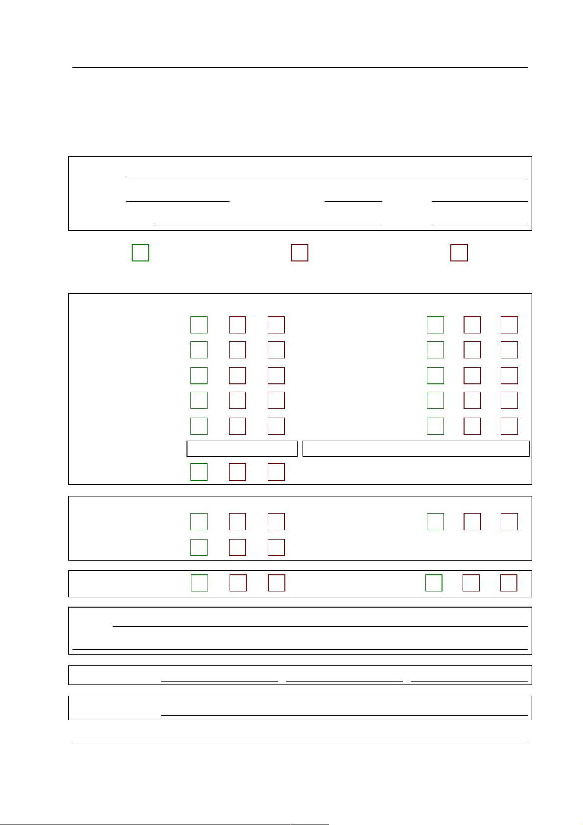
SERVICE CHECK FORM
CPU boards
Customer
Appendix A,Service c heck form, CPU boards and softwares
Service
Service engineer Date
OK = Test OK N.A. = Test not applicable Fail = Test Failed
OK N.A. Fail OK N.A. Fail
1. Device plates 2. Grounding plate
3. SRAM/Timekeeper
battery
5. Fan 6. Starting
7. Module
communication
9. Loudspeaker sound 10. Service reset -switch
10. Monitor software
11. Content of service log
CPU board revision S/N
4. PC board screws
8. Real time clock
OK N.A. Fail OK N.A. Fail
12. Watchdog circuitry 13. Recovering from power
loss
14. UPI board interface
15. Electrical safety check 16. Functioning after
electrical safety check
Notes
Used Spare Parts
Signature
A-1(1)
Document No. 8002818-1
Page 44

S/5 Anesthesia Monitor and S/5 Critical Care Monitor
A
-2
Document No. 8002818-1
 Loading...