

Page 1

S/5
Datex-Ohmeda
S/5TM Airway Module, G-AO (rev. 06)
TM
S/5
S/5
S/5
TM
Airway Module, G-AiO (rev. 05)
TM
Airway Module, G-AiOV (rev. 04)
TM
Airway Module, G-AOV (rev. 04)
Gas Interface Board, B-GAS (rev. 01)
Technical Reference Manual Slot
Datex-Ohmeda Inc.
3030 Ohmeda Drive
53707-7550 MADISON, WIS
USA
Tel. +1-608-221 1551, Fax +1-608-222 9147
www.us.datex-ohmeda.com
All specifications are subject to change without notice.
Document No. 800 1005-1
June 2001
Datex-Ohmeda Division,
Instrumentarium Corp.
P.O. Box 900, FIN-00031
DATEX-OHMEDA, FINLAND
Tel. +358 10 394 11 Fax +358 9 146 3310
www.datex-ohmeda.com
Instrumentarium Corp. All rights reserved.
Page 2

Page 3

Table of contents
TABLE OF CONTENTS
S/5 Airway modules and S/5 Gas Interface Board, B-GAS
TABLE OF CONTENTS i
TABLE OF FIGURES iii
INTRODUCTION 1
1 Specifications 2
1.1 General specifications..............................................................................................................................2
1.2 Typical performance.................................................................................................................................2
1.2.1 CO
1.2.2 Respiration rate................................................................................................................................2
1.2.3 O
1.2.4 N
1.2.5 Hal, Iso, Enf......................................................................................................................................2
1.2.6 Sev..................................................................................................................................................2
1.2.7 Des..................................................................................................................................................3
1.2.8 Agent identification..........................................................................................................................3
1.2.9 Patient Spirometry............................................................................................................................3
1.2.10 Airway Pressure (Paw)...................................................................................................................3
1.2.11 Tidal Volume (TV)..........................................................................................................................3
1.2.12 Minute Volume (MV).....................................................................................................................3
1.2.13 Airway flow...................................................................................................................................3
1.3 Technical specification .............................................................................................................................4
1.3.1 CO
1.3.2 O
1.3.3 N
1.3.4 AA...................................................................................................................................................4
..................................................................................................................................................2
2
....................................................................................................................................................2
2
O .................................................................................................................................................2
2
..................................................................................................................................................4
2
....................................................................................................................................................4
2
O .................................................................................................................................................4
2
2 Functional Description 5
2.1 Measurement principle.............................................................................................................................5
2.1.1 CO
2.1.2 O
2.1.3 Agent identification..........................................................................................................................7
2.1.4 Patient Spirometry............................................................................................................................ 8
2.2 Main components.....................................................................................................................................9
2.2.1 Gas sampling system......................................................................................................................10
2.2.2 ACX-200 measuring unit.................................................................................................................16
2.2.3 OM measuring unit.........................................................................................................................17
2.2.4 ACX measuring board.....................................................................................................................18
2.2.5 ASX agent identification bench........................................................................................................20
2.2.6 ASX measuring board.....................................................................................................................20
2.2.7 PVX board......................................................................................................................................22
2.2.8 Gas mother boar d...........................................................................................................................24
2.2.9 Gas interface board........................................................................................................................26
2.3 Connectors and signals...........................................................................................................................26
2.3.1 Module bus connector....................................................................................................................26
, N2O and Agent measurement....................................................................................................5
2
measurement..............................................................................................................................6
2
Document No. 800 1005-1
i
Page 4

Datex-Ohmeda S/5 Anesthesia Monitor
2.3.2 Gas mother board connectors.........................................................................................................27
3 Service Procedures 31
3.1 General service information....................................................................................................................31
3.2 Service check.........................................................................................................................................32
3.2.1 Recommended tools......................................................................................................................32
3.2.2 Recommended parts......................................................................................................................32
3.3 Disassembly and reassembly..................................................................................................................41
3.4 Adjustments and calibrations..................................................................................................................42
3.4.1 Gas sampling system adjustment...................................................................................................42
3.4.2 Flow rate measurement..................................................................................................................42
3.4.3 Oxygen measurement unit adjust ments...........................................................................................44
3.4.4 Flow calibration..............................................................................................................................46
4 Troubleshooting 47
4.1 Troubleshooting chart.............................................................................................................................47
4.1.1 Supply voltage troubleshooting.......................................................................................................48
4.2 Gas sampling system troubleshooting.....................................................................................................49
4.2.1 Sampling system leak test..............................................................................................................49
4.2.2 Water separation............................................................................................................................49
4.2.3 Steam test for the special tubes......................................................................................................49
4.3 OM measuring unit troubleshooting.........................................................................................................50
4.4 ACX troubleshooting...............................................................................................................................50
4.4.1 Cleaning the measuring chamber of ACX measuring unit..................................................................50
4.5 ASX agent identification unit troubleshooting...........................................................................................52
4.6 PVX board troubleshooting......................................................................................................................53
4.7 Gas mother board troubleshooting..........................................................................................................53
4.7.1 Instru ctions after replacing the software or Gas mother board...........................................................53
4.8 Error messages.......................................................................................................................................54
5Service menu 55
5.1 Gas mother board...................................................................................................................................56
5.2 ACX service menu...................................................................................................................................59
5.3 PVX service menu...................................................................................................................................61
5.3.1 Flow calibration..............................................................................................................................62
5.3.2 Temp & Hum service menu.............................................................................................................63
5.4 ASX service menu...................................................................................................................................64
6 Spare parts 65
6.1 Spare parts list.......................................................................................................................................65
6.1.1 G-AO rev. 01, G-A iO rev. 00............................................................................................................65
6.1.2 G-AO rev. 02, G-A iO rev. 01, G-AOV rev. 00, G-AiOV rev. 00.............................................................66
6.1.3 G-AO rev. 03, G-A iO rev. 02, G-AOV rev. 01, G-AiOV rev. 01.............................................................66
6.1.4 G-AO rev. 04, G-A iO rev. 03, G-AOV rev. 02, G-AiOV rev. 02, G-O rev. 00, G-OV rev. 00.....................67
6.1.5 G-AO rev. 05, G-A iO rev. 04, G-AOV rev. 03, G-AiOV rev. 03, G-O rev. 01, G-OV rev. 01.....................67
6.1.6 S/5 G-AO rev. 06, G-A iO rev. 05, G-AOV rev. 04, G-AiOV rev. 04......................................................67
6.1.7 Panel stickers................................................................................................................................67
6.1.8 S/5 panel stickers.........................................................................................................................68
6.1.9 Planned Maintenance (PM) Kits:.....................................................................................................69
6.1.10 Gas Interface Board, B-GAS.......................................................................................................69
7 Earlier Revisions 70
ii
Document No. 800 1005-1
Page 5

Table of contents
APPENDIX A
71
Service check FORM A-1
TABLE OF FIGURES
Figure 1 CO2/N2O/AA gas absorption spectra.....................................................................................................5
Figure 2 O
Figure 3 Anaesthetic Agents gas absorption spectra............................................................................................7
Figure 4 Airway module block diagram...............................................................................................................9
Figure 5 Gas sampling system block diagram ...................................................................................................12
Figure 6 Gas sampling system layout................................................................................................................13
Figure 7 Gas sampling system block diagram ...................................................................................................13
Figure 8 Gas sampling system layout................................................................................................................14
Figure 9 ACX photometer (ACX-200 measuring unit)..........................................................................................16
Figure 10 CO
Figure 11 ACX measuring board block diagram...............................................................................................19
measurement principle....................................................................................................................6
2
O/AA measurement block diagram......................................................................................17
2/N2
Figure 12 ASX measuring unit ........................................................................................................................20
Figure 13 ASX measuring board block diagram...............................................................................................21
Figure 14 PVX board block diagram................................................................................................................23
Figure 15 Gas mother board block diagram....................................................................................................25
Figure 16 Gas sampling system adjustment chart...........................................................................................43
Figure 17 O
measuring unit adjustments.......................................................................................................46
2
Figure 18 ASX troubleshooting flowchart.........................................................................................................52
Figure 19 PVX board troubleshooting flowchart...............................................................................................53
Document No. 800 1005-1
iii
Page 6

Datex-Ohmeda S/5 Anesthesia Monitor
iv
Document No. 800 1005-1
Page 7

INTRODUCTION
The S/5 Airway Modules, G-AO, G-AiO, G-AOV and G-AiOV are designed for use with the S/5
Anesthesia Monitor and provide airway and respiratory parameters. Later in this manual modules
can be called w/o system name S/5.
This Technical Reference Manual Slot provides information for the maintenance and service of the
airway modules. Please see also related
system e.g. related documentation, conventions used, symbols on equipment, safety precautions,
system description, system installation, interfacing, functional check and planned maintenance.
Letters in the name stand for:
G = Side mountable gas module
O = CO
V = Patient Spirometry
A = Anesthetic agents
i = Agent identification
, Patient O2, and N2O
2
Technical Reference Manual
S/5 Airway modules
for information related to
Table 1 Options of Parameter Modules
G-AO
G-AiO
G-AOV
G-AiOV
NOTE: The Airway Modules and Compact Airway Modules cannot be used simultaneously in the
same monitor.
Gas Interface Board
Gas Interface Board, B-GAS is used for connecting the airway module to the central unit. The
connection can also be made through the Interface Board, B-INT.
CO
N2O Patient O
2
•• • •
•• • • •
•• • • •
•• • • • •
Agents Agent id Spirometry
2
Document No. 800 1005-1
1
Page 8

Datex-Ohmeda S/5 Anesthesia Monitor
1 SPECIFICATIONS
1.1 General specifications
Module size, W × D × H 135 × 410 × 135 mm/5.3 × 15.0 × 5.3 in
Module weight 6 kg/13 lbs.
1.2 Typical performance
Sampling rate 200 ml/min nominal (180...220 ml/min)
Display update rate breath-by-breath
Automatic compensation for pressure, CO
Warm-up time 3 min for operation, 30 min for full specifications.
Auto-zeroing is performed at start-up, after 5 min + 5 min + 5 min + 15 min + 15 min + 15 min,
and after that every 60 min at regular intervals.
1.2.1 CO
2
Measurement range 0 to 10 %, (0 to 10 kPa), (0 to 76 mmHg)
Extended range 10 to 15 %, (10 to 15 kPa), (76 to 114 mmHg) (unspecified)
concentration is below 0.1 %, 0.0 % is displayed.
If CO
2
1.2.2 Respiration rate
Breath detection 1 % change in CO2 level
Measurement range 4 to 60 breaths/min
1.2.3 O
2
Measurement range 0 to 100 % O
1.2.4 N2O
O, and CO2-O2 collision broadening effect.
2-N2
2
Measurement range 0 to 100 % N2O
1.2.5 Hal, Iso, Enf
Measurement range 0 to 5 %
Extended range 5 to 15 % (unspecified)
1.2.6 Sev
Measurement range 0 to 8 %
Extended range 8 to 15 % (unspecified)
2
Document No. 800 1005-1
Page 9

1.2.7 Des
Measurement range 0 to 18 %
Extended range 18 to 30 % (unspecified)
Resolution two decimals when the AA concentration below 1.0 %
If AA concentration is below 0.10 %, 0.00 % is displayed.
1.2.8 Agent identification
Identified agents HAL, ENF, ISO, SEV, DES
Identification time 30 seconds (typical value with pure agents)
Identification threshold 0.15 vol% (typical)
Mixture warning when minor component concentration > 0.3 vol% and > 15 %of total agent
concentration
1.2.9 Patient Spirometry
Values are valid when:
Respiratory rate adult 4...30 pedi 4...50 breaths/min
I:E ratio 1:3 - 1:0.5
Inner diameter of ET tube is ≥ 5.5 mm (adult) or 3 to 6 mm (pediatric).
S/5 Airway modules
1.2.10 Airway Pressure (Paw)
Accuracy ±1.5 cmH2O
Resolution 1 cmH
Measuring range -20 to +80 cmH
1.2.11 Tidal Volume (TV)
Accuracy ±6 % or 30 ml (adult); ±6 % or 4 ml (ped)
Resolution 1 ml
Measurement range 150 to 2000 ml (adult)
1.2.12 Minute Volume (MV)
Resolution 0.1 l/min
Measurement range 2 to 15 l/min (adult)
1.2.13 Airway flow
Measurement range 1.5 to 100 l/min for both directions (adult)
O
2
O
2
15 to 300 ml (ped)
0.5 to 5 l/min (ped)
0.25 to 25 l/min for both directions (ped)
Document No. 800 1005-1
3
Page 10

Datex-Ohmeda S/5 Anesthesia Monitor
1.3 Technical specification
1.3.1 CO
1.3.2 O
2
1.3.3 N2O
2
Measurement rise time <360 ms (from 10 to 90 %)
Gain stability ≤0.2 %CO
≤0.4 %CO
Gain temperature drift ≤0.2 %CO
≤0.4 %CO
Nonlinearity error ≤0.2 %CO
≤0.4 %CO
/24 h (0 to 8 %)
2
/24 h (8 to 10 %)
2
/10 °C (0 to 8 %)
2
/10 °C (8 to 10 %)
2
(0 to 8 %)
2
(8 to 10 %)
2
Measurement rise time <480 ms (from 10 to 90 %)
Gain drift ≤2 % O
Gain temperature drift ≤3 % O
Nonlinearity error ≤2 % O
/24 h
2
/10 °C
2
2
Measurement rise time <360 ms (from 10 to 90 %)
Gain drift ≤2 % N
Gain temperature drift ≤3 % N
Nonlinearity error ≤2 % N
O/24 h
2
O/10 °C
2
O
2
1.3.4 AA
Measurement rise time <520 ms (from 10 to 90 %)
Gain drift ≤0.4 % AA/24 h
Gain temperature drift ≤0.4 % AA/10 °C
Nonlinearity error ≤0.2 % AA
Protection against electrical shock
Type BF
4
Document No. 800 1005-1
Page 11
2 FUNCTIONAL DESCRIPTION
2.1 Measurement principle
2.1.1 CO2, N2O and Agent measurement
The CO2, N2O, and anesthetic agent gas measurements are based on absorption of infrared light as
it passes through the gas sample in measuring chamber in the photometer. The light absorption is
measured at three wavelengths using an infrared detector. One of the wavelengths is that of the
absorption peak at 4.3 micrometers, the second is that of the N2O absorption peak at 3.9
CO
2
micrometers, and the third is that of the anesthetic agent absorption peak at 3.3 micrometers. The
signal processing electronics receive the signals from the IR detector and demodulate it to get DC
components out of these signals which correspond to the content of each gas in the sample.
S/5 Airway modules
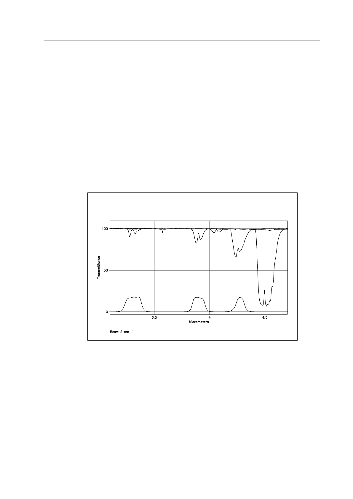
Figure 1 CO2/N2O/AA gas absorption spectra
5
Document No. 800 1005-1
Page 12
Datex-Ohmeda S/5 Anesthesia Monitor
2.1.2 O2 measurement
The differential oxygen measuring unit uses the paramagnetic principle in a pneumatic bridge
configuration. The signal picked up with a differential pressure transducer is generated in a
measuring cell with a strong magnetic field that is switched on and off at a frequency of 110 Hz.
The output signal is a DC voltage proportional to the O
gases to be measured.
Microphone
2
Electromagnet
concentration difference between the two
Mixture
out
Switched
magnetic
field
Sample in
Reference in
Figure 2 O2 measurement principle
6
Document No. 800 1005-1
Page 13
2.1.3 Agent identification
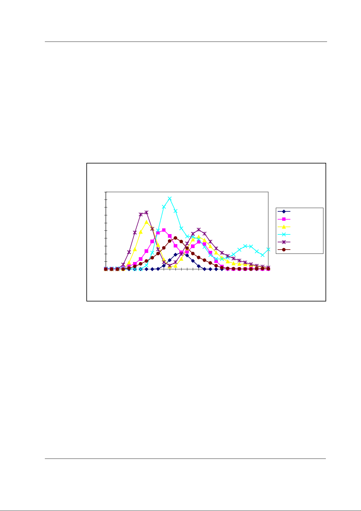
The anesthetic agent identification bench identifies Halothane, Enflurane, Isoflurane, Desflurane
and Sevoflurane.
The bench measures the spectrum of the gas between 3.24 µm and 3.39 µm. Because the
spectrum of each of the anaesthetic agents is different it is possible to identify them.
The bench consists of an infrared source, a measuring chamber, a rotating filter and a detector. The
peak wavelength of the narrow bandpass filter changes when the angle between the light path and
the filter is changed. When the filter rotates the required spectrum is scanned through. The agent or
a mixture of agents is identified by comparing the measured spectrum with stored reference
spectra.
500
450
400
350
300
250
200
150
100
50
0
S/5 Airway modules
Anesthetic Agent Gas Absorption Spectra
Halothane 0
Enflurane 0
Isoflurane 0
Sevoflurane 0
Desflurane 0
Freon 0
3246
3306
Wavelength [nm]
Figure 3 Anaesthetic Agents gas absorption spectra
3386
Document No. 800 1005-1
7
Page 14

Datex-Ohmeda S/5 Anesthesia Monitor
2.1.4 Patient Spirometry
In anesthesia, CMV (Controlled Mechanical Ventilation) is the mostly used ventilation mode. In this
mode, mechanical breaths are delivered to the patient by a ventilator with a proper tidal volume
(TV), respiration rate (RR), and inspiration/expiration ratio in time (I:E) determined by the settings of
the ventilator.
Delivery of life support gases is based on pressure. However, without knowing volume measured of
exhalation, one cannot be sure that a breath occurred. The ultimate goal of ventilation is to use the
least amount of pressure to generate the most appropriate volume for each breath.
The Patient Spirometry monitors ventilation in anesthesia. Both patient breathing circuit and the
function of the ventilator are monitored. The following parameters are displayed:
Expiratory and inspiratory tidal volume (TV) in ml.
Expiratory and inspiratory minute volume (MV) in l/min.
Expiratory volume in first second (V1.0) in per cent for adults and in 0.5 seconds for children.
Inspiration/expiration ratio in time (I:E)
Airway pressures: Peak pressure (P
pressure (PEEP), Real time airway pressure waveform (P
Flow: Real time flow waveform (V')
Compliance (C)
Pressure volume loop
Flow volume loop
), End inspiratory pressure (P
peak
)
aw
), Positive end expiratory
plat
Airway pressure
Airway flow
PEEP, P
peak
, and P
are measured by pressure transducer on the PVX board. Atmospheric pressure
plat
is used as a reference in measurement. The pressure measurement is made from the airway part
that is closest to the patient between patient circuit and intubation tube.
The measurement is based on measuring the kinetic gas pressure and is performed using Pitot
effect. Pressure transducer is used to measure the Pitot pressure. The obtained pressure signal is
linearized and corrected according to the density of the gas. Speed of the flow is calculated from
these pressure values and TV value is then integrated. MV value is further calculated a nd averaged
using TV and RR (respiratory rate) values.
8
Document No. 800 1005-1
Page 15
Patient Spirometry sensor, D-lite
Patient Spirometry is measured with a specific sensor, D-lite or Pedi-lite.
D-lite and Pedi-lite sensors are designed to measure kinetic pressure by t wo-sided Pitot tube. The
pressure reduction caused by measuring cross is taken into account, too, especially in small flows.
Velocity is calculated from pressure difference according to Bernoulli's equation. Flow is then
determined using the calcula ted velocity.
2dP×
v=
ρ
S/5 Airway modules
(from Bernoulli's equation)
F=v A×
,
where,
F=flow (l/min)
v=velocity (m/s)
A=cross area (m
dP=pressure difference (cmH
ρ=density (kg/m
Finally the volume information is obtained by integrating the flow signal.
2.2 Main components
The airway modules consist of ACX-200 and OM-101 gas measuring units, ASX-200 agent
identification unit (G-AiO/AiOV), PVX board (G-OV/AiOV/AOV), gas sampling system, ACX
measuring board and gas mother board.
Oxygen
Measuing
Unit
Serial I/O
X4
Supply
voltages
+5 V, GND
X1
Serial I/O
2
)
3
)
O2
signal
ACX
Board
2
Signal out
Supply
voltages,
Control
ACX
Supply
serial
voltages
I/O
Gas Module CPU
O)
ACX
Bench
X1
X2
Valve
controls
ACX, ASX,
PVX serial
I/O
+5 Vref
X8
+5 VL
GND
GNDD
Lamp
Supply
Voltage
Lamp
Driver
Lamp
control
Pump control
Mod key in
X9
Lamp
control
ASX
Unit
Supply
voltages
ASX
serial
i/O
Valve controls
+15 VD, GNDD
Pump control
+15 VD, GNDD
PVX
Board
X5
Supply
voltages
PVX
serial
i/O
Valve
Driver
Pump
Driver
X1
X3
Gas pressure
and flow in
X10
+24/+32 VD
X12
+15 VD
X7
+15 VD
Fan
Valves
Pump
+5 V
+5 VL
+15 VD
+/-15 V
+24 /+32 VD
GND
GNDD
+15 V
Regulator
Figure 4 Airway module block diagram
Gas Mother Board
GND
Mod key in
X11
Module
Key
Document No. 800 1005-1
9
Page 16

Datex-Ohmeda S/5 Anesthesia Monitor
2.2.1 Gas sampling system
The gas sampling system samples the measured air to the module, and removes water and
impurities from it. A sampling line is connected to the water trap on the front panel. The pump
draws gas through the sampling line to gas measuring units. After the measurements, the gas is
exhausted from sample gas out connector on the rear panel of the module.
Water trap, D-fend
The gas sample enters the monitor through the water trap, where it is divided into two flows, main
flow and side flow (see Gas sampling system block diagram). The main flow goes into the
measuring system through a hydrophobic filter.
The side flow creates a slight sub-atmospheric pressure within the water trap container. This
facilitates gathering th e fluid removed by the hydrophobic filter.
Sampling line
The sampling line is an integral part of the total sampling system. The resistance established by the
sampling line is significant when the software determines the occlusion a nd air-leak alarm limits
during the turn-on sequence.
The Nafion
Zero valve
The small inner diameter causes fluids such as blood or mucus not to propagate within the tube, so
that when the line is clogged, it is replaced.
TM
tube
1)
A nafion tube (tubes A or B, and C: see figure 5) is used to balance the sample gas humidity with
that of ambient air. The tube will prevent errors caused by the effect of water vapor on gas partial
pressure when humid gases are measured after calibration with dry gases. It is inserted between
the water trap and the zero valve (G-AiO/A iOV) or between the zero valve and ACX-200 measuring
unit (G-O/OV/AO/AOV). The tube is also inserted between the CO
absorber and the zero valve.
2
The main flow passes through a solenoid valve before proceeding to the ACX-200 measuring unit.
This valve is activated to establish the zero points for the A CX-200 and O
measuring units at start-
2
up, at 5 minutes, and after that at regular intervals. After 1-hour monitoring, the auto-zeroing is
performed once an hour. When the valve is activated, room air is drawn through the CO
into the internal system and the gas sensors.
absorber
2
1)
10
Document No. 800 1005-1
Nafion is a trademark of Du Pont
Page 17

Gas measuring units, ACX-200 and O2 unit
After the zero valve, the gas passes through the ACX-200 and O2 measuring units. In the ACX-200
measuring unit, infrared light is passed through chambers containing the main flow gas
(measurement) and a chamber containing reference gas. The measurement is made by
determining the ratio between the two light intensities.
The oxygen sensor has two inputs. One input accepts the main flow and the other draws in room air
for reference. The sensor uses a differential pressure transducer to compare the pressure gradient
produced when both gases are exposed to an oscillating magnetic field. Both gas flows exit from a
single port.
In i model, the ASX agent identification unit is installed in parallel with the oxygen sensor . The task
of the ASX unit is to identify anesthesia agents by infrared light method used also in the ACX-200
unit.
Pressure valve
The pressure valve is used to meas ure the pressure gradient between the O2 measurement flow
and the O
filter.
reference flow. This pressure gradient reflects the condition of the D-fend water trap
2
S/5 Airway modules
Normally the pressure gradient between the O
approximately +8 mmHg. If the software detects the gradient to be between 0 and -5 mmHg, the
pressure valve will initiate pressure measurement of the reference flo w. If the gradient is greater
than -5 mmHg, the software triggers the message ’Replace Trap’.
Flow cassettes
The internal flow rates are set using flow cassettes. These cassettes are used to set the side flow
rate and the O
reference flow rate, the flow rates through the measuring units and the total flow
2
rate of the sampling system.
Sampling pump and damping chamber
The sampling pump is a vibrating membrane pump driven by a 50 Hz/12 V/0.4 A square wave
current.
The damping chamber is used to even out the pulsating flow and silence the exhaust flow.
measurement flow and the reference flow is
2
11
Document No. 800 1005-1
Page 18
Datex-Ohmeda S/5 Anesthesia Monitor
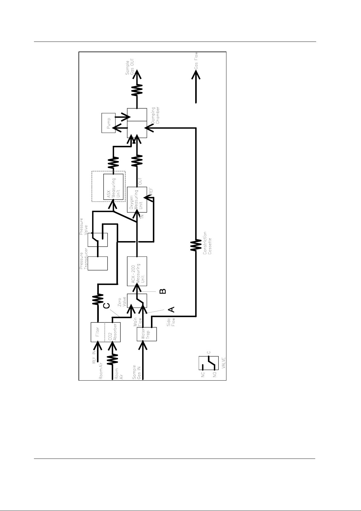
Figure 5 Gas sampling system block diagram
In G-AO, -AOV models, tube A is Teflon, B and C Nafion. In G-AiO, -AiOV models, tubes A and C are
Nafion, B is Teflon.
See new tubing since autumn 1998 in figure 7.
12
Document No. 800 1005-1
Page 19
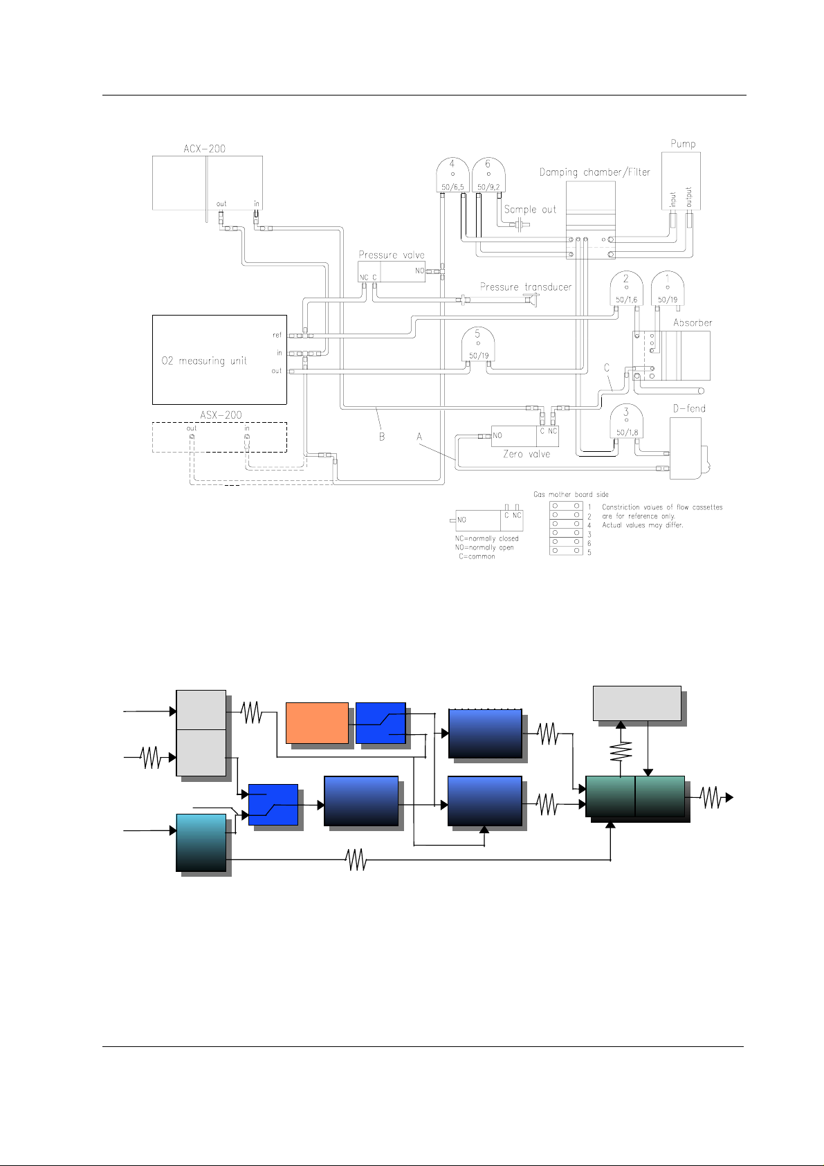
S/5 Airway modules
A
Ref IN
Room AIR
Sample
Gas IN
Figure 6 Gas sampling system layout
See new sampling system layout since autumn 1998 in figure 8.
Filter
CO
2
absorber
Pressure valve
Pressure
transducer
C
ASX-200
in G-AiO/AiOV
Sample pump
Zero valve
main flow
D-fend
B
ACX-200
O2 sensor
Damping
chamber
side flow
Constriction casse tte
Figure 7 Gas sampling system block diagram
In G-AO, -AOV models, tube A is Teflon, B and C Nafion. In G-AiO, -AiOV models, tubes A and C are
Nafion, B is Teflon. Figure 7 is valid for modules manufactured since autumn 1998.
Sample
Gas OUT
13
Document No. 800 1005-1
Page 20
Datex-Ohmeda S/5 Anesthesia Monitor
Figure 8 Gas sampling system layout
Figure 8 is valid for modules manufactured since autumn 1998.
14
Document No. 800 1005-1
Page 21

Table 2 Flow cassettes
S/5 Airway modules
Flow
Code
cassette
50/26.0 878048
50/19.0 873800
50/16.3 878047
50/15.3 873801
50/14.1 878046
50/13.1 873802
50/12.4 878045
50/11.2 874770
50/10.4 873803
50/9.2 874509
50/8.7 873804
50/7.4 873805
50/6.5 878044
50/5.8 873806
50/5.1 878043
50/4.4 873807
50/3.8 878042
50/3.2 873808
50/3.0 878040
50/2.8 878039
50/2.5 878038
50/2.3 873809
50/2.0 878037
50/1.8 873810
50/1.6 878036
50/1.4 873811
50/1.1 873812
NOTE: The number on the cassette represents relative flow when a specific pressure is applied.
Therefore 50/26.0 presents the least resistance and 50/1.1 the most.
Document No. 800 1005-1
15
Page 22
Datex-Ohmeda S/5 Anesthesia Monitor
2.2.2 ACX-200 measuring unit
The ACX photometer is of dual path type. The infrared light beam passes through a measuring
chamber containing the gas to be analyzed, and a reference chamber, which is free of CO
and AA. The measurement is made by determining the ratio between the two light intensities.
, N2O,
2
Figure 9 ACX photometer (ACX-200 measuring unit)
A filter wheel is used to control the light from an incandescent lamp that passes through the
photometer. The filters are arranged so that the light is passed sequentially:
• first at the CO
• then through the measuring chamber
• finally it is blocked completely
The same sequence is repeated at the N
absorption wavelength through the reference chamber
2
O and anaesthetic agent gas absorption wavelengths.
2
After passing through the filters the light is reflected and focused by a mirror onto the infrared
detector. This detector measures the three light levels for each gas described above.
There is an optical sensor incorporated in the photometer which detects light from a reflective
surface on the filter wheel once every revolution. The pu lses from this sensor are us ed to
synchronize the electronics to the signal from the infrared detector. A stabilizing diode measures
the temperature, which is needed to compensate for thermal drifts. The infrar ed detector, the
optical sensor and the stabilizing diode are mounted on the preamplifier board.
16
Document No. 800 1005-1
Page 23
S/5 Airway modules
Figure 10 CO2/N2O/AA measurement block diagram
2.2.3 OM measuring unit
The oxygen measurement is based on the paramagnetic susceptibility, which is a unique property
of oxygen among all gases generally present in a breathing gas mixture. The gas to be measured
and the reference gas, which usually is room air, are conducted into a gap in an electromagnet with
a strong magnetic field switched on and off at a frequency of approximately 110 Hz.
An alternating differential pressure is generated between the sample and reference inputs due to
forces acting to the oxygen molecules in a magnetic field gradient.
The pressure is measured with a sensitive differential transducer, rectified with a synchronous
detector and amplified to produce a DC voltage proportional to the oxygen partial pressure
difference of the two gases.
17
Document No. 800 1005-1
Page 24

Datex-Ohmeda S/5 Anesthesia Monitor
2.2.4 ACX measuring board
The measuring electronics can be divided into a few functional blocks, which are described below
(see the block diagram in figure 11).
The ACX Measuring board controls gas measurements. It converts the photometer signal into digital
data, calculates results and transmits it to Gas mother board. The board contains, in addition to
the 80C51FA processor, EPROM, RAM, and EEPROM, several analog and digital I/O functions.
Internal and external bus
The processor has access to the Measuring board peripherals (memory, A/D converter, D/A
converters, etc) via an internal bus. For communication between the Gas mother board and the
Measuring board, there is an external bus in connector X1.
Memory
Memory components include 64k × 8 bit EPROM program memory, 32k × 8 bit low current CMOS
RAM, and EEPROM for permanent calibration values and setup memory.
18
Document No. 800 1005-1
Page 25
S/5 Airway modules
Figure 11 ACX measuring board block diagram
19
Document No. 800 1005-1
Page 26

Datex-Ohmeda S/5 Anesthesia Monitor
2.2.5 ASX agent identification bench
The ASX-200 agent identification bench has one measuring chamber. Background compensation
is done by subtracting the background spectrum from the measured signal. Background spectrum
is measured simultaneously with the zeroing of the ACX-200 unit. The resulting spectrum is
analyzed to identify the agent.
The ASX unit requires two calibrations. One is the time between synchronization pulse and
measured spectrum (time offset) of the ASX-200 and the other is the peak wavelength of the
narrow bandpass filter. The former is calibrated automatically together with the gas calibration of
the ACX and the latter is calibrated at the factory.
Preamplifier
ASX Bord
Figure 12 ASX measuring unit
ASX preamplifier board
The absorption of infrared light is measured with a lead selenide detector. The signal is amplified
and then led to the measuring board.
2.2.6 ASX measuring board
The measuring electronics can be divided into a few functional blocks, which are described below
(See the block diagram in figure 13).
The ASX measuring board controls the measurement. It converts the ASX photometer signal to
digital data, calculates results and communicates with the main CPU through a serial channel. The
board contains, in addition to the 80C196 processor, EPROM, RAM, and EEPROM, several analog
and digital I/O functions.
Processor section
ASX Unit
Processor is a 80C196 and works at 12 MHz. It has an internal A/D-converter with a multiplexer.
One channel is used for converting temperature signal. Two others are for the measurement signal
from preamplifier board.
The processor uses an internal bus to access EPROM (64k x 8 bit), SRAM (8k x 8 bit) and two D/Aconverters. It communicates with the Gas mother board through a serial channel (RXD, TXDB).
20
Document No. 800 1005-1
Page 27

S/5 Airway modules
EEPROM is a 64 x 16 bit serial chip. It is partly protected so that if jumper X1 is installed the
processor can erase or write the protected registers by serial communication commands. The
protected section contains permanent factory calibrations.
Figure 13 ASX measuring board block diagram
21
Document No. 800 1005-1
Page 28

Datex-Ohmeda S/5 Anesthesia Monitor
2.2.7 PVX board
When Patient Spirometry is used, special sensors, D-lite or Pedi-lite, replaces the normal airway
adapter in the patient circuit. The spirometry tubing is attached to the two connectors on the sensor
and on the module front panel.
NOTE: Overpressure or negative pressure of more than 300 cmH
should never be applied.
The board is intended to perform the following tasks
• Measure the pressures in airways and the speed of breathing flow.
• Calculate tidal volume, minute volume, compliance and other useful information on patient
lungs.
Pressure transducers
There are two pressure transducers on the PVX board for airway pressure measuring purposes.
The breathing flow of a patient passing through D-lite adapter creates pressure difference. This
pressure difference is measured by pressure transducer, B1. Overpressure and negative pressure
in airways are measured by another pressure transducer B2.
NOTE: Never apply DIFFERENTIAL pressure higher than 25 cmH
sure that both spirometry tubes are always connected.
Temperature compensation
Temperature is measured by B1. This signal is used only for temperature compensation of the
pressure transducer B1 on the PVX board.
O to the flow and volume tubing
2
O to the spirometry tubing. Make
2
Data processing
After the multiplexer, the signals, PRESS, FLOW0, FLOW1, and TEMP are A/D converted for data
processing.
External communication
Communication between the PVX board and the Gas mother board is established in serial form,
using the serial channel (pins 10 and 11) of CPU on the PVX board.
22
Document No. 800 1005-1
Page 29

Figure 14 PVX board block diagram
Gas Pressure
and Flow
IN (from Front Panel)
Room Pressure
IN
Room Pressure
IN
Gas Pressure
and Flow
IN (from Front Panel)
Zero
Valve
Zero
Valve
to Gas mother bo ard
Vol
Flow
Pressure
OUT
OUT
+
-
Press
Sense
Temp sense
Press
Diff.
Sense
+
-
PRESS
MUX
TEMP
A/D
Converter
D12
Reset
from/to Gas mother board
FLOW1
+
-
A8
OFFSET
FLOW0
BUS
CPU
8051FA
D4
EPROM
MUX
D/A
Converter
EEPROM
D12
D12
D6
SRAM
Serial In
Serial Out
Document No. 800 1005-1
23
S/5 Airway modules
Page 30

Datex-Ohmeda S/5 Anesthesia Monitor
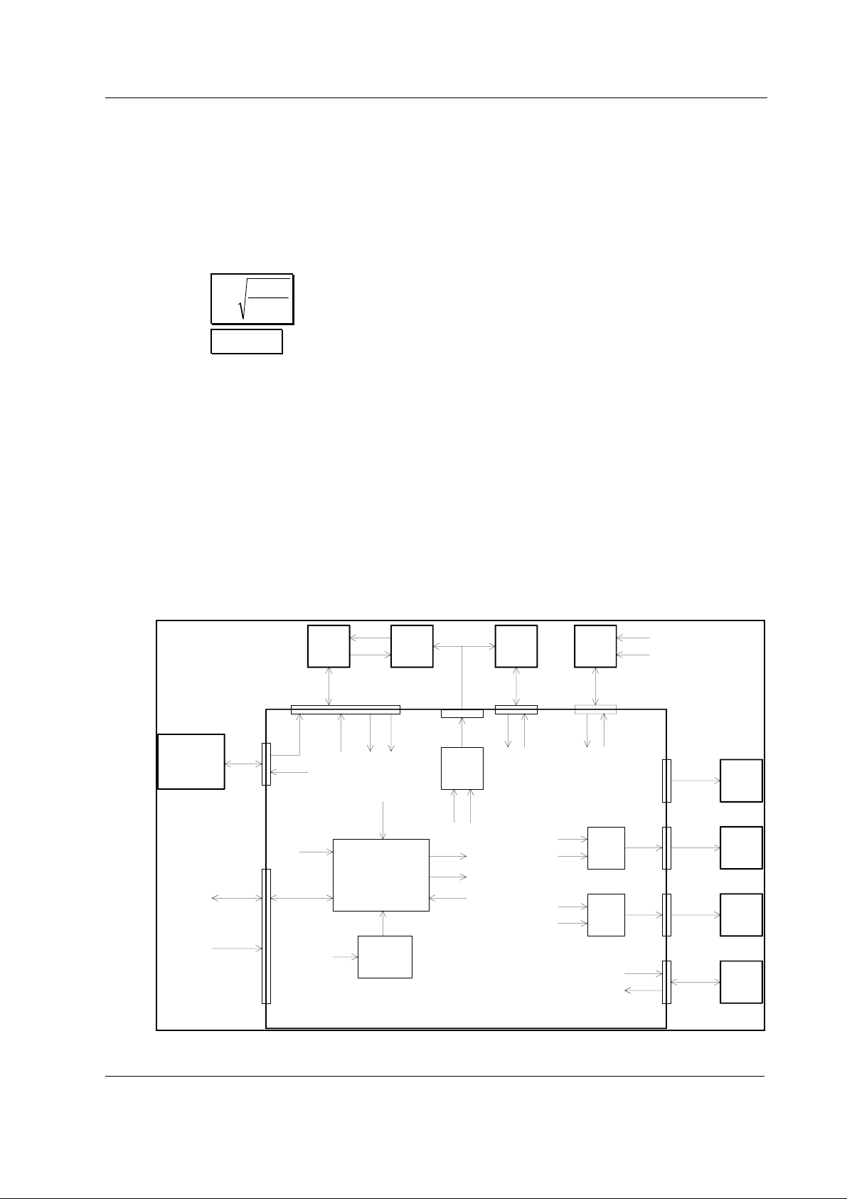
2.2.8 Gas mother board
The Gas mother board controls power supply to each measuring unit, as well as the serial
communication between the units and the module processor. There are connectors for the pump,
valves and gas measuring units on the board. The board contains a processor which controls the
functions within the module.
The tasks of the module processor are:
• to receive commands from the main CPU board and pass them on to Measuring boards.
• to gather measurement results from the Measuring boards, analyze them, and transmits
data to the main CPU board.
• to control the valves and pump based on the data which ACX Measuring board transmits.
Main parts
• Module processor 80C196KC/16 MHz
• 16 MHz oscillator
• EPROM program memory
• External RAM memory
• EEPROM
• Address and data bus latch
• Address decoding GAL-circuit
• 4-channel serial communication IC (QUART, D4)
External communication
Serial communication bus inside the module processor is used. The bus is connected to module
bus via RS-485 buffer. Transmit and reception controls of buffer are contro lled by the processor.
Connections to measuring boards
Data collection from the measuring units takes place in serial communication bus. Serial
communication lines of the measuring units are connected to QUART IC on the Gas mother board;
Channel 1 - ACX, channel 2 - ASX, channels 3 - PVX, channel 4 - not in use). The transmit side of
QUART has a buffer IC and the receipt side has a pull-up resistor.
24
Document No. 800 1005-1
Page 31

Valves, pump and infrared lamps control
Valves are controlled by ACX Measuring board from which the control signals are ran through buffer
IC to the valve connector. OCCLUS signal controls the pressure (occlusion) valve and ZERO signal
controls the zero valve.
Control signal for the pump comes from the module processor. The signal is 50 Hz pulse-width
modulated square wave. Control command is received from ACX Measuring board in serial
communication.
Control command (LAMP) of the infrared lamps of the chambers comes from the module
processor.
Key push reading
CPU reads the front panel key pushes.
Reset
Voltage supervising circuit performs power-on reset. Reset from the module bus is connected via
RS-485 buffer.
S/5 Airway modules
X4: OM
SENSOR
X2: ACX
UNIT
ZERO OCCLUS
MODULE BUS
RESET
RS-485 buffer
POWER RESET
buffer
EPROM
RAM
X5: ASX
SENSOR
SERIAL COMM. CHIP
CPURESN
Voltage
supervisor
NRESET
NRESET
X1:
AUX I/O
CPU
PUMPDRV
LAMPDRV
X3: PVX
SENSOR
buffer
LAMP DRIVER
VALVE DRIVERS
RS-485 buffer
PUMP DRIVER
ANALOG: VOL.
AWFLOW, AWPRE
MODULE BUS
SERIAL COMM.
X11: MODULE
KEYBOARD
X7: PUMP
X9: ACX. X8: ASX
LAMPS
X12: VALVES
Figure 15 Gas mother board block diagram
25
Document No. 800 1005-1
Page 32

Datex-Ohmeda S/5 Anesthesia Monitor
2.2.9 Gas interface board
The Gas interface board, B-GAS is used for connecting an Airway Module to the Central Unit.
The board connects Airway Module signals to the module bus and supplies voltages from the
module bus to the Airway Module.
On the board there is a fuse (T4A) and some capacitors to regulate the power supply.
2.3 Connectors and signals
2.3.1 Module bus connector
13
25
1
14
Pin No I/O Signal
1 I RESET RS485
2 I -15 VDC
3 I +15 VDIRTY
4 I +15VDC
5 I/O -DATA RS485
6 I/O DATA RS485
7 Ground and Shield
8 I -RESET RS485
9n/c
10 n/c
11 n/c
12 n/c
13 Ground and Shield
14 I +24/+32 VDIRTY Depends on power supply
15 I Ground DIRTY
16 n/c
17 n/c
18 n/c
19 n/c
20 I GASFR (not used)
21 I CTSD (not used)
22 I TXDD (not used)
23 O RXDD (not used)
24 I +5 VDC
25 I +5 VDC DIRTY, for infrared lamps
For B-GAS CPU Mother Board connector, see CPU Bus Connector in the Central Unit Section.
26
Document No. 800 1005-1
Page 33

2.3.2 Gas mother board connectors
X1 Module connector. Serial communication bus to the main CPU
board. Supply voltages.
X2 ACX Measuring board
X3 PVX board
X4 Oxygen measuring unit
X5 ASX Measuring board
X7 Sampling pump
X8, X9 Power supply for infrared lamps (ACX, ASX)
X10 Fan
X11 Module front panel keys
X12 Valves
S/5 Airway modules
27
Document No. 800 1005-1
Page 34

Datex-Ohmeda S/5 Anesthesia Monitor
ACX measuring board (X1) - Gas mother board (X2)
Pin No. a b c
1 +15 V NC AGND
2 -15 V NC +10 VREF
3 AOUT6 NC AOUT5 AA
4 AOUT4 VL NC AOUT3 CO
5AOUT2 O2NC AOUT1 N2O
6 DAC1 FLOW NC DAC0 PRES
7 AIN7 SAL NC ADC6 VOUT R
8 ADC5 AWL NC ADC4 VOUT IR
9ADC3 O2NC ADC2
10 ADC1 AWP NC AIN4 SSIGN
11 NC AGND NC
12 NC AGND NC
13 NC LAMP NC
14 NC PB5 NC
15 NC SSYNC NC
16 RBD2 SMOTOR NC
17 -RESET -PC0 TO RTSO
18 SEROUT 0 NC SERIN 0
19 P1.1 PC2 FGAIN 1 P1.0
20 OP0 RTSA PC3 FGAIN 2 INT0
21 SEROUT 1 PC4 OCCLUS SERIN 1
22 OP1 RTSB PC5 PUMPON IP2 TIMERIN 0
23 SEROUT 2 PC6 ZERO SERIN 2
24 NC PC7 RTS0 NC
25 NC PA0 NC
26 NC PA1 NC
27 NC PA2 NC
28 INT1 PA3 INT3
29 +5 V DRV PA4 +5 V
30 +15 VDIRTY PA5 +5 V
31 +12 V PA6 21 VAC
32 GND DIRTY PA7 ALR CALL DGND
2
NC = not connected
AIN is an AD-converter and AOUT is a DA-converter in ACX board.
ADC is an AD-converter and DAC is a DA-converter in the Gas mother board.
28
Document No. 800 1005-1
Page 35

ASX board (X5) - Gas mother board (X5)
Pin No. Signal
1 Analog ground
2N/C
3N/C
4N/C
5 +15 V
6 -15 V
7 DIRB (not used)
8RXD
9TXDB
10 N/C
11 -RESET
12 +5 V
13 +15 VDIRTY
14 Digital ground
S/5 Airway modules
29
Document No. 800 1005-1
Page 36

Datex-Ohmeda S/5 Anesthesia Monitor
PVX board (X1) - Gas mother board (X3)
Pin No. a b c
1 +15 V NC AGND
2 -15 V NC +10 VREF
3NC NCNC
4NC NCNC
5NC NCNC
6 DAC1 FLOWY NC DAC0 PRES
7 VOL NC NC
8FLOW NCNC
9NC NCNC
10 PRESS NC NC
11 NC NC NC
12 NC NC NC
13 NC NC NC
14 NC NC NC
15 NC NC NC
16 NC NC NC
17 -RESET NC NC
18 NC DIR NC
19 NC NC NC
20 NC NC NC
21 RxD NC TxDP
22 NC NC NC
23 NC NC NC
24 NC NC NC
25 NC NC NC
26 NC NC NC
27 NC NC NC
28 NC NC NC
29 NC NC +5 V
30 +15 VDIRTY NC +5 V
31 NC NC NC
32 GND DIRTY NC DGND
30
Document No. 800 1005-1
Page 37

S/5 Airway modules
3 SERVICE PROCEDURES
3.1 General service information
Field service of the airway modules is limited to replacing faulty circuit boards or mechanical parts.
The circuit boards should be returned to Datex-Ohmeda for repair.
Datex-Ohmeda is always available for service advice. Please provide the unit serial number, full
type designation, and a detailed fault description.
CAUTION Only trained personnel with appropriate equipment should perform the tests and
repairs outlined in this section. Unauthorized service may void warranty of the unit.
NOTE: After any component replacement see chapter
Adjustments and calibrations
CAUTION The ACX-200 photometer and its components are repaired/calibrated at the
factory. Attempts to repair/calibrate the unit elsewhere will adversely affect
operation of the unit. Datex-Ohmeda supplies spare ACX-200 photometers. The
information provided for the ACX-200 is for reference only.
CAUTION Due to the complicated and sensitive mechanical construction any service inside
the O
measuring unit should not be attempted.
2
CAUTION The ACX-200 Measuring board can be repaired and calibrated only at the factory.
CAUTION The PVX-100 measuring unit can be repaired only at the factory.
31
Document No. 800 1005-1
Page 38

Datex-Ohmeda S/5 Anesthesia Monitor
3.2 Service check
These instructions include complete procedures for a service check. The service check is
recommended to be performed after any service repair. However, the service check procedures can
also be used for determining possible failures.
The procedures should be performed in ascending order.
The instructions in clude a check form (
Appendix A
) which should be filled in when performing the
procedures.
The mark
? in the instructions means that the check form should be signed after performing
the procedure.
The procedures are designed for monitors with S/5 monitor software of revision 01. However, most
of the procedures also apply to monitors, which contain some other monitor software
type/revision.
3.2.1 Recommended tools
Tool Order No. Notes
Screwdrivers
Tools for blocking internal tubes
A glass of water
Flowmeter
Multimeter
Gas Interface Cable 2.5 m 884299
Sampling line 3.0 m 73319
Spirometry tube 884101
D-lite 733950
Calibration gas 755582
3.2.2 Recommended parts
Part Order No. Notes
Special tube 733383
Special tube 733382
OM ref. filter 86901
Fan filter 871558
Cable tie 64001
D-fend O-ring (2 pcs) 65312
D-fend (black) 876446
Sampling line 3.0 m 73319
Extra silicon tubing
Spare constriction cassettes
32
Document No. 800 1005-1
Page 39

All modules
S/5 Airway modules
• Remove the airway module case, the top protection cover and the bronze plate from the
side of the O
• Detach the ACX measuring board and the PVX board with the support plate, if installed.
NOTE: Wear a static control wrist strap when handling PC boards. Electrostatic discharge may
damage components on the board.
1. Check internal parts:
- screws are tightened properly
- cables are connected properly
- all IC’s that are on sockets are attached properly
- tubes are not pinched and there are no sharp bends on them
- tubes are connected properly
- there are no loose objects inside the module
sensor, if installed.
2
NOTE: Make sure that none of the tubes is in contact with the sampling pump or the O
sensor.
2
?
2. Check external parts:
- the module case is intact
- the four rubber pads under the frame are all in place
- the metal rear panel is intact
- the equipotential tap and the sample gas out connector are tightened properly
- the block screws for the gas interface cable are in place and are tightened properly
- the D-fend latch is functioning properly
?
• Install the ACX measuring board.
• Detach the D-fend.
3. Check the condition of the rubber O-rings on the metal D-fend connectors, located inside
the module front cover.
If necessary, detach the connectors by first disconnecting the tubes, then removing the
locking rings from the back of the front cover.
NOTE: The O-rings are recommended to be replaced annually.
?
4. Check the OM ref. filter (order code 86901) visually, if installed.
NOTE: The OM ref. filter is recommended to be replaced annually.
If the module does not contain the OM ref. filter, install it to prevent dirt entering the O
sensor reference channel:
2
33
Document No. 800 1005-1
Page 40

Datex-Ohmeda S/5 Anesthesia Monitor
a) shorten the thick O
to the upper part of the CO
b) connect the OM ref. filter to the loose end of the tube
c) fasten the filter to the outermost hole in the tubing plate (at the PVX board side) with a
cable tie (order code 64001)
reference channel tube by 4 centimeters (the tube that is connected
2
absorber)
2
?
• Replace the D-fend and the sampling line.
NOTE: Use only Datex-Ohmeda sampling lines in order to ensure proper functioning.
• Connect the module to the Central Unit with a long gas interface cable and switch the
monitor on.
• Configure the monitor screen so that all the needed parameters are shown, for example as
follows:
Monitor Setup
- Screen 1 Setup - Waveform Fields - Field 1 - Paw
Field 2 - Flow
Field 3 - Off
Field 4 - O2
Field 5 - AA
Field 6 - CO2
Digit Fields - Field 1 - Gases
5. Check that the module fan is running.
?
6. Wait until the message ‘Calibrating gas sensor’ disappears from the screen, then enter the
Service menu:
Monitor Setup
Take down the information regarding Airway module software.
NOTE: The PVX software string does n ot appear into the ‘Sw version/Unit id’ -list. Check PVX
software from the sticker that is located on the PVX software EPROM (if the PVX board was
installed originally).
- Install/Service
(password 16-4-34)
- Service
(password 26-23-8)
?
7. Enter the ACX service menu:
Parameters - Gas Unit - ACX
Check that the ‘Timeouts’, ‘Bad checksums’ and ‘Bad c-s by mod’ -values are not increasing
faster than by 50 per second. If one of the values is increasing faster, it indicates a failure in
module bus communication.
34
Document No. 800 1005-1
?
Page 41

S/5 Airway modules
8. If the module contains a membrane key on the front panel, press the key at least for one
second and check that it is identified, i.e. the text for Button changes from OFF to ON in the
menu.
?
• Select Halothane as anesthetic agent by first selecting AGENTS from the ACX service menu:
Agents - Select Agent - Hal - Previous Menu
9. Check that the Calib zero -value for N2O is less than 61000.
If the value exceeds the limit, it indicates bad contamination in the ACX measuring
chamber. The measuring chamber can be cleaned according to the special cleaning
instructions found in the chapter Cleaning the measuring chamber of ACX measuring unit.
However, if cleaning does not help, the whole ACX measuring unit should be exchanged.
NOTE: If the ACX measuring chamber was cleaned or the unit was replaced, then also the
tubing between the D-fend and the ACX measuring unit, including the zero valve, should be
replaced. The mentioned parts should not be cleaned.
NOTE: With monitor software S-___95 and S-___96 the Calib zero -value for N
shown as a negative value. The correct value can be calculated by adding the shown value
to the value 65536.
O is always
2
?
10. Check that the Ambient -value corresponds with the current ambient pressure (±20 mmHg).
?
11. Perform the steam test for the special tubes (Nafion), or replace the tubes.
NOTE: The special tubes are recommended to be replaced annually.
?
12. Check the CO2 absorber.
Keep the tip of the sampling line away from you and let the monitor draw in room air. Check
the “Insp CO
absorber.
” -value from the ACX service menu. If the value is less than 4, replace the CO
2
?
2
13. Check the zero valve.
Feed calibration gas into the sampling line and check that the gas readings in the service
menu correspond with the gas values on the calibration gas bottle. Keep feeding gas and
activate the zero valve from the menu. The O
other gas readings near 0 %. If the readings did not drop, replace the zero valve.
reading should drop back near 21 %, the
2
Document No. 800 1005-1
35
Page 42

Datex-Ohmeda S/5 Anesthesia Monitor
?
14. Perform the sampling system leak test.
?
15. Block the tip of the sampling line with your finger until the ‘Amb-Work’ -value becomes
stable. If the value does not reach 110, replace the sampling pump and repeat the leak
test.
?
16. Check the flow rates, adjust if necessary.
NOTE: If any of the constriction cassettes is replaced, the leak test should be repeated.
?
17. Check that the ‘Amb-Work’ -value is within 50... 75 and the OM (in-ref) -value is equal or
higher than 0. If the values differ, readjust the flows.
?
18. Check the O2 sensor output voltage.
Feed calibration gas and check that the value OM volt: mV in the menu rises at least to
2800 (3500 nominal). Adjust the O
NOTE: The voltage measurement requires module software 884295 or 885388.
If the value is not updated, measure the O
board connector X1, pin A9.
PVX boar d ACX meas. boar d
Gas mo t her boar d
ASX Me a suring un it
sensor output, if necessary.
2
sensor output voltage from the ACX measuring
2
C
B
A
19
36
Document No. 800 1005-1
The output voltage should rise at least to 2.8 V (3.5 V nominal).
?
Page 43

S/5 Airway modules
19. Perform gas calibration:
AIRWAY GAS - GAS CALIBRATION
NOTE: For maximum accuracy, a warm-up time of 30 minutes is recommended.
NOTE: If the module contains the agent identification unit, the ASX-100 or A SX-200, keep
feeding gas at least 15 seconds after the message ‘Adjust’ appears in the menu. This way
the agent identification unit has enough time for calibration.
?
• Enter the ACX service menu:
Monitor Setup
Parameters - Gas Unit - ACX
• Select Halothane as anesthetic agent:
Agents - Select Agent - Hal - Previous Menu
20. Perform the fall time measurement in the ACX service menu.
Check that the measured fall times are within the ranges that are given in the Technical
Reference Manual.
NOTE: The fall time measurement can be performed only with module software 884295 or
885388.
- Install/Service
(password 16-4-34)
- Service
(password 26-23-8) -
?
21. Perform the noise measurement.
Check that the measured noise values are within the ranges that are given in the Technical
Reference Manual.
NOTE: The noise measurement can be performed only with module software 884295 or
885388.
?
Document No. 800 1005-1
37
Page 44

Datex-Ohmeda S/5 Anesthesia Monitor
Agent identification option
22. Check that the ‘ACX_ASX Delay’ -value in the ACX service menu is within 400-800.
If the value is not within the range, readjust the flows and repeat the fall time measurement.
?
• Enter the ASX service menu:
Gas Unit - ASX
NOTE: The ASX service menu values are not updated with the anesthetic identification unit
ASX-100.
23. Feed calibration gas. When proper absorption spectrum is shown in the menu check that
the Peak normal value is close to 10.50 (±0.20). Check also that the difference between
the “Peak normal” and “Peak mirror” values is not higher than 0.30.
If the values do not meet the range, repeat the gas calibration.
?
• Set the AA identification to the automatic mode:
Agents - Select Agent - Auto - Previous Menu
24. Feed calibration gas (order code 755583) and check that the message 'Desflurane'
appears into the digit field for gases.
NOTE: The ASX-100 is not capable of identifying Desflurane.
NOTE: The ASX-100 with software 878364-1.1, or lower, is not capable of identifying
calibration gas R23 (order code 755582). Therefore, the message ‘Agent mixture’ should
appear instead.
?
38
Document No. 800 1005-1
Page 45

Patient spirometry option
• Switch the monitor off and install the PVX board, then switch the monitor back on.
• Preset gas measurement settings:
Airway Gas - Spirometry Setup - Paw Scale - 20
1. Check that the patient spirometry connectors on the front panel are clean and intact.
?
2. Connect a clean spirometry tube to the module and a clean D-lite to the other end of the
tube. Block the D-lite’s sampling line port, for example with a luer stopper.
Take the D-lite into your hand and occlude both ends tightly with your fingers (or with both
hands). Pressing firmly with the fingers creates a pressure inside the D-lite. Check that a
pressure of at least 5 cmH
NOTE: If the module has the male & female patient spirometry connectors (pediatric
option), make sure that the date marking on the D-lite is 10/94 or newer.
Flow Scale - 15
O is generated.
2
S/5 Airway modules
If the system leaks heavily, no pressure will be generated.
If there is a small leak in the connections, the monitor will measure a pressure difference
which is then interpreted as flow and seen on the monitor screen. The pressure waveform
decreases slowly and the flow waveform either goes above, or below the zero line,
depending on which of the connectors leaks.
In case of leakage, check all connections and try again.
?
3. Remove the blockage from the sampling line port and connect the sampling line. Breath
through the wider side of the D-lite. Check that the flow waveform moves downwards when
you breath in, and upwards when you breath out.
If the flow waveform moves in opposite manner, check the order of the PVX tubes inside the
module.
?
4. If possible, check the patient spirometry measurement also with the spirometry tester (order
code 884202). Follow the instructions that are supplied with the tester.
?
39
Document No. 800 1005-1
Page 46

Datex-Ohmeda S/5 Anesthesia Monitor
All Airway modules
• Switch the monitor off, disconnect the gas interface cable and reassemble the module.
NOTE: When reassembling the module, make sure that the tubes and cables are not
pinched between the PC boards and covers.
29. Clean, or replace the airway module fan filter.
?
30. Perform electrical safety check and leakage current test.
?
• Reconnect the gas interface cable and sampling line, switch the monitor on and wait until
the message ‘Calibrating gas sensor’ disappears from the screen.
31. Block the tip of the sampling line with your finger and check that the message ‘Sample line
blocked’ appears onto the monitor screen within 30 seconds.
?
32. Detach the D-fend and check that the message ‘Check D-fend’ appears onto the screen
within 30 seconds.
Reattach the D-fend.
?
• Simulate at least 5 breaths by feeding calibration gas into the sampling line.
Check that the shown gas information is correct.
33. Check that the monitor activates the APNEA -alarm within 30 seconds after you have
stopped feeding gas.
?
34. Switch the monitor off, disconnect the gas interface cable and clean the module.
?
• Fill in all necessary documents.
40
Document No. 800 1005-1
Page 47

3.3 Disassembly and reassembly
The airway module (G-AiOV) is disassem b led in the following way. See the exploded view.
1. Remove three screws from the rear panel.
2. Remove one thumb screw and one 5 mm cross recess screw from the bottom of the airway
module case.
3. Slide the case rearward and detach it from the module.
4. Lift off the top protection cover.
The PVX board can be detached by pulling sideways after two tubes are disconnected from two
valves.
The ACX measuring board can be detached by pulling sideways after a ribbon cable connector is
disconnected and a tube is pulled off from pressure transducer.
5. Remove the bronze plate from the right side of the module by pulling it up.
6. To remove the gas mother board cover, remove two front panel screws from the side of the
module, and the D-connector screws.
S/5 Airway modules
7. The front panel can be detached by removing three screws.
8. Tubing system plate with tubes and flow cassettes can be lifted off.
9. Fan can be lifted off after plastic pc board rail is detached.
Gas mother board is attached to the side of the module with screws.
The ASX unit, the ACX measuring unit, and the O
two screws each.
The pump and its magnetic shield can be removed from the chassis by unscrewing the two screws
beneath two springs at the port side of the pump.
Damping chamber/filter case can be slid out of hooks.
Reassembling is essentially reversing what was described above.
measuring unit are attached to the chassis with
2
CAUTION When reassembling the module, make sure that the tubes and cables are not
pinched between the boards and the cover.
41
Document No. 800 1005-1
Page 48

Datex-Ohmeda S/5 Anesthesia Monitor
3.4 Adjustments and calibrations
See
User’s Reference Manual
3.4.1 Gas sampling system adjustment
Flow rates should be measured and possibly adjusted under the following conditions:
• After any part within the sampling system has been replaced
• Gas response is slow
NOTE: Adjust the flows with a new, clean D-fend water trap and original Datex-Ohmeda sampling
line.
NOTE: Before adjusting the flows, make sure that there is no leakage in the sampling system.
NOTE: Let the monitor warm up for 30 minutes before measuring flow rates.
For the flow rate measur ements a flowmeter with a low flow r esistance and capability to measure
low flow rates is required. A normal length of sampling line has to be connected to the monitor as it
has a considerable effect on the flow.
for normal gas calibration instructions.
The flow rates are adjusted by changing the flow resistance cassettes (constriction cassettes) in the
sampling system. See Table 2 in chapter “
The adjustments and the respective constrictions to be adjusted are shown in the next figure, see
also chapter
manufactured since autumn 1998.
“Gas sampling system”
3.4.2 Flow rate measurement
If any flow rates are not correct, first replace the D-fend water trap. Then recheck the
incorrect flows before adjusting the flow rates.
The sampling flow rate is measured by a flowmeter at the sampling line. The rate should be
between 180 and 220 ml/min.
The sampling flow rate is adjusted by changing the flow cassette which is located between the
pump and the damping chamber.
Due to two different tubing layouts, if the described location does not contain a flow cassette, the
sampling flow rate is adjusted by changing the flow cassette that is located between the pump and
the sample gas out connector.
Gas sampling system”
to see gas sampling system block diagrams for modules
for the alternative cassettes.
42
Document No. 800 1005-1
Page 49

S/5 Airway modules
Figure 16 Gas sampling system adjustment chart
See also chapter
“Gas sampling system”
to see gas sampling system block diagrams for modules
manufactured since autumn 1998.
43
Document No. 800 1005-1
Page 50

Datex-Ohmeda S/5 Anesthesia Monitor
Rate of the side flow is checked by blocking the side flow after the water trap and measuring the
flow rate as above. The rate should decrease by 10 to 27 ml/min.
Measurement flow and reference flow of the oxygen measuring unit are checked as follows:
1. Connect the flowmeter behind the flow cassette (no. 2) ahead of the oxygen measuring unit
REF inlet. The flowmeter should show between 25 and 42 ml/min. The flow rate is adjusted
by changing the cassette.
2. Connect the flowmeter between the oxygen measuring unit IN inlet and the tube which is
connected to it. The flow rate should be between 18 and 25 ml/min larger than the REF
flow. This is adjusted by changing the flow cassettes (no. 4 and 5) which are located
between the IN and OUT inlets.
3. Flow rate of CO
absorber is measured by connecting the flowmeter to the unoccupied
2
connector of the flow cassette (no. 1). Make sure that the monitor is in normal situation
(APNEA text on the screen). The flow rate should be zero. When the gas zeroing takes place,
the rate should be between 180 and 220 ml/min. The gas zeroing can be simulated in the
ACX Service Menu manually (pump start, zero valve on). The flow rate is adjusted by
changing the cassette (no. 1).
CAUTION When changing cassettes make sure that the tubes are reconnected properly.
Flow to be adjusted Constr. No. (see figure 16) Nominal value (tolerance)
ml/min
sampling flow 6 200 (180 to 220)
side flow 3 10 to 27
O2 measurement in 4 and 5 45 to 60
O2 reference in 2 25 to 42
CO2 absorber flow 1 180 to 220 when zeroing
NOTE: Changing any of the cassettes will have some effect on the other flow rates. After any
adjustments check the other flow rates as well.
O2 measurement flow pressure
Gradual decrease of main flow rate due to the water trap filter clogging can be checked by
measuring pressure difference between the O
Remember that the sampling line should be attached to the water trap before starting the test.
The pressure difference is automatically checked after every gas zeroing.
See ACX Service menu chapter later in this manual for further information.
3.4.3 Oxygen measurement unit adjustments
The only field service procedures for the O2 measuring unit are the offset (zero), gain, and frequency
adjustments. In case of any other trouble, the measuring unit should be replaced and the faulty
one sent to Datex-Ohmeda for repair.
44
Document No. 800 1005-1
measurement flow and the O2 reference flow.
2
Page 51

Offset (zero) adjustment
Because the oxygen measuring unit is a differential sensor, which actually measures the difference
between the O
equal zero when atmospheric air is present at both inputs.
S/5 Airway modules
concentrations in the sample and reference gases, its output must be adjusted to
2
1. Connect a digital voltmeter to the output of the O
on the Gas mother board.
2. Let the monitor draw in room air and adjust the voltage to zero with the O
trim resistor designated 'ZERO' (see figure 17) in the O
potentiometers are located at the same side of the measuring unit as the tubing connectors.
3. Perform gas calibration (see
Gain adjustment
1. Adjust the O2 measuring unit offset as described in the previous section.
2. Sample 100 % oxygen and adjust the measuring unit output to between 7.7 V and 8.3 V
with the trim resistor designated 'GAIN' (see figure 17). If the output will not exceed 7.7 V, it
is acceptable that the output exceeds at least 5 V. At that level software is still able to
compensate the output.
3. Check and if necessary readjust the offset and gain until the readings remain stable.
4. Perform gas calibration (see
Temperature compensation adjustment
Factory calibrat ed.
measuring unit at pin 7 of connector X4
2
User’s Reference Manual
User’s Reference Manual
2
module PC board. The
2
).
).
measuring unit
Frequency adjustment
The switching frequency of the electromagnet of the O2 measuring unit has been selected to be
110 Hz to avoid interference from harmonics of both 50 Hz and 60 Hz mains frequency.
Fine adjustment is seldom necessary. However, if you wish to reduce the effects of mechanical
resonance peaks of the cabinet which appears as high noise level of the O
output (above 20 mV peak to peak) it is worth of trying the fine frequency adjustment. One turn of
trimmer ’FREQUENCY ’ will change the frequency by 1.5 Hz. Try to find minimum noise but do not
deviate more than
Gas calibration
The gas calibration is performed in the Airway Gas -menu. Please see
calibration.
±5 Hz.
measuring unit analog
2
User’s Reference Manual
for
45
Document No. 800 1005-1
Page 52

Datex-Ohmeda S/5 Anesthesia Monitor
OUT
Figure 17 O2 measuring unit adjustments
IN
ZERO
TEMP.COMP.
GAIN
FREQUENCY
Gas connectors
REF
Vibration insulation
3.4.4 Flow calibration
PVX board is calibrated at the factory and due to the board’s design calibration is not regularly
needed. The calibration data is saved into the board’s EEPROM memory and if the software EPROM
of the board is changed the calibration must be performed. It is recommended to perform the
calibration both with adult values using the D-lite, and with pediatric values using Pedi-lite.
1. Connect a spirometry tube with the D-lite sensor to the airway module. To improve the
accuracy, the endotracheal tube and all accessories which are in normally use should be
attached also during the calibration.
2. Enter service menu (Monitor Setup/Install Service/Service View/Modules).
3. Enter the PVX menu. After the flow is zeroed ('Zero OK' message displayed) attach
calibration pump or spirometry tester to the flow sensor (D-lite or Pedi-lite). Select the
sensor type.
4. Set the calibration volume for adult to 1000 ml and for pediatric to 300 ml.
5. Work on the calibration pump slowly, approximately 1 pump in 5 seconds, pump until
'adjust'-message appears. If you use the spirometry tester, perform the calibration
according to the tester instructions.
6. Adjust the reading to match the calibration volume (1000 ml for the D-lite and 300 ml for
the Pedi-lite).
46
Document No. 800 1005-1
Page 53

S/5 Airway modules
4 TROUBLESHOOTING
4.1 Troubleshooting chart
Trouble Possible Cause/Treatment
No response to breathing Sampling line or water trap blocked or loose, or improperly attached.
Water trap container full.
Interface cable to monitor disconnected.
See chapter “
SENSOR INOP. message The temperature is too high, check fan and filter at the rear panel.
Communication error, check timeout and bad checksum values at the service menu.
Check Airway Module connection cable and supply voltages.
Check ACX measuring board.
xx ZEROING ERROR-message Gas zeroing failed. Condensation or residual gases are affecting zero measurement. Allow module to run
drawing room air for half an hour and calibrate again.
AIR LEAK-message Air leak in sampling system. Probably water trap or the sampling line is not attached properly. Gas zero
valve failure. Pump failure or gas outlet blockage. Supply voltage missing
REPLACE TRAP-message Flow resistance increased due to residue built-up on water trap membrane. Replace the water trap.
REBREATHING-message CO2 concentration in inspiratory air is too high. Possibly CO2 absorber in ventilator is saturated. Change
the absorber.
OCCLUSION-message Sampling line or water trap is occluded. Water trap container is full. If occlusion persists check internal
tubing for blockages. Check the power supply voltages.
SELECT AGENT-message No anesthetic agent is selected though delivery is started. Vaporizer valve is broken. Traces of cleaning or
disinfecting agent in the water trap container affecting the readouts. Replace the water trap.
No response to any gas Sampling line, water trap, or internal tubing blocked or loose, or improperly attached.
Pressure valve malfunction. Pump failure. Supply voltage missing. Serial communication error. Check
those items.
Sudden increase in gas display Measuring chamber contamination.
±15 V supply voltages missing.
Water trap malfunction. Check all internal tubing and the interior of the water trap for occlusions or leaks.
Replace water trap.
Check flow rates.
Abnormally high response to all
gases (or abnormally low) or
sudden occlusion warning
Random output (resembling
noise)
Strong drift in all gases Leakage in the sampling line or internal tubing (especially in conjunction with too low readings).
No gas waveforms
intermittently.
Pressure transducer failure. Exchange the ACX Measuring board.
Chopper motor timing pulses out of sync.
Chopper motor not running, motor faulty or connection loose.
Chopper motor driver transistor C-E open circuit or current limiter short circuit.
Exchange the ACX measuring board.
Exchange the ACX measuring board.
Gas waveforms are not shown during automatic zeroing, occlusion, or air leak. Check the monitor screen
for possible messages and proceed accordingly.
Gas sampling system troubleshooting
.”
47
Document No. 800 1005-1
Page 54

Datex-Ohmeda S/5 Anesthesia Monitor
4.1.1 Supply voltage troubleshooting
Trouble Possible Cause Treatment
“Gas module removed”
No Gas module exists after turning the
monitor on.
+5V lost Gas module CPU not running. Check Gas Interface
cable.
Check +5V from module mother board and timeout
value from module service page.
Random CO2 value.
or AA response.
No CO
2
Abnormal AA mixture messages and AA
selections.
“Unknown Agent”
“Zero error” after zeroing
“Calibrate Agent ID”
“Sensor Inop”
“Continuous Occlusion”
“Sensor Inop”
Random curve trace and gas digit
values(resembling noise).
Pressure and flow curves extremely low.
CO2 value high.
“Air leak”
“Sensor Inop”
Paw and Flow curves extremely high.
“Air Leak”-message remains on the screen. +15 V dirty lost Check voltage from module mother board X1 pin 3,
Fan stopped. +32 V lost Check the fuse on Gas interface board.
+5 Vdirty lost Check the IR lamp resistance (approximately 4
Ohm)and the lamp voltage (module mother board
connectors X8 and X9)
X8 = ASX lamp(i-models)
X9 = ACX lamp
+15 V lost Check voltage from module mother board X1 pin 4,
X2 pin 1a, X3 pin 1a, X4 pin 9 and X5 pin 5.
-15 V lost Check voltage from module mother board X1 pin 2,
X2 pin 2a, X3 pin 2a, X4 pin 6 and X5 pin 6.
X2 pin30a , X3 pin 30a, X4 pin 1 and X5 pin 13.
Check the fan and regulated fan supply voltage from
module mother board connector X10.
“Calibrating gas sensor” remains on the
screen.
48
Document No. 800 1005-1
One or more of the voltages lost:
+5 Vdirty, +15 V,-15 V, +15 Vdirty
ACX measuring board not
communicating with the Gas
mother board.
ACX measuring unit badly
contaminated.
Check those voltages as above.
Check whether the ACX software version is available
in the service menu. If not, replace the ACX
measuring board.
Replace the ACX measuring unit.
Page 55

S/5 Airway modules
4.2 Gas sampling system troubleshooting
The faults which can occur in the sampling system are: leaks or blockages in the tubing, failure of
the sampling pump or the magnetic valves, or diminishing of the flow rates because of pump aging
or dirt accumulating in the internal tubing.
The following checks should help in localizing the fault. Whenever suspecting the sampling system
and always after working on the sampling system check and if necessary adjust the flow rates.
The sampling system details are illustrated in figures 5, 6, 7 and 8.
CAUTION The special internal sample tube is mechanically fragile. Sharp bends will cause
leaks.
NOTE: D-fend water trap should be replaced when the OCCLUSION message appears during the
monitor startup.
NOTE: If any liquid has entered the ACX-200 measuring unit due to water trap filter failure, contact
Datex-Ohmeda technical services.
4.2.1 Sampling system leak test
Connect power cord and sampling line. Turn the power on and wait until the initialization is over.
1. Choose ACX service data page in the Gas unit service menu.
2. Connect a tube to the sample out connector and drop its other end into a glass of water.
3. Block the sample inlet, reference flow of the oxygen measuring unit, and the CO
port that draws room air in. Wait for one minute.
There should be less than 1 bubble per 10 seconds coming out of the tube. Bubble should
not move upwards more than 11 mm per 30 seconds inside the tube. If it does, there is a
leak between the pump and the sample out connector.
4. Perform leak test to the CO
leakage is the same as above.
absorber by opening zero valve. The maximum permitted
2
absorber
2
CAUTION Do not turn the pump off while performing the leak test. Negative pressure in the
sampling system will suck water in the module.
4.2.2 Water separation
1. Dip the patient end of the sampling line into water quickly (about a half second) three times
at 45 seconds' interval. After that drop the end into water and lift it up when the sampling
line is totally filled with water.
2. Check that all the water goes into the trap container and not into the monitor.
4.2.3 Steam test for the special tubes
Choose Halothane as anesthetic agent and let the monitor sample room air. Then quickly feed air
of 100 % relative humidity (for instance from a kettle in which you are boiling water) to the monitor.
If the digital reading jumps as much as 0.1 % replace the special (Nafion) tubes.
49
Document No. 800 1005-1
Page 56

Datex-Ohmeda S/5 Anesthesia Monitor
4.3 OM measuring unit troubleshooting
Because of the complex and very sensitive construction of the oxygen measuring unit no repairs
should be attempted inside the unit. Instead, if the fault has been found in the measuring unit
itself, it should be replaced and the faulty unit be sent to Datex-Ohmeda for repair.
In cases of no response to O
or strong drift, check the tubing for loose connections, blockages and
2
leaks.
CAUTION Never apply overpressure to the O2 measuring unit as the pressure transducer may
be permanently damaged.
If the message ‘O2 zero error’ is displayed check the O2 measuring unit output voltage on Gas
mother board (see Section Offset adjustment).
If the adjustment range of the (software) calibration is insufficient check the O
measuring unit
2
output voltage and adjust the gain if necessary (see Section Gain adjustment).
If there are problems with O
response time check the O2 measurement flow rate and adjust it if
2
necessary (see Section Gas Sampling System Adjustments).
If the O
signal is noisy, check the measurement unit suspension. Frequency adjustment may help
2
in some cases (see Section Frequency adjustment).
4.4 ACX troubleshooting
CAUTION The measuring unit ACX-200 can be repaired and calibrated only at the factory.
The ACX troubleshooting is carried out in the General Troubleshooting scheme. The ACX testing is
explained at the ACX service information section, please refer to it.
4.4.1 Cleaning the measuring chamber of ACX measuring unit
In case the N2O “zero calibration constant” in Gas Service (ULT) or N2O “calib zero” in ACX Service
(AM/CCM) indicates contamination of the measuring chamber (value 61000 or more), or if the
software will stuck to the “calibrating gas sensor” state due to contaminatio n, it is possible to
attempt the measuring chamber cleaning. However, Datex-Ohmeda recommend exchanging the
measuring unit rather than cleaning.
The measuring chamber should first try to be cleaned by rinsing it with distilled water only. If rinsing
alone is not sufficient the cleaning can be tried with Datex-Ohmeda Cleaning Fluid (85969).
NOTE: Do not use other cleaning agents such as blood gas electrode cleaners. These may damage
the unit.
50
Document No. 800 1005-1
Page 57

Cleaning procedure
Tools needed
• 10 ml syringe
• water glass
• 2 pcs 30 cm silicon tubes with inner diameter of 3 mm
• screwdriver
1. Detach the measuring unit from the monitor or gas module.
2. Attach the silicon tubes to the tube connector on the unit.
3. Attach the 10 ml syringe to one of the tubes.
4. Place the tip of the other tube into the water glass.
5. Pour some distilled water into the glass.
6. Suck the water into the tubing with the syringe.
7. Leave for 15 minutes.
S/5 Airway modules
8. Move the syringe piston in and out 10 times.
9. Detach the tubes from the unit and empty the water from the measuring chamber.
10. Attach one silicon tube to the unit and connect the other end of the tube to the gas outlet of
the monitor or gas module.
11. Switch the monitor on and let the sample out flow dry out the unit at least for 15 minutes.
12. Attach the unit back to the monitor or gas module and switch the monitor on.
13. Let the monitor run at least 30 minutes before checking the calib zero in the service mode.
14. If the zero value is still more than 61000, repeat the procedure with the cleaning fluid.
NOTE: After cleaning with the cleaning fluid the measuring chamber must be well rinsed with
distilled water.
NOTE: The monitor will stay in “Calibr ating gas sensor” state u ntil the measuring chamber is
completely dry.
51
Document No. 800 1005-1
Page 58

Datex-Ohmeda S/5 Anesthesia Monitor
4.5 ASX agent identification unit troubleshooting
NOTE: Please read also troubleshooting section in
User’s Reference Manual
.
CAUTION The agent identification bench ASX-200 can only be repaired and calibrated only at
the factory.
Trouble Possible Cause/Treatment
AGENT MIXTURE-message when
calibration gas (Freon) is fed.
No response from ASX. Communication between ASX unit and Central Unit is lost. ASX bench disconnected or faulty.
No identification
Is the
ASX software
on the software list
on the service
wiev?
Repeat calibration.
If the module contains ASX-100, it is not capable to identify calibration gas R23, therefore the
message. However, the ASX-100 will still calibrate with R23.
Check that the motor is running.
YES
Go to ASX se rvice
view and check peak
normal value
NO
Is ASX motor
running?
YES
Check Err status in Gas
Mother board service page.
Fault in serial communicat.,
ReplaceASX board or Gas
Mother Board.
NO
Check ASX unit
supply voltages
Figure 18 ASX troubleshooting flowchart
52
Document No. 800 1005-1
Page 59

S/5 Airway modules
4.6 PVX board troubleshooting
CAUTION The measuring unit PVX-100 can be repaired and calibrated only at the factory.
NOTE: Never apply DIFFERENTIAL pressure higher than 25 cmH2O to the spirometry tubing. Make
sure that both spirometry tubes are always connected.
NOTE: Never apply overpressure or negative pressure of more than 300 cmH
O to the spirometry
2
tubing.
No spirometry
Is the
PVX software
on the software list
on the service
view?
NO
Check Err status in Gas
Mother board se rvice page.
YES
Go to PVX service
view
Figure 19 PVX board troubleshooting flowchart
NOTE: The PVX software string does not appear onto the list when using the combination of G-AOV
module and monitor software S-___94.
4.7 Gas mother board troubleshooting
Due to the complexity of the LSI circuitry there are only a few faults in the CPU digital electronics
that can be located without special equipment.
Check that the RAM, EPROM, CPU and other IC’s that are on the sockets are properly attached.
See Gas mother board service pages for more information.
4.7.1 Instructions after replacing the software or Gas mother board
After replacing the software or Gas mother board:
• perform the sampling system leak test
• check the flow rates
• perform the gas calibration
53
Document No. 800 1005-1
Page 60

Datex-Ohmeda S/5 Anesthesia Monitor
4.8 Error messages
Message Explanation
Occlusion The sample tube inside or outside the monitor is blocked or water trap is
occluded. If occlusion persists, measured gas values disappear.
Air leak - the water trap is not connected
- the gas outlet is blocked
- there is a leak in the sampling line inside the module. If air leak persists
measured gas values disappear.
Replace trap Indicates residue build-up on the water trap membrane. This decreases air
flow.
Zero valve error Opening the valve does not change working pressure enough.
Gas calibration is not available during the first 5
minutes/during occlusion/during air leak
Select agent No agent selected.
Continuous occlusion. Check sampling line and water trap. Occlusion over 40 seconds.
Air leak detected. Check water trap and sample gas out-flow.
Press normal screen to continue.
Calibration not allowed during the first 5 minutes after power up and in
mentioned situations.
Air leak over 40 seconds.
CO
2
Zero error Unsuccessful zeroing
Unstable Unsuccessful calibration
CO2 over scale CO2 signal exceeds the maximum waveform area
O
2
O2 zero error Unsuccessful zeroing
O2 over scale O2 signal exceeds the maximum waveform area
O2 Unstable Unsuccessful calibration
N2O
N2O zero error Unsuccessful zeroing
N2O Unstable Unsuccessful calibration
Ane agents
AA zero error
Zero error
AA unstable
Unstable
AA over scale AA signal exceeds the maximum waveform area
Menu messages during calibration
Zero error Unsuccessful zeroing
Adjust Calibration gas accepted and monitor is ready for adjusting the gas values
Unstable Unsuccessful calibration
Unsuccessful zeroing
Unsuccessful calibration
to match the calibration gas concentration
54
Document No. 800 1005-1
Page 61

5 SERVICE MENU
S/5 Airway modules
1. Press the Monitor Setup key.
2. Select
3. Select
4. Select
Install/Service
Service
(password 26-23-8).
(password 16-4-34).
Parameters - Gas Unit
.
55
Document No. 800 1005-1
Page 62

Datex-Ohmeda S/5 Anesthesia Monitor
5.1 Gas mother board
Service Data
Oper State
Internal operation state of the module:
0...9 function performed, if staying on, failure is indicated
10...29 Initialization
30...39 Normal operation state
40...49 Zeroing
50...59 Calibrating
ERR status
Indicates measuring unit malfunction:
GAS:
0 no error
1 error in ACX measuring system
2 error in ACX communication
10 error in ASX measuring system
20 error in ASX communication
40 error in PVX measuring system
80 error in PVX communication
Possible failure source: Gas CPU, ACX, ASX or PVX.
ACX:
0 no error
if not 0, replace ACX unit
ASX:
0 no error
if not 0, replace ASX unit
PVX:
0 no error
if not 0, replace PVX unit
56
Document No. 800 1005-1
Page 63

S/5 Airway modules
Serial Comm(unication)
Serial Communication indicates a state of serial communication between the module processor
and a measuring unit.
GAS: FFFF Continuously
ACX: FFFF Continuously
ASX: Value is for factory use only.
PVX: Value is for factory use only.
Rep status
Rep status is a four-digit number, where all digits, abcd , can have different values.
Gas rep status:
a
0 No sevoflurane or desflurane measurement available
3 ACX can measure sevoflurane and desflurane
b
0 No gas measurements available
F CO2, O2 N2O and AA measurements available
3 CO2 and O2 available
c
0 No ACX, ASX, nor PVX board running
1 ACX board running
3 ACX and ASX board running
5 ACX and PVX board running
7 ACX, ASX and PVX board running
d
0 Normal operation state
1 Occlusion
2 Air leak
4 Other sampling system error
8 Replace trap
ACX rep status:
a
empty Normal operation state
1 ACX initialization
b
empty Normal operation state
2 Occlusion
4 Air leak
c
C Normal operation state
others values used in manufacturer's testing
d
0 Normal operation state
others values used in manufacture's testing
ACX rep status FFFF continuously
57
Document No. 800 1005-1
Page 64

Datex-Ohmeda S/5 Anesthesia Monitor
PVX rep status FFFF continuously
General Status
0 Normal operation state
8000 Initialization
If not 0 or 8000, replace the gas mother board.
Timeouts is a cumulative number that indicates how many times the module has not responded to
the monitor's inquiry.
Bad checksums is a cumulative number that indicates how many times communication from the
module to monitor broke down.
Bad c-s by mod is a cumulative number that indicates how many communication errors the
module has detected.
The monitor starts counting these items at power up and resets to zero at power off. The nonzero
values do not indicate a failure, but the continuous counting indicates either serial communication
failure or module not in place.
The timeouts etc numbers should not grow faster than 50/s.
58
Document No. 800 1005-1
Page 65

5.2 ACX service menu
S/5 Airway modules
Pump ctrl Turns pump on/off
Zero valve ctrl Turns zero valve on/off
Pres valve ctrl Turns pressure valve on/off
Noise Meas Noise measurement.
Fall time Meas Fall time measurement.
Service Data
Fall time
Fall time indicates the response time of the measuring units. Select ‘Fall time meas’ from the
menu. Notice that text ‘feed’ appears under each gas. Feed the calibration gas until ev ery ‘feed’ is
replaced by ‘start’. Remove the sampling line quickly from the gas source.
Check that fall times are:
< 480 ms
O
2
< 360 ms
CO
2
O < 360 ms
N
2
AA < 520 ms
NOTE: The measurement can be performed only with the modules using module software 884295.
Noise measurement
, CO2 and N2O
O
2
Feed the calibration gas until the gas values are stabilized on screen. Start the measur ing by
selecting ‘Noise meas’ from the menu. After 10 seconds stop measuring by reselecting ‘Noise
meas’. Close the gas source. Noise values should be: O
< 100, CO2 < 20, N2O< 150.
2
AA
Select halothane for anesthetic agent. Feed the room air until gas values are stabilized. Perform the
noise measuring as above, the value should be < 20.
NOTE: The measurement can be performed only with the modules using module software 884295.
59
Document No. 800 1005-1
Page 66

Datex-Ohmeda S/5 Anesthesia Monitor
Calib zero and gain
These values are calibration constants of zero and gain for each gas. The zero values may change
at gas zeroing, the gain values a t gas calibration.
When the monitor performs gas zeroing, the main software will write zero constants for the gases
(CO
, N2O, AA, O2) to the ACX memory. If some dust (or water) has entered the measuring chamber,
2
zeroing of the gases require higher zero constants than before depending on the contamination
level. If some gas requires higher value than 65536 the unit is not able to perform the zeroing and
the message ‘XXX ZERO ERROR’ appears to the error list and the software recalls the previous zero
constant for the concerned gas. If this happens at th e initial start up the soft ware will not pass the
“calibrating gas sensor” state.
O zero point is very sensitive for the measuring chamber contamination. Therefore the zero
The N
2
constant of N
O can be utilized in observing the contamination level of the ACX measuring
2
chamber. The optimum value for the N
45000 indicating the ratio of 1:1 between the measuring and reference channel signals. The
maximum acceptable value for the N
maximum value that the main software is able to set is 65536.
Exp, Insp
Gas concentration value from the ACX measuring unit.
Pressures
Ambient is the ambient pressure measured at the initialization. Work press is the internal pressure
of sampling system measured by the ACX measuring board pressure transducer. The difference
between these two pressures is Amb-Work and if the pump is functioning, it should normally be
within 50...75.
O zero constant with new and clean measuring chamber is
2
O zero constant is 51000, for a new measuring unit. The
2
OM(in-ref) is a pressure difference between the O
measurement flow and the O2 reference flow.
2
This pressure difference is automatically checked after every gas zeroing and it should be between
5 to 10 mmHg. If the pressure difference turns negative a message ‘Replace trap’ is displayed
when the limit of -5 mmHg is exceeded.
In S-___97 and S-___98 software there is a software flaw in displaying the pres s ure differenc e, OM (in- ref). The flaw does not have any
effect on the functioning of the ACX unit. The operational limit for the ‘Replace Trap’ message is -5 mmHg as in previous S W versions.
The flaw is only in the displaying of the pressure difference value. With S-___97/98 software the pressure difference can be checked in
a following way: turn the pressure valve ON for five seconds. This enables the updating of the OM (ref) value. Turn the pressure valve OFF
and wait for five seconds. Now calculate the difference between Work press and OM (ref).
Pump, zero valve, and pressure valve are operated manually by highlighting and pushing the
ComWheel. During patient monitoring, the valves are in OFF position
ACX temp indicates temperature inside the ACX bench, and the value is typically +10
°C higher
than the prevalent room temperature.
Delays indicate the time delays within or between measurement units.
Delays are measured at the same time as fall times.
Check that the ACX_ASX delay is between 400-800.
NOTE: The measurement can be performed only with the modules using module software 884295.
Timeouts is a cumulative number that indicates how many times the module has not responded to
the monitor’s inquiry.
Bad checksums is a cumulative number that indicates how many times communication from the
module to monitor broke down.
Bad c-s by mod is a cumulative number that indicates how many communication errors the
module has detected. The monitor starts counting these items at power up and resets to zero at
power off. The nonzero values do not indicate a failure, but the continuous counting (more than 50
per second) indicates either serial communication failure or module not in place.
60
Document No. 800 1005-1
Page 67

5.3 PVX service menu
S/5 Airway modules
Service Data
Aw Pres Zero...The value of airway pressure zero is changing within the range of 1000 to 2400.
*) Aw Pres Gain...Gain of pressure measurement. This value should be fixed to 8662.
Flow Zero....The value corresponds to the pressure transducer B1 output during PVX zeroing.
Number 0 corresponds to 0 V and 4095 corresponds to 10 V. The value is typically within the range
of 100 to 4000.
Insp Flow Gain...Gain of inspired gas volume. Typically the value is between 5000 and 9000
depending on which sensor is used (adult/pediatric).
Exp Flow Gain...Gain of expired gas volume. Typically the value is between 5000 and 9000
depending on which sensor is used (adult/pediatric).
*) Common Offset...Cancels common error which is caused by pressure from the pressure
transducers. This is a transducer's own constant. The value should be between -230 and +230.
Valves...Position of zero valves.
Zeroing....Automatic zeroing is cancelled (disabled) or active (enabled).
*) NOTE: Items marked with asterisk (*) are not to be changed.
NOTE: The shown values are for the Adult module only. Changing the mode does not change the
values.
61
Document No. 800 1005-1
Page 68

Datex-Ohmeda S/5 Anesthesia Monitor
5.3.1 Flow calibration
Flow calibration
PVX board is calibrated at the factory and due to the board’s design calibration is not regularly
needed. The calibration data is saved into the board’s EEPROM memory and if the software EPROM
of the board is changed the calibration must be performed. It is recommended to perform the
calibration both with adult values using the D-lite, and with pediatric values using Pedi-lite.
1. Connect a spirometry tube with the D-lite sensor to the airway module. To improve the
accuracy, the endotracheal tube and all accessories which are in normally use should be
attached also during the calibration.
2. Enter service menu (
3. Enter the PVX menu. After the flow is zeroed (‘Zero OK’ message displayed) attach
calibration pump or spirometry tester to the flow sensor (D-lite or Pedi-lite). Select the
sensor type.
4. Set the calibration volume for adult to 1000 ml and for pediatric to 300 ml.
5. Work on the calibration pump slowly, approximately 1 pump in 5 seconds, pump until
‘adjust’-message appears. If you use the spirometry tester, perform the calibration
according to the tester instructions.
6. Adjust the reading to match the calibration volume (1000 ml for the D-lite and 300 ml for
the Pedi-lite).
NOTE: The last calibration dates are saved into the main CPU board memories.
Monitor Setup
- Install Service - Service - Parameters
).
62
Document No. 800 1005-1
Page 69

5.3.2 Temp & Hum service menu
If circumstances noticeably differ from normal, or additional accuracy is required, the use of Temp
& Humidity menu may be advisable.
S/5 Airway modules
Especially small errors in tidal values may indicate that temperature and humidity settings of the
monitor differ too much from the used system.
Room Temperature and Humidity
These are needed only in calibration procedure.
Insp Temperature
The setting regarding the temperature of inspired gas. The value is used in calculations. Change if
necessary.
Insp Humidity The setting regarding the humidity of inspired gas. The value is used in calculations. Change if
necessary.
Exp TemperatureThe setting regarding the temperature of expired gas. The value is used in calculations. Change if
necessary.
Exp Humidity The setting regarding the humidity of expired gas. The value is used in calculations. Change if
necessary.
63
Document No. 800 1005-1
Page 70

Datex-Ohmeda S/5 Anesthesia Monitor
5.4 ASX service menu
NOTE: The ASX service menu in monitor software S-xxx94 or newer supports only modules
equipped with the ASX-200.
Service Data
ID result displays the identified gas or mixture
Total % is the anesthetic agent concentration measured by ASX bench.
Rel % is the relative percentage of each measured agent in the mixture.
Noise value should be less than 80. Check the value only when no gas is fed and after a minimum
of one minute stabilization time.
Temp C is the temperature inside the ASX unit.
AGC (Automatic Gain Control) should be between 100 and 3500.
Motor DAC is a motor speed control voltage, 100...3900, and Motor Fluct is the speed
fluctuation, should be < 200.
Alc comp val is the compensation factor for alcohol content measured during halothane, enflurane
or isoflurane measuring. Sta shows the status of compensation, 0 means off, and 1 means on.
The value without a leading text is for factory use only.
Peak normal, Peak mirror give the place of the spectrum’s peak in the channel numbers. The peak
normal value should be 10.3- 10.7 with calibration gas R23, and 12.9-13.1 with R22. If the value
is not within the range, the gas calibration must be performed (see User’s manual for instructions).
Time offset is the time between motor synchronization pulse and filter 0° angle. Fact is the factory
value for it, EEPRO is the user calibration result, stored in the ASX, and RAM is the user calibration
result, stored in the gas mother board.
Spectrum values tell about the scales o f the spectrum display.
64
Document No. 800 1005-1
Page 71

6 SPARE PARTS
6.1 Spare parts list
NOTE: Only changed part numbers are listed under later revisions. To find the desired part: check
first the list of the revision that corresponds your device. If the part is not listed there, check the
previous revision, etc. until you find the right number.
S/5 Airway modules
6.1.1 G-AO rev. 01, G-AiO rev. 00
Item Item description Order No.
- Block screw for cables 546096
- Nafion tube (A or B, 500 mm: see manual) *733383
- Nafion tube (C, 300 mm) *733382
- Spring for D-Fend 875598
- Membrane keypad, G-AO / G-AOV 879371
- Thumb screw, AS/3 Airway Module 879511
3 Case, Airway module 878864
4 Fan 880049
6 ACX-200 measuring board *880270
65
Document No. 800 1005-1
Page 72

Datex-Ohmeda S/5 Anesthesia Monitor
Item Item description Order No.
7 Cover, top protection 878859
8 Latch for flow cassettes 880343
9 Valve, zero 58534
10 Valve, pressure *58534
11 Internal sampling tubings incl. system plate *880375
12 CO2 Absorber, Airway Module *880067
13 Damping chamber / Filter 880068
14 Gas mother board, G-AO / G-AiO *(880352) Use 885174
19 Plug, tube connector 880294
20 Front panel unit, G-AO (880374) Use 887477
20 Front panel unit, G-AiO (881116) Use 887477
21 Lamp, ASX-100/200 *878756
22 ASX-100 agent identification unit *881107
23 O2 measuring unit *(872898) Use 888511
24 Grommet for tubes 65094
25 Sample pump, (Airway module) AS/3 spare part *(881298) Use 896238
26 ACX-200 measuring unit *879849
27 Connector, sample gas out 871981
31 Cross recess screw M6x16 61678
32 Bushing, AS/3 Airway Module 879512
40 Fitting plate, G-AiO / G-AiOV / G-O / G-OV 880550
6.1.2 G-AO rev. 02, G-AiO rev. 01, G-AOV rev. 00, G-AiOV rev. 00
Item Item description Order No.
14 Gas mother board, G-AOV / G-AiOV *(881775) Use 885174
20 Front panel unit, G-AOV (880374) Use 888292
20 Front panel unit, G-AiOV (881116) Use 888292
28 PVX-100 without software *881444
29 PVX tubings 882723
30 PVX board support 880435
37 Repair set for spirometry connectors, AS/3 *886978
6.1.3 G-AO rev. 03, G-AiO rev. 02, G-AOV rev. 01, G-AiOV rev. 01
Item Item description Order No.
14 Gas mother board, AS/3 Airway module *885174
35 EMC cover, Gas mother board 884116
33 Bronze plate 884117
34 Insulation plate for 884116 879914
1)
1)
66
Document No. 800 1005-1
Page 73

S/5 Airway modules
6.1.4 G-AO rev. 04, G-AiO rev. 03, G-AOV rev. 02, G-AiOV rev. 02, G-O rev. 00, G-OV rev. 00
Item Item description Order No.
- OM reference filter 86901
- Cable tie 64001
20 Front panel unit, G-AO (885280) Use 887477
20 Front panel unit, G-AiO (885281) Use 887477
20 Front panel unit with metal SSS -connectors, AS/3 888292
20 Front panel unit w/o SSS -connectors, AS/3 887477
22 ASX-200 agent identification unit *882718
23 O2 measuring unit *888511
29 PVX tubings 885867
36 Grounding spring 885602
38 Spirometry connector, short male 886636
39 Spirometry connector, short female 886638
1)
6.1.5 G-AO rev. 05, G-AiO rev. 04, G-AOV rev. 03, G-AiOV rev. 03, G-O rev. 01, G-OV rev. 01
Item Item description Order No.
3 Case, Airway module, white 893258
* this part is recommended for stock
1)
NOTE: In case only the plastic spirometry connectors need repair, or compatibility with adult &
pediatric Patient Spirometry accessories is needed, the Repair set for spirometry connectors,
order number 886978, is recommend to be used.
The Front panel unit, order number 888292, does not contain a membrane keypad, fitting plate
and small front panel sticker. Those should be added separately according to the Airway module
type and revision.
The Flow cassette’s and their order numbers can be found listed in the section Gas sampling
system.
6.1.6 S/5 G-AO rev. 06, G-AiO rev. 05, G-AOV rev. 04, G-AiOV rev. 04
Item Item description Order No.
3 Case, Airway Module, S/5 white 898318
6.1.7 Panel stickers
Rear panel sticker set, item No. 1
Adaptation all modules
Order No.
All 894181
67
Document No. 800 1005-1
Page 74

Datex-Ohmeda S/5 Anesthesia Monitor
Front panel sticker (small), item No. 17
Adaptation G-AO, G-AOV
Order No.
-23- (Eng) 880376 880471
-26- (Fin) 888876 880471
-31- (Jpn) 888313 880471
-33- (Ger) 880546 880471
-40- (Spa) 884405 880471
-41- (Swe) 885843 880471
-42- (Dnk) 892221 880471
-43- (Fre) 880454 880471
-44- (Dut) 886065 880471
-46- (Ita) 886760 880471
-47- (Nor) 893574 880471
-48- (Por) 895256 880471
Front panel sticker (large), item No. 18
Airway Module Order No.
G-AO 880377
G-AiO 880472
G-AOV (rev. 00-01) 880472
G-AOV (Jpn) 888314
G-AOV (rev. 02) 886980
G-AiOV (rev. 00-01) 881301
G-AiOV (rev. 02) 886981
G-AiOV (rev. 02, Jpn) 890710
G-O 885233
G-OV 886972
G-OV (Jpn) 890712
other modules
Order No.
6.1.8 S/5 panel stickers
Rear panel stickers, item No. 1
Adaptation all modules
Order No.
All 8000246
68
Document No. 800 1005-1
Page 75

Front panel sticker (small), item No. 17
S/5 Airway modules
Adaptation S/5 G-AO, G-AOV
Order No.
DA 8000202 8000204
DE 8000193 8000204
EN 8000192 8000204
ES 8000196 8000204
FI 8000199 8000204
FR 8000194 8000204
IT 8000197 8000204
JA 8000389 8000204
NO 8000201 8000204
NL 8000195 8000204
PT 8000198 8000204
SV 8000200 8000204
Front panel sticker (large), item No. 18
Airway Module Order No.
G-AO 8000203
G-AiO 8000205
G-AOV 8000208
G-AOV (Jpn) 8000390
G-AiOV(Jpn) 8000391
other modules
Order No.
6.1.9 Planned Maintenance (PM) Kits:
Airway Module, G-xxx Order No.
all versions 8001762
6.1.10 Gas Interface Board, B-GAS
Item Item description Order No.
- Fuse T4A 250V *51134
- Grounding plate 885404
- Block screw for cables 546096
* this part is recommended for stock
69
Document No. 800 1005-1
Page 76

Datex-Ohmeda S/5 Anesthesia Monitor
7 EARLIER REVISIONS
This manual supports all the other Airway Module revisions except the following ones. For further
information on those revisions see corresponding manual.
Revision Manual slot/main manual Note
G-AO Module revision 01
G-AiO Module revision 00
G-AO Module revision 02
G-AiO Modules revision 01
G-AOV Module revision 01
G-AiOV Module revision 01
G-OV Module revision 01
G-O Module revision 01
Service Manual p/n 880850
Service Manual p/n 882580
Technical Reference Manual 885944-6/896624
70
Document No. 800 1005-1
Page 77

APPENDIX A, Service check form, S/5 Airway modules
APPENDIX A
71
Document No. 800 1005-1
Page 78

Datex-Ohmeda S/5 Anesthesia Monitor
72
Document No. 800 1005-1
Page 79

SERVICE CHECK FORM
S/5 Airway modules
Customer
APPENDIX A, Service check form, S/5 Airway modules
Service
Service engineer Date
OK = Test OK N.A. = Test not applicable Fail = Test Failed
All modules
OK N.A. Fail OK N.A. Fail
1. Internal parts 2. External parts
2. D-fend O-rings 3. OM ref. filter
Notes
5. Fan
6. Module soft ware
Gas Unit
Module type S/N
ACX
PVX
ASX
7. Module bus
communication
8. N2O calibration zero < 61000
9. Ambient pressure 9. Special tubes
10. CO2 absorber > 3
11. Zero valve 10. Leak test
12. Sampling pump > 109 mmHg
8. Membrane key
Document No. 800 1005-1
A-1(3)
Page 80

Datex-Ohmeda S/5 Anesthesia Monitor
16. Flow rates
Sampling flow
180-220 ml/min
Side flow 10-27 ml/min
O2 meas. in flow 45-60 ml/min
O2 ref. in flow 25-42 ml/min
CO2 absorber flow 180-220 ml/min
17. Pressures
Amb-Work
50-75 mmHg
OM (in-ref) > 4 mmHg
18. O2 sensor output voltage min. 2800 mV
OK N.A. Fail
19. Gas calibration
20. Fall time measurement
fall time < 360 ms
CO
2
O2 fall time < 480 ms
N2O fall time < 360 ms
AA fall time < 520 ms
21. Noise measur ement
noise < 20
CO
2
O2 noise < 100
N2O noise < 150
AA noise < 20
AA ID option
22. ACX_ASX Delay 400-800 ms
23. Peak normal and Peak mirror
Peak normal
10.30-10.70
Difference ±0.30
A-2(3)
Document No. 800 1005-1
Page 81

APPENDIX A, Service check form, S/5 Airway modules
OK N.A. Fail OK N.A. Fail
24. Calibration gas I.D.
Notes
Patient spirometry option
25. Spirometry connectors 26. Spirometry leak test
26. Flow waveform 27. Spirometry tester
Notes
All modules
29. Fan filter 30. Electrical safety
check
30. Occlusion detection 31. Air leak detection
31. Apnea detection 32. Final cleaning
Notes
Used spare parts
Signature
A-3(3)
Document No. 800 1005-1
Page 82

Datex-Ohmeda S/5 Anesthesia Monitor
A-4(3)
Document No. 800 1005-1
Page 83

 Loading...