

Page 1
S/5
Datex-Ohmeda Cardiac Output Modules
TM
Cardiac Output and SvO2 Module, M-COPSv (Rev. 01)
TM
S/5
Cardiac Output Module, M-COP (Rev. 03)
Technical Reference Manual Slot
Datex-Ohmeda Inc.
3030 Ohmeda Drive
53707-7550 MADISON, WIS
USA
Tel. +1-608 -221 1551, Fax +1-608-222 9147
www.us.datex-ohmeda.com
All specifications are subject to change without notice.
Document No. 800 1012-1
June 2001
Datex-Ohmeda Division,
Instrumentarium Corp.
P.O. Box 900, FIN-00031
DATEX-OHMEDA, FINLAND
Tel. +358 10 394 11 Fax +358 9 146 3310
www.datex-ohmeda.com
Instrumentarium Corp. All rights reserved.
Page 2

Page 3

Table of contents
TABLE OF CONTENTS
Cardiac Output Modules, M-COP and M-COPSv
TABLE OF CONTENTS i
TABLE OF FIGURES ii
Introduction 1
1 Specifications 2
1.1 General specifications ..............................................................................................................................2
1.2 Typical performance .................................................................................................................................2
1.2.1 C.O..................................................................................................................................................2
1.2.2 SvO
1.2.3 InvBP...............................................................................................................................................2
1.3 Technical specifications............................................................................................................................3
2 Functional Description 4
2.1 Measurement principle .............................................................................................................................4
2.1.1 Cardiac output and REF....................................................................................................................4
2.1.2 SvO
2.1.3 Invasive blood pressure measurement ..............................................................................................6
2.2 Main components.....................................................................................................................................6
2.2.1 COP board........................................................................................................................................7
2.2.2 COPSv board..................................................................................................................................10
2.3 Connectors and signals...........................................................................................................................11
2.3.1 Module bus connector....................................................................................................................11
2.3.2 Front panel connectors...................................................................................................................12
................................................................................................................................................2
2
measurement ..........................................................................................................................5
2
3 Service Procedures 14
3.1 General service information.....................................................................................................................14
3.2 Service check .........................................................................................................................................15
3.2.1 Recommended tools ......................................................................................................................15
3.3 Disassembly and reassembly..................................................................................................................20
3.4 Adjustments and calibrations..................................................................................................................20
3.4.1 Cardiac output calibration...............................................................................................................20
3.4.2 Invasive pressure calibration...........................................................................................................20
4 Troubleshooting 22
4.1 Troubleshooting charts............................................................................................................................22
4.1.1 Cardiac Output...............................................................................................................................22
4.1.2 SvO
4.1.3 InvBP.............................................................................................................................................23
4.2 Troubleshooting flowchart .......................................................................................................................24
..............................................................................................................................................22
2
5Service Menu 25
5.1 COP Menu ..............................................................................................................................................26
5.1.1 COP calibration menu.....................................................................................................................28
6 Spare Parts 29
6.1 Spare parts list .......................................................................................................................................29
Document No. 800 1012-1
i
Page 4

Datex-Ohmeda S/5 monitors
6.1.1 Cardiac Output Module, M-COP Rev. 00.......................................................................................... 29
6.1.2 Cardiac Output Module, M-COP Rev. 01.......................................................................................... 29
6.1.3 Cardiac Output Module, M-COP Rev. 02.......................................................................................... 30
6.1.4 Cardiac Output Module, M-COP Rev. 03.......................................................................................... 30
6.1.5 Cardiac Output and SvO
6.1.6 Cardiac Output and SvO
Module, M-COPSv Rev. 00 .......................................................................30
2
Module, M-COPSv Rev. 01 .......................................................................31
2
6.1.7 Front panel stickers for AS/3 modules (square buttons)...................................................................31
6.1.8 Front panel stickers for S/5 modules (round buttons).......................................................................31
7 Earlier Revisions 32
APPENDIX A 33
Service check form A-1
TABLE OF FIGURES
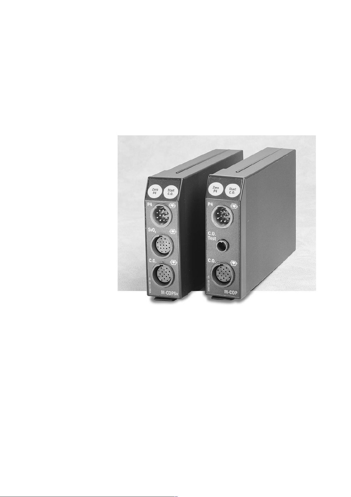
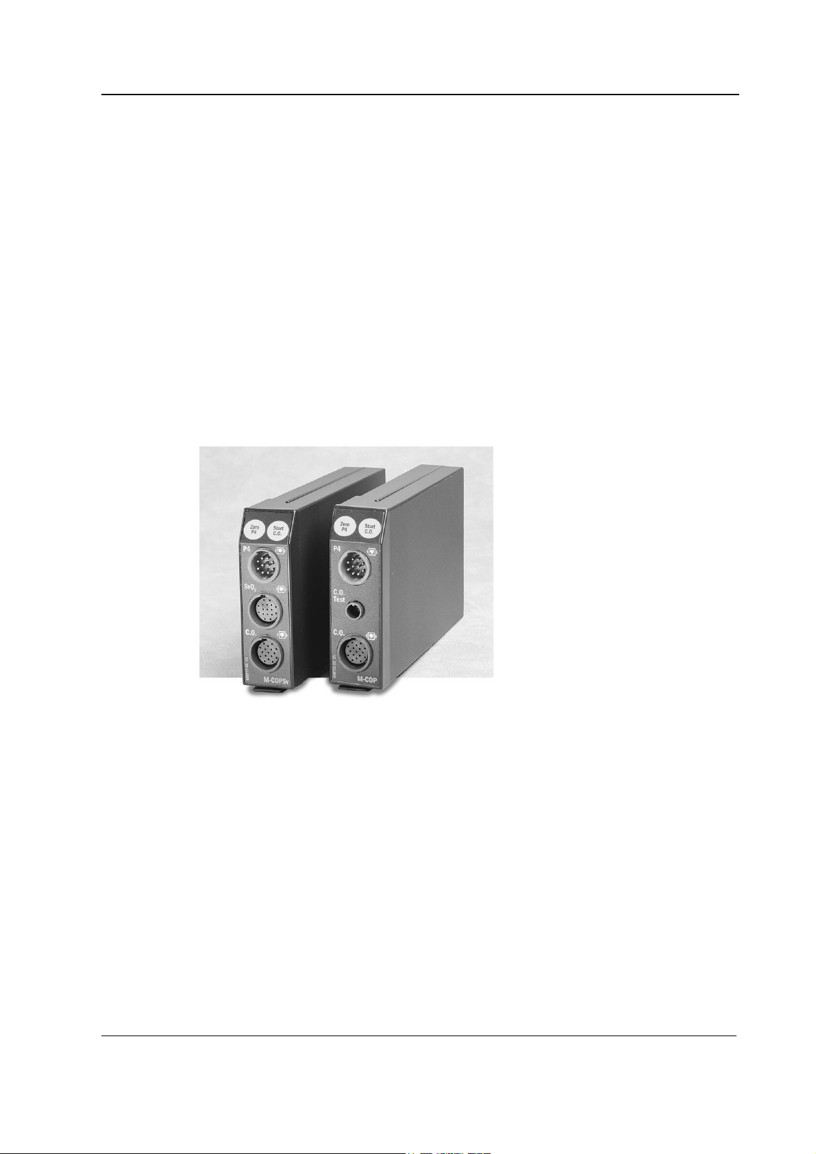
Figure 1 Cardiac Output Module, M-COP, and Cardiac Output and SvO2 Module, M-COPSv ..................................1
Figure 2 Cardiac output measurement curve.......................................................................................................5
Figure 3 Front panels of Cardiac Output Modules, M-COP and M-COPSv.............................................................. 6
Figure 4 COPSv board block diagram, on COP board the SvO
section is excluded................................................ 8
2
Figure 5 Pressure transducer principle of operation.............................................................................................8
Figure 6 Serial communication and opto isolation............................................................................................... 9
Figure 7 Cardiac Output Module troubleshooting flowchart................................................................................24
Figure 8 Module box and Cardiac Output Module, M-COP .................................................................................29
Figure 9 Cardiac Output and SvO
Module, M-COPSv........................................................................................ 30
2
ii
Document No. 800 1012-1
Page 5
INTRODUCTION
This section provides information for the maintenance and service of Cardiac Output Modules, MCOP and M-COPSv. Cardiac Output Modules, M-COP and M-COPSv are single width plug-in
modules designed for use with the S/5 monitors. Later in this manual modules can be called w/o
system name S/5.
Both modules provide
• Cardiac output (C.O.)
• Right ventricular ejection fraction (REF)
• Invasive blood pressure (InvBP) measurement
Cardiac Output Modules, M-COP and M-COPSv
Additionally, the COPSv module provides venous oxygen saturation (SvO
) measurement.
2
NOTE: Do not use identical modules in the same monitor simultaneously.These modules are
considered as identical and would cause communication errors if used in the same system.
Figure 1 Cardiac Output Module, M-COP, and Cardiac Output and SvO
COPSv
Document No. 8001012-1
Module, M-
2
1
Page 6

Datex-Ohmeda S/5 monitors
1 SPECIFICATIONS
1.1 General specifications
Module size (W × D × H) 37 × 180 × 112 mm / 1.5 × 7.1 × 4.4 in
Module weight 0.35 kg / 0.8 lbs
Power consumption, M-COP Approximately 3.5 W
Power consumption, M-COPSv Approximately 5 W
1.2 Typical performance
1.2.1 C.O.
Measurement range 0.1...20 l/min
Display resolution 0.01 l/min
Repeatability ±2 % or ±0.02 l/min whichever is greater
(measured from electrically generated flow curves)
1.2.2 SvO
2
1.2.3 InvBP
Max. change in blood temp 2.99 °C
Injectate temp range (with Edward's compatible probes)
0...25.5 °C ±0.3 °C
25.5...27.0 °C ±0.5 °C
Blood temp range (with Edward's compatible catheters)
17.5...30.9 °C ±0.5°C
31.0...43.0 °C ±0.3°C
Protection against electric shock type CF defibrillation proof
REF
Repeatability ±2 %
(Measuring range 10-60 %)
Accuracy ±2 %
(Measuring range 30-95 %)
Equal to standard deviation when using in-vivo calibration.
Measurement range -40...+320 mmHg
Zero adjustment range ±150 mmHg
Calibration range ±20 %
2
Document No. 800 1012-1
Page 7

Scales Upper limit is adjustable between 10 and 300
Sweep speed 12.5, 25, 50 mm/s
DIGITAL DISPLAY
Range -40...+320 mmHg
Resolution ±1 mmHg
WAVEFORM DISPLAY
Range -30...+300 mmHg
PULSE RATE
Measurement range 30...250 bpm
Resolution 1 bpm
Accuracy ±5 % or ±5 bpm whichever is greater
Respiration artifact rejection
1.3 Technical specifications
Cardiac Output Modules, M-COP and M-COPSv
mmHg in steps of 10. Lower limit is 10 % of selected
upper limit below zero.
The digital display is averaged over 5 seconds and updated at 5 second intervals.
Accuracy ±5 % or ±2 mmHg, whichever is greater
Transducer and 5 µV/V/mmHg, 5 VDC
input sensitivity 20 mA max current
Nonlinearity <1 %, 0 to 200 mmHg
<2 %, -40 to 0 and 200 to 320 mmHg
Filter 0...22 Hz (-3 dB),
adjustable upper limit 4...22 Hz
Zero set accuracy ±1 mmHg
Calibration resolution ±1 mmHg
Zero time < 15 sec
Protection against electric shock type CF defibrillation proof
NOTE: The accuracy of the measurement may be different from the specified accuracy, depending
on the transducer/probe used. Please check the transducer/probe specification.
Document No. 8001012-1
3
Page 8

Datex-Ohmeda S/5 monitors
2 FUNCTIONAL DESCRIPTION
2.1 Measurement principle
2.1.1 Cardiac output and REF
Cardiac output measurement is made using the principle of thermodilution. During measurement
the catheter lies in the heart, with an injection port in the right atrium (RA) and a thermistor, which
is to monitor blood temperature, in the pulmonary artery (PA). A small, known amount of thermal
indicator is injected into the RA and is mixed with the blood on its way to the PA. The catheter
thermistor measures the decrease in blood temperature as the blood flows past the thermistor in
the PA.
The information is stored in the module and the cardiac output is calculated from the area beneath
the time-temperature Cardiac Output Measurement Curve, as shown in figure 2.
The area under the time-temperature curve is inversely proportional to the flow rate which
corresponds to cardiac output.
The cardiac output is calculated from the equation:
C.O.= (1.08 C
60 Vi(TB-Ti))/(TBdt + C)
T
where:
C.O. = cardiac output in liters/minute
1.08 = factor comparing the density and specific heat of 5% dextrose solution in water to
those of blood.
= correction factor for the injectate temperature rise as it passes through the
C
T
catheter and its dead space
60 = seconds/minute
= injectate volume in liters
V
i
= baseline blood temperature (°C)
T
B
Ti = injectate temperature
dt = area under time-temperature curve between time o and x, where x is the
T
B
time when the curve has dropped to 30% of its peak value.
C = area beneath time-temperature curve between x and the end of the
curve.
4
Document No. 800 1012-1
Page 9

Cardiac Output Modules, M-COP and M-COPSv
%
-T
area A
100%
80%
start of meas.
end of meas.
area C
30%
0%
Temperature change in blood [
m.s.
80% 30%
Time
Figure 2 Cardiac output measurement curve
A = area derived by integration of the time-temperature curve
C = area beneath the time-temperature curve between t
based on an exponential fit to the curve between t
% and end of the curve. Computation
30
% of the peak and t30%.
80
REF (right ventricular ejection fraction) measurement is a part of the time-temperature
(thermodilution) cardiac output measurement. Ejection fraction is determined using an exponential
technique by synchronizing sensed R-waves with points of temperature changes on the timetemperature curve. Once ejection fraction, cardiac output, and heart rate are known, right
ventricular volumes may be calculated. The measurement requires a Baxter-Edwards fast response
thermistor catheter and an ECG module to synchronize R-wave detection to the time-temperature
curves.
t
2.1.2 SvO2 measurement
The COPSv module measures SvO2 when coupled with a Baxter-Edwards OM-2E optical module
and a Swan-Ganz oximetry catheter. To measure SvO
technique involving the use of light emitting diodes (LEDs) that produce red (660 nm) and infrared
(810 nm) light. The light is transmitted to the blood through a single plastic optical fiber in the
oximetry catheter and reflected back through a separate optical fiber to a photodetector in the
optical module. The light is electrically transmitted to the COPSv module and analyzed to
determine SvO
The oximetry portion of the system measures SvO
changes in the red blood cells. When pulses of red and infrared light are transmitted through the
oximetry catheter, the light is reflected from the red blood cells and transmitted back through the
catheter to the optical module. The amount of light reflected at each wavelength depends primarily
on the color of the blood and the number of red blood cells. Since the number of red blood cells in
the blood affects the amount of reflected light, the differences are compensated for when the
patient’s total hemoglobin value is entered. The optical module stores and transfers SvO
calibration data. SvO2 values can be affected by the presence of methemeglobin or
carboxyhemoglobin which imitate the absorption characteristics of HbO
methemeglobin or carboxyhemoglobin could then cause a falsely elevated SvO
dysfunctional hemoglobins are suspected, SvO
, the system utilizes a spectrophotometric
2
.
2
in the pulmonary artery by detecting color
2
2
. Large concentrations of
2
. In cases where
2
should be interpreted with caution.
2
5
Document No. 8001012-1
Page 10

Datex-Ohmeda S/5 monitors
2.1.3 Invasive blood pressure measurement
To measure invasive blood pressure, a catheter is inserted into an artery or vein. The invasive
pressure setup, consisting of connecting tubing, pressure transducer, an intravenous bag of normal
saline all connected together by stopcocks, is attached to the catheter. The pressure transducer is
placed at the same level with the heart, and electrically zeroed.
The pressure transducer is a piezo-resistive device that converts the pressure signal to a voltage.
The monitor interprets the voltage signal so that blood pressure data and blood pressure
waveforms can be displayed.
2.2 Main components
The Cardiac Output Module, M-COP consist of a COP circuit board and two input boards - a CO
input board and a P input board, attached to the front panel.
The Cardiac Output and SvO
boards - a CO input board, a SvO
Module, M-COPSv, consist of a COPSv circuit board and three input
2
input board and a P input board, attached to the front panel.
2
The front panels are shown in figure 3.
M-COP
1
P
4
C.O.
2
3
4
5
M-COPSv
P4
SvO
2
C.O
.
6
Figure 3 Front panels of Cardiac Output Modules, M-COP and M-COPSv
6
Document No. 800 1012-1
(1) Key for pressure zeroing (Zero P4)
(2) Key for cardiac output measurement (Start C.O.)
(3) Connector for invasive blood pressure measurement
(4) Connector for C.O. self test
(5) Connector for C.O. measurement
(6) Connector for SvO
measurement
2
Page 11

2.2.1 COP board
The COP board consists of the following functional sections.
• Processor
• Cardiac output measurement
• Cardiac output self test
• Invasive blood pressure measurement
• Serial communication
• Isolation
• Power supply
Processor section
The microprocessor uses the Intel 80C196KC-16 CPU which includes three A/D converters and a
UART. The microprocessor uses external memories, an 8-bit data bus, a 16 MHz oscillator, and a
watchdog timer. The three A/D-converters within the CPU convert the analog input signals to
digital. The internal UART communicates and transfers data between the module and the CPU
board in the monitor.
Cardiac Output Modules, M-COP and M-COPSv
Cardiac output measurement section
The catheter and the probe contain an NTC resistor that reacts to temperature change.
The temperature dependent voltage across the NTC resistor is amplified and an offset value is
added to it. The resultant signal is then regulated into a
A/D converter.
Because the temperature measurements are calibrated digitally and non-linearity of
catheter/probe is compensated by software, ambient temperature change after calibration is the
only factor that may influence the measurement.
Cardiac output self test
The Cardiac Output Module, M-COP contains a C.O. Self Test connector.
When the cable is connected to the C.O. Self Test connector, the microprocessor starts the test
program automatically. First, the microprocessor measures 30 °C, then it activates test circuits
and measures 37 °C and 41 °C.
If the values are not correct ‘Cable fault’ is displayed and there is a fault is either in the module or in
the catheter connecting cable.
±5 V range by voltage slicing and sent to an
Document No. 8001012-1
7
Page 12

Datex-Ohmeda S/5 monitors
Modul e
data
RS485
DRIVER
FOR
DATA
OPTO
ISOLATION
NON-
VOLAT ILE
MEMOR Y
SvO2 AD
OM-2 control
To opti cal module
Module bus data
SvO2
MEAS URI NG
UNI T
Modul e
reset
RS485
DRIV ER
FOR
MODU LE
RESET
Res et
Serial device
communicati on
Power f or
communication
POWER
RESET
PATIENT ISOLATION
MIC ROPROC ESSOR
RAM internal 256
external 16K
EPROM 48K
RS COMMUNICATI ON
ADCONVERTER
8 chn
12 bit
C.O.
control
C.O.
AD
C.O.
MEASURI NG
UNIT
Press AD
P4 INV
PRESSURE
MEASURING
UNIT
Power f or
module
POWER
NONISOLATION
SECTION
ISOLATION
TRANS-
FORMER
POWER
ISOLATION
SECTION
FRONT
PANEL
KEYS
Figure 4 COPSv board block diagram, on COP board the SvO2 section is excluded
Invasive blood pressure measurement section
Uin
Figure 5 Pressure transducer principle of operation
An isolated +5 V supply is connected to the input of the pressure transducer bridge circuit. From
the bridge circuit output a differential voltage, which depends on blood pressure and input supply
voltage, is calculated using the following formula:
Pressure
transducer
Uout
Input
Filter
Instrumentation
amplifier
G
to AD converter
8
Document No. 800 1012-1
Page 13

Uout = Uin x Pressure x 5 V, where Uin = 5 V Þ Uout = 25 V x Pressure [mmHg]
Pressure amplification is performed by the instrumentation amplifier. The gain of the amplifier is
set so that the level of the signal transferred to the A/D converter stays within the measurement
range even when there are circumstantial offsets or offsets caused by the pressure transducer. The
input filter before the amplifier attenuates high frequency disturbances.
A FET switch cuts the measurement current and detects the existence of the pressure transducer.
The existence of the pressure transducer is also checked digitally by a jumper next to the
connector.
Serial communication
Serial communication between the Cardiac Output Module and the Central Unit Frame is via an
RS485 type bus. The communication bus drivers are powered from the Module Bus. The module
isolation section is powered (+5 V) from the isolated power supply.
The communication drivers are controlled by a Reset signal such that when the Reset is active the
drivers do not transfer data.
In addition to the RS485 reset there is a logic power-up reset, which holds for approximately 500
ms regardless of the state of the RS485 reset. A time constant determines the power-up reset time.
The power-up reset also prevents the module from sending data to the Module Bus. The data
transmission rate is 500 kbps.
Cardiac Output Modules, M-COP and M-COPSv
Figure 6 Serial communication and opto isolation
Isolation section
There are two opto isolators, one for data and one for the reset signal. Signals are processed on
logical high-low levels even though the output of the opto isolators in the isolation section are
analog signals.
The reset line is an open collector type, with a pull-up resistor so that the microprocessor is able to
use its internal watchdog function.
Receive data
Send data
send/receive
to module prosessor
Reset
Opto isolation
Patient
Receive data
Send data
Reset
Isolation
RS485
Driver
RS485
Driver
Data
NData
send/receive
Reset in
NReset in
to central unit
(module bus)
Document No. 8001012-1
9
Page 14

Datex-Ohmeda S/5 monitors
Power supply section
The module isolated power supply is developed from the +15 Vdirty (non isolated) supply from the
Central Unit power supply.
The isolated power supply is a switched-mode circuit, where an FET switch is controlled by an
oscillator using a bipolar timer. The frequency of the oscillator is approximately 30 kHz, with a
pulse ratio of 50%; switching of the FET is slow to suppress spurious interference. A special
isolation pulse transformer is used in the circuit. The transformer secondary circuit uses normal
linear regulators except for +5 V which uses a low drop type linear regulator.
2.2.2 COPSv board
The COPSv board consists of the same functional sections as the COP board, except for the cardiac
output self test section. Additionally, the COPSv board consists of the SvO
SvO2 measurement section
The SvO2 algorithm is a part of the COPSv module software. The algorithm consists of five different
parts; initialization, calibrations, signal processing and SvO
and signal quality analysis.
measurement section.
2
calculation, automatic gain control,
2
Initialization
When the optical module is connected to the COPSv module, a number of start-up procedures are
performed prior to normal operation. These procedures include transfer of calibration factors from
the optical module to the COPSv module and initialization of LED currents.
Calibration
The system is calibrated according to either in-vitro or in-vivo calibration. In-vitro calibration is
performed before the oximetry catheter is removed from the package with the catheter tip still
inside the calibration cup. The resulting calibration factor is calculated on the basis of the
measured ratio of red and infrared signals and the ideal ratio for the calibration cup. In-vivo
calibration is performed when the catheter is inserted into the patient’s pulmonary artery. The
resulting calibration factor is based on the measured ratio of red and infrared signal and the Hgb
and SvO
calibration is used instead and the “Not calibrated” message is displayed in the SvO
Signal processing and SvO
values measured in a laboratory. If the calibration is skipped, the result of an old
2
number field.
2
calculation
2
The reflected red and infrared signals transferred from the optical module to the COPSv module are
filtered, and SvO
is calculated on the basis of the ratio of the two signals.
2
Automatic gain control
The intensity of the red and infrared signals can be amplified by four different gains. The gain is
selected automatically to achieve optimal signal levels.
Signal quality
The reflected red and infrared signals are checked for wall contact artifacts, pulsatility and intensity
shifts. An index is calculated to indicate the signal quality. 0 indicates a normal signal, 1 indicates
an intermediate signal, 2 indicates a poor signal, and 3 indicates an unacceptable signal. Please
refer to the service menu section for more information.
10
Document No. 800 1012-1
Page 15

2.3 Connectors and signals
2.3.1 Module bus connector
Pin I/O Signal
1
13
25
1
2
14
3
4
5
6
7
8
9
10
11
12
13
14
15
16
17
18
19
20
21
22
23
24
25
I
I
I
I
I/O
I/O
I
I
O
I
O
I
I
I
O
I
O
-
-
-
I
I
Cardiac Output Modules, M-COP and M-COPSv
RESET_RS485*
-15 VDC*
+15 VDIRTY*
+15 VDC*
-DATA_RS485*
DATA_RS485*
Ground & Shield*
-RESET_RS485*
CTSB
RTSB
RXDB
TXDB
Ground & Shield*
+32 VDIRTY
GroundDIRTY*
CTSC
RTSC
RXDC
TXDC
ON/STANDBY
BIT0IN
RXDD_RS232
TXDD_RS232
+5 VDC*
+5 VDC*
*Used in the M-COP module
11
Document No. 8001012-1
Page 16

Datex-Ohmeda S/5 monitors
2.3.2 Front panel connectors
Invasive blood pressure connector (P4)
Pin Signal
1
6
3
1
2
9
4
7
0
5
8
2
3
4
5
6
7
8
9
0
Pressure 4 +
Pressure 4 Polarization - (ground)
Polarization +
Not connected
Not connected
Not connected
Not connected
Ground
Cable detection
Cardiac output connector (C.O.)
Pin Signal
12
14
13
1
2
3
10
15
11
16
9
17
4
8
6
7
5
1
2
3
4
5
6
7
8
9
10
11
12
13
14
15
16
17
C.O. Self Test connector (C.O. Test)
Pin Signal
1
4
2
3
1
2
3
4
BAB
THB
BAC
Not connected
Shield
Not connected
THD
THA
THC
BAA
Not connected
Not connected
Not connected
FL
Not connected
Not connected
Not connected
CTC
CTA
CTB
CTD
12
Document No. 800 1012-1
Page 17

SvO2 connector (SvO2)
Cardiac Output Modules, M-COP and M-COPSv
Pin Signal
1
14
15
13
12
10
2
11
9
3
16
4
5
6
17
8
7
1
2
3
4
5
6
7
8
9
10
11
12
13
14
15
16
17
IR_CATHODE
CE
SK
DATA_OUT
CHASSIS_GND
SVO2_GND
HEATER_RTN
REMOTE_OUT
+V_OPT
TEMP_SENSOR
HEATER_HI
LOCAL_OUT
REF_RTN
LED_ANODE
RED_CATHODE
DATA_IN
-V_OPT
13
Document No. 8001012-1
Page 18

Datex-Ohmeda S/5 monitors
3 SERVICE PROCEDURES
3.1 General service information
Field service of the M-COP and M-COPSv modules is limited to replacing faulty mechanical parts.
The COP board and the COPSv board cannot be replaced, and all calibrations can only be done at
the factory.
Datex-Ohmeda is always available for service advice. Please provide the unit serial number, full
type designation, and a detailed description of the fault.
CAUTION Only trained personnel with the appropriate tools and equipment should perform
the tests and repairs outlined in this section. Unauthorized service may void
warranty of the unit.
14
Document No. 800 1012-1
Page 19

3.2 Service check
These instructions include complete procedures for a service check. The service check is
recommended to be performed after any service repair. However, the service check procedures can
also be used for determining possible failures.
The procedures should be performed in ascending order.
The instructions include a check form (Appendix A) which should be filled in when performing the
procedures.
Cardiac Output Modules, M-COP and M-COPSv
The mark
the procedure.
The procedures are designed for monitors with S/5 monitor software of revision 01. However, most
of the procedures also apply to monitors, which contain some other monitor software
type/revision.
? in the instructions means that the check form should be signed after performing
3.2.1 Recommended tools
Tool Order No. Notes
Patient simulator
SvO2 simulator 890121
Pressure manometer
InvBP transducer
Catheter connecting cable
Screwdriver
All modules
• Detach the module box by removing the two screws from the back of the module. Be careful
with the loose latch and spring locking pin.
1. Check internal parts:
• screws are tightened properly
• cables are connected properly
• all socket mounted IC’s are inserted properly
• EMC covers are attached properly
• there are no loose objects inside the module
?
2. Check external parts:
15
Document No. 8001012-1
Page 20

Datex-Ohmeda S/5 monitors
• the front cover and the front panel sticker are intact
• all connectors are intact and are attached properly
• the module box, latch and spring locking pin are intact
?
• Reattach the module box and check that the latch moves properly.
• Turn the monitor on and wait until the monitoring screen appears.
• Configure the monitor screen so that all the required parameters are shown, for example :
Monitor Setup - Screen 1 Setup - Waveform Fields - Field 4 - P4
• Preset the C.O., SvO
Others - C.O. View - C.O. Setup - Scale - 1.0 °C
and InvBP measurement settings:
2
- Update Hgb - 115 g/l
SvO
2
Digit Fields - Field 4 - SvO
Injectate Volume - 10 ml
Measurement Mode - SET
2
Invasive Pressures - P4 Setup - Label - PA
3. Plug in the module. Check that it goes in smoothly and locks up properly.
?
4. Check that the module is recognized by entering the C.O. View menu:
Others - C.O. View
Check that the message “No Catheter” is shown in the middle of the menu and the message
“No cable” in the digit field for SvO
, if it is an M-COPSv module.
2
?
5. Enter the service menu:
Monitor Setup - Install/Service (password 16-4-34) - Service (password 26-23-8)
Take down the information regarding COP software by selecting SCROLL VERS and turning
the ComWheel.
?
16
Document No. 800 1012-1
6. Enter the COP module service menu:
Parameters - COP
Check that the “Timeouts”, “Bad checksums” and “Bad c-s by mod” values are not
increasing faster than by 50 per second. Check that the module memories have passed the
internal memory test, i.e. “RAM”, “ROM” and “EEPROM” all show OK.
Page 21

?
Invasive blood pressure measurement
7. Check the front panel membrane key ZERO P4.
Press the key for at least one second. Check that the key being pressed is identified, i.e. the
information on the service menu under “Button” - “P4” changes from OFF to ON.
?
8. Check that “Cable” and “Probe” for P4 show OFF. Plug a cable with an invasive blood
pressure transducer into the front panel connector P4 and check that “Cable” and “Probe”
show ON and the corresponding pressure waveform appears on the screen.
?
9. Calibrate InvBP channel P4 according to the instructions in the Technical Reference Manual.
?
Cardiac Output Modules, M-COP and M-COPSv
10. Return to the normal monitoring screen by pressing the “Normal Screen” key on the
SvO2 measurement
11. Enter the COP module service menu. Check that the SvO2 values “Meas. state”, “OM fail” and
Command Board. Check the InvBP channel with a patient simulator.
The settings and checks with a Dynatech Nevada medSim 300 Patient Simulator are:
SENSITIVITY -switch; 5 µV/V/mmHg
ECG - BASE - BPM - 60
BP - 3 - WAVE - ATM
Connect the cable from channel BP3 to module connector P4. Zero the InvBP channel P4 by
pressing the ZERO P4 key on the module front panel.
BP - 3 - WAVE - PA
Check that appropriate InvBP waveforms are shown and the InvBP value is approximately
25/10 (±2 mmHg) for channel P4 (PA).
?
“OM temp.” all show NO OM.
Turn the SvO
pulse”. Connect the simulator to the module and check that the messages “Initializing,
please wait”, “Warming up” and “Not calibrated” appear in the digit field for SvO
Initializing, please wait --> Warming up --> Not calibrated
simulator’s pulsation switch to “Medium” and the range switch to “Normal
2
.
2
Document No. 8001012-1
17
Page 22

Datex-Ohmeda S/5 monitors
Check that “Meas. state” has changed to NORMAL and “OM fail” and “OM temp.” show OK.
NOTE: “OM temp.” may show UNSTABLE at first, but the message should change to OK within
a half a minute.
?
12. Perform an In-Vitro -calibration. Keep the SvO2 simulator connected to the module and turn
the pulsation switch to “No pulse”.
Enter the SvO
Others - SvO
Highlight the CALIBRATE IN VITRO text and press the ComWheel to start the calibration. Wait
until the text “Start SvO
Turn the SvO
pressing the ComWheel again. Wait until the text “Calibrating” disappears from the digit field
for SvO
Check that the calibration date for In-Vitro calibration was updated correctly and the SvO
reading on the screen is 81 % (±2).
-menu:
2
2
” appears in the menu.
2
simulator pulsation switch to “Normal Pulse” and complete the calibration by
2
.
2
2
?
13. Turn the SvO2 simulator pulsation switch to “No pulse” and check that the message “Check
cath. position” appears in the digit field for SvO
appears in the message field within one minute.
Turn the pulsation switch to “High pulse” and check that the two messages remain on the
screen.
and the message “SvO2 poor signal”
2
Turn the pulsation switch back to “Normal pulse” and check that the messages disappear
within one minute.
?
Cardiac Output measurement
14. Check the front panel START C.O membrane key.
Enter the COP module service menu. Press the key for at least one second and check that it is
identified, i.e. the information on the service menu under “Button” - “C.O.” changes from OFF
to ON.
?
• Enter the “C.O. View” menu:
Others - C.O. View
Connect a catheter connecting cable to module connector C.O.
18
Document No. 800 1012-1
Page 23

Cardiac Output Modules, M-COP and M-COPSv
15. If the module contains the C.O. Test connector (M-COP), attach the catheter connector of the
connecting cable to the C.O. Test connector. Check that the message “Cable OK” appears on
the menu after the self-test.
No Catheter --> Self Test in Progress --> Cable OK
If the message “Cable fault” appears, exchange the cable and perform the same again.
?
16. Check the C.O. measurement with a patient simulator.
The settings and checks with a Dynatech Nevada medSim 300 Patient Simulator are:
C.O. - BASE - 37 °
WAVE
Leave the WAVE menu open on the simulator. Connect the catheter connecting cable (both
connectors) to the simulator’s C.O. box. Highlight the text START C.O. SET on the C.O. View
menu.
Press the ComWheel to start the measurement. When the text “Inject now!” appears on the
menu, select the setting 5 l/min (F3) from the medSim 300 simulator. Check that the
thermodilution curve displayed returns to the base level on the screen. Complete all 6
measurements .
All modules
NOTE: The medSim 300 simulator may give an inaccurate C.O. signal immediately after it has
been turned on and after each new simulator setting. This property of the simulator must be
taken into account when interpreting the C.O. results.
17. When the set is complete, exclude the first measurement from the average using the C.O.
View menu functions:
Edit Average - Exclude Curves - 1
Press the ComWheel to exclude the first curve. Check that each of the remaining results is
within ±2 % of the new average.
?
17. Perform an electrical safety check and a leakage current test.
?
18. Check that the module functions normally after performing the electrical safety check.
?
19. Clean the module with suitable detergent.
19
Document No. 8001012-1
Page 24

Datex-Ohmeda S/5 monitors
?
• Fill in all necessary documents.
3.3 Disassembly and reassembly
Disassemble the Cardiac Output Modules ,M-COP and M-COPSv, in the following way. (see the
exploded view of the module.
1. Remove the two screws from the back of the module.
2. Pull the module box slowly rearwards and remove it from main body. Be careful with the
loose latch and spring locking pin.
To reassemble the module, reverse the order of the disassembly steps.
CAUTION When reassembling the module, make sure that the cables are reconnected
properly.
3.4 Adjustments and calibrations
3.4.1 Cardiac output calibration
The cardiac output calibration can be performed only at the factory.
3.4.2 Invasive pressure calibration
Calibrate invasive pressure when the pressure transducer (probe) is replaced with a different type
of transducer.
1. Enter the COP service menu (
2. Enter the Calibrations menu.
Monitor Setup - Install/Service - Service - Parameters)
20
Document No. 800 1012-1
3. Connect a pressure transducer with a pressure manometer to the P4 connector. Select
Page 25

Cardiac Output Modules, M-COP and M-COPSv
‘Calibrate P4’ from the menu. Leave the transducer at room air pressure.
4. Press the ComWheel to start zeroing.
5. Supply a pressure of 100 mmHg to 300 mmHg to the transducer. The recommended
pressure is 200 mmHg.
6. Set the pressure on the display to match the pressure reading on the manometer and press
the ComWheel.
A tolerance of ±1 mmHg is allowed.
7. The text ‘calibrated’ will appear on the display.
21
Document No. 8001012-1
Page 26

Datex-Ohmeda S/5 monitors
4 TROUBLESHOOTING
4.1 Troubleshooting charts
4.1.1 Cardiac Output
Trouble Cause Treatment
NO CATHETER-message Catheter or cable not connected. Connect catheter (cable).
Catheter or cable faulty. Check by self-test. Change catheter or cable.
Blood temp out of range. Check blood temp is within range.
Tinj OFF-message No injectate temp probe. Connect probe.
Probe faulty. Change probe.
Wrong type of probe. Use Baxter compatible inj. temp probe.
Temp out of range. Check blood temp is within range.
4.1.2 SvO
2
Trouble Cause Treatment
Faulty cable Factory calibration of the optical
module corrupted.
Red or infrared transmit error, currents
cannot be adjusted to factory
defaults.
No cable No optical module connected. Connect optical module.
Insufficient signal Loose catheter connection. Check connection.
Optical module failure. Replace optical module.
Catheter kinked or damaged. Calibrate In vivo or replace catheter if necessary.
Warming up Temperature of the optical module
has not yet reached the optimum
value or optical module failure or
COPSv module failure.
Replace optical module.
Please wait. If it takes longer than 20 minutes
replace optical module or COPSv module.
Poor SvO2 signal Signal pulsatility, wall contact or
intensity shift signal quality level at 3.
22
Document No. 800 1012-1
Check number field message for problem “Check
catheter position” or “Intensity shift”.
Page 27

Cardiac Output Modules, M-COP and M-COPSv
4.1.3 InvBP
Trouble Cause Treatment
Abnormally low pressure Transducer wrongly positioned. Check mid-heart level and reposition
transducer.
No pressure Defective transducer. Check transducer.
No pressure module plugged in. Check the module.
No waveform selected on screen. To select the desired pressure waveforms
press Monitor Setup key and select modify
waveforms.
Check that the pressure transducer is
open to the patient.
Not zeroed-message Measurement on, channel not zeroed. Zero the channel.
Zeroing failed-message Unsuccessful zeroing of P4 (number
field).
Calibration failed-message Unsuccessful calibrating of P4
(number field).
Out of range ≤ 40 mmHg Measurement pressure is beyond
measurement range.
Out of range > 320 mmHg Measurement pressure is beyond
measurement range.
Possibly due to pulsating pressure
waveform. Open the transducer to room air
and zero the channel.
Offset is > 150 mmHg. Open the
transducer to room air and zero the
channel.
Defective transducer. Replace and zero
the channel.
Pulsating waveform. Turn the transducer to
sphygmomanometer and try again (zeroing
takes place first).
Gain is beyond the limits (±20 % of the
default gain) of the module. Replace the
transducer.
Check transducer level. Zero the channel.
Check transducer level. Zero the channel.
The patient may also have high blood
pressure.
Zero adj. > 100 mmHg Offset when zeroing is > 100 mmHg
(but < 150 mmHg) from the absolute
zero of the module (with default gain).
Out of range Measured pressure is beyond the
internal measurement range of the
module.
See also the troubleshooting flowchart on the next page.
Check transducer. The waveform may hit
the top and the numeric display not
shown.
The waveform hits the top and the numeric
display not shown. Check transducer and
its level. Zero the channel.
23
Document No. 8001012-1
Page 28

Datex-Ohmeda S/5 monitors
4.2 Troubleshooting flowchart
Possibly faulty
COP module
Take all modules out
of the Frame
Insert M-COP and turn
power on
Does fault
still appear?
Yes
Enter the Service menu
Module-ID
on screen?
Yes
Check front panel key
functions in Service
menu
Do they work?
Yes
No
No
Fault not in COP
module
No
Does another
module work
in the same slot?
Yes
Return module to factory
for repair
24
Document No. 800 1012-1
No
Check front panel unit
and COP board to
find culprit. Replace if
necessary
Figure 7 Cardiac Output Module troubleshooting flowchart
Page 29

5 SERVICE MENU
Cardiac Output Modules, M-COP and M-COPSv
1. Press the Monitor Setup key.
2. Select Install/Service (password 16-4-34).
3. Select Service (password 26-23-8).
4. Select Parameters.
5. Select COP.
25
Document No. 8001012-1
Page 30

Datex-Ohmeda S/5 monitors
5.1 COP Menu
COP
Record Data Record Data prints out the service data and module information (id. serial number and software
id.) on the Recorder Module, M-REC.
Service Data
P4
Gain is a coefficient to compensate for gain error. Typically the value is between 17000 and
25000. Calibrate if the zero and/or gain value is outside the ranges.
Zero indicates the offset compensation value of each parameter in the A/D converter. Usually the
value is within ±1000.
Cable shows ON when the corresponding cable is connected to the front panel and Probe shows
ON when the corresponding probe is connected to the cable.
Value shows the measured numeric values simultaneously. Pressure value is a real time value and
shown in mmHg.
Probe items Catheter (ON/OFF) and Inj. (FT, BATH, or OFF) indicate connections and Value
indicates the measured temperatures in 0.01 °C increments.
SvO2
Meas. state: Measurement status shows: No optical module (No OM) connected, initializing the
optical module (Init OM), normal measurement state (Normal) and failed module (OM fail).
26
Document No. 800 1012-1
Value is a measured SvO
Gain is the gain of the remote red and infrared signals (0, 1, 2 or 3)
Red int: Reflected red intensity
Ired int: Reflected infrared intensity
Loc red: Local red intensity
value.
2
Page 31

Cardiac Output Modules, M-COP and M-COPSv
Loc ired: Local infrared intensity
OM fail: Reason why initialization OK (OK), can’t read EEPROM of the optical module correctly
(EEPROM), can’t adjust LED current to get required local signal (Transmit).
OM temp: Temperature of the optical module OK (OK), temp under 43 °C (Under), temp over 47 °C
(Over).
Pulse SQI: Signal quality index for pulsing (low pulse/high pulse). 0 indicates a normal signal, 1
indicates an intermediate signal, 2 indicates a poor signal, and 3 indicates an unacceptable
signal.
Clipp. SQI: Signal quality index for wall artifact. 0 indicates a normal signal, 1 indicates an
intermediate signal, 2 indicates a poor signal, and 3 indicates an unacceptable signal.
Int. SQI: Signal quality index for intensity shift from previous calibration or Hgb update (intensity
decreased/increased) 0 indicates a normal signal, 1 indicates an intermediate signal, 2 indicates
a poor signal, and 3 indicates an unacceptable signal.
Button: The front panel Zero P4 and Start C.O. key functions can be confirmed by pressing the key
and checking that the relevant OFF message turns to ON.
Timeouts is a cumulative number that indicates how many times the module has not responded to
the monitor's inquiry.
Bad checksums is a cumulative number that indicates how many times communication from the
module to the monitor has failed.
Bad c-s by mod is a cumulative number that indicates how many communication errors the
module has detected.
The monitor starts counting these items at power up and resets to zero at power off. The nonzero
values do not indicate a failure, but the continuous counting (more than 50 per second) during
normal operation indicates either serial communication failure or the module is not in place.
RAM indicates the state of the external RAM memory.
ROM indicates whether the checksum at the EPROM is in accordance with the software calculated
value.
EEPROM indicates if the values stored in the permanent memory are valid.
The state is either OK, Fail or ? (module not in place or a communication error).
27
Document No. 8001012-1
Page 32

Datex-Ohmeda S/5 monitors
5.1.1 COP calibration menu
Calibrate P4
This function is for calibrating the invasive blood pressure channel P4.
The calibration requires a pressure transducer (with an appropriate cable) and a pressure
manometer.
Calibration:
1. Connect the pressure transducer with the pressure manometer to the P4 connector. Select
Calibrate P4. Leave the transducer at room air pressure.
2. Press the ComWheel to start zeroing.
3. Supply a pressure of 100 mmHg to 300 mmHg to the transducer. The recommended
pressure is 200 mmHg.
4. Set the pressure on the display to match the pressure reading on the manometer and press
the ComWheel.
28
Document No. 800 1012-1
Page 33

6 SPARE PARTS
6.1 Spare parts list
NOTE: Only changed part numbers are listed under later revisions. To find the desired part: check
first the list of the revision that corresponds your device. If the part is not listed there, check the
previous revision, etc. until you find the right number.
NOTE: Accessories are listed in the Patient Monitor Supplies and Accessories.
6.1.1 Cardiac Output Module, M-COP Rev. 00
Cardiac Output Modules, M-COP and M-COPSv
4
1
3
2
5
Figure 8 Module box and Cardiac Output Module, M-COP
Item Description Order No. Item Description Order No.
- Membrane keypad 880101 11 Metal frame 879184
1 Module box (single width) 886167 13 Cross cylinder-head screw M3x6 61721
2 Spring pin 879182 14 Cross cylinder-head screw M3x12 628700
3 Latch 879181 15 Cross cylinder-head screw M3x16 628710
4 Cross recess screw M3x8 black 616215 16 Star washer 63611
5 Front panel unit, M-COP 881191 22 C.O. Test connector, M-COP 546215
The front panel unit includes all the connectors and input boards.
6.1.2 Cardiac Output Module, M-COP Rev. 01
Item Description Order No. Item Description Order No.
10 Front panel stickers See 6.1.7 20 Protection plate 883946
19 EMC plate 884099 21 Insulation plate for 883946 884121
Document No. 8001012-1
29
Page 34

Datex-Ohmeda S/5 monitors
6.1.3 Cardiac Output Module, M-COP Rev. 02
No new spare parts.
The front panel unit includes all the connectors and input boards.
6.1.4 Cardiac Output Module, M-COP Rev. 03
No new spare parts.
The front panel unit includes all the connectors and input boards.
6.1.5 Cardiac Output and SvO2 Module, M-COPSv Rev. 00
6
7
8
9
10
11
12
Figure 9 Cardiac Output and SvO2 Module, M-COPSv
Item Description Order No. Item Description Order No.
1 Module box (single width) 886167 7 Metal frame 879184
2 Latch 879181 8 EMC plate 884099
3 Spring pin 879182 9 SvO2 cable 888546
4 Cross recess screw M3x8 black 616215 10 Cross cylinder-head screw M3x12 628700
5 Front panel unit, M-COPSv 888540 11 Membrane keypad 880101
6 Cross cylinder-head screw M3x6 61721 12 Front panel sticker see 6.1.7
The front panel unit includes all the connectors and input boards.
30
Document No. 800 1012-1
Page 35

Cardiac Output Modules, M-COP and M-COPSv
6.1.6 Cardiac Output and SvO2 Module, M-COPSv Rev. 01
No new spare parts.
The front panel unit includes all the connectors and input boards.
6.1.7 Front panel stickers for AS/3 modules (square buttons)
Items 10 and 12
Adaptation M-COP
(Rev. 02)
Order No.
DA 892213 892214
DE 880978 889550
EN 880770 887376
ES 884387 889555
FI 888871 889554
FR 881271 889551
IT 886757 889556
JA 888309 890212
NL 886064 889552
NO 893557 893558
PT 895253 895239
SV 885871 889553
M-COPSv
(Rev. 00)
Order No.
6.1.8 Front panel stickers for S/5 modules (round buttons)
Adaptation M-COP
(Rev. 03)
Order No.
DA 898732 898787
DE 898723 898778
EN 898722 898777
ES 898726 898781
FI 898729 898784
FR 898724 898779
IT 898727 898782
JA 898733 898788
NL 898725 898780
NO 898731 898786
PT 898728 898783
SV 898730 898785
M-COPSv
(Rev. 01)
Order No.
31
Document No. 8001012-1
Page 36

Datex-Ohmeda S/5 monitors
7 EARLIER REVISIONS
This manual supports all earlier Cardiac Output Module revisions.
32
Document No. 800 1012-1
Page 37

APPENDIX A, Service Check Form, M-COP/M-COPSv
APPENDIX A
33
Document No. 8001012-1
Page 38

Datex-Ohmeda S/5 monitors
34
Document No. 800 1012-1
Page 39

APPENDIX A, Service Check Form, M-COP/M-COPSv
SERVICE CHECK FORM
Cardiac Output Modules, M-COP and M-COPSv
Customer
Service
Service engineer Date
OK = Test OK N.A. = Test not applicable Fail = Test Failed
All modules
OK N.A. Fail OK N.A. Fail
1. Internal parts 2. External parts
3. Installation 4. Recognition
5. Module software
6. Communication and
memories
Notes
COP
Module type S/N
InvBP measurement
7. Membrane keys 8. External parts
9. Calibration 10. Test with patient simulator
Notes
SvO2 measurement
11. Membrane keys 12. Calibration
13. SvO
Notes
messages
2
A-1(2)
Document No. 8001012-1
Page 40

Datex-Ohmeda S/5 monitors
C.O. measurement
14. Membrane keys 15. Self test
16. Test with patient
simulator
Notes
17. Electrical safety check 18. Functioning after
electrical safety
check
19. Final cleaning
Notes
Notes
Used Spare Parts
Signature
A-2(2)
Document No. 8001012-1
 Loading...