

Page 1
Datex-Ohmeda
S/5™ Memory Module, M-MEM (Rev. 05)
Technical Reference Manual
Datex-Ohmeda Inc.
3030 Ohmeda Drive
53707-7550 MADISON, WIS
USA
Tel. +1-608-221 1551, Fax +1-608-222 9147
www.us.datex-ohmeda.com
All specifications are subject to change without notice.
Document No. 8001020-2
June 2001
Datex-Ohmeda Division,
Instrumentarium Corp.
P.O. Box 900, FIN-00031
DATEX-OHMEDA, FINLAND
Tel. +358 10 394 11 Fax +358 9 146 3310
www.datex-ohmeda.com
Instrumentarium Corp. All rights reserved.
Page 2

Page 3

Table of contents
TABLE OF CONTENTS
Memory Module, M-MEM (Rev. 04)
TABLE OF CONTENTS i
Introduction 1
1 Specifications 3
1.1 General specifications ..............................................................................................................................3
1.1.1 M-MEM............................................................................................................................................3
1.2 Technical specifications............................................................................................................................3
2 Functional Description 5
2.1 Memory Module, M-MEM..........................................................................................................................5
2.1.1 Memory board..................................................................................................................................5
2.1.2 LED board........................................................................................................................................7
3 Service Procedures 11
3.1 General service information.....................................................................................................................11
3.2 Service check .........................................................................................................................................11
3.2.1 Recommended tools ......................................................................................................................11
3.3 Disassembly and reassembly..................................................................................................................15
4 Troubleshooting 17
4.1 Troubleshooting charts............................................................................................................................17
4.1.1 Memory Module.............................................................................................................................17
4.1.2 Memory cards ................................................................................................................................17
5Service Menu 19
5.1 MemCards Status menu..........................................................................................................................20
5.2 Communication......................................................................................................................................21
6 Spare Parts 23
6.1 Spare parts list .......................................................................................................................................23
6.1.1 Memory Module, M-MEM Rev. 00 ...................................................................................................23
6.1.2 Memory Module, M-MEM Rev. 01 ...................................................................................................24
6.1.3 Memory Module, M-MEM Rev. 02 ...................................................................................................24
6.1.4 Memory Module, M-MEM Rev. 03 ...................................................................................................24
6.1.5 Front panel stickers for AS/3 modules.............................................................................................24
6.1.6 Front panel stickers for S/5 modules...............................................................................................24
7 Earlier Revisions 25
APPENDIX A 27
Service check FORM A-1
Document No. 8001020-2
i
Page 4

Datex-Ohmeda S/5 monitors
ii
Document No. 8001020-2
Page 5

INTRODUCTION
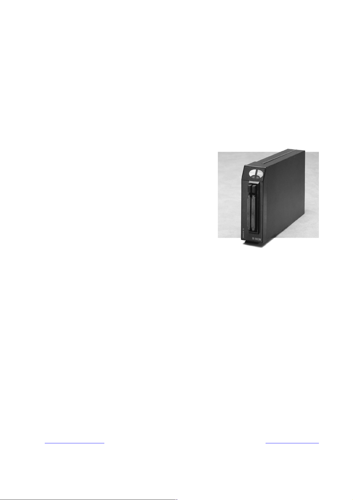
The Memory Module, M-MEM is an optional data storage single width module designed for S/5
monitors. It is used for storing patient related physiological data, discrete record keeping events,
menu configurations and user defined monitor configurations in removable PCMCIA
memory cards.
The memory module can be utilized in the following applications:
• As a backup media for patient related physiological and record keeping data.
• As a local menu server for the monitor it is attached to.
• A memory card with its previously recorded patient data can be transported to a new
• To save and load user defined monitor configurations.
The memory module is available in one version:
• Single width external plug-in Memory Module, M-MEM for S/5 Critical Care and Anesthesia
The memory module has two card slots, which use rewritable PCMCIA-ATA specification
compatible memory cards: Data and Menu Cards.
Memory Module, M-MEM
monitor location with the patient enabling continuous data collection.
monitors.
1
compatible
The data card is used for storing patient related data and record keeping events, and the menu
card is used as a storage media for pre-recorded menu configurations and user defined monitor
configuration. If the module is used only for data backup and transportation, the Menu card is not
necessarily required. Similarly, if only record keeping configurations are needed, Data card does
not have to be present. In the latter case, however, no physiological or event data can be stored in
a memory card.
2
Module software runs under MS-DOS
files created in Data and Menu MemCards are MS-DOS compatible.
1
PCMCIA = Personal Computer Memory Card International Association
2
MS-DOS is a trademark of Microsoft Corporation
3
Datalight is a trademark of Datalight, Inc.
compatible operating system provided by Datalight3. The
The communication between the monitor CPU and the memory module is performed through highspeed internal TTL level RS-232 serial interface. Data transfer rate is 76.8 kbps.
NOTE: Memory Module,M-MEM,cannot be used in the Extension Frame,F-EXT4 and in the S/5
Compact Monitors.
NOTE: Memory Module, M-MEM rev. 00-02 require software upgrade for communication with S/5
Aneshtesia and Critical Care Monitors.
Document No. 8001020-2
1
Page 6

Datex-Ohmeda S/5 monitors
2
Document No. 8001020-2
Page 7

1 SPECIFICATIONS
1.1 General specifications
1.1.1 M-MEM
Module size (W × D × H) 37 × 180 × 112 mm/1.5 × 7.1 × 4.4 in
Module weight 0.4 kg/1.0 lbs
Total power consumption 2 W maximum
1.2 Technical specifications
MemCard capacity 6 MB
Data storage capacity 2 days of continuous physiological data trends
Operating system Datalight ROM-DOS
File system MS-DOS compatible
MemCards PCMCIA-ATA compatible memory cards
Memory Module, M-MEM
Document No. 8001020-2
3
Page 8

Datex-Ohmeda S/5 monitors
4
Document No. 8001020-2
Page 9

2 FUNCTIONAL DESCRIPTION
The Memory Module, M-MEM contains memory board and a LED (Light Emitting Diode) board
attached to the front panel.
The front panel has a dual PCMCIA card connector for two MemCards. Above the card slots there
are two push buttons for removing the MemCards from the module, and two memory card specific
LEDs. The LEDs are on during memory card read and write operations to notify the user not to
remove them until the operation is complete.
2.1 Memory Module, M-MEM
2.1.1 Memory board
Processor section
Basically, memory module is a single board PC with unnecessary I/O functions removed. The
processor is Intel 80C186 compatible and the software runs under DOS operating system.
Operating frequency is 16 MHz. The board has 512 kB RAM, 448 KB ROM, 128 kB EEPROM and
associated buffer circuits for memory operations.
Memory Module, M-MEM
Intel 82365SL compatible PC Card Interface Controller (PCIC) provides all the functions needed in
MemCard operations. Serial communication, EEPROM read and write operations and LED control
is accomplished through a QUART circuit. In addition, processor board contains circuitry to control
reset signals and MemCard programming voltages.
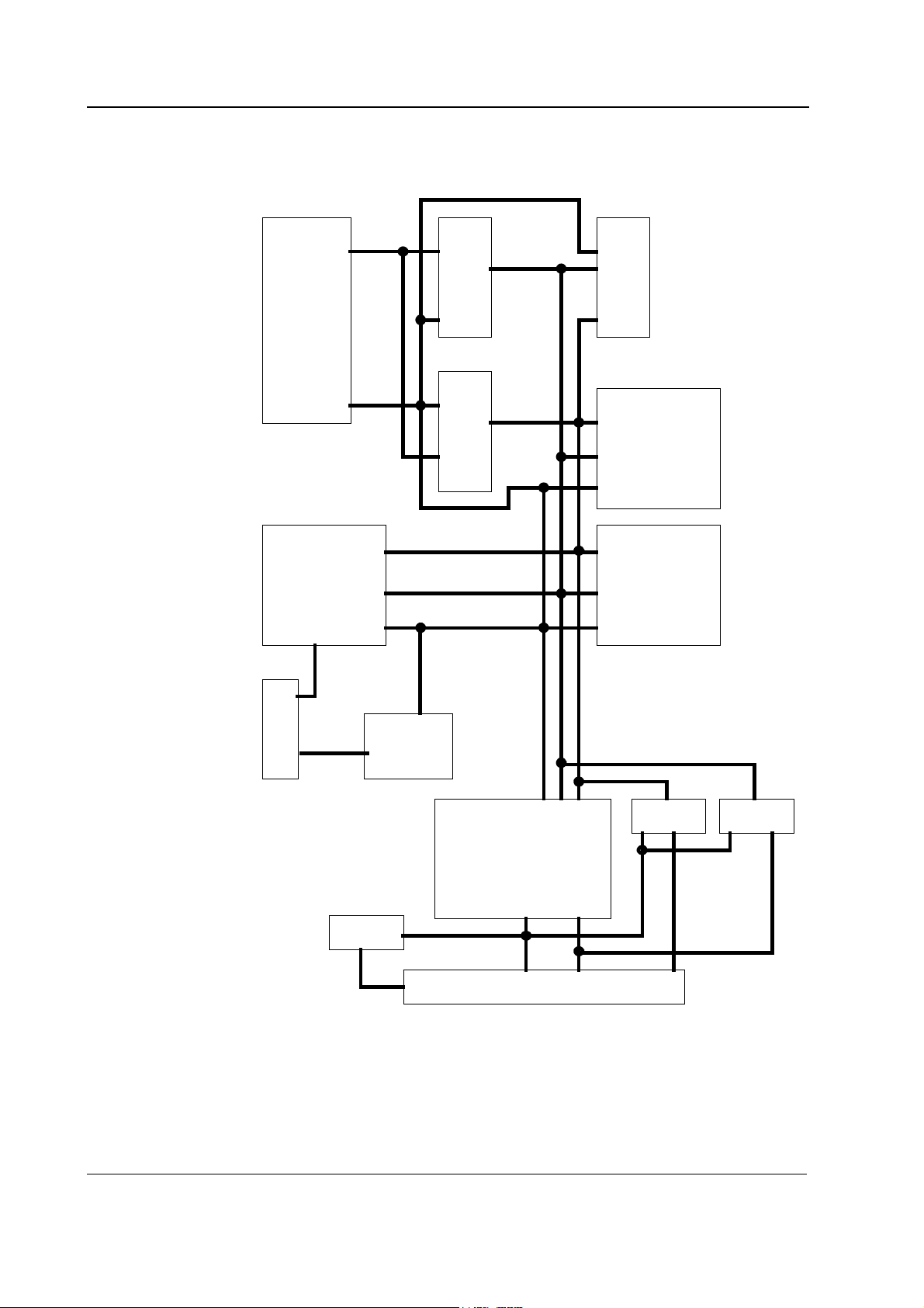
Memory module board block diagram is shown in figure 1.
PCMCIA card interface
MEM has PCMCIA compatible card sockets for two MemCards. Both sockets consist of 60 signal
and 8 power connections. MemCards are PCMCIA-ATA compatible, and their memory capacity
is 6 MB.
All MemCard read and write operations as well as card power management are controlled by PCIC
interface controller.
Card removals and insertions are also detected by the interface controller.
MemCard files are MS-DOS compatible and they can be copied for archival with any MS-DOS
compatible computer equipped with PCMCIA-ATA specification compatible card drive.
Document No. 8001020-2
5
Page 10
Datex-Ohmeda S/5 monitors
PROCESSOR
80C186X
SERIAL ,
EEPROM & LED,
CONTROL
SERIAL
COMMUNICATION
CONTROL
BUS
ADDRESS
LATCHES ADDRESS/DATA
DATA
BUFFER
BUS
DATA
BUS
ADDRESS
RECORD
CONTROL
LOGIC
0.5 MB STATIC
448KB FLASH
MEMORY
RAM
MODULE BUS
CONNECTOR
RESET,
+5V &
+12V
MEMORY CARD
POWER
CONTROL
POWER
CARD
POWER &
RESET
CONTROL
CARD CONTROLLER
CARD CONTROL
DUAL SLOT PCMCIA MEMORY
CARD CONNECTOR
PCMCIA MEMORY
Figure 1 Memory board block diagram
MEMORY
BUFFERS
CARD ADDRESS
DATA
CARD DATA
MEMORY CARD
ADDRESS
BUFFERS
6
Document No. 8001020-2
Page 11

Memory Module, M-MEM
Serial communication
Serial communication between the module and main CPU board is done through module bus TTLlevel RS-232 interface. Data transfer rate is 76.8 kbps.
RS485 type monitor reset signal is converted to module reset by an interface transceiver, and
power reset is generated by a reset circuit.
Power supply
Module receives its power (+5 V, +15 V) from the monitor. PCMCIA card programming
voltage +12 V is generated from +15 V by voltage regulators. Card programming voltage is
controlled by an interface controller. Otherwise, only +5 V power is used in the module. Maximum
power consumption is 2 W.
2.1.2 LED board
LED board contains only two yellow light emitting diodes and a three-lead cable to the memory
board.
Document No. 8001020-2
7
Page 12

Datex-Ohmeda S/5 monitors
Connectors and signals
13
25
1
14
Module bus connector (X1)
Pin No I/O Signal
1 I RESET_RS485*
2 I -15 VDC
3 I +15 VDIRTY
4 I +15 VDC*
5 - -DATA_RS485
6 - DATA_RS485
7 - Ground & Shield*
8 I -RESET_RS485*
9 I CTSB
10 O RTSB
11 I RXDB
12 O TXDB
13 - Ground & Shield*
14 I +32 VDIRTY
15 I GroundDIRTY
16 O CTSC*
17 I RTSC*
18 O RXDC*
19 I TXDC*
20 - ON/STANDBY
21 - BIT0IN
22 - RXDD_RS232
23 - TXDD_RS232
24 I +5 VDC*
25 I +5 VDC*
8
Document No. 8001020-2
* Used in MEM module
LED board connector (X5)
Pin No I/O Signal
1 O +5 V
2 O LED1 control
3 O LED2 control
Page 13

Connector board connector (X1)
Pin No I/O Signal
1 I Ground & Shield*
2 I Ground & Shield*
3 I -RESET_RS485*
4 I +15 VDC*
5 I RESET_RS485*
6 O CTSC*
7 I RTSC*
8ORXDC*
9ITXDC*
10 - N/C
11 - N/C
12 - N/C
13 I +5 VDC*
14 I +5 VDC*
Memory Module, M-MEM
Document No. 8001020-2
9
Page 14

Datex-Ohmeda S/5 monitors
10
Document No. 8001020-2
Page 15

Memory Module, M-MEM
3 SERVICE PROCEDURES
3.1 General service information
Field service of the memory module is limited to replacing faulty PC boards, MemCards or
mechanical parts. The circuit boards should be returned to Datex-Ohmeda for repair.
Datex-Ohmeda is always available for service advice. Please provide the unit serial number, full
type designation, and a detailed description of the fault.
CAUTION Only trained personnel with the appropriate tools and equipment should perform
the tests and repairs outlined in this section. Unauthorized service may void
warranty of the unit.
3.2 Service check
These instructions include complete procedures for a service check. The service check is
recommended to be performed after any service repair. However, the service check procedures can
also be used for determining possible failures. The procedures should be performed in ascending
order.
The instructions include a check form (Appendix A) which should be filled in when performing the
procedures.
The mark
the procedure.
The procedures are designed for monitors with software of level 00. However, most of the
procedures also apply to monitors with older monitor software.
? in the instructions means that the check form should be signed after performing
3.2.1 Recommended tools
Tool Order No. Notes
MemCard - Menu (PCMCIA-ATA)
MemCard - Data (PCMCIA-ATA)
M-NE(12)STPR/M-ESTPR/M-ESTP
Patient simulator
Screwdriver
• Detach the module box by removing the two screws from the back of the module. Be careful
with loose latch and spring pin for locking.
1. Check internal parts:
− screws are tightened properly
− cables are connected properly
− all IC’s that are on sockets are attached properly
− EMC covers are attached properly
− there are no loose objects inside the module
?
11
Document No. 8001020-2
Page 16

Datex-Ohmeda S/5 monitors
2. Check external parts:
− the front cover and the front panel sticker are intact
− the memory card housing frame is intact
− the module box, the latch and the spring pin are intact
?
• Reattach the module box and check that the latch is moving properly.
• Switch the monitor on and wait until the monitoring screen appears.
• Configure the monitor screen so that all the needed parameters are shown, for example as
follows:
Monitor Setup - Screen 1 Setup - Waveform Fields - Field 1 - ECG1
• Insert the M-NE(12)STPR/M-ESTPR/M-ESTP. Connect a patient simulator to the module
and check that all connected parameters are shown on the screen.
Field 2 - ECG2
Field 3 - P1
Field 4 - P2
Field 5 - PLETH
Field 6 - OFF
3. Plug in the Memory Module without memory cards. Check that the module goes in smoothly
and locks up properly.
?
4. Check that both LEDs on the module’s front panel light up briefly when the module is
connected.
?
5. Enter the service menu:
Monitor Setup - Install/Service (password 16-4-34) - Service (password 26-23-8)
Take down the information regarding MEM software by selecting Scroll Vers and turning the
ComWheel.
?
6. Enter the memory module service menu:
...Frame - MemCards
12
Document No. 8001020-2
Check that the module is recognized properly, i.e. “Module present” and “Module active”
state YES.
?
Page 17

Memory Module, M-MEM
7. Check that the Memory board memories and the PCMCIA controller have passed their tests.
The status for each should be OK.
?
• Select ...Frame - Communication.
8. Check that “Interface status” states ACTIVE continuously and the error counter values on the
bottom part of the menu are stable.
?
• Select ...Frame - MemCards
9. Insert a Memory card labelled “Menu” in the left hand side memory card slot. Check that the
message “Menu Card inserted” appears onto the message field and the white menu card
symbol onto the upper right hand corner of the screen within 1 minute.
NOTE: The battery symbol overrides the memory card symbols in the Compact Monitor.
Wait until the information regarding SLOT1 is fully updated in the service menu then check
that the “Card type” states MENU and the “File system” ATA.
Check that the rest of the information for SLOT1 is reliable and no errors have been
detected.
?
10. Insert a Memory card labelled “Data” in the right hand side memory card slot. Check that
the message “Data Card inserted” appears onto the message field and the green menu card
symbol onto the upper right hand corner of the screen within 1 minute.
Wait until the information regarding SLOT2 is fully updated in the service menu then check
that the “Card type” states DATA and the “File system” ATA.
Check that the rest of the information for SLOT2 is reliable and no errors have been
detected.
?
• Enter the Save Modes -menu:
Monitor Setup - Install/Service (password 16-4-34) - Save Modes (password 13-20-31)
Save the current modes into the Menu card by selecting LOAD MODES and then TO
MEMORY CARD --> SAVE. Wait until the text “Saved” appears then return to the previous
menu.
• Change the name for the mode number 1:
Highlight the mode number 1, press the ComWheel and select NAME. Select suitable
characters from the list by turning and pressing the ComWheel, then confirm the new name
by selecting END.
Document No. 8001020-2
13
Page 18

Datex-Ohmeda S/5 monitors
11. Load the original modes from the Menu card by selecting LOAD MODES and then FROM
MEMORY CARD --> LOAD. Wait until the text “Loading” changes to “Loaded”, then return to
the previous menu.
Check that the mode number 1 has got back its original name.
?
• Press the membrane key Display Trends. Check that there are enough trend information
available for the monitored parameters.
• Erase the trends:
Reset Case - Reset All - Yes
Check that the trends have been erased by pressing the key
12. Reload the trends from the Data card by pressing the key
From Card, pressing the ComWheel on the last saved file (the file information is shown at
the bottom of the menu) and selecting Load.
Wait until the message “Loading from Mem. Module” disappears then check that the
original trends are available again by pressing the key
Display Trends again
Patient Data, selecting Patient
Display Trends.
?
13. Perform electrical safety check and leakage current test.
?
14. Check that the module functions normally after the performed electrical safety check.
?
15. Clean the module with suitable detergent.
?
• Fill in all necessary documents.
14
Document No. 8001020-2
Page 19

Memory Module, M-MEM
3.3 Disassembly and reassembly
The memory module is disassembled in the following way. See the exploded view of the module.
1. Remove the two screws from the back of the module.
2. Pull the module box slowly to detach it from main body. Be careful with loose latch and
spring pin for locking.
3. Remove the two screws that are located on the module bus connector and the screws that
connect the front panel frame to the Memory board.
4. Disconnect the LED board cable and remove the front panel frame.
5. Remove the EMC cover carefully from around the Memory board.
CAUTION When reassembling the module, make sure the cables, especially the LED board
cable, are reconnected properly.
15
Document No. 8001020-2
Page 20

Datex-Ohmeda S/5 monitors
16
Document No. 8001020-2
Page 21

Memory Module, M-MEM
4 TROUBLESHOOTING
4.1 Troubleshooting charts
4.1.1 Memory Module
Trouble Cause Treatment
‘Memory module removed’ message Module removed from monitor frame.
Possible error in data communication between the
module and the monitor.
‘Memory module error’ message Module has detected an error condition. If message persists, remove module for
‘Memory module comm. error’ message Module not properly attached to monitor frame. Check module attachment.
4.1.2 Memory cards
Insert module in the module frame.
Remove module briefly from the monitor.
Insert module back to monitor frame. If
the message persists replace the
memory board or the main CPU board.
repair.
Trouble Cause Treatment
‘Two Data Cards in mem. module’
message
‘Two Menu Cards in mem. module’
message
‘No menus in Menu Card’ message There are no menus in the Menu card. Insert a Menu card with valid menu
‘Faulty Data Card - change card’ An error has occurred during Data card read/write
‘Faulty Menu Card - change card’ An error has occurred during Menu card read/write
Two Data cards detected. Remove MemCard from the left hand side
slot of the module.
Two Menu cards detected. Remove MemCard from the right hand
side slot of the module.
configuration files in the module.
Change Data card.
operation
Change Menu card.
operation
17
Document No. 8001020-2
Page 22

Datex-Ohmeda S/5 monitors
18
Document No. 8001020-2
Page 23

5 SERVICE MENU
Memory Module, M-MEM
1. Press the Monitor Setup key.
2. Select Install/Service (password 16-4-34).
3. Select Service (password 26-23-8).
4. Select Frame - MemCards.
19
Document No. 8001020-2
Page 24

Datex-Ohmeda S/5 monitors
5.1 MemCards Status menu
Module Present indicates whether the module is firmly
attached to the monitor. Possible values are YES and NO.
Module Active indicates whether the module services are
available. Possible values are YES and NO.
ROM indicates the status of the ROM memory of the
module. Possible values are OK and ERR.
RAM indicates the status of the RAM memory of the
module. Possible values are OK and ERR.
PCMCIA indicates the status of the PCMCIA controller of
the module. Possible values are OK and ERR.
EEPROM indicates the status of the EEPROM memory of
the module. Possible values are OK and ERR.
SLOT1 and SLOT2 indicates the left hand slot and the
right hand slot , respectively.
Card type indicates whether the card is MENU or DATA
card. If duplicated card is inserted, type DUPL.
File system indicates the type of the used memory card.
The only supported file system is ATA. If a memory card
using another file system is used, the message
UNKNOWN is shown. If the card is poorly attached, the
message LOOSE is shown.
Card size indicates the total amount of the disk space in
the card in kilobytes.
Card used indicates the total amount of the used disk
space in the card in kilobytes.
Card full indicates whether the all disc space in the card
is used. Possible values are YES and NO.
Card empty indicates the lack of menu files in the MENU
card or no files in the DATA card. Possible values are YES
and NO.
Read error indicates whether the reading from the card
has failed. Possible values are YES and NO.
Write error indicates whether the writing to the card has
failed. Possible values are YES and NO.
All values can be '- - -' to indicate 'No data available'.
20
Document No. 8001020-2
Page 25

5.2 Communication
Interface status indicates the status of data link between
the monitor and memory module. If memory module is
properly attached, the status should always be on ACTIVE.
If status blinks between ACTIVE and CLOSED, a
communications error has occurred: remove module
briefly, and insert it back to the monitor frame to check if
error disappears.
Message types indicates the type of data packets that
have been sent (Tx) and received (Rx) since last monitor
start. Data types are listed on the lines below Message
types text.
Record K indicates the communication between the
Monitor and Record Keeper.
File Operation indicates the operations of Patient data.
Service indicates the Memory Module operations.
Modes indicates the User Mode operations.
Module status indicates the numberof sent/received
data packets that relate to the memory module status.
Packets total indicates the total amount of data packets
that have been sent/received since last monitor start.
Bytes total indicates the total amount of data bytes that
have been sent/received since last monitor start.
The last four lines indicates transmission errors:
Timeouts indicates the number of time-outs that have
occurred in memory module data transmission since last
monitor start.
Chksum err indicates the number of checksum errors in
data packets from memory module since last monitor
start.
Lenght err indicates the number of data packets with
erroneous length from the memory module since last
monitor start.
Duplicated indicates the number of duplicate data
packets from the memory module since last monitor start.
Memory Module, M-MEM
21
Document No. 8001020-2
Page 26

Datex-Ohmeda S/5 monitors
22
Document No. 8001020-2
Page 27

6 SPARE PARTS
6.1 Spare parts list
NOTE: Only changed part numbers are listed under later revisions. To find the desired part: check
first the list of the revision that corresponds your device. If the part is not listed there, check the
previous revision, etc. until you find the right number.
6.1.1 Memory Module, M-MEM Rev. 00
4
1
Memory Module, M-MEM
13
1
4
4
3
3
2
5
Item Item description Order No.
1 Module box (single width) 886167
2 Spring pin 879182
3 Latch 879181
4 Cross recess screw M3x8 black 616215
5 Front panel frame, M-MEM 883838
6 Front panel sticker see 6.1.5
7 LED board, M-MEM 885252
8 Metal frame 879184
9 Cross cylinder-head screw M3x6 61721
10 Cross cylinder-head screw M3x12 628700
11 EMC cover, M-MEM 885860
12 Memory board, M-MEM *883509
13 Insulation plate, M-MEM 886656
14 Slotted cylinder-head screw 4-40 UNCx1/4 61371
3
2
Memory Card, Menu (Eng) *885195
Memory Card, Data (Eng) *885196
Memory Card, Menu (Fre) *885552
Memory Card, Data (Fre) *885553
23
Document No. 8001020-2
Page 28

Datex-Ohmeda S/5 monitors
6.1.2 Memory Module, M-MEM Rev. 01
Item Item description Order No.
Memory Card, Menu (Eng) *(887044) Use 893860
Memory Card, Data (Eng) *887045
Memory Card, Menu (Fre) *(887046) Use 893861
Memory Card, Data (Fre) *887047
Memory Card, Menu (Jpn) *(890348) Use 893862
Memory Card, Data (Jpn) *890349
NOTE: The memory cards listed above require M-MEM Rev. 01, and S-STD95/ARK95 or later.
6.1.3 Memory Module, M-MEM Rev. 02
Item Item description Order No.
- Memory Card, Menu (Eng) *893860
- Memory Card, Menu (Fre) *893861
- Memory Card, Menu (Jpn) *893862
* this part is recommended for stock
6.1.4 Memory Module, M-MEM Rev. 03
Item Item description Order No.
- Memory Card, Menu (Ger) 895880
6.1.5 Front panel stickers for AS/3 modules
Item No. 6
M-MEM (Rev. 00-02)
Adaptation
-23- 884597
-31- 888319
-43- 884597
Order No.
Adaptation M-MEM (Rev. 03)
Order No.
All 884597
* this part is recommended for stock
6.1.6 Front panel stickers for S/5 modules
24
Document No. 8001020-2
Adaptation M-MEM (Rev. 04)
Order No.
All 898860
* this part is recommended for stock
Page 29

7 EARLIER REVISIONS
All main differences of Memory Module, M-MEM (rev. 00 - 03), are noted in this manual.
Memory Module, M-MEM
25
Document No. 8001020-2
Page 30

Datex-Ohmeda S/5 monitors
26
Document No. 8001020-2
Page 31

APPENDIX A, Service check form, M-MEM
APPENDIX A
27
Document No. 8001020-2
Page 32

Datex-Ohmeda S/5 monitors
Document No. 8001020-2
Page 33

SERVICE CHECK FORM
Memory Module, M-MEM
Customer
APPENDIX A, Service check form, M-MEM
Service
Service engineer Date
OK = Test OK N.A. = Test not applicable Fail = Test Failed
OK N.A. Fail OK N.A. Fail
1. Internal parts 2. External parts
3. Installation
Notes
4. Front panel LEDs
5. Module software
6. Module recognition 7. Memories and PCMCIA
8. Communication 9. Menu -card recognition
MEM
Module type S/N
controller
10. Data -card recognition 11. Menu -card functions
12. Data -card functions
Notes
13. Electrical safety check 14. Functioning after
electrical safety check
15. Final cleaning
Notes
Used Spare Parts
Signature
A-1(1)
Document No. 8001020-2
Page 34

Datex-Ohmeda S/5 monitors
Document No. 8001020-2
 Loading...