

Page 1
Datex-Ohmeda Compact Airway modules
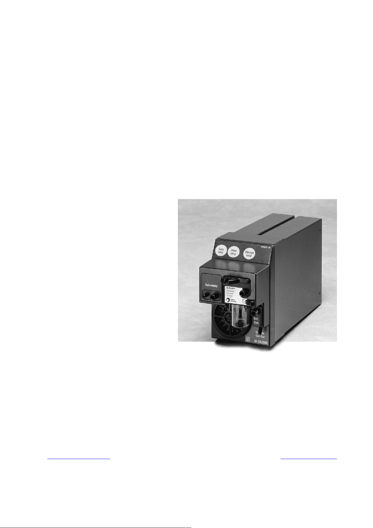
S/5TM Compact Airway Module, M-CAiOVX (rev. 01)
TM
S/5
S/5
S/5
Compact Airway Module, M-CAiOV (rev. 03)
TM
Compact Airway Module, M-CAiO (rev. 02)
TM
Compact Airway Module, M-COVX (rev. 02)
TM
S/5
S/5
Compact Airway Module, M-COV (rev. 03)
TM
Compact Airway Module, M-CO (rev. 02)
TM
S/5
Compact Airway Module, M-C (rev. 02)
Technical Reference Manual Slot
Datex-Ohmeda Inc.
3030 Ohmeda Drive
53707-7550 MADISON, WIS
USA
Tel. +1-608-221 1551, Fax +1-608-222 9147
www.us.datex-ohmeda.com
All specifications are subject to change without notice.
Document No. 800 1009-1
June 2001
Datex-Ohmeda Division,
Instrumentarium Corp.
P.O. Box 900, FIN-00031
DATEX-OHMEDA, FINLAND
Tel. +358 10 394 11 Fax +358 9 146 3310
www.datex-ohmeda.com
Instrumentarium Corp. All rights reserved.
Page 2

Page 3

Table of contents
TABLE OF CONTENTS
S/5 Compact Airway Modules
TABLE OF CONTENTS I
TABLE OF FIGURES III
INTRODUCTION 1
1 SPECIFICATIONS 2
1.1 General specifications ..............................................................................................................................2
1.2 Typical performance .................................................................................................................................2
1.2.1 CO
1.2.2 O
1.2.3 N
1.2.4 Respiration Rate (RR) .......................................................................................................................3
1.2.5 Anesthetic Agents (AA)......................................................................................................................3
1.2.6 MAC ................................................................................................................................................3
1.3 Gas specifications ....................................................................................................................................3
1.3.1 Normal conditions............................................................................................................................4
1.3.2 Conditions exceeding normal............................................................................................................4
1.4 Patient spirometry specifications...............................................................................................................5
1.4.1 Normal conditions............................................................................................................................5
1.4.2 Conditions exceeding normal............................................................................................................6
1.5 Gas exchange specifications .....................................................................................................................7
1.5.1 VO
1.5.2 RQ...................................................................................................................................................7
..................................................................................................................................................2
2
....................................................................................................................................................2
2
O .................................................................................................................................................2
2
and VCO2...................................................................................................................................7
2
2 FUNCTIONAL DESCRIPTION 8
2.1 Measurement principle .............................................................................................................................8
2.1.1 CO
2.1.2 O
, N2O, and agent measurement ...................................................................................................8
2
measurement ............................................................................................................................10
2
2.1.3 Patient spirometry ..........................................................................................................................10
2.1.4 Gas exchange measurement...........................................................................................................12
2.2 Main components...................................................................................................................................13
2.2.1 Gas sampling system......................................................................................................................13
2.2.2 TPX measuring unit.........................................................................................................................17
2.2.3 OM measuring unit .........................................................................................................................17
2.2.4 PVX measuring unit.........................................................................................................................18
2.2.5 Gas exchange ................................................................................................................................19
2.2.6 CPU board .....................................................................................................................................19
2.2.7 OM board.......................................................................................................................................20
2.2.8 PVX board ......................................................................................................................................20
2.3 Connectors and signals...........................................................................................................................21
3 SERVICE PROCEDURES 22
3.1 General service information.....................................................................................................................22
3.1.1 OM measuring unit .........................................................................................................................22
3.1.2 TPX measuring unit.........................................................................................................................22
3.1.3 OM, TPX, and PVX measuring unit....................................................................................................22
Document No. 800 1009-1
i
Page 4

Datex-Ohmeda S/5 monitors
3.1.4 Serviceable or exchangeable parts..................................................................................................22
3.2 Service check.........................................................................................................................................23
3.2.1 Recommended tools......................................................................................................................23
3.2.2 Recommended parts......................................................................................................................23
3.3 Disassembly and reassembly..................................................................................................................31
3.3.1 PVX unit.........................................................................................................................................31
3.3.2 Pump unit......................................................................................................................................31
3.3.3 CPU board .....................................................................................................................................31
3.3.4 Software of CPU board ...................................................................................................................32
3.3.5 Instructions after replacing software or CPU board ...........................................................................32
3.4 Adjustments and calibrations..................................................................................................................32
3.4.1 Gas sampling system adjustment ...................................................................................................32
3.4.2 Flow rate measurement..................................................................................................................32
3.4.3 Flow rate adjustment......................................................................................................................33
3.4.4 Gas calibration...............................................................................................................................33
3.4.5 Flow calibration..............................................................................................................................33
4 TROUBLESHOOTING 34
4.1 Troubleshooting charts ...........................................................................................................................34
4.1.1 CO
4.1.2 Patient spirometry..........................................................................................................................36
4.1.3 Gas exchange ................................................................................................................................38
4.2 Gas sampling system troubleshooting .....................................................................................................39
4.2.1 Sampling system leak test..............................................................................................................39
4.2.2 Steam test for the Nafion
4.3 OM measuring unit troubleshooting.........................................................................................................40
4.4 TPX measuring unit troubleshooting.........................................................................................................40
4.5 PVX measuring unit troubleshooting ........................................................................................................40
4.6 CPU board troubleshooting .....................................................................................................................40
4.7 Error messages.......................................................................................................................................41
measurement..........................................................................................................................35
2
TM
tubes....................................................................................................39
5SERVICE MENU 42
5.1 General menu ........................................................................................................................................43
5.2 Gases service menu ...............................................................................................................................44
5.3 Spirometry service menu ........................................................................................................................46
6 SPARE PARTS 48
6.1 Spare parts list.......................................................................................................................................48
6.1.1 M-C rev. 00, M-CO rev. 00, M-CAiO rev. 00, M-COV rev. 01, M-CAiOV rev. 01, M-COVX rev. 00 ..........48
6.1.2 M-CAiOVX rev. 00, M-CAiOV rev. 02, M-CAiO rev. 01, M-COVX rev. 01, M-COV rev. 02, M-CO rev. 01, M-
C rev. 01..................................................................................................................................................49
6.1.3 S/5 M-CAiOVX rev. 01, S/5 M-CAiOV rev. 03, S/5 M-CAiO rev. 02, S/5 M-COVX rev. 02, S/5 M-COV
rev. 03, S/5 M-CO rev. 02, S/5 M-C rev. 02 ..............................................................................................49
6.1.4 Front panel stickers........................................................................................................................49
6.1.5 S/5 stickers...................................................................................................................................50
6.1.6 Planned Maintenance (PM) Kits: .....................................................................................................51
7 EARLIER REVISIONS 52
APPENDIX A 53
SERVICE CHECK FORM A-1
ii
Document No. 800 1009-1
Page 5

Table of contents
TABLE OF FIGURES
Figure 1 TPX sensor principle..............................................................................................................................8
Figure 2 Absorbance of N
O and CO2..................................................................................................................9
2
Figure 3 Infrared absorbance of AAs ...................................................................................................................9
Figure 4 O
measurement principle ..................................................................................................................10
2
Figure 5 Absorber ............................................................................................................................................14
Figure 6 Gas sampling system layout, M-C........................................................................................................15
Figure 7 Gas sampling system layout, M-CAiOV, M-CAiOVX, M-CAiO, M-COVX, M-COV, M-CO..............................16
Figure 8 Gas tubing layout ...............................................................................................................................16
Figure 9 TPX measuring unit .............................................................................................................................17
Figure 10 OM measuring unit .........................................................................................................................18
Figure 11 PVX measuring unit.........................................................................................................................18
Figure 12 Signal processing...........................................................................................................................19
Figure 13 Control logic...................................................................................................................................20
Figure 14 Calibration data stored in EEPROM..................................................................................................20
Figure 15 Module bus connector pin layout ....................................................................................................21
Figure 16 Pneumatic unit and reference gas connection block.........................................................................25
Document No. 800 1009-1
iii
Page 6

Datex-Ohmeda S/5 monitors
iv
Document No. 800 1009-1
Page 7
INTRODUCTION
X
V
V
X
This section provides information for maintenance and service of the S/5 Compact Airway
modules. The Compact Airway modules are double width plug-in modules. M-C, M-CO, M-COV, MCOVX, M-CAiO, M-CAiOV, M-CAiOVX and M-CAiOVX/SERVICE are designed for use with the S/5
monitors. The modules provide airway and respiratory measurements.
Letters in the module name stand for:
M = plug-in module, C = CO
A = anesthetic agents, and i = agent identification
About M-CAiOVX/SERVICE module
The M-CAiOVX/SERVICE module is meant for service purposes only. It can be used as a loan
module if the module in the hospital should be sent to the factory for repair. The specifications that
apply to the M-CAiOVX apply also to the M-CAiOVX/SERVICE module. Module differences: the
colour of the front mask is green, the front panel has a “SERVICE” text and there are no front panel
keys equipped.
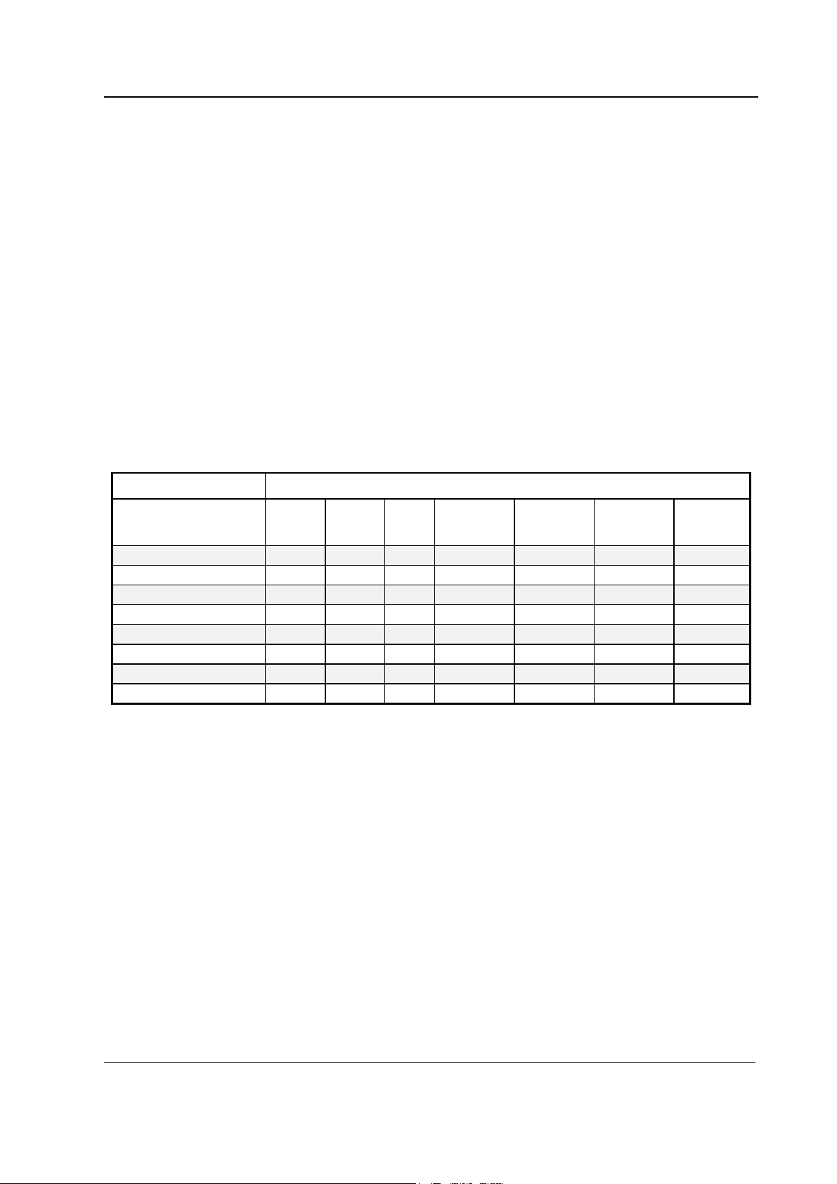
Table 1 Options for Compact Airway modules
Compact Airway modules
and N2O, O = patient O2, V = patient spirometry, X = gas exchange,
2
Modules Parameters/measurements
M-CAiOV
M-CAiO
M-CAiO
M-CO
M-COV
M-CO
M-C
M-CAiOVX/SERVICE
CO
2
• • • • • • •
••• • • •
• • • • •
••• •
• • • • •
•••
• •
••• • • • •
N2OO2Anesthetic
NOTE: Do not use identical modules in the same monitor simultaneously. The M-C, M-CO, M-COV,
M-COVX, M-CAiO, M-CAiOV, M-CAiOVX and M-CAiOVX/SERVICE are considered identical modules.
NOTE: The Compact Airway Module and Airway Module, G-XXXX, cannot be used simultaneously in
the same monitor.
NOTE: The Compact Airway modules cannot be used in the Extension Frame, F-EXT4.
NOTE: Anesthetic agents and N
O values are not displayed with Critical Care main software, but
2
when present in the module they are calculated for compensation of CO
agents
Agent ID Spirometry Gas
exchange
and O2.
2
1
Document No. 800 1009-1
Page 8

Datex-Ohmeda S/5 monitors
1 SPECIFICATIONS
1.1 General specifications
Module size, W × D × H 75 × 228 × 112 mm, 2.9 × 9.0 × 4.4 in
Module weight 1.6 kg/3.7 lbs
Operating temperature +10...+40 °C
Storage temperature -25...+70 °C
Atmospheric pressure 666...1060 hPa /
Humidity 10...95 % non-condensing (in airway 0...100 %, condensing)
Power consumption 12.6 W Prms, 14.6 W momentary
Protection against electrical shock
(67...106 kPa)
(500...800 mmHg)
(666...1060 mbar)
Type BF
1.2 Typical performance
1.2.1 CO
1.2.2 O
1.2.3 N2O
2
Measurement range 0...15 vol% (0...15 kPa, 0...113 mmHg)
Measurement rise time < 400 ms typical
Accuracy ±(0.2 vol% +2 % of reading)
Gas cross effects < 0.2 vol% (O
concentration is below 0.1%, 0.0% is displayed.
If CO
2
2
Measurement range 0 to 100 vol%
Measurement rise time < 400 ms typically
Accuracy ±(1 vol% +2% of reading)
Gas cross effects < 1 vol%; anesthetic agents
Fi-Et difference resolution 0.1 vol%
O
2
Measurement range 0 to 100 %; N2O
Measurement rise time < 450 ms typically
Accuracy ±(2 vol% +2% of reading)
Gas cross effects < 2 vol%; anesthetic agents
< 2 vol%; N
, N2O, anesthetic agents)
2
O
2
2
Document No. 800 1009-1
Page 9

1.2.4 Respiration Rate (RR)
Measurement range 4...60 breaths/min
Detection criteria 1 % variation in CO
1.2.5 Anesthetic Agents (AA)
Measuring range
Hal, Enf, Iso 0 to 6 vol%
Sev 0 to 8 vol%
Des 0 to 20 vol%
Measurement rise time < 400 ms typically
Accuracy ±(0.15 vol% +5% of reading)
Gas cross effects < 0.15 vol% N
Resolution is two digits when the AA concentration is below 1.0 vol%.
If AA concentration is below 0.1 vol%, 0.0% is displayed.
Identification threshold 0.15 vol% typically
Identification time < 20 s (for pure agents)
Compact Airway modules
2
O
2
Mixture identification threshold for 2. agent:
1.2.6 MAC
Range 0...9.9 MAC
Equation:
%(ETAA)
=MAC(AA)
x(AA)
where x(AA): Hal=0.75 %, Enf=1.7 %, Iso=1.15 %, Sev=2.05 %, Des=6.0 %.
1.3 Gas specifications
Airway humidity 0...100 %, condensing
Sampling rate 200 ±20 ml/min. (sampling line 2-3 m, normal conditions)
Sampling delay 2.5 seconds typical with a 3 m sampling line
Total system response time 2.9 seconds typical with a 3 m sampling line, including sampling
Display update rate breath-by-breath
Automatic compensation for pressure, CO
0.2 vol% +10% of total conc.
OETN
+
2%
Formula 1
100
delay and rise time
O and CO2-O2 collision broadening effect.
2-N2
Warm up time 2 min. for operation with CO
, O2, and N2O
2
5 min. for operation of anesthetic agents
30 min. for full specifications
Autozeroing interval Immediately after ‘calibrating gas sensor’ and 2, 5, 10, 15, 30, 45,
60 minutes after start-up, then every 60 minutes
Document No. 800 1009-1
3
Page 10

Datex-Ohmeda S/5 monitors
1.3.1 Normal conditions
Accuracy specifications apply in normal conditions (after 30 minutes warm-up period):
Ambient temperature 18...28 °C, within ±5 °C of calibration
Ambient pressure 500...800 mmHg, ±50 mmHg of cal.
Ambient humidity 20...80 % RH, ±20 % RH of cal.
Non-disturbing gases
− Ethanol C
− Acetone (< 0.1%)
− Methane CH
− Nitrogen N
− Carbon monoxide CO
− Nitric Oxide NO (< 200 ppm)
− water vapor
Maximum effect on readings
− CO
− O
− anesthetic agents < 0.15 vol%
Effect of Helium decreases CO
OH(< 0.3%)
2H5
(< 0.2%)
4
2
< 0.2 vol%
2
, N2O < 2 vol%
2
readings < 0.6 vol% typically
2
1.3.2 Conditions exceeding normal
Accuracy specifications under the following conditions; :
Ambient temperature 10...40 °C, within ±5 °C of calibration
Ambient pressure 500...800 mmHg, ±50 mmHg of calibration
Ambient humidity 10...98 % RH, ±20 % RH of calibration
During warm-up 2 to 10 minutes (anesthetic agents 5-10 minutes), under normal conditions
During warm-up 10 to 30 minutes, under normal conditions
CO
2
O
2
N2O
Agents: Hal, Enf, Iso,
Sev, Des
Accuracy under different conditions (see above)
Condition and Condition
±(0.3 vol% + 4 % of reading)
(at 5 vol% error ±0.5 vol%)
±(0.4 vol% + 7 % of reading)
(at 5 vol% error ±0.75 vol%)
±(2 vol% + 2% of reading) ±(3 vol% + 3% of reading)
±(3 vol% + 3% of reading) ±(3 vol% + 5% of reading)
±(0.2 vol% + 10% of reading) ±(0.3 vol% + 10% of reading)
4
Document No. 800 1009-1
Page 11

1.4 Patient spirometry specifications
1.4.1 Normal conditions
Accuracy specifications apply in normal conditions (after 10 minutes warm-up period):
Ambient temperature 10...40 °C
Ambient pressure 500...800 mmHg
Ambient humidity 10...98 %RH
Airway humidity 10...100 %RH
Respiration rate 4...35 breaths/min (adults)
4...50 breaths/min (pediatric)
I:E ratio 1:4.5...2:1
Intubation tube 5.5...10 mm (adults), 3...6 mm (pediatric)
Compact Airway modules
Airway pressures (Paw, P
Measurement range -20...+100 cmH2O
Resolution 0.5 cmH
Accuracy ±1 cmH
Airway flow
Measurement range 1.5...100 l/min (adults)
(for both directions) 0.25...25 l/min (pediatric)
Tidal volume
Measurement range 150...2000 ml (adults), 15...300 ml (pediatric)
Resolution 1 ml
Accuracy ±6 % or 30 ml (adult), ±6 % or 4 ml (pediatric)
Minute volume
Measurement range 2...20 l/min (adults), 0.5...5 l/min (pediatric)
Resolution 0.1 l/min
peak
, P
, PEEPe, PEEP
plat
iStat
O
2
O
2
, PEEP
iDyn
, P
mean
)
Compliance
Measurement range 4...100 ml/cmH2O (adult), 1...100 ml/cmH2O (pediatric)
Resolution 1 ml/cmH
Airway resistance
Measurement range 0...40 cmH2O/ l/s
Resolution 1 cmH
O (adult), 0.1 ml/cmH2O (pediatric)
2
O/ l/s
2
5
Document No. 800 1009-1
Page 12

Datex-Ohmeda S/5 monitors
Other parameters
Specifications apply in conditions listed in patient spirometry specifications.
Dead space of the sensor
9.5 ml (adult), 2.5 ml (pediatric)
Resistance of the sensor
0.5 cmH2O @ 30 l/min (adult), 1.0 cmH2O @ 10 l/min (pediatric)
1.4.2 Conditions exceeding normal
Accuracy specifications under the following condition (during warm-up 2 to 10 minutes):
Airway Pressure(Paw)
Accuracy ±2 cmH2O
Tidal volume
Accuracy ±10 % or 100 ml (adult), ±10 % or 10 ml (pediatric)
6
Document No. 800 1009-1
Page 13

1.5 Gas exchange specifications
Mathemathical integration of airway flow and gas concentration for intubated, mechanically
ventilated and/or partly spontaneously breathing patients.
NOTE: These specifications apply only when a 2 meter gas sampling line is used, and a Y-piece
with a physical dead space less than 8 ml.
Compact Airway modules
NOTE: These specifications only apply if the FiO
0.2 % during the inspiratory cycle at the measurement point.
1.5.1 VO2 and VCO
Measurement range 50...1000 ml/min
Resolution 10 ml/min
Accuracy ±10 % or 10 ml; when FiO
1.5.2 RQ
Measurement range 0.6...1.2
Resolution 0.05
level delivered to the patient is varing by less than
2
2
< 65 %
2
±15 % or 15 ml; when 65 % < FiO
< 85 %
2
Document No. 800 1009-1
7
Page 14
Datex-Ohmeda S/5 monitors
2 FUNCTIONAL DESCRIPTION
2.1 Measurement principle
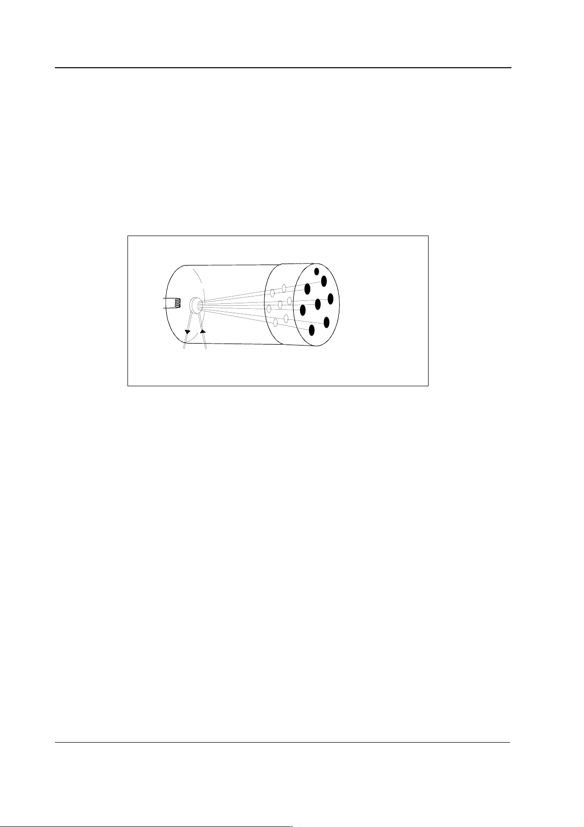
2.1.1 CO2, N2O, and agent measurement
TPX is a side stream gas analyzer, measuring real time concentrations of CO2, N2O and anesthetic
agents (Halothane, Enflurane, Isoflurane, Desflurane, and Sevoflurane).
Sample
chamber
Temp sensor
Thermopile
detectors
Sample
gas out
Figure 1 TPX sensor principle
Anesthetic agents or mixtures of two anesthetic agents are automatically identified and
concentrations of the identified agents are measured. TPX also detects mixtures of more than two
agents and issues an alarm.
TPX is a nondispersive infrared analyzer, measuring absorption of the gas sample at seven infrared
wavelengths, which are selected using optical narrow band filters.
The infrared radiation detectors are thermopiles.
Concentrations of CO
Sample
gas in
and N2O are calculated from absorption measured at 3-5 µm.
2
8
Document No. 800 1009-1
Page 15

Compact Airway modules
Figure 2 Absorbance of N2O and CO
2
Identification of anesthetic agents and calculation of their concentrations is performed by
measuring absorptions at five wavelengths in the 8-9 µm band and solving the concentrations
from a set of five equations.
Figure 3 Infrared absorbance of AAs
The measuring accuracy is achieved utilizing numerous software compensations. The
compensation parameters are determined individually for each TPX during the factory calibration.
Document No. 800 1009-1
9
Page 16
Datex-Ohmeda S/5 monitors
2.1.2 O2 measurement
The differential oxygen measuring unit uses the paramagnetic principle in a pneumatic bridge
configuration. The signal picked up with a differential pressure transducer is generated in a
measuring cell with a strong magnetic field that is switched on and off at a frequency of 165 Hz.
The output signal is a DC voltage proportional to the O
gases to be measured.
Sample in
Microphone
Electromagnet
concentration difference between the two
2
Mixture
out
Switched
magnetic
field
Figure 4 O2 measurement principle
2.1.3 Patient spirometry
In mechanical ventilation breaths are delivered to the patient by a ventilator with a proper tidal
volume (TV), respiration rate (RR), and inspiration / expiration ratio in time (I:E) determined by the
settings of the ventilator.
The Patient Spirometry monitors patient ventilation. The following parameters are displayed:
− Expiratory and inspiratory tidal volume (TV) in ml
− Expiratory and inspiratory minute volume (MV) in l/min
− Expiratory spontaneous minute volume in l/min
− Inspiration/expiration ratio (I:E)
Airway pressure
− Peak pressure (P
− Mean airway pressure (P
monitors
− End inspiratory pressure (P
− PEEPi, PEEPe; available only in S/5 Critical Care and Compact Critical Care monitors
− Total positive end expiratory pressure (PEEP
Compact Anesthesia monitors
− Real time airway pressure waveform (P
− Static Positive end expiratory pressures (Static PEEP
S/5 Critical Care and Compact Critical Care monitors
Reference in
)
peak
); available only in S/5 Critical Care and Compact Critical Care
mean
)
plat
); available only in S/5 Anesthesia and
tot
)
aw
and Static PEEPe); available only in
i
10
Document No. 800 1009-1
Page 17

Compact Airway modules
− Static Plateau pressure (Static Pplat); available only in S/5 Critical Care and Compact
Critical Care monitors
− Static Compliance (Static Compl); available only in S/5 Critical Care and Compact Critical
Care monitors
Airway flow
PEEP, P
peak
, P
mean
, and P
are measured by pressure transducer on the PVX board. Atmospheric
plat
pressure is used as a reference in measurement. The pressure measurement is made from the
airway part that is closest to the patient between patient circuit and intubation tube.
=intrinsic PEEP, PEEP
PEEP
i
-PEEP
tot
e
Static pressure measurement maneuvres are automatically identified based on a increased zero
flow period at the end of the inspiration or expiration.
Static Compliance is calculated if Static PEEP and Static P
measurements were done within a 2
plat
minutes period.
− Real time flow waveform (V')
− Compliance (Compl)
− Airway resistance (Raw)
− Pressure volume loop
− Flow volume loop
The measurement is based on measuring the kinetic gas pressure and is performed using the Pitot
effect. A pressure transducer is used to measure the Pitot pressure. The obtained pressure signal is
linearized and corrected according to the density of the gas. Speed of the flow is calculated from
these pressure values and TV value is then integrated. MV value is further calculated and averaged
using TV and RR (respiratory rate) values.
Compliance and airway resistance
Compliance is calculated for each breath from the equation
TV
Compl−−=
plat
exp
ei
PEEPPEEPP
Formula 2
Compliance tells how big a pressure difference is needed to deliver a certain amount of gas into
the patient.
The airway resistance, Raw, is calculated using an equation, that describes the kinetics of the gas
flow between the lungs and the D-lite. The equation states that the pressure at the D-lite can at any
moment of the breath be approximated using the equation
tVtVRaw
)()('
tp
=
)(
+×
++
ie PEEPPEEPCompl
Formula 3
where p(t), V’(t) and V(t) are the pressure, flow and volume measured at the D-lite at a time t, Raw is
the airway resistance, Compl is the compliance and PEEP
expiratory pressure (PEEP
).
tot
+PEEPi is the total positive end
e
11
Document No. 800 1009-1
Page 18

Datex-Ohmeda S/5 monitors
TM
D-lite
Patient Spirometry uses a specific sensor called D-liteTM flow sensor. Different types of the D-lite
sensors are available: adult sensor for measuring adults and pediatric sensor for children. Both are
available as reusable versions and D-lite sensor also for single use.
D-lite adapter is designed to measure kinetic pressure by two-sided Pitot tube. Velocity is
calculated from pressure difference according to Bernoulli's equation. Flow is then determined
using the calculated velocity.
v=
2dP×
(from Bernoulli's equation) Formula 4
ρ
F=v A× ,
where:
F = flow (l/min), v = velocity (m/s), A = cross area (m
ρ
= density (kg/m3)
Finally the volume information is obtained by integrating the flow signal.
2.1.4 Gas exchange measurement
The gas exchange measurement uses the D-liteTM flow sensor and the gas sampler.
The basic data which is needed to obtain O
concentrations.
Concentrations have been corrected for delay and deformation during the transport of the gas
sample in a sidestream gas measurement sensor.
To obtain the amount of O
the amount that is inhaled.
2
), dP = pressure difference (cmH2O),
consumption and CO2 production are volumes and
2
consumed in ml/min, the amount which is exhaled is subtracted from
2
To obtain the amount of CO
the amount that is exhaled.
These amounts can be obtained by multiplying each measured volume piece (dv) by the
corresponding gas concentration:
and
Using inspiratory and expiratory minute volumes MV
concentrations fi and fe these equations can be rewritten as:
12
Document No. 800 1009-1
producted in ml/min, the amount which is inhaled is subtracted from
2
−
dvfdvf OO
VO
=2
ò
insp
VCO 22 Formula 6
=2
ò
exp
22
ò
dvfdvf COCOò−
inspexp
and MVe and volume-weighted inspiratory
i
eOiO=2 MVfe-MVfiVO 22 ×× [ml/min] Formula 7
Formula 5
Page 19

Compact Airway modules
iCOeCO=2 MVfi-MVfeVCO 22 ×× [ml/min] Formula 8
To obtain results which are less sensitive to errors in volume measurements, so-called Haldane
transformation is used. This means taking advantage of the fact that the patient is not consuming
nor producing nitrogen: the amount of nitrogen inhaled is equal to the amount
exhaled fi
and VCO2 can then be written as:
VO
2
× MVi=feN2×MVe.
N2
iOHaldO2 )MVfef-(fi=VO 22 × [ml/min] Formula 9
iCOCOHald2 )MVfi-fe(f=VCO 22× [ml/min] Formula 10
with
f
Hald
= (1-fi
– fiO2 – fi
CO2
N2O
- fi
Ane1
– fi
Ane2
) / (1-fe
– feO2 – fe
CO2
N2O
- fe
Ane1
– fe
Ane2
)
EE=(5.5 × VCO
2
with Un=Urea Nitrogen Excretion = 13 g/day (for adults only).
2.2 Main components
The compact airway modules consist of:
• Gas sampling system
• TPX measuring unit
• OM measuring unit
• PVX measuring unit
• CPU board
• OM board
• PVX board
2.2.1 Gas sampling system
The sampling system takes care of drawing a gas sample to the analyzers at a fixed rate.
The gas sampling system samples the measured air to the module, and removes water and
impurities from it. A sampling line is connected to the water trap. The pump draws gas through the
sampling line to gas measuring units. After the measurements, the gas is exhausted from sample
gas out connector.
) + (1.76 × VO2) + (1.99 × Un) [kcal/day] Formula 11
The M-COVX and M-CAiOVX modules have a different gas sampling system compared to the other
modules. A number of flow restrictors have been changed to create a bigger pressure difference
with ambient pressure in the gas sensors. The sample flow is however about the same (200
ml/min).
A bigger pressure difference makes the deformations of the gas concentration curves less sensitive
to high variations of the airway pressures thus meeting also the accuracy requirements of gas
exchange for these applications.
13
Document No. 800 1009-1
Page 20

Datex-Ohmeda S/5 monitors
D-fend
TM
The sample is drawn through a sampling line. Then gas enters the monitor through the water trap,
where it is divided into two flows, a main flow and a side flow. The main flow goes into the
analyzers. This flow is separated from the patient side by a hydrophobic filter. The side flow creates
a slight subatmospheric pressure within the D-fend water trap which causes fluid removed by the
hydrophobic filter to collect in the bottle.
Zero valve and absorber
Figure 5 Absorber
NafionTM tubes
1)
A nafion tube is used between the water trap and the zero valve to balance the sample gas
humidity with that of ambient air. The tube will prevent errors caused by the effect of water vapor on
gas partial pressure when humid gases are measured after calibration with dry gases. Another
nafion tube is used between the absorper and the pneumatic unit to prevent humidity caused by
absorb of CO
The main flow passes through a magnetic valve before
proceeding to the analyzers. This valve is activated to establish
the zero points for the TPX and OM units. When the valve is
activated, room air is drawn through the absorber into the internal
system and the gas sensors. Paralyme is used as an absorbent.
.
2
Gas analyzers
After the zero valve and nafion tube the gas passes through TPX and OM units. The oxygen sensor
has two inputs. One input accepts the main flow and the other draws in room air for reference. Both
gas flows exit from a single port.
Sample flow differential pressure transducer
The sample flow differential pressure transducer measures pressure drop across OM inlet restrictor
and calculates sample flow from the pressure difference.
Working pressure transducer
The working pressure transducer measures absolute working pressure between the TPX unit and
OM unit. It is used for messages: ‘sample line blocked’, ‘check D-fend’, ‘replace D-fend’ and
‘check sample gas outlet’.
1)
Nafion is a trademark of Perma Pure Inc.
14
Document No. 800 1009-1
Page 21

Pneumatic unit
The pneumatic unit contains zeroing valve, occlusion valve and tubing connections. There is a
series of restrictors and chambers forming a pneumatic filter to prevent pressure oscillations from
the pump to reach the measuring units. The occlusion valve connection to room air includes a dust
filter and the zero valve connection to room air includes an absorber.
Connection block
The connection block contains sample gas outlet connector and OM unit reference gas inlet. The
inlet is equipped with a dust filter.
Occlusion valve
The valve is activated when the sampling line gets occluded. The main flow is then diverted to the
side flow of the D-fend water trap to faster remove the occlusion.
Sampling pump and damping chamber
Compact Airway modules
The gas sampling pump is a membrane pump that is run by a brushless DC-motor. Sample flow is
measured with a differential pressure transducer across a known restriction. The motor is
automatically controlled to maintain a constant flow, even when the D-fend water trap ages and
starts to get occluded. It also enables use of sample tubes with varying lengths and diameters.
The damping chamber is used to even out the pulsating flow and silence the exhaust flow.
NOTE: In no occasion is the flow reversed towards patient.
CO2 absorber
Nafion tube
Pneumatic unit
G
F
E
D
C
B
A
Pressure transducers
B1
B2
D-fend
Water trap
Nafion tube
Connection block
OUT
IN
Damping champer
Sampling pump
OUT
Figure 6 Gas sampling system layout, M-C
TPX unit
IN
15
Document No. 800 1009-1
Page 22

Datex-Ohmeda S/5 monitors
Nafion tube
CO2 absorber
Pneumatic unit
G
F
E
D
C
B
A
Pressure transducers
P
OUT
OM unit
REF
IN
D-fend
Water trap
Nafion tube
B1
B2
OUT
IN
Damping champer
Sampling pump
TPX unit
IN
OUT
Connection block
Figure 7 Gas sampling system layout, M-CAiOV, M-CAiOVX, M-CAiO, M-COVX, M-COV,
M-CO
Front panel
Sample
line
Filter
Zero
valve
D-fend
D-fend
1)
Absorber
Reference gas
Room air
1)
TPX
Pressure
transducer
p
Pressure
transducer
p
dp
OM
1)
Tubing marked with 1) is thinner in M-CAiOVX and M-COVX module.
Figure 8 Gas tubing layout
Room air
Filter
Occlusion
valve
Pump
16
Document No. 800 1009-1
Page 23

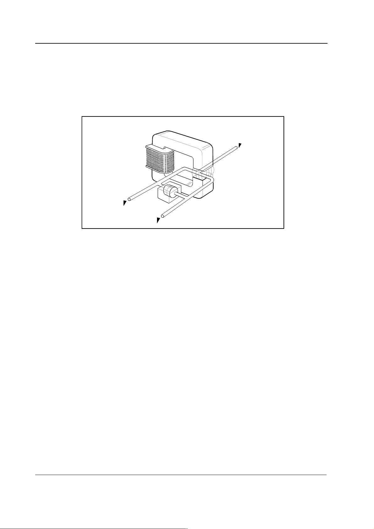
2.2.2 TPX measuring unit
The TPX unit is a non dispersive infrared analyzer, measuring absorption of the gas sample at seven
infrared wavelengths, which are selected using optical narrow band filters. The IR lamp is a 4 W
filament, surrounded by thermal isolation. There is a hole in the isolation, passing the radiation to a
conical measuring chamber with 4 mm length.
From the sample chamber, radiation goes into seven tubular light guides with reflective inner
surface. At the other end of each light guide, there is a thermopile detector with an optical filter in
front of it.
The Temp sensor measures TPX units’ temperature and it is used for temparature compensation.
The TPX unit includes TPX board located at the end of the unit. Its function is to connect the 7
thermopile signals and the temperature sensor signal to the CPU board.
Compact Airway modules
Figure 9 TPX measuring unit
2.2.3 OM measuring unit
The oxygen measurement is based on paramagnetic susceptibility. The gas and the reference gas,
which usually is room air, are conducted into a gap in an electromagnet with a strong magnetic
field switched on and off at a frequency of approximately 165 Hz.
An alternating differential pressure is generated between the sample and reference inputs due to
forces acting to the oxygen molecules in a magnetic field gradient.
The pressure is measured with a sensitive differential transducer, rectified with a synchronous
detector and amplified to produce a DC voltage proportional to the oxygen partial pressure
difference of the two gases.
17
Document No. 800 1009-1
Page 24

Datex-Ohmeda S/5 monitors
Figure 10 OM measuring unit
2.2.4 PVX measuring unit
NOTE: Never apply overpressure or negative pressure of more than 300 cmH2O to the flow and
volume tubing. Differential pressure max 25 cmH2O on one port at a time e.g. when connecting
tubes.
When Patient Spirometry is used, a special sensor, D-lite, replaces the normal airway adapter in
the patient circuit. A double lumen tubing is attached to the two connectors on the adapter and on
the module front panel.
The Patient Spirometry provides patient respiration monitoring capabilities using the D-lite and
Pedi-lite flow sensors.
Figure 11 PVX measuring unit
The measurement is based on measuring the kinetic gas pressure and is performed using the Pitot
effect. A pressure transducer is used to measure the Pitot pressure. The signal is then linearized
and corrected according to the density of the gas. Speed of the flow is calculated from the pressure
and TV is integrated from it.
The Patient Spirometry consists of airway connections, two pressure transducers, valves and
preamplifiers. The preamplifiers are connected to the A/D-converter on module main CPU.
The breathing flow of a patient passing through the D-lite adapter creates a pressure difference.
This pressure difference is measured by pressure transducer, B1. Overpressure and negative
pressure in airways are measured by another pressure transducer B2.
18
Document No. 800 1009-1
Page 25

Compact Airway modules
2.2.5 Gas exchange
The gas exchange measurement uses the concentrations measured by the TPX measurement unit
and the O
measurement unit, in combination with the flow from the PVX measurement unit. The
2
gas exchange calculation is done by software.
CAUTION The gas exchange measurement in the M-CAiOVX and M-COVX modules works
accurately only with 2 meter gas sampling lines.
2.2.6 CPU board
The CPU board contains the processor and memories and A/D-converters that are common to the
whole module. The CPU board also contains preamplifiers of TPX-sensor and drivers for valves, fan,
pump and lamp. The module is connected to the module bus through a RS-485 serial channel.
CPU boardTPX board
IR Thermopile Sensors
preamps
x 5
Anes.
Agents
N2O
CO
2
T Sensor
OM Board
MUX
Spirometry keyboard
PVX Board
T Sensor
O
2
Flow Press
Figure 12 Signal processing
x 2
MUX
and
buffer
MUX
and
buffer
2 ch
A / D
16 bit
RS-485
driver
CPU
80C196NT
Module Bus
19
Document No. 800 1009-1
Page 26

Datex-Ohmeda S/5 monitors
Lamp Unit
TPX
Lamp
Gas press
Diff press
MUX
OM Board
PVX
valves
Figure 13 Control logic
TPX Board
CPU Board
Lamp
Current
Sensing
MUX &
buffer
Temp
sensor
A / D
A / D
CPU Board
Valves
Valves
CPU
80C196NT
pneumatics
unit
Fan
Module Bus
reset
data
Figure 14 Calibration data stored in EEPROM
2.2.7 OM board
The Oxygen board contains the specific electronics for the oxygen sensor. Sample flow
measurement and sampling system pressure sensors are on this board. It also contains EEPROM’s
that store calibration data of both TPX and OM-sensors. The spirometry keyboard connection is on
this board.
EEPROM
OM Board
EEPROM
EEPROM
PVX Board
Factory calibration
data for OM and TPX
Factory calibration
data for PVX
EEPROM
Correction data for
amplification and
offset of all amplification
channels
CPU
80C196NT
RS-485
driver
Module Bus
2.2.8 PVX board
The Spirometry board is connected to the oxygen board. It contains pressure sensors for airway
pressure and flow measurement differential pressure and preamplifiers for those. Calibration data
of spirometry is stored on it’s own EEPROM.
20
Document No. 800 1009-1
Page 27

2.3 Connectors and signals
Compact Airway modules
13
25
1
14
Figure 15 Module bus connector pin layout
Table 2 Module bus connector pin description
Pin No I/O Signal
1 I RESET RS485
2 I -15 VDC
3 I +15 VDIRTY
4 I +15VDC
5 I/O -DATA RS485
6 I/O DATA RS485
7 Ground and Shield
8 I -RESET RS485
9n/c
10 n/c
11 n/c
12 n/c
13 Ground and Shield
14 I +24/+32 VDIRTY depends on power supply (not used)
15 I Ground DIRTY
16 n/c
17 n/c
18 n/c
19 n/c
20 I GASFR (not used)
21 I CTSD (not used)
22 I TXDD (not used)
23 O RXDD (not used)
24 I +5 VDC
25 I +5 VDC DIRTY, for infrared lamps
21
Document No. 800 1009-1
Page 28

Datex-Ohmeda S/5 monitors
3 SERVICE PROCEDURES
3.1 General service information
Field service of the compact airway modules is limited to replacing faulty circuit boards or
mechanical parts. The circuit boards should be returned to Datex-Ohmeda for repair.
Datex-Ohmeda is always available for service advice. Please provide the unit serial number, full
type designation and a detailed fault description.
CAUTION Only trained personnel with appropriate equipment should perform the tests and
repairs outlined in this section. Unauthorized service may void warranty of the unit.
CAUTION The module electronics can only be repaired and calibrated at the factory.
3.1.1 OM measuring unit
CAUTION Due to the complicated and sensitive mechanical construction any service inside
the O
measuring unit should not be attempted.
2
3.1.2 TPX measuring unit
CAUTION The TPX photometer and its components are repaired/calibrated at the factory.
Attempts to repair/calibrate the unit elsewhere will adversely affect operation of the
unit. The information provided is for reference only.
3.1.3 OM, TPX, and PVX measuring unit
CAUTION The OM, TPX, and PVX measuring units can be repaired only at the factory.
3.1.4 Serviceable or exchangeable parts
• Absorber
• D-fend
• Nafion tubes
• Fan filter
• Fan
• CPU board
• CPU software
• PVX Unit including PVX board
• Pump
NOTE: After any component replacement see chapter Adjustments and calibrations.
22
Document No. 800 1009-1
Page 29

3.2 Service check
These instructions include complete procedures for a service check. The service check is
recommended to be performed after any service repair. However, the service check procedures can
also be used for determining possible failures.
The procedures should be performed in ascending order.
The instructions include a check form, Appendix A, which should be filled in when performing the
procedures.
Compact Airway modules
The mark
the procedure.
The procedures are designed for monitors with software of level 00.
? in the instructions means that the check form should be signed after performing
3.2.1 Recommended tools
Tool Order No. Notes
Screwdriver
Ambient pressure manometer
Flowmeter
Flow cassette 50/1.1 873812
Extra silicon tubing
Calibration gas and the regulator 755583 (gas)
755533
Calibration gas and the regulator 755587 (gas)
755530
Calibration gas and the regulator 755581 (gas)
755533
for M-CAiOVX/M-CAiOV/M-CAiO
for M-COVX
for M-COV/M-CO/M-C
Gas Interface Cable 2.5 m / 8 ft 884299
3.2.2 Recommended parts
Part Order No. Notes
Absorber 895933
D-fend 876446
D-fend+ 881319 for M-COVX
Sampling line 3 m/10 ft 73319 anesthesia gas sampling line
Sampling line 2 m/7 ft 73318 for M-CAiOVX/M-COVX
D-lite / Pedi-lite 733950/73393
D-lite+ for condensing active humidification circuits
Document No. 800 1009-1
23
Page 30

Datex-Ohmeda S/5 monitors
Part Order No. Notes
Spirometry tube 2 m 890031
Spirometry tube 3 m 884101
D-fend O-ring (2 pcs) 65312
Filter (3 pcs) 886136 1 pcs @ latest revisions
Filter assembly 896025 @ latest revisions
Nafion tubes (2 pcs) 733382
Fan filter 886236
All modules
Detach the module box by removing the two screws from the back of the module. Be careful with
loose latch and spring pin for locking.
1. Check internal parts:
− all screws are tightened properly
− all cables are connected properly
− tubes are not pinched and there are no sharp bends on them
− all tubes are connected properly
− the front cover grounding pins are not bent against the CPU board
− there are no loose objects inside the module
NOTE: The tubes that are connected to the Oxygen board pressure transducers should not
be pressed too deep.
NOTE: Make sure that tubes are not in contact with the sampling pump or the O
its springs.
sensor, or
2
2. Check external parts:
?
3. Clean or replace the fan filter.
?
4. Detach the D-fend. Check the condition of the rubber O-rings on the metal D-fend
24
Document No. 800 1009-1
?
− the front cover and the front panel stickers are intact
− all connectors are intact and are attached properly
− the D-fend latch is moving properly
− the module box, the latch and the spring pin are intact
connectors, located in the Compact Airway Module front cover.
If necessary, detach the connectors by first disconnecting the tubes, then removing the
locking rings from the back of the front cover.
NOTE: The O-rings are recommended to be replaced annually.
?
Page 31

Compact Airway modules
5. Check that flow of air through the filters in the reference gas connection block (1 pc) and in
the pneumatic unit (2 pcs) is not obstructed.
Z
e
r
o
f
i
l
t
e
r
F
E
D
O
c
c
l
u
s
i
o
n
f
i
l
t
e
C
r
B
A
Reference gas
connection block
Figure 16 Pneumatic unit and reference gas connection block
NOTE: The filters are recommended to be replaced annually.
?
• Replace the D-fend and sampling line by new.
NOTE: Use only Datex-Ohmeda sampling lines in order to ensure proper functioning. 2
m/7 ft sampling line should be used with M-COVX and M-CAiOVX.
• Connect the Compact Airway Module to the Central Unit’s Module motherboard
using the Gas interface cable (the grounding plates of the cable should be removed).
• Turn the monitor on.
• Configure the monitor screen so that all the needed parameters are shown, for
example as follows:
Monitor Setup - Screen 1 Setup - Waveform fields - Field 1 - Paw
Field 2 - Flow
Field 3 - Off
Field 4 - O2
Field 5 - AA
Field 6 - CO2
Digit Fields
Lower Field 1 - Gases
• Preset the following gas measurement settings (if available):
Airway Gas - Select Agent - Hal
Spirometry Setup - Scaling Vol
Paw Scale - 20
Flow Scale - 15
6. Check that the fan is running.
?
25
Document No. 800 1009-1
Page 32

Datex-Ohmeda S/5 monitors
7. Wait until the message ‘Calibrating gas sensor’ disappears from the screen, then enter the
Service menu.
Monitor Setup - Install/Service (password 16-4-34) - Service (password 26-23-8)
Take down the information regarding Compact Airway Module software.
?
8. Enter the Compact Airway Module service menu.
Parameters - Gas Unit - General
Check that the shown module configuration corresponds with the used Compact Airway
Module type.
?
9. Check that the ‘Timeouts’, ‘Bad checksums’ and ‘Bad c-s by mod’ -values are not increasing
faster than by 50 per second.
If one of the values is increasing faster it indicates a failure in module bus communication.
?
10. Enter the service menu Gases:
Gas Unit - Gases
Check that the flow measurement offset, i.e. the shown sample ‘Zero’ -value is within ±10
ml/min.
?
11. Check that the shown ‘Ambient’ -value corresponds with the current ambient pressure (±20
mmHg).
?
12. Check the zero valve.
Feed calibration gas and check that the gas readings in the service menu correspond with
the values on the gas bottle sticker. Keep feeding gas, then activate the zero valve from the
menu. The CO
(N2O, AA) reading should drop back near 0 %, the O2 reading near 21 %.
2
?
13. Perform the steam test for the Nafion tubes, or replace those by new. Replace the
absorber, if necessary.
CO
2
26
Document No. 800 1009-1
NOTE: The Nafion tubes are recommended to be replaced annually. In case of exchanging
the absorber it is recommended to replaced also this nafion tube.
NOTE: The CO
absorber is recommended to be replaced once in four years.
2
?
Page 33

Compact Airway modules
14. Perform sampling system leak test.
Prevent the module from performing the normal occlusion functions, i.e. controlling the
valves, by turning the pump first off, then on again from the menu.
Block the reference gas connector at the front panel.
Connect a flow cassette with high flow resistance value (50/1.1) to the end of the sampling
line and start following the ‘Amb-Work’ -value in the service menu. When the value exceeds
170 mmHg connect the other port of the flow cassette to the sample gas out connector and
switch the pump off.
Wait until pressure inside the sampling system is stabilized then notice the shown ‘AmbWork’ -value. The value, i.e. the pressure inside the sampling system should not drop more
than 6 mmHg in one minute.
If the pressure drops more, first ensure the made connections and repeat the test.
?
15. Check the flow rates.
Wait until the ‘Sample Flow’ -value is back near 200 ml /min.
Connect a flowmeter to the 3 meter sampling line (use a 2 meter sampling line for MCAiOVX and M-COVX) and check that the flow (the flowmeter reading) is within the following
range:
Sampling flow (ml/min) 180...220
If necessary, readjust the sampling flow:
Select ‘Sample gain adj’ from the menu. To increase the sampling flow, turn the ComWheel
counterclockwise, to decrease the flow, turn the ComWheel clockwise.
A change of 0.050 in the ‘Gain’ -value changes the flow approximately 10 ml/min.
After you have changed the gain, wait until the ‘Sample Flow’ -value on the screen gets back
near the original then check the flowmeter reading again.
Connect the flowmeter to the reference gas connector, check that the flow is within the
following range:
Reference flow
(ml/min)
M-CAiOVX/
M-COVX
27...40 25...45 31...45
M-C Others
Activate the zero valve on from the service menu. The ‘Sample Flow’ -value should not
change more than 20 ml/min. If the absorber is connected the value is 30 ml/min.
?
Document No. 800 1009-1
27
Page 34

Datex-Ohmeda S/5 monitors
16. Check that the ‘Amb-Work’ -value in the service menu is within the following range:
Amb-Work (mmHg) M-CAiOVX/M-COVX Others
?
17. Perform the gas calibration.
Airway Gas - Gas Calibration
NOTE: The calibration is not recommended to be performed before 30 minutes warm-up time.
Use calibration gas 755587 (5 % CO
and calibration gas 755583 (2 % Desflurane, 5 % CO
M-CAiOVX/M-CAiOV/M-CAiO,
and calibration gas 755581 (5 % CO
M-COV/M-CO/M-C.
70...115 40...75
, 95 % O2) for calibrating Airway Module, M-COVX,
2
, 33 % N2O, 55 % O2, balance N2) for
2
, 40 % N2O, 55 % O2) for calibrating
2
NOTE: You can calibrate the modules M-CO and M-COV also with the same calibration gas as
the M-COVX module, but M-C must always be calibrated with the gas 755581.
NOTE: For correct measurement values, modules need different amounts of oxygen in the
calibration. If you do not use the recommended calibration gases, the calibration does not
succeed.
?
18. Perform the fall time measurement in the GASES service menu.
Monitor Setup - Install/Service (password 16-4-34) - Service (password 26-23-8) -
Parameters - Gas Unit - Gases
Activate the measurement by selecting Fall Time Meas from the service menu. Feed
calibration gas until the message ‘Feed’ near the fall time values changes to ‘READY’. If
necessary, repeat the same procedure to get all the values on the screen.
Check that the measured values are within the following ranges:
fall time < 400 ms
CO
2
fall time < 400 ms
O
2
delay < 800 ms
CO
2-O2
?
28
Document No. 800 1009-1
Page 35

Anesthesia Agent measurement
19. Agent ID reliability.
Feed calibration gas (order code 755583) continuously at least for 30 seconds and check
that the ‘ID’ in the service menu shows ‘DES’ and that the value for ‘ID unrel.’ is lower than 50.
If the value is higher, repeat the gas calibration and check the value again.
?
Patient Spirometry measurement
20. Enter the service menu Spirometry:
Gas Unit - Spirometry
Connect a clean Spirometry tube to the module and a clean D-lite to the other end of the
tube. Block the D-lite’s sampling line port, for example with a Luer stopper.
Compact Airway modules
NOTE: Make sure that the date marking on the D-lite is 10/94 or newer.
Take the D-lite into your hand and occlude both ends tightly with your fingers (or with both
hands). Pressing creates a pressure inside the D-lite. Check that pressure near 5 cmH
generated (the ‘Aw Pressure’ -value in the service menu).
If the system leaks heavily, no pressure will be generated.
If there is a small leak in the connections, the monitor will measure a pressure difference
which is then interpreted as flow and seen on the monitor screen. The pressure waveform
(and the ‘Aw Pressure’ -value) decreases slowly and the flow waveform (the ‘Flow’ -value)
either goes above, or below the zero line, depending on which of the connectors is leaking.
In case of leakage, first check all the connections and try again.
2
O is
?
21. Remove the blockage from the sampling line port and connect the sampling line. Breath
through the wider side of the D-lite. Check that the flow waveform moves downwards when
you breath in, and upwards when you breath out.
?
22. If possible, check the Side Stream Spirometry measurement also with the Spirometry Tester
(order code 884202). Follow the instructions that are supplied with the tester.
?
29
Document No. 800 1009-1
Page 36

Datex-Ohmeda S/5 monitors
All modules
Turn the monitor off, disconnect the Gas interface cable and reassemble the module. Remember to
attach the plastic cover against the CPU board before installing the module box.
NOTE: When reassembling the module make sure that the tubes are not pinched between the
module box and internal parts.
23. Perform electrical safety check and leakage current test.
?
Install the Compact Airway Module into the Central Unit, turn the monitor on and wait until the
message ‘Calibrating gas sensor’ disappears from the screen.
24. Block the tip of the sampling line by your finger and check that the message ‘Sample line
blocked’ appears onto the monitor screen within 60 seconds.
?
25. Detach the D-fend and check that the messages ‘Check D-fend’ appears onto the monitor
screen within 30 seconds.
?
Reattach the D-fend. Simulate at least 5 breaths by feeding calibration gas into the
sampling line. Check that the shown gas information is correct.
26. Check that the monitor shows the message ‘Apnea’ within 30 seconds after you have
stopped feeding the gas.
?
27. Turn the monitor off, disconnect and clean the module.
?
• Fill in all necessary documents.
• It is recommended to fill in the PM sticker, since the service check includes all the
Planned Maintenance actions. Attach it to a suitable place on the module box.
30
Document No. 800 1009-1
Page 37

Compact Airway modules
3.3 Disassembly and reassembly
Disassemble the compact airway module in the following way. See also the exploded view of the
module.
1. Remove two screws from the back of the module.
2. Pull the module box slowly backwards and detach it from the main body.
Reassembling is essentially reversing what was described above.
CAUTION When reassembling the module, make sure that the tubes and cables are not
pinched between the boards and the cover.
3.3.1 PVX unit
1. Remove the module box.
2. Detach the CPU board and OM board from the module chassis (4 screws).
3. Disconnect the pump cable, pneumatics unit cable, fan cable, and the other cable of the
TPX unit from CPU board.
4. Disconnect OM unit’s cables, spirometry keyboard cable and PVX unit’s cables from the OM
5. Detach the front panel from the module chassis (1 screw).
6. Detach the PVX unit from the front panel (1 screw).
7. Reassembling is essentially reversing what was described above.
3.3.2 Pump unit
1. Remove the module box.
2. Cut off the pump’s clamp (panduit).
3. Unplug the hoses of the pump.
4. Disconnect the pump’s cable from CPU board. Pass the cable under the pneumatic unit by
5. Reassembling is essentially reversing what was described above.
3.3.3 CPU board
1. Remove the module box.
2. Detach the CPU board and OM board from the module chassis (4 screws).
board.
lifting it.
3. Disconnect the pump cable, pneumatics unit cable, fan cable, and both cables of the TPX
unit from CPU board.
4. Detach the CPU board from the OM board.
5. Reassembling is essentially reversing what was described above.
Document No. 800 1009-1
31
Page 38

Datex-Ohmeda S/5 monitors
3.3.4 Software of CPU board
1. Remove the module box.
2. Detach the CPU board and OM board from the module chassis (4 screws).
3. Disconnect the pump cable, pneumatics unit cable, fan cable, and the other cable of the
TPX unit from CPU board.
4. Detach the CPU board from the OM board.
5. Detach the software from the CPU board.
6. Reassembling is essentially reversing what was described above.
3.3.5 Instructions after replacing software or CPU board
After replacing the software or CPU board:
• perform the sampling system leak test.
• perform the occlusion test
• perform the gas calibration.
• perform Fall time Measurement
3.4 Adjustments and calibrations
See User’s Reference Manual for normal gas calibration instructions.
3.4.1 Gas sampling system adjustment
NOTE: Let the monitor run for 15 minutes before measuring flow rates.
For the flow rate measurements a flowmeter with a low flow resistance and capability to measure
low flow rates is required. A normal length of sampling line has to be connected to the monitor as it
has a considerable effect on the flow.
3.4.2 Flow rate measurement
If any flow rates are not correct, first replace the D-fend water trap. Then recheck the
incorrect flows.
Sampling flow rate is measured by rotameter at the sampling line. The rate should be between 180
and 220 ml/min. The flow rate is adjusted in the Gas Service Menu with ‘Sample Gain Adj.’.
Reference flow of the oxygen measuring unit are checked as follows:
Connect rotameter to the Gas Ref. inlet on the front panel. The flow rate should be between 31 and
45 ml/min (M-CAiOVX/M-COVX: 27-40 ml/min, M-C: 24-45 ml/min). The flow rate is not
adjustable.
32
Document No. 800 1009-1
Page 39

3.4.3 Flow rate adjustment
NOTE: Before adjusting the sampling flow make sure there is no leakage in the sampling system.
Refer to chapter 3.2 Service check, step 15; Check the flow rates.
Wait until the ‘Sample Flow’ -value is back near 200 ml /min.
Connect a flowmeter to the 3 meter sampling line (use a 2 meter sampling line for M-CAiOVX and
M-COVX) and check that the flow (the flowmeter reading) is within the following range:
3.4.4 Gas calibration
The gas calibration is performed in the Airway Gas menu. Please refer User’s Reference Manual.
3.4.5 Flow calibration
PVX measuring unit is calibrated at the factory and due to the unit’s design calibration is not
regularly needed. The calibration data is saved into the board’s EEPROM. In case calibration is
needed, it is recommended to perform the calibration both with adult values using the D-lite, and
with pediatric values using Pedi-lite.
Compact Airway modules
1. Connect a spirometry tube with a D-lite sensor to the compact airway module. To improve
the accuracy, the endotracheal tube and all accessories which normally are in use should
be attached also during the calibration.
2. Enter the Gas Unit service menu:
Enter the Spirometry menu.
3. After the flow is zeroed ('Zero OK' message displayed ) attach a preferably spirometry tester
to the flow sensor (D-lite or Pedi-lite). Select the sensor type.
4. Perform the calibration according to the tester instructions. Observe the values of inspired
and expired tidal volumes.
5. Adjust the reading to match the calibration volume (about 1000 ml for the D-lite and 300
ml for the Pedi-lite). Adjust Exp Flow Gain and Insp Flow Gain values in proportion to the
difference between measured values and the spirometry tester reading.
Monitor Setup - Install Service - Service - Parameters.
33
Document No. 800 1009-1
Page 40

Datex-Ohmeda S/5 monitors
4 TROUBLESHOOTING
4.1 Troubleshooting charts
Trouble Possible cause/treatment
No response to breathing Sampling line or water trap blocked or loose, or improperly attached.
Water trap container full.
See the gas sampling system troubleshooting.
SENSOR INOP. -message The temperature is too high, check fan and filter at the front panel
Communication error, check timeout and bad checksum values at the
service menu
xx ZEROING ERROR -message Gas zeroing failed. Condensation or residual gases are affecting zero
measurement. Allow module to run drawing room air for half an hour and
calibrate again.
CHECK D-FEND -message
(Air leak-message)
1)
REPLACE D-FEND -message
(Replace water trap -message)
REBREATHING-message
high -message)
(FiCO
2
SAMPLE LINE BLOCKED-message
(Air leak -message)
(SELECT AGENT -message)
1)
1)
1)
Probably water trap or the sampling line is not attached properly. Gas zero
valve failure. Pump failure or gas outlet blockage.
Indicates residue build-up on the water trap membrane. This decreases air
1)
flow. Replace the D-fend.
CO2 concentration in inspiratory air is too high. Possibly CO2 absorber in
ventilation is saturated. Change the ventilation absorber.
Sampling line or water trap is occluded. Water trap container is full. If
occlusion persists check internal tubing for blockages.
No anesthetic agent is selected though delivery is started. Vaporizer valve is
broken, or traces of cleaning or disinfecting agent in the water trap container
affecting the readouts. Let the container dry properly after disinfection
before use.
No response to any gas Sampling line, water trap, or internal tubing blocked or loose, or improperly
attached.
Occlusion or zero valve malfunction. Pump failure. Supply voltage missing.
Serial communication error.
Trouble Possible cause/treatment
Sudden increase in gas display Water trap malfunction. Check all internal tubing and the interior of the water
trap for occlusions or leaks. Replace water trap. Check flow rates.
Abnormally high
Pressure transducer failure.
response to all gases
(or abnormally low) or sudden
occlusion warning
1)
@ earlier revisions
34
Document No. 800 1009-1
Page 41

Compact Airway modules
Trouble Possible cause/treatment
Strong drift in all gases Leak in sampling line or internal tubing (especially in conjunction with too
low readings).
MVexp << MVinsp message Leak in patient circuit between patient and D-lite, or in the patient lungs, or
leak in tubes from D-lite to module. Check D-lite connection and D-lite
tubing.
(Disconnection)
(MVexp < 0.5 l/min message)
Low volumes
1)
1)
Too small tidal volumes for accurate measurement (not shown during
Apnea). Gas sampling is working correctly. Check D-lite connections and Dlite tubing.
4.1.1 CO2 measurement
Problem Possible clinical cause Possible technical cause Action
too low ETCO2 value • sudden decrease in
circulation
• pulmonary embolism
• hyperventilation
• leak in sampling system
• calibration error
• high by-pass flow from
ventilator
• check all connections
• check calibration
• very large dead-space
• large shunting
too high ETCO
2
• hypoventilation
• increased metabolism
• D-fend contaminated
• calibration error
• change D-fend
• check calibration
waveform clipped • • incorrect scaling • change scale
no response to
breathing
• apnea
• (disconnection)
• sampling line or water
1)
trap loose or blocked (air
1)
leak)
• check all connections
• sample gas outlet blocked • check that outlet is
open
ETCO2 overscale >15
% (>20 %)
1)
• abnormally high ETCO
(permissive hypercapnia)
• CO2 sensor contaminated
2
• D-fend malfunction
• call service technician
• change D-fend
Shown untill 32 %,
specified range
0...15 %
ETCO2>PaCO
2
• unit is mmHg or kPa and
ETCO
2
PCO
2
1)
@ earlier revisions
is close to arterial
• “dry gas” as default • change to “wet gas”
by using
install/service menu
35
Document No. 800 1009-1
Page 42

Datex-Ohmeda S/5 monitors
4.1.2 Patient spirometry
Problem Possible clinical cause Possible technical cause Action
insp TV>exp TV • leak in lungs • spirometry tube leak • check leakages --
perform leak test
• ET tube cuff leak • water inside D-lite or tubings • change tubings
and D-lite
• don’t use active
humidification
• another side stream gas
sampling between D-lite and
patient
• D-fend leaks
• connect gas
sampling only and
always to D-lite
• check D-fend
exp TV> insp TV • spirometry tube leak • check leakages --
perform leak test
• water inside D-lite or tubings • change tubings
and D-lite
• don’t use active
humidification
loop overscale • wrong scale selected • change scaling
monitored volumes < set
volumes
• leak between ventilator and
D-lite
• check ventilator
connections
strongly vibrating loop • mucus in ET tube - • suction the patient
• water or secretions in hoses
or D-lite
• change dry D-lite
and/or empty the
water from hoses
too large or too small
volumes
• wrong mode vs sensor
selection
• check mode and
sensor
36
Document No. 800 1009-1
• incompatible between
selected sensor and sensor
used
− D-lite for adult
− Pedi-lite for
pediatric
Page 43

Compact Airway modules
Problem Possible clinical cause Possible technical cause Action
fluctuating Raw • mucus in airways or tubings
• breathing effort against the
ventilator
• patient triggered breaths
too high Raw • kink in tubing
• mucus
• asthmatic patient
• bronchospasm
Raw value invalid • spontaneous breaths
• breathing efforts against the
ventilator
• patient triggered breaths
too high Ppeak • bronchospasm
• patient is coughing
• patient breaths against the
ventilator
• ventilator exp. valve causes
fluctuations during exp.
flow
• obstruction in airways
• HME obstructed
static PEEPi not
measured
Compl value invalid • spontaneous breaths
• CO2 measurement is not
connected
• stat PEEPi measurement
not selected
1)
• exp. pause did not last at
least 4 sec.
• connect CO
meas. to D-lite
• go to
spirometry
1)
setup
2
1)
only @ earlier revisions
37
Document No. 800 1009-1
Page 44

Datex-Ohmeda S/5 monitors
4.1.3 Gas exchange
Problem Possible clinical cause Possible technical cause Action
“Strange” values • ventilation mode:
BiPaP, CPAP with high
continuous by-pass
flow
• presence of N2O or
anesthetic agents in
ICU applications
Unphysiological VO
readings
2
• unstable O
− gas mixer
delivery
2
• RR over 35/min • reference gas inlet port
• gas exchange not
measurable
• do not use N
O or AA
2
in ICU, or use a MCAiOVX module
• select oxygram and
verify the stableness
of the curve
• check reference port
blocked
• gas sampling line longer
than 2 m
• change 2 m
sampling line
• dead space of Y-piece > 8ml• check the dead
space of Y-piece
• gas sampling line
connected to HME
• gas sampling line
should ALWAYS be
connected to D-lite
VO2 value invalid,
no VO2,
FiO2 > 85 %,
(FiO2+FiN2O) > 85 %
• over range
• no VO2 value
• 999 ml/min < VO2 < 0
• D-lite incorrectly placed • do not connect
anything between Dlite and Y-piece
ALWAYS connect D-lite
•
between the HME and
Y-piece
38
Document No. 800 1009-1
Page 45

Compact Airway modules
4.2 Gas sampling system troubleshooting
The faults which can occur in the sampling system are: leaks or blockages in the tubing, failure of
the sampling pump or the magnetic valves, or diminishing of the flow rates because of dirt
accumulating in the internal tubing.
The following checks should help in localizing the fault. Whenever suspecting the sampling system
and always after having done any work on the sampling system check and if necessary adjust the
flow rate.
CAUTION The special internal sample tube is mechanically fragile. Sharp bends will cause
leaks.
NOTE: D-fend water trap should be replaced when the REPLACE D-FEND message appears during
the monitor startup.
NOTE: If any liquid has entered the TPX measuring unit due to water trap filter failure, contact
Datex-Ohmeda Technical Services.
4.2.1 Sampling system leak test
1. Prevent the module from performing the normal occlusion functions, i.e. controlling the
valves, by turning the pump first off, then on again from the menu.
2. Block the reference gas connector at the front panel.
3. Connect a flow cassette with high flow resistance value (50/1.1) to the end of the sampling
line and start following the ‘Amb-Work’ -value in the service menu. When the value exceeds
170 mmHg connect the other port of the flow cassette to the sample gas out connector and
switch the pump off.
4. Wait until pressure inside the sampling system is stabilized then notice the shown ‘Amb-
Work’ -value. The value, i.e. the pressure inside the sampling system should not drop more
than 6 mmHg in one minute.
5. If the pressure drops more, first ensure the connections you have made and repeat the test.
4.2.2 Steam test for the NafionTM tubes
Choose Halothane as anesthetic agent and let the monitor sample room air. Then quickly feed air
of 100 % relative humidity (for instance from a kettle in which you are boiling water) to the monitor.
If the digital reading jumps as much as 0.1 % replace the Nafion tubes.
39
Document No. 800 1009-1
Page 46

Datex-Ohmeda S/5 monitors
4.3 OM measuring unit troubleshooting
CAUTION Because of the complex and very sensitive construction of the oxygen measuring
unit no repairs should be attempted inside the unit. Instead, if the fault has been
found in the measuring unit itself, the whole module should be replaced and the
faulty module be sent to Datex-Ohmeda for repair.
In cases of no response to O2 or strong drift, check the tubing for loose connections, blockages and
leaks.
CAUTION Never apply overpressure to the O2 measuring unit as the pressure transducer may
be permanently damaged.
If the O2 signal is noisy, check the measurement unit suspension.
4.4 TPX measuring unit troubleshooting
CAUTION The TPX measuring unit can only be repaired and calibrated at the factory. In case of
failure the whole module should be replaced and the faulty module be sent to
Datex-Ohmeda for repair.
4.5 PVX measuring unit troubleshooting
In case of failure the PVX unit can be replaced.
NOTE: Never apply overpressure or negative pressure of more than 300 cmH
volume tubing. Also never apply differential pressure of more than 25 mmHg on one PVXconnection at a time.
O to the flow and
2
4.6 CPU board troubleshooting
Due to the complexity of the large scale integrated circuitry there are few faults in the CPU digital
electronics that can be located without special equipment.
Check only that RAM, EPROM, CPU, and other socketed ICs are properly installed.
40
Document No. 800 1009-1
Page 47

Compact Airway modules
4.7 Error messages
Message Explanation
Occlusion or Sample Line Blocked The sample tube inside or outside the monitor is blocked or
water trap is occluded. If occlusion persists, measured gas
values disappear.
Continuous occlusion. Check sampling line and
Occlusion over 40 seconds.
D-fend.
Check D-Fend -the water trap is not connected
-there is a leak in the sampling line inside the module. If air leak
persists measured gas values disappear.
(Air leak)
Air leak detected. Check water trap and sample
1)
Check sample gas out
Air leak over 40 seconds.
gas out-flow. Press normal screen to continue.
Replace D-fend (replace water trap)
1)
Indicates residue build-up on the water trap membrane. This
decreases air flow.
Gas calibration is not available during first 5
minutes/during occlusion/during air leak
Select agent
Select agent
Check agent
1)
1)
1)
Entering calibration is not allowed during 5 minutes after power
up and during occlusion or air leak.
No agent selected
Mixture of agent is detected, but no agent is selected.
Agent is selected manually, but it differs from the identified
one.
Failure in Agent ID (unknown agent) The agent ID has failed (due to a third agent).
Overrange FiO2 >100 % measured
Recalibration Time out, fluctivating gases, gain adjusted “over”
CO2, O2, AA, N2O
Zero error Unsuccessful zeroing.
Unstable, Calibr error Unsuccessful calibration.
Menu messages during calibration:
Zero error Unsuccessful zeroing
Adjust Calibration gas accepted and monitor is ready for adjusting the
gas values to match the calibration gas concentration
Unstable Unsuccessful calibration
1)
only @ earlier revisions
41
Document No. 800 1009-1
Page 48

Datex-Ohmeda S/5 monitors
5 SERVICE MENU
Press the Monitor Setup key - select Install/Service (password: 16-4-34) - select Service
(password: 26-23-8) - select Parameters - select Gas Unit.
42
Document No. 800 1009-1
Page 49

5.1 General menu
Compact Airway modules
Service Data field
Module configuration shows which measurement options are available, i.e. are detected by the
module.
Timeouts is a cumulative number that indicates how many times the module has not responded to
the monitor's inquiry.
Bad checksums is a cumulative number that indicates how many times communication from the
module to monitor broke down.
Bad c-s by mod is a cumulative number that indicates how many communication errors the
module has detected.
The monitor starts counting these items at power up and resets to zero at power off. The nonzero
values do not indicate a failure, but the continuous counting (more than 50 per second) indicates
either serial communication failure or module not in place. Also other modules can cause these
numbers to rise.
43
Document No. 800 1009-1
Page 50

Datex-Ohmeda S/5 monitors
5.2 Gases service menu
Noise Meas A selection for activating the noise measurement.
Sample gain adj A selection for adjusting the sampling pump gain, i.e. for for adjusting the sample flow
measurement.
Fall time Meas A selection for activating the fall time measurement.
Pump ctrl A manual control for the sampling pump
Zero valve ctrl A manual control for the zero valve.
Occl valve ctrl A manual control for the occlusion valve.
Record Data Record Data prints out the shown service data and board information (id. serial number and
software id.) onto the recorder module XXX TAI MUUALLE, MIHIN? XXX, M-REC.
Service Data field
O2, CO2, N2O, AA % -field shows realtime concentrations, noise-% is standard deviation of concentration.
O
, CO2, N2O, AA channels A-E
2
mV -field: signal is scaled to mV, Gain: User gain. It is scaled as (User gain)/(Factory gain).
ID Shows the identified agent.
ID unrel. The shown value tells how unreliable the identification is. With pure agent the value is normally <
50.
Sample Flow Sample Flow is calculated from differential pressure and is adjusted by the module. Zero value as
measured during initialization when the pump is off. Gain: sample flow measurement can be
calibrated by adjusting the gain.
Ambient Ambient: ambient pressure is measured every 30 min. Amb-Work: ambient pressure - sampling
system internal pressure.
Fall time CO
and O2 in ms. For N2O and AA same as CO2.
2
44
Document No. 800 1009-1
Page 51

CO
Delay In ms. No delay between CO2, N2O, and agents.
2-O2
Pump Can be toggled ON/OFF.
PWM output 0-100% is shown. Pump voltage is also shown.
Lamp The state, PWM control, and current of the lamp are shown.
Fan The state of the fan is shown.
Zero and Occl valve
Can be toggled between measurement state (MEAS) and zeroing/occlusion states (ZERO/OCCL).
Temp Temperatures measured by the module from TPX, CPU, and OM.
Time after power on
In minutes after power on.
Compact Airway modules
45
Document No. 800 1009-1
Page 52

Datex-Ohmeda S/5 monitors
5.3 Spirometry service menu
Insp and exp flow gains can be adjusted if calibration is needed. Calibration pump or spirometry
tester is used and readings are observed from display. If a deviation exists, gains are adjusted
accordingly. Gain scaling is 1.000 when factory settings are in effect.
When Adjust key is pressed, a separate box for adjusting the value appears. During adjustment
calibration values are sent to module. When comwheel is pressed, the values are permanently
stored in EEPROM of module and the box disappears.
Zero PVX Start zeroing of the pressure sensors. Effects Aw Pres Zero and Flow Zero value.
Exp Flow Gain / Insp Flow Gain
Adjust the Flow sensor gains.
Valves Switch between MEASUREMENT and ZEROING
VCO2 / VO2 GainAdjust the VCO
and VO2 gain.
2
Y deadspace Adjust the Y-deadspace.
N2 injection Select between on (1) and off (0).
Record Data Record Data prints out the shown service data and board information (id. serial number and
software id.) onto the recorder module, M-REC.
Service Data field
• Sensor ADULT/PEDIATRIC according to selected measurement mode (sensor). Insp/Exp
Flow Gains shown apply to the selected sensor.
• Aw Press Zero and Flow Zero are a result of zeroing in user service menu. In factory
• Aw Press Gain is directly the value used in sw. It can be adjusted, but not permanently
• Exp Flow and Insp Flow Gains are scaled as (user gain)/(factory gain). Exp and Insp Flow
46
Document No. 800 1009-1
calibration menu they can be adjusted, but not permanently stored.
stored.
Gains can be adjusted also in user service menu.
Page 53

Compact Airway modules
• Common Offset is the compensation factor for pressure difference reading of the difference
sensor when applying a equal pressure on both sides of the sensor.
• Valves can be changed between MEASUREMENT and ZEROING.
• Zeroing automatic zeroing either ENABLED or DISABLED (only factory service menu).
• Aw Pressure shows the real time value of airway pressure
• Condition shows in which reference conditions results are. With calibration pump or
spirometry tester the results are always in ATP. If breathing is detected (EtCO
> 1.0 %),
2
results are according to Flow & Vol Setup selection.
• Flow shows flow measurement value.
• TVol Exp, TVol Insp, MVol Exp and MVol Insp are shown to ease calibration. The numbers are
the same as on main display. The former pump calibration procedure has been dropped
out. We claim that calibration is not needed in routine clinical use, so a separate Flow
calibration menu is not needed. Calibration can be done with the pump or spirometry tester.
The results must be taken from the screen and gains adjusted accordingly.
• VCO
and VO2 Gain shows a value near 1000, the correct gains have been measured in the
2
factory.
• Y deadspace is the geometric volume in ml between the Y-piece and the D-lite. Default is 5
ml for a standard Y-piece (as delivered with Siemens 900C ventilators). Used for VCO
delay time corrections.
VO
2
• Set N
injection to 1 during laboratory tests with a Spirometry tester and injection of N2 gas
2
and
2
(for scientific validations use only). At power on of the module, the value is always zero.
• Ambient pressure
47
Document No. 800 1009-1
Page 54

Datex-Ohmeda S/5 monitors
6 SPARE PARTS
6.1 Spare parts list
NOTE: Only changed part numbers are listed under later revisions. To find the desired part: check
first the list of the revision that corresponds your device. If the part is not listed there, check the
previous revision, etc. until you find the right number.
NOTE: Accessories are listed in the Patient Monitor Supplies and Accessories catalogue.
6.1.1 M-C rev. 00, M-CO rev. 00, M-CAiO rev. 00, M-COV rev. 01, M-CAiOV rev. 01, M-COVX
rev. 00
Item Description Order No. Item Description Order No.
1 CPU board, Compact Airway Module *884313 11 Module box (double width) 893225
2 PVX unit, Compact Airway Module *895946 12 Latch 879181
3 Sampling pump, Compact Airway Module *57313 13 Spring pin 879182
4 Special tube, 300mm *733382 14 Cable tie 640013
5 Fan, Compact Airway Module 886213 15 Cross recess screw UNC4-40 61841
6 Fan filter *886236 16 Cross cylinder-head screw M3x6 61721
7 Fan filter cover 886659 17 Cross cylinder-head screw M3x6 61721
8 Filter *886136 21 Front panel sticker, plain 880471
9 O-ring *65312 - Ref. gas sticker 893110
10 Insulation plate 890873
* this part is recommended for stock
48
Document No. 800 1009-1
Page 55

Compact Airway modules
6.1.2 M-CAiOVX rev. 00, M-CAiOV rev. 02, M-CAiO rev. 01, M-COVX rev. 01, M-COV rev. 02, MCO rev. 01, M-C rev. 01
Item Description Order No. Item Description Order No.
2 PVX unit *895946 18 Zero absorber *895933
8 Output and reference gas connector 886245 19 Membrane keypad for spirometry modules 895785
8 Filter assembly *896025 20 Spirometry/blanco sticker (see below) -
14 Cable tie 640013
6.1.3 S/5 M-CAiOVX rev. 01, S/5 M-CAiOV rev. 03, S/5 M-CAiO rev. 02, S/5 M-COVX rev. 02,
S/5 M-COV rev. 03, S/5 M-CO rev. 02, S/5 M-C rev. 02
No new spare parts. See S/5 stickers below.
6.1.4 Front panel stickers
Front panel stickers that are related to the Compact Module type and adaptation:
Adaptation codes: DA=Danish, DE=German, EN=English, ES=Spanish, FI=Finnish,
FR=French, IT=Italian, JA=Japanese, NL=Dutch, NO=Norwegian, PT=Portuguese,
SV=Swedish
Adaptation M-C
(rev. 00-01)
DA 892222 892223 892226 880471
DE 890695 890692 890686 880471
EN 890694 890691 890685 880471
ES 892240 892241 892244 880471
FI 892246 892247 892250 880471
FR 890696 890693 890687 880471
IT 892234 892235 892238 880471
M-CO
(rev. 00-01)
M-CAiO
(rev. 00-01)
+plain sticker for all
Item 20/21
49
Document No. 800 1009-1
Page 56

Datex-Ohmeda S/5 monitors
Adaptation M-C
(rev. 00-01)
JA 894986 894987 894991 880471
NL 892228 892229 892232 880471
NO 893544 893547 893543 880471
PT 895245 895246 895244 880471
SV 891101 891104 891100 880471
Adaptation M-COV
(rev. 01-02)
M-CO
(rev. 00-01)
M-COVX
(rev. 00-01)
M-CAiO
(rev. 00-01)
M-CAiOV
(rev. 01-02)
+plain sticker for all
Item 20/21
M-CAiOVX
(rev. 00)
+ keyboard
sticker for all
Item 20
DA 892224 892225 892227 897790 897801
DE 890689 890698 890683 897781 897792
EN 890688 890697 887312 896594 896331
ES 892242 892243 892245 897784 897795
FI 892248 892249 892251 897787 897798
FR 890690 890699 890684 897782 897793
IT 892236 892237 892239 897785 897796
JA 894988 894989 894990 897791 897802
NL 892230 892231 892233 897783 897794
NO 893546 893545 893542 897789 897800
PT 895247 895248 895243 897786 897797
SV 891103 891102 891099 897788 897799
6.1.5 S/5 stickers
Adaptation S/5 M-C
(rev. 02)
DA 898516 898621 898528 898624
DE 898507 898612 898519 898624
EN 898506 898611 898518 898624
ES 898510 898615 898522 898624
FI 898513 898618 898525 898624
FR 898508 898613 898520 898624
IT 898511 898616 898523 898624
JA 898517 898622 898529 898624
NL 898509 898614 898521 898624
NO 898515 898620 898527 898624
PT 898512 898617 898524 898624
SV 898514 898619 898526 898624
S/5 M-CO
(rev. 02)
S/5 M-CAiO
(rev. 02)
+blanco sticker for all
item 20/21
50
Document No. 800 1009-1
Page 57

Compact Airway modules
Adaptation S/5 M-COV
(rev. 03)
S/5 M-COVX
(rev. 02)
S/5 M-CAiOV
(rev. 03)
S/5 M-CAiOVX
(rev. 01)
+spirometry
sticker for all
item 20
DA 898659 898671 898540 898552 898637
DE 898650 898662 898531 898543 898628
EN 898649 898661 898530 898542 898627
ES 898653 898665 898534 898546 898631
FI 898656 898668 898537 898549 898634
FR 898651 898663 898532 898544 898629
IT 898654 898666 898535 898547 898632
JA 898660 898672 898541 898553 898638
NL 898652 898664 898533 898545 898630
NO 898658 898670 898539 898551 898636
PT 898655 898667 898536 898548 898633
SV 898657 898669 898538 898550 898635
----Service sticker
898542
898623
6.1.6 Planned Maintenance (PM) Kits:
Compact Airway Module, M-xxxxxx Anesthesia, w/o CO2 absorber 8001758
Compact Airway Module, M-xxxx Critical care, w/o CO2 absorber 8001759
Compact Airway Module, M-xxxxxx Anesthesia, w/ CO2 absorber 8001760
Compact Airway Module, M-xxxx Critical care, w/ CO2 absorber 8001761
51
Document No. 800 1009-1
Page 58

Datex-Ohmeda S/5 monitors
7 EARLIER REVISIONS
Revision Manual slot/main manual Note
Compact Airway Module, M-CAiOVX (rev. 00)
Compact Airway Module, M-CAiOV (rev. 02)
Compact Airway Module, M-CAiO (rev. 01)
Compact Airway Module, M-COVX (rev. 01)
Compact Airway Module, M-COV (rev. 02)
Compact Airway Module, M-CO (rev. 01)
Compact Airway Module, M-C (rev. 01)
896 619/896 624
52
Document No. 800 1009-1
Page 59

APPENDIX A, Service check form, S/5 Compact Airway modules
APPENDIX A
53
Document No. 800 1009-1
Page 60

Datex-Ohmeda S/5 monitors
54
Document No. 800 1009-1
Page 61

SERVICE CHECK FORM
Compact Airway modules
Customer
APPENDIX A, Service check form, S/5 Compact Airway modules
Service
Service engineer Date
OK = Test OK N.A. = Test not applicable Fail = Test Failed
All modules
OK N.A. Fail OK N.A. Fail
1. Internal parts 2. External parts
3. Fan filter 4. D-fend O-rings
5. Other filters
Notes
OK N.A. Fail OK N.A. Fail
6. Fan
Module type S/N
7. Module software
8. Module configuration 9. Module bus
10. Flow measurement offset ±10 ml/min
11. Ambient pressure 12. Zero valve
13. Special tubes CO2 absorber
14. Leak test ≤ 6 mmHg/min
15. Flow rates
Sampling flow 180...220 ml/min
Reference flow (M-CAiOVX/M-COVX) 27...40 ml/min
Reference flow (M-CAiOVX/M-COVX) 27...40 ml/min
Reference flow (M-C) 25...40 ml/min
Reference flow (M-C) 24...45 ml/min
GAS
communication
A-1(2)
Document No. 800 1009-1
Page 62

Datex-Ohmeda S/5 monitors
Reference flow (others) 31…45 ml/min
Zeroing flow ±20 ml/min
16. Working pressure
Amb-Work 40...75 mmHg
Amb-Work (M-CAiOVX/M-COVX) 70...115 mmHg
OK N.A. Fail
17. Gas calibration
18. Fall time measurement
CO2 fall time < 400 ms
O2 fall timeb < 400 ms
CO2-N2O delay < 800 ms
AA option
S/N
19. ID unrel. < 50
Patient spirometry option
S/N
OK N.A. Fail OK N.A. Fail
20. Spirometry system
21. Flow waveform
leak test
22. Spirometry tester
All modules
23. Electrical safety check
25. Air leak detection
24. Occlusion detection
26. Apnea detection
27. Final cleaning
Notes
Used Spare Parts
Signature
A-2(2)
Document No. 800 1009-1
 Loading...