

Page 1
Datex-Ohmeda
S/5TM Recorder Module, M-REC (Rev. 03)
Technical Reference Manual Slot
Datex-Ohmeda Inc.
3030 Ohmeda Drive
53707-7550 MADISON, WIS
USA
Tel. +1-608-221 1551, Fax. +1-608-222 9147
www.us.datex-ohmeda.com
All specifications are subject to change without notice.
Document No. 800 1016-1
June 2001
Datex-Ohmeda Division,
Instrumentarium Corp.
P.O. Box 900, FIN-00031
DATEX-OHMEDA, FINLAND
Tel. +358 10 394 11 Fax +358 9 146 3310
www.datex-ohmeda.com
Instrumentarium Corp. All rights reserved.
Page 2

Page 3

Table of contents
TABLE OF CONTENTS
Recorder Module, M-REC
TABLE OF CONTENTS i
TABLE OF FIgures i
Introduction 1
1 Specifications 2
2 Functional Description 3
2.1 Main components.....................................................................................................................................3
2.1.1 Recorder board ................................................................................................................................3
2.2 Module bus connector ..............................................................................................................................4
3 Service Procedures 5
3.1 General service information.......................................................................................................................5
3.2 Service check ...........................................................................................................................................5
3.2.1 Recommended tools ........................................................................................................................5
3.2.2 Recommended parts........................................................................................................................5
3.3 Disassembly and reassembly....................................................................................................................8
4 Troubleshooting 9
4.1 Troubleshooting chart ...............................................................................................................................9
4.2 Messages...............................................................................................................................................10
5Service Menu 11
6 Spare Parts 12
6.1 Spare parts list .......................................................................................................................................12
6.1.1 Recorder module, M-REC, Rev. 00 ..................................................................................................12
6.1.2 Recorder module, M-REC, Rev. 01 ..................................................................................................12
6.1.3 Recorder module, M-REC, Rev. 02 ..................................................................................................12
6.1.4 Recorder module, M-REC, Rev. 03 ..................................................................................................13
6.1.5 Front panel stickers for AS/3 modules (square buttons) ...................................................................13
6.1.6 Front panel stickers for S/5 modules (round buttons).......................................................................13
7 Earlier Revisions 15
APPENDIX A 17
Service Check FORM A-1
TABLE OF FIGURES
Figure 1 Recorder Module, M-REC......................................................................................................................1
Figure 2 Recorder board block diagram ..............................................................................................................3
Figure 3 Module Bus connector (X1) pin layout....................................................................................................4
Figure 4 Exploded view of Recorder Module box and Recorder Module...............................................................12
Document No. 800 1016-1
i
Page 4

Datex-Ohmeda A/5 monitors
ii
Document No. 800 1016-1
Page 5
INTRODUCTION
This section provides information for maintenance and servicing of the Recorder Module, M-REC.
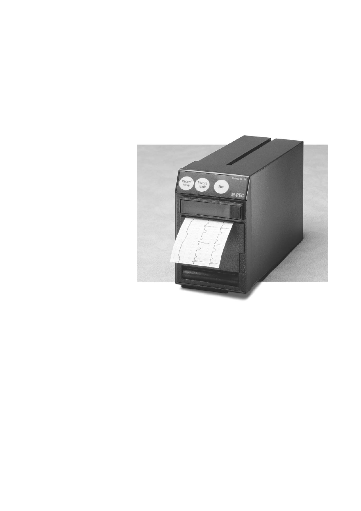
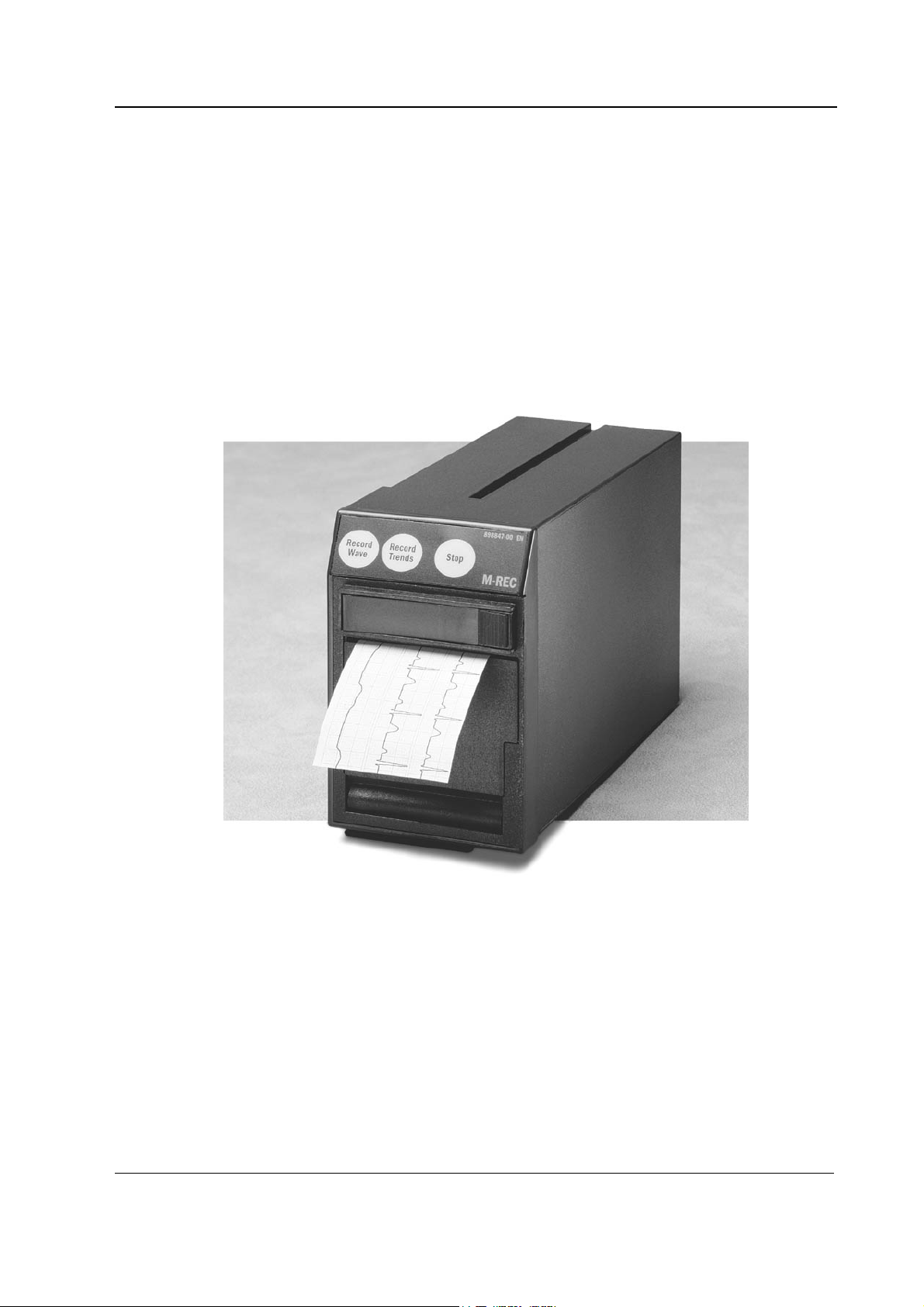
The Recorder Module is a double width plug-in module designed for use with S/5 monitors. The
Recorder Module provides real time printing of waveform and numerical data, and trend data.
The S/5 Compact Monitos may include a built-in recorder. The built-in recorder is technically the
same as the Recorder Module.
NOTE: Printings on thermal paper may be destroyed when exposed to light, heat, alcohol etc. Take
a photocopy for archive.
NOTE: The Recorder Module, M-REC, cannot be used in the Extension Frame, F-EXT4.
Recorder Module, M-REC
Figure 1 Recorder Module, M-REC
1
Document No. 800 1016-1
Page 6

Datex-Ohmeda A/5 monitors
1 SPECIFICATIONS
Module size, W x D x H 75 x 180 x 112 mm / 3.0 x 7.1 x 4.4 in
Module weight 0.9 kg/ 2 lbs
Power consumption 3 W
Principle Thermal array
Print resolution
Vertical 8 dots/mm (200 dots/inch)
Horizontal 32 dots/mm (800 dots/inch) at a speed of 25 mm/s and slower
Paper width 50 mm, printing width 48 mm
Traces Selectable 1, 2, or 3 traces
Print speed 1, 6.25, 12.5, 25 mm/s
2
Document No. 800 1016-1
Page 7
Recorder Module, M-REC
2 FUNCTIONAL DESCRIPTION
2.1 Main components
2.1.1 Recorder board
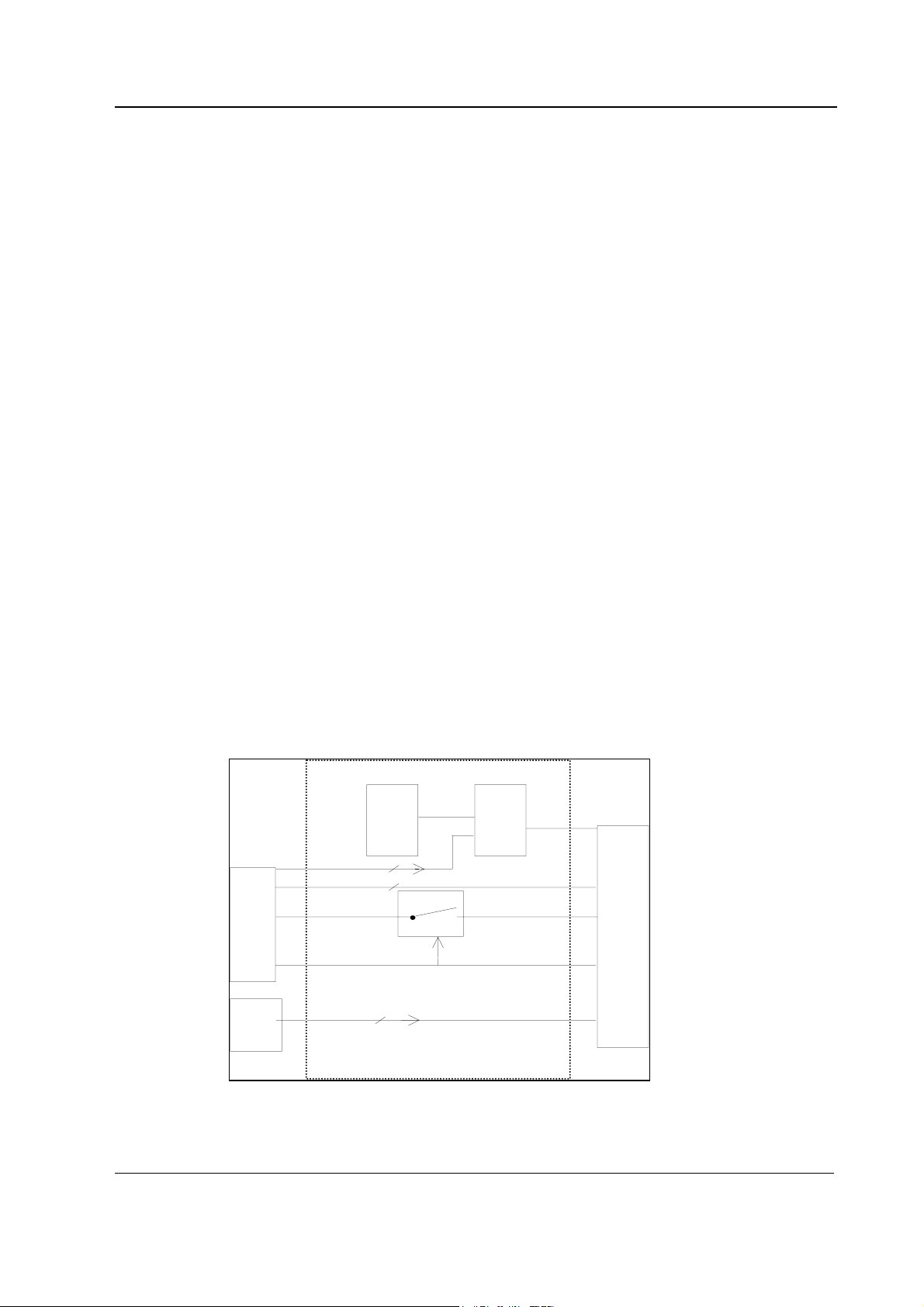
The function of the recorder board is to establish an interface between the recorder unit and main
CPU board in the monitor. The three front panel keys are connected to the recorder unit via the
recorder board. The recorder unit and the recorder board are connected together with a small
connector board and 12-pin flex-strip cable.
External Communication
Communication with the main CPU board is via a +5 V CMOS level RS232 serial interface, with an
RS485 reset.
Reset The differential RS485 reset from the module bus generates a Recorder Unit reset signal on the
Recorder Board. The Recorder Board also generates a power-up-reset, whose time constant is
approximately 0.1 second. The Recorder Unit reset signal is therefore active when either the
Module Bus RS485-reset or the power-up-reset is active.
+5 V priority The recorder unit supply voltage, +15 VREC, is switched on after +5 V is present.
Front panel keys The recorder board can read the three front panel keys and pass their status on to the main CPU
board.
For protect the keypad signals from static discharges, zener diodes and series resistors are used.
Separate pull-up resistors are not needed because pull-up resistors connecting the keypad input
signals to +5 V are fitted inside the recorder.
Recorder Board
Module
mother
board
Front
panel
membrane
switch
Power-up
reset
RS-485-Reset
Serial interface
+15 V
+ 5 V
Switches
Reset
logic
Reset
Recorder
+ 15VREC
Figure 2 Recorder board block diagram
3
Document No. 800 1016-1
Page 8
Datex-Ohmeda A/5 monitors
2.2 Module bus connector
13
25
1
14
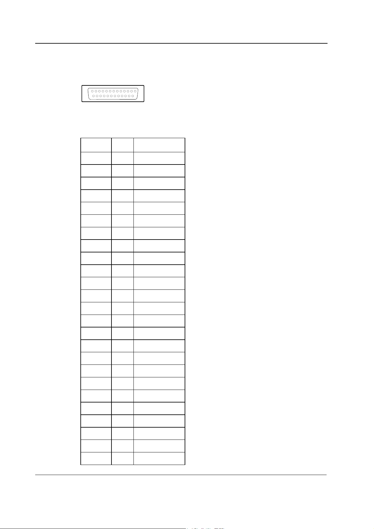
Figure 3 Module Bus connector (X1) pin layout
Table 1 Module Bus connector (X1) pin description
Pin No I/O Signal
1 I RESET_RS485
2 - Not connected
3 I +15 VDIRTY
4 - Not connected
5 - Not connected
6 - Not connected
7 - Ground & Shield
8 I -RESET_RS485
9 O CTSB
10 I RTSB
11 O RXDB
12 I TXDB
13 - Ground & Shield
14 - Not connected
15 I GroundDIRTY
16 - Not connected
17 - Not connected
18 - Not connected
19 - Not connected
20 - Not connected
21 - Not connected
22 - Not connected
23 - Not connected
24 I +5 VDC
25 I +5 VDC
4
Document No. 800 1016-1
Page 9

Recorder Module, M-REC
3 SERVICE PROCEDURES
3.1 General service information
Field service of the Recorder Module, M-REC, is limited to replacing faulty circuit boards or
mechanical parts. Faulty circuit boards should be returned to Datex-Ohmeda for repair.
Datex-Ohmeda is always available for service advice. Please provide the unit serial number, full
type designation, and a detailed description of the fault.
CAUTION Only trained personnel with appropriate equipment should perform the tests and
repairs outlined in this section. Unauthorized service may void warranty of the unit.
3.2 Service check
These instructions include complete procedures for a service check. The service check is
recommended to be performed after any service repair. However, the service check procedures can
also be used for determining possible failures.
The procedures should be performed in ascending order.
The instructions include a check form (Appendix A) which should be filled in when performing the
procedures.
The mark
the procedure.
The procedures are designed for monitors with S/5 monitor software of revision 01. However, most
of the procedures also apply to monitors, which contain some other monitor software
type/revision.
? in the instructions means that the check form should be signed after performing
3.2.1 Recommended tools
Tool Order No. Notes
M-NE(12)STPR/M-ESTPR/M-ESTP
Patient simulator
Screwdriver
3.2.2 Recommended parts
Part Order No. Notes
Recorder paper 74205
• Detach the module box by removing the two screws from the back of the module. Be careful
with the loose latch and spring locking pin.
5
Document No. 800 1016-1
Page 10

Datex-Ohmeda A/5 monitors
1. Check internal parts:
• screws are tightened properly
• cables are connected properly
• EMC covers are attached properly (Rev. 02 ->)
• there are no loose objects inside the module
?
2. Check external parts:
• the front cover and the front panel sticker are intact
• the module box, latch and the spring locking pin are intact
?
• Reattach the module box and check that the latch moves properly.
3. Open the paper compartment hatch and take out the paper roll, if installed.
Remove any paper chaff from the paper compartment.
Clean the thermal printhead and the small glass window in front of the static brush with a
cotton swab dipped in isopropyl alcohol. Avoid contact with the rubber paper roller.
NOTE: Be careful to limit the application of alcohol to the thermal printhead and the
window.
Leave the paper compartment empty and close the hatch.
?
• Turn the monitor on and wait until the normal monitoring screen appears.
Configure the monitor screen so that all required parameters are shown, for example:
Monitor Setup - Screen 1 Setup - Waveform Fields - Field 1 - ECG1
Field 2 - ECG2
Field 3 - P1
Field 4 - P2
Field 5 - PLETH
Field 6 - OFF
• Insert the Hemodynamic Moduleinto a module slot. Connect a patient simulator to
the module and check that all connected parameters are shown on the screen.
6
Document No. 800 1016-1
• Preset recording settings:
Record/Print - Record Waveforms - Waveform 1 - ECG1
Waveform 2 - P1
Waveform 3 - P2
Delay - Off
Paper Speed - 6.25 Mm/S
Page 11

Recorder Module, M-REC
Length --> 30 S
Record Trends - Graphic Trend 1 - Hr
Graphic Trend 2 - P1
Monitor Setup - Install/Service (password 16-4-34) - Installation - Printer & Recorder -
Default Trend - Graph.
Display Trends - Time Scale - 2 h
4. Plug in the Recorder Module. Check that the module goes in smoothly and locks up properly.
?
5. Press the RECORD WAVE key on the module front panel. Check that the message “Recorder:
Out of paper” appears on the screen.
?
6. Open the paper compartment cover. Check that the previous message changes to “Recorder:
Cover open”.
Install a paper roll and close the cover. Check that the message “Recorder: Cover open”
disappears from the screen.
?
7. Press the RECORD WAVE key again and check that the module starts recording the selected
waveforms. Press the STOP key on the module front panel to stop recording.
NOTE: If no recording appears, check that the paper roll is installed correctly - only one side
of the paper is printable.
Press the PRINT TRENDS key and check that the module starts recording graphical trends.
Wait until the recording stops.
?
8. Check that the quality of the recordings is acceptable.
?
9. Press the RECORD WAVE key again and this time wait until the recording stops. Check that
the length of the recorded waveform scale is 18.7 cm (±1.5 cm).
Change the paper speed setting to 1 mm/s:
Record/Print - Record Waveforms - Paper Speed - 1 mm/s
Press the RECORD WAVE key and wait until the recording stops. Check that the length of the
scale is now 3.0 cm (±0.5 cm).
Document No. 800 1016-1
7
Page 12

Datex-Ohmeda A/5 monitors
?
10. Perform an electrical safety check and a leakage current test.
?
11. Check that the module functions normally after performing the electrical safety check.
?
12. Clean the module with suitable detergent.
?
• Fill in all necessary documents.
3.3 Disassembly and reassembly
Disassemble the Recorder Module, M-REC, in the following way. See figure 4.
1. Remove the two screws from the back of the module.
2. Pull the module box slowly rearward and detach it from main body. Be careful with the loose
latch and spring pin.
3. Open the recorder unit paper loading hatch. With a long blade screwdriver loosen the two
screws at the bottom of the recorder unit housing.
4. Disconnect the 50-pin connector from the back of the recorder unit and 5-pin ribbon
keypad connector from the recorder board.
The recorder unit and front panel frame can now be pulled out of the main body. The front panel
frame is pulled out of the recorder by pulling rearward.
The recorder board is attached to the metal chassis with four screws.
CAUTION The recorder board is fixed to the metal chassis at the factory in a definite position.
The recorder board and chassis must therefore not be separated.
To reassemble the module, reverse the order of the disassembly steps.
8
Document No. 800 1016-1
Page 13

4 TROUBLESHOOTING
4.1 Troubleshooting chart
Problem Cause Treatment
Recorder Module, M-REC
Module not responding to front panel
keys, but operates through Recorder
menu.
Recorder will not start.
No error messages shown.
Recorder works but nothing appears
on the paper.
Membrane switch cable loose or
broken.
M-REC: Flex-strip cable broken Check the cable. Replace if
M-REC: Bad contact on connector
board.
M-REC: Module not properly inserted. Reinsert the module properly.
M-REC: Flex-strip cable broken. Check the cable. Replace if
M-REC: Connector board loose. Check connector board
Recorder board faulty. Replace the recorder board.
Recorder unit faulty. Replace the recorder unit.
Active side of the paper downwards. Turn the paper roll over.
Check the cable. Replace the
front panel if necessary.
necessary.
Check contact.
necessary.
connections.
To test which side is active:
Place the paper on a hard
surface and draw a line with a
fingernail - a dark line will
appear on the active (thermal)
side.
Recorder unit faulty. Replace the recorder unit.
Document No. 800 1016-1
9
Page 14

Datex-Ohmeda A/5 monitors
4.2 Messages
Message Explanation
Recorder: out of paper Release paper jam or insert a roll of paper into the recorder.
Recorder: cover open Close the recorder cover correctly.
Recorder: thermal array overheat Recorder overheated. Stop using and allow it to cool down.
Recorder: input voltage low +15 Vrec is too low. Check flex-strip cable and connector board.
Recorder: input voltage high +15 Vrec is too high. Check flex-strip cable and connector board.
Recorder system error
1, 2, 3
Recorder: module removed The module not in place, or a communication error due to a fault in the
System error. Remove the recorder module and reinsert it.
If the problem persists, replace the recorder unit.
module or in the main CPU board.
10
Document No. 800 1016-1
Page 15

5 SERVICE MENU
There is no service menu for the Recorder Module, M-REC.
Recorder Module, M-REC
11
Document No. 800 1016-1
Page 16

Datex-Ohmeda A/5 monitors
6 SPARE PARTS
6.1 Spare parts list
NOTE: Only changed part numbers are listed under later revisions. To find the desired part: check
first the list of the revision that corresponds with your device. If the part is not listed there, check the
previous revision, etc. until you find the right number.
6.1.1 Recorder module, M-REC, Rev. 00
4
1
3
2
5
Figure 4 Exploded view of Recorder Module box and Recorder Module
Item Description Order No. Item Description Order No.
- Membrane keypad 879372 6 Recorder board, M-REC (Rev.00) *(880313) Use 883384
1 Module box (wide) 886168 7 Recorder *90350
2 Spring pin 879182 8 50-pin connector cable, M-REC 879362
3 Latch 879181 9 Metal chassis (879179) Use 883384
4 Cross recess screw M3x8 black 616215 10 Front panel sticker see 6.1.4
5 Front panel unit, M-REC 881328 - - -
NOTE: When part 883384 is used, 50-pin connector cable 879362 is not needed.
6.1.2 Recorder module, M-REC, Rev. 01
Item Description Order No.
9 Metal chassis with recorder board *(881964) Use 883384
6.1.3 Recorder module, M-REC, Rev. 02
Item Description Order No.
9 Metal chassis with recorder board *883384
11 Metal cover plate, M-REC 885292
* this part is recommended for stock
12
Document No. 800 1016-1
Page 17

6.1.4 Recorder module, M-REC, Rev. 03
No new spare parts.
6.1.5 Front panel stickers for AS/3 modules (square buttons)
Item 10
Front panel stickers that are related to the Compact Module type and adaptation:
Adaptation codes: DA=Danish, DE=German, EN=English, ES=Spanish, FI=Finnish,
FR=French, IT=Italian, JA=Japanese, NL=Dutch, NO=Norwegian, PT=Portuguese,
SV=Swedish
Adaptation M-REC
(Rev. 02)
Order No.
DA 892220
DE 880486
EN 879483
ES 884388
FI 888875
FR 880172
IT 886761
JA 888310
NL 886066
NO 893573
PT 895241
SV 885869
Recorder Module, M-REC
6.1.6 Front panel stickers for S/5 modules (round buttons)
Front panel stickers that are related to the Compact Module type and adaptation:
Adaptation codes: DA=Danish, DE=German, EN=English, ES=Spanish, FI=Finnish,
FR=French, IT=Italian, JA=Japanese, NL=Dutch, NO=Norwegian, PT=Portuguese,
SV=Swedish
Adaptation M-REC
(Rev. 03)
Order No.
DA 898857
DE 898848
EN 898847
ES 898851
FI 898854
FR 898849
IT 898852
JA 8000384
NL 898850
NO 898856
PT 898853
SV 898855
13
Document No. 800 1016-1
Page 18

Datex-Ohmeda A/5 monitors
14
Document No. 800 1016-1
Page 19

7 EARLIER REVISIONS
For service information on the earlier revisions, please refer to:
Recorder Module revision 00 Service Manual p/n 880850
Recorder Module revision 01 Service Manual p/n 882580
Recorder Module, M-REC
15
Document No. 800 1016-1
Page 20

Datex-Ohmeda A/5 monitors
16
Document No. 800 1016-1
Page 21

APPENDIX A, Recorder Module, M-REC
APPENDIX A
17
Document No. 800 1016-1
Page 22

Datex-Ohmeda S/5 monitors
18
Document No. 800 1016-1
Page 23

SERVICE CHECK FORM
Recorder Module, M-REC
Customer
APPENDIX A, Service check form
Service
Service engineer Date
OK = Test OK N.A. = Test not applicable Fail = Test Failed
OK N.A. Fail OK N.A. Fail
1. Internal parts 2. External parts
3. Paper compartment
cleaning
Notes
5. Paper recognition 6. Cover state recognition
7. Front panel
membrane keys
Notes
Module type S/N
4. Installation
8. Quality of recording
9. Recording speed
6.25 mm/s 17.2 - 20.2 cm
1.0 mm/s 2.5 - 3.5 cm
10. Electrical safety check
12. Final cleaning
Notes
Used Spare Parts
Signature
11. Functioning after
electrical safety check
Document No. 800 1016-1
A-1(1)
Page 24

Datex-Ohmeda S/5 monitors
A- 2(1)
Document No. 800 1016-1
 Loading...