

Page 1

S/5
Datex-Ohmeda
TM
Dual Pressure Module, M-PP (Rev. 01)
Technical Reference Manual
Datex-Ohmeda Inc.
3030 Ohmeda Drive
53707-7550 MADISON, WIS
USA
Tel. +1-608-221 1551, Fax. +1-608-222 9147
www.us.datex-ohmeda.com
All specifications are subject to change without notice.
Document No. 8001014-1
June 2001
Datex-Ohmeda Division,
Instrumentarium Corp.
P.O. Box 900, FIN-00031
DATEX-OHMEDA, FINLAND
Tel. +358 10 394 11 Fax +358 9 146 3310
www.datex-ohmeda.com
Instrumentarium Corp. All rights reserved.
Page 2

Page 3

Table of contents
TABLE OF CONTENTS
Dual Pressure Module, M-PP
TABLE OF CONTENTS i
TABLE OF FIGURES ii
Introduction 1
1 Specifications 2
1.1 General specifications ..............................................................................................................................2
1.2 Typical performance .................................................................................................................................2
1.3 Technical specifications............................................................................................................................2
2 Functional Description 3
2.1 Measurement principle .............................................................................................................................3
2.2 Main components.....................................................................................................................................3
2.2.1 PP board..........................................................................................................................................4
2.3 Connectors and signals.............................................................................................................................7
2.3.1 Module bus connector......................................................................................................................7
2.3.2 Front panel connectors.....................................................................................................................8
2.3.3 Other connectors..............................................................................................................................8
3 Service Procedures 9
3.1 General service information.......................................................................................................................9
3.2 Service check .........................................................................................................................................10
3.2.1 Recommended tools ......................................................................................................................10
3.3 Disassembly and reassembly..................................................................................................................13
3.4 Adjustments and calibrations..................................................................................................................14
3.4.1 Invasive pressure calibration...........................................................................................................14
4 Troubleshooting 15
4.1 Troubleshooting chart .............................................................................................................................15
4.2 Troubleshooting flowchart .......................................................................................................................16
5Service Menu 17
5.1 PP menu................................................................................................................................................18
5.2 PP calibrations menu..............................................................................................................................19
6 Spare Parts 20
6.1 Spare parts list .......................................................................................................................................20
6.1.1 Dual Pressure Module, M-PP, Rev. 00 .............................................................................................20
6.1.2 Dual Pressure Module, M-PP, Rev. 01 .............................................................................................21
6.1.3 Front panel stickers for AS/3 modules (square buttons) ...................................................................21
6.1.4 Front panel stickers for S/5 modules (round buttons).......................................................................21
7 Earlier Revisions 23
APPENDIX A 25
Service check form A-1
Document No. 8001014-1
i
Page 4

Datex-Ohmeda S/5 monitors
TABLE OF FIGURES
Figure 1 Dual Pressure Module, M-PP.................................................................................................................1
Figure 2 Dual Pressure Module, M-PP, front panel...............................................................................................3
Figure 3 PP board block diagram........................................................................................................................4
Figure 4 Pressure transducer principle of operation.............................................................................................5
Figure 5 Serial communication and opto isolation sections .................................................................................6
Figure 6 Module bus connector (X1) ...................................................................................................................7
Figure 7 M-PP troubleshooting flowchart ..........................................................................................................16
ii
Document No 8001014-1
Page 5
INTRODUCTION
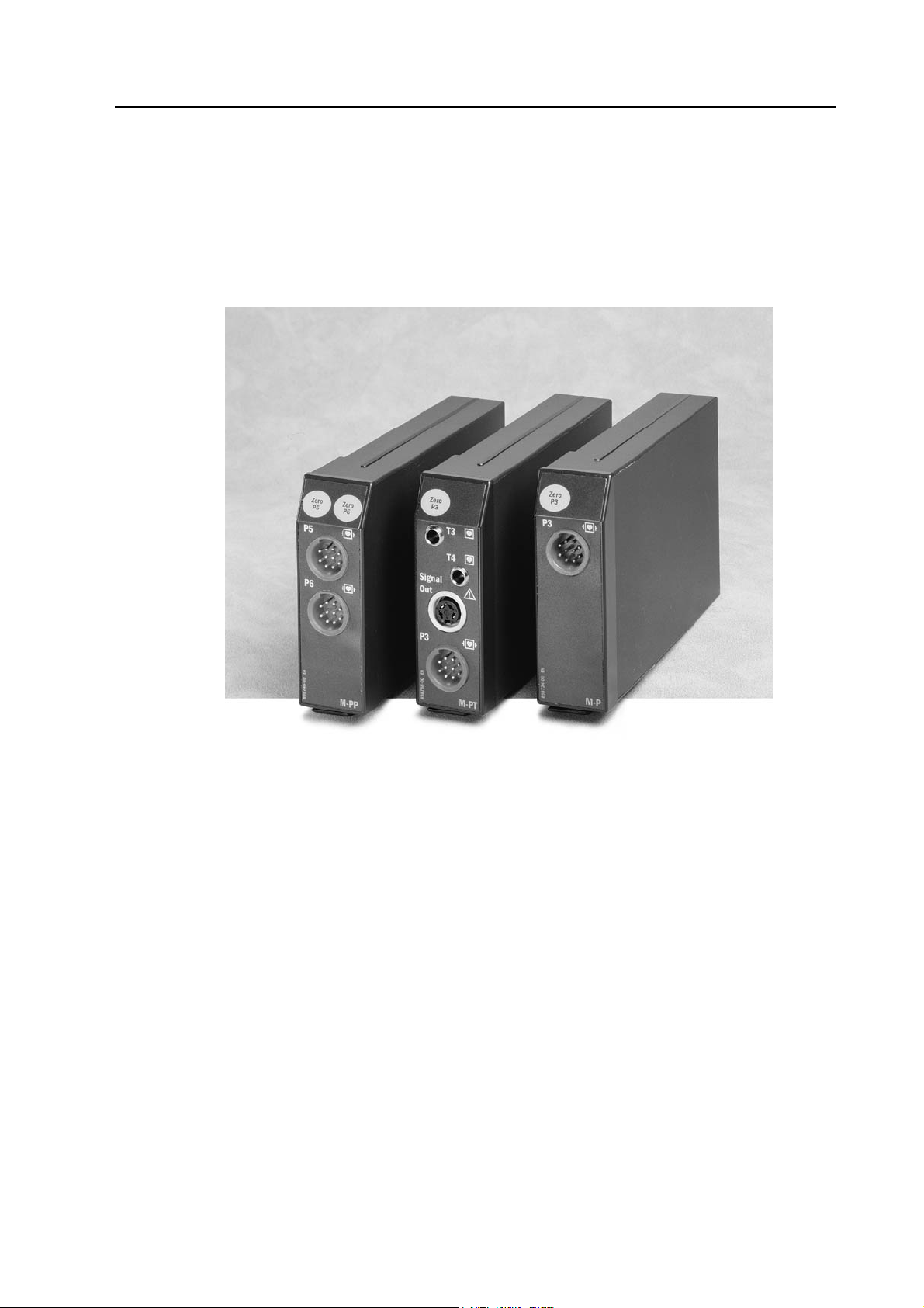
This section provides information for the maintenance and service of the Dual Pressure Module, MPP. The M-PP module is a single width plug-in module designed for use with the S/5 monitors. The
Dual Pressure module provides invasive blood pressure (InvBP) measurement.
Dual Pressure Module, M-PP
Figure 1 Dual Pressure Module, M-PP
1
Document No 8001014-1
Page 6

Datex-Ohmeda S/5 monitors
1 SPECIFICATIONS
1.1 General specifications
Module size, W × D × H 37 × 180 × 112 mm / 1.5 × 7.1 × 4.4 in
Module weight 0.35 kg / 0.8 lbs
Power consumption approximately 3.5 W
1.2 Typical performance
Measurement range -40...+320 mmHg
Accuracy ±5 % or ±2 mmHg, whichever is greater
Zero adjustment range ±150 mmHg
Calibration range ±20 %
Scales Upper limit is adjustable between 10 and 300 mmHg in steps of
Sweep speed 12.5, 25, 50 mm/s
10. Lower limit is 10 % of selected upper limit below zero.
DIGITAL DISPLAY
Range -40...+320 mmHg
Resolution ±1 mmHg
WAVEFORM DISPLAY
Range -30...+300 mmHg
HEART RATE FROM ARTERIAL PRESSURE
Measurement range 30...250 bpm
Resolution 1 bpm
Accuracy ±5 bpm or ±5 %, whichever is greater
1.3 Technical specifications
Accuracy ±5 % or ±2 mmHg, whichever is greater
Transducer and input sensitivity 5 µV/V/mmHg, 5 VDC, 20 mA max current
Nonlinearity < 1 %, 0...200 mmHg
Filter 0...4 - 22 Hz adjustable
Zero set accuracy ±1 mmHg
Calibration resolution ±1 mmHg
Zero time < 15 sec
Protection against electrical shock Type CF defibrillation proof
< 2 %, -40...0 and 200...320 mmHg
2
Document No 8001014-1
DIGITAL DISPLAY AVERAGING
Art and P1 digital displays are averaged over 5 seconds and updated at 5 second intervals. All
other pressures have respiration artifact rejection.
NOTE: The accuracy of the measurement may be different from that specified, depending on the
transducer/probe being used. Please check the transducer/probe specification.
Page 7
2 FUNCTIONAL DESCRIPTION
2.1 Measurement principle
To measure invasive blood pressure, a catheter is inserted into an artery or vein. The invasive
pressure setup, consisting of connecting tubing, pressure transducer, an intravenous bag of normal
saline all connected together by stopcocks, is attached to the catheter. The transducer is placed at
the same level with the heart, and is electrically zeroed.
The transducer is a piezo-resistive device that converts the pressure signal to a voltage. The monitor
interprets the voltage signal so that pressure data and pressure waveforms can be displayed.
2.2 Main components
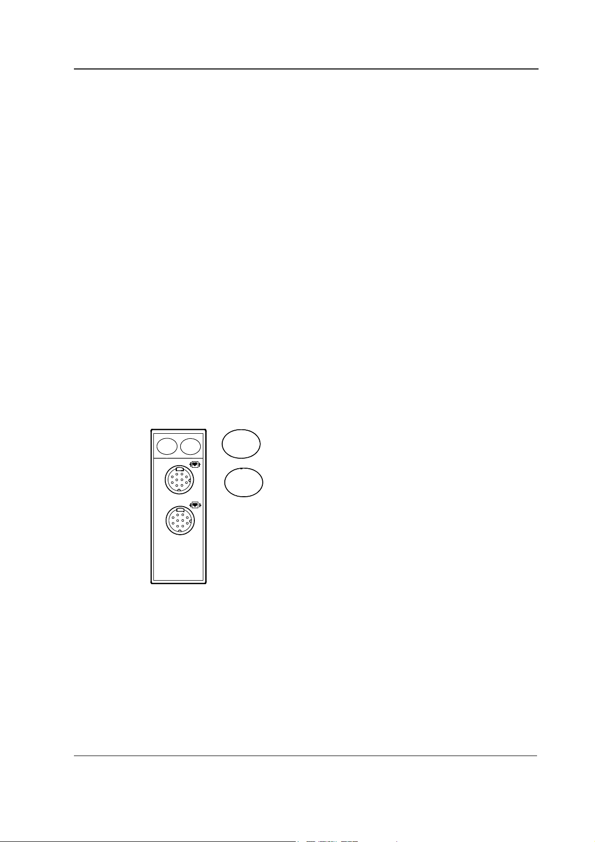
The main components of the Dual Pressure Module, M-PP, are a PP circuit board, a front panel and
a box. The front panel includes two Nicolay-type connectors, P5 and P6, and two direct function
keys, Zero P5 and Zero P6 for pressure zeroing.
Dual Pressure Module, M-PP
Communication between the Dual Pressure Module and the Central Unit is an RS485 serial
interface.
The power supply voltages to the Dual Pressure Module are generated in the power supply section
of the Central Unit. All electrical connections between the Dual Pressure Module and the Central
Unit are via a 25-pin D-connector at the back of the module.
Zero
P5
P5
Zero
P6
P6
Figure 2 Dual Pressure Module, M-PP, front panel
Document No 8001014-1
3
Page 8

Datex-Ohmeda S/5 monitors
2.2.1 PP board
RS485 Driver
for data
Module bus connector
Module data
Module reset
RS485 Driver
for module
reset
Power for
Communication
Power
reset
Power for
module
Power
nonisolation
section
Opto
isolation
Non volatile
memory
Reset
Module
bus
data
Patient isolation
µprocessor
RAM internal 2K
EPROM 48K
RS communication
AD-converter
-8 chn
-12bit
Press AD
INV
PRESS
measuring
unit
external 16K
Isolation
transformer
Power
isolation
section
Front panel
keys
Figure 3 PP board block diagram
Microprocessor unit
The microprocessor uses the Intel 80C196KC-16 CPU which includes three A/D converters and a
UART. The microprocessor uses external memories, an 8-bit data bus, a 16 MHz oscillator, an open
collector reset, and a watchdog timer. The three A/D-converters within the CPU convert the analog
input signals to digital. The internal UART communicates and transfers data between the module
and the CPU board in the monitor.High speed I/O is used to obtain the pulse control sequence
necessary for pulse oximetry measurement. It receives its timing clock signal from the 16 MHz
oscillator.
4
Document No 8001014-1
Patient connectors
Page 9

Invasive blood pressure measurement unit
An isolated +5 V supply is connected to the input of the pressure transducer bridge circuit. From
the bridge circuit output a differential voltage, which depends on blood pressure and input supply
voltage, is calculated using the following formula:
Uout = Uin × Pressure × 5 V
where Uin = 5 V
Uout = 25 V × Pressure [mmHg]
Pressure amplification is performed by the instrumentation amplifier. The gain of the amplifier is
set so that the level of the signal transferred to the A/D converter stays within the measurement
range even when there are circumstantial offsets or offsets caused by the pressure transducer. The
input filter before the amplifier attenuates high frequency disturbances.
Dual Pressure Module, M-PP
Figure 4 Pressure transducer principle of operation
Serial communication
Serial communication between the Dual Pressure Module and the Central Unit is via an RS485
type bus. The communication bus drivers are powered from the Central Unit Module Bus. The
module isolation section (+5 V) is powered from the isolated power supply.
The buffers of the serial communication drivers are controlled by a reset signal such that when the
reset is active the drivers do not transfer data.
Vin
Pressure
transducer
Vout
Input
Filter
Instrumentation
amplifier
G
to AD converter
In addition to the RS485 reset there is a logic power-up reset, which holds for approximately 500
ms regardless of the state of the RS485 reset. A time constant determines the power-up reset time.
The power-up reset also prevents the module from sending data to the Module Bus. The data
transmission rate is 500 kbps.
Document No 8001014-1
5
Page 10

Datex-Ohmeda S/5 monitors
Isolated section
r
o
Receive data
sess
o
Send
r
send
p
e
dat
/receive
Reset
a
Opto isolation
Receive data
Send data
Reset
RS485
Driver
send/r
RS485
Driver
Data
NDa
eceive
Reset in
NReset in
)
nit
s
t
a
u
l
ra
bu
e
nt
ce
to
(modul
to modul
Patient
Isolation
Figure 5 Serial communication and opto isolation sections
There are two opto isolators, one for data and one for the reset signal. Signals are processed on
logical high-low levels even though the output of the opto isolators in the isolation section are
analog signals.
The reset line is an open collector type with a pull-up resistor so that the microprocessor is able to
use its internal watch-dog function.
Power supply section
The module isolated supply voltage is developed from the +15 Vdirty (non-isolated) supply from
the Central Unit power supply.
The isolated power supply is a switched-mode circuit, where an FET switch is controlled by an
oscillator using a bipolar timer. The frequency of the oscillator is approximately 30 kHz with a pulse
ratio 50 %; switching of the FET switch is slow to suppress spurious interference.
A special isolation pulse transformer is used in the circuit. The transformer secondary circuit uses
normal linear regulators except for +5 V which uses a low drop type linear regulator.
6
Document No 8001014-1
Page 11

2.3 Connectors and signals
2.3.1 Module bus connector
Dual Pressure Module, M-PP
13
25
1
14
Figure 6 Module bus connector (X1)
Pin No I/O Signal
1 I RESET_RS485
2 I -15 VDC
3 I +15 VDIRTY
4 I +15 Vin
5 I/O NDATA_RS485
6 I/O DATA_RS485
7 Ground
8 I NRESET_RS485
9 I CTSB
10 O RTSB
11 I RXDB
12 O TXDB
13 Ground
14 I +32 VDIRTY
15 I GroundDIRTY
16 I CTSC
17 O RTSC
18 I RXDC
19 O TXDC
20 ON/STANDBY
21 O PWM_ECG
22 RXDD_RS232
23 TXDD_RS232
24 I +5 VDCin
25 I +5 VDC
Document No 8001014-1
7
Page 12

Datex-Ohmeda S/5 monitors
2.3.2 Front panel connectors
Pressure connectors (P5, P6)
Pin no. Signal
1 Pressure 5/6 +
2 Pressure 5/6 -
3 Polarization - (ground)
4 Polarization +
5Not connected
6Not connected
7Not connected
8Not connected
9 Ground
10 Cable detection
6
3
1
2
9
4
7
0
5
8
2.3.3 Other connectors
Keyboard connector (X3)
Pin no. Signal Notes
1 N/C Not connected
2 PSWITCH for zeroing of P5
3 PSWITCH for zeroing of P6
4 fGND Floating GND
5 fGND Floating GND
Pressure sensor connector (X4)
Pin no.
Board
1 0 PCABEL 5V if cable not connected
2 4 PCURRENT Pulsed supply to sensor
3 3,9 P- Signal from the sensor
4 1 P+ Signal from the sensor
5 2 fGND Floating GND
Pin no.
fr.panel
Signal Notes
X3
1
X4
1
5
5
8
Document No 8001014-1
Page 13

Dual Pressure Module, M-PP
3 SERVICE PROCEDURES
3.1 General service information
Field service of the Dual Pressure Module, M-PP, is limited to replacing faulty circuit boards or
mechanical parts. Faulty circuit boards should be returned to Datex-Ohmeda for repair.
Datex-Ohmeda is always available for service advice. Please provide the unit serial number, full
type designation, and a detailed description of the fault.
CAUTION Only trained personnel with appropriate equipment should perform the tests and
repairs outlined in this section. Unauthorized service may void warranty of the unit.
Document No 8001014-1
9
Page 14

Datex-Ohmeda S/5 monitors
3.2 Service check
These instructions include complete procedures for a service check. The service check is recommended to be performed after any service repair. However, the service check procedures can also be used for determining possible failures.
The procedures should be performed in ascending order.
The instructions include a check form which should be filled in when performing the procedures.
The mark
procedure.
The procedures are designed for monitors with S/5 monitor software of revision 01. However, most
of the procedures also apply to monitors, which contain some other monitor software
type/revision.
? in the instructions means that the check list should be signed after performing the
3.2.1 Recommended tools
Tool Order No. Notes
Patient simulator
Pressure manometer
InvBP transducer
Screwdriver
• Detach the module box by removing the two screws from the back of the module. Be careful
with the loose latch and spring locking pin.
1. Check internal parts:
• screws are tightened properly
10
Document No 8001014-1
• cables are connected properly
• all socket mounted IC’s are inserted properly
• EMC covers are attached properly
• there are no loose objects inside the module
?
2. Check external parts:
• the front cover and the front panel sticker are intact
• all connectors are intact and are attached properly
• the module box, latch and spring locking pin are intact
?
• Reattach the module box and check that the latch is moving properly.
Page 15

Dual Pressure Module, M-PP
• Turn the monitor on and wait until the monitoring screen appears.
Configure the monitor screen so that all the required parameters are shown, for
example:
Monitor Setup - Screen 1 Setup - Waveform Fields - Field 4 - P5
Field 5 - P6
3. Plug in the module, M-PP. Check that it goes in smoothly and locks up properly.
?
• Preset the InvBP measurement settings:
Invasive Pressures - P5 Setup - Label - P5
P6 Setup - Label - P6
4. Enter the service menu:
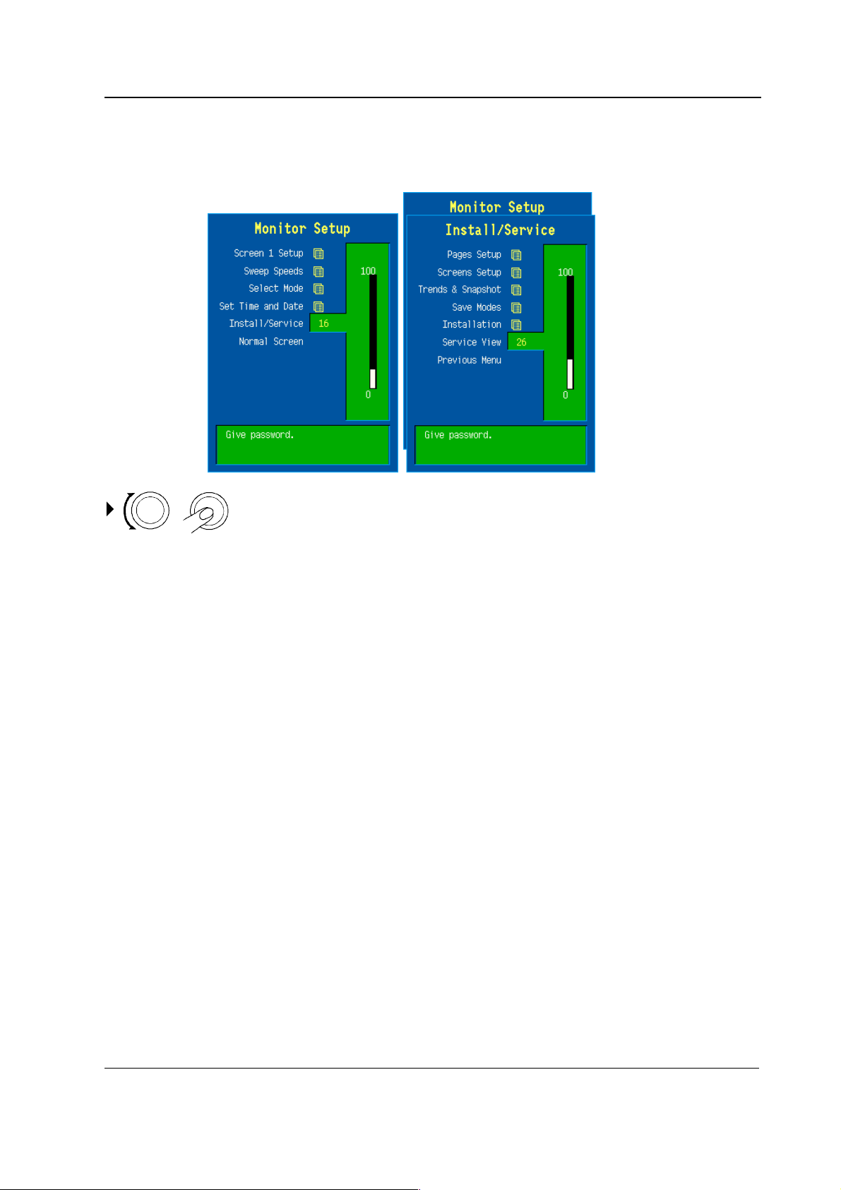
Monitor Setup - Install/Service (password 16-4-34) - Service View (password 26-23-8)
Take down the information regarding PP module software by selecting SCROLL VERS and
turning the ComWheel.
?
5. Enter the PP module service menu (according to the module being tested):
Modules - PP
Check that the “Timeouts”, “Bad checksums” and “Bad c-s by mod” values are not
increasing faster than by 50 per second. Check that the module memories have passed the
internal memory test, i.e. “RAM”, “ROM” and “EEPROM” all show OK.
?
6. Check the front panel membrane keys.
Press each of the keys for at least one second. Check that the key being pressed is
identified, i.e. the text on the service menu for “Button” changes from OFF to ON.
?
7. Check that “Cable” and “Probe” show OFF.
Plug the cable from an invasive blood pressure transducer into front panel connector P5.
Check that the corresponding “Cable” and “Probe” messages show ON and the correct
pressure waveform field appears on the monitor screen.
?
11
Document No 8001014-1
Page 16

Datex-Ohmeda S/5 monitors
8. Calibrate the InvBP channels according to the instructions in the Technical Reference
Manual.
?
9. Check the InvBP channels with a patient simulator.
The settings and checks with a Dynatech Nevada medSim 300 Patient Simulator are:
SENSITIVITY switch position: 5 µV/V/mmHg
ECG - BASE - BPM - 60
Connect channel BP2 to connector P5 and channel BP3 to connector P6.
Zero the InvBP channels by pressing the zeroing keys on the module front panel.
BP - 2 - WAVE - CVP
3 - WAVE - PA
BP - 2 - WAVE - ATM
3 - WAVE - ATM
Check that appropriate InvBP waveforms are shown and the InvBP values are approximately
15/10 mmHg (±2 mmHg) for channel P5 and 25/10 (±2 mmHg) for channel P6.
?
10. Perform an electrical safety check and a leakage current test.
?
11. Check that the module functions normally after performing the electrical safety check.
?
12. Clean the module with suitable detergent.
?
• Fill in all necessary documents.
12
Document No 8001014-1
Page 17

Dual Pressure Module, M-PP
3.3 Disassembly and reassembly
Disassemble the Dual Pressure Module, M-PP, in the following way. See the exploded view of the
module.
1. Remove the two screws from the back of the module.
2. Pull the module box slowly backwards and remove it from the main body. Be careful with the
loose latch and spring locking pin.
3. To detach the PP board, remove the two screws, and disconnect the two ribbon cables from
the front panel.
To reassemble the module, reverse the order of the disassembly steps.
CAUTION When reassembling the module, make sure that all cables are connected properly.
13
Document No 8001014-1
Page 18
Datex-Ohmeda S/5 monitors
3.4 Adjustments and calibrations
3.4.1 Invasive pressure calibration
Perform a pressure calibration whenever the pressure transducer (probe) is replaced with different
type of transducer.
1. Enter the PP service menu (Monitor Setup - Install/Service - Service - Parameters).
2. Enter the Calibrations menu.
3. Connect a pressure transducer with a pressure manometer to the P5/P6 connector. Select
Calibrate P5 or Calibrate P6 from the menu. Leave the transducer at room air pressure.
4. Press the ComWheel to start zeroing.
5. Supply a pressure of 100 mmHg...300 mmHg to the transducer. The recommended pressure
is 200 mmHg.
6. Set the pressure on the display to match the pressure reading on the manometer and press
the ComWheel. A tolerance of ±1 mmHg is allowed.
7. The text 'calibrated' will appear on the display.
14
Document No 8001014-1
Page 19

4 TROUBLESHOOTING
See also the User's Reference Manual for more troubleshooting procedures.
4.1 Troubleshooting chart
Trouble Cause Treatment
Dual Pressure Module, M-PP
Abnormally low
pressure
No pressure Defective transducer. Check the transducer.
“Not zeroed”
message
Zeroing failedmessage
Calibration failedmessage
Transducer wrongly positioned. Check mid-heart level and reposition transducer.
No pressure module plugged in. Check the module.
No selected waveform on screen. Check selected pressure waveforms by pressing
Monitor Setup key and selecting modify
waveforms.
Check that pressure transducer open to patient.
Measurement on, channel not zeroed. Zero the channel.
Unsuccessful zeroing of P5 /P6 (number
field), possibly due to pulsating pressure
waveform.
Offset is > 150 mmHg.
Defective transducer.
Unsuccessful calibration of P5/P6
(number field), possibly due to pulsating
waveform
Gain is beyond the limits (± 20 % of the
default gain).
Open the transducer to air and zero the channel.
Open the transducer to air and zero the channel.
Replace the transducer and zero the channel.
Turn the transducer to sphygmomanometer and
try again (zeroing takes place first).
Replace the transducer.
Out of range < 40
mmHg
Out of range >
320 mmHg
Zero adj. > 100
mmHg
Out of range Measured pressure is beyond the internal
Pressure measurement is beyond
measurement range.
Pressure measurement is beyond
measurement range.
Offset when zeroing is > 100 mmHg (but <
150 mmHg) from the absolute zero of the
module (with default gain). The waveform
may hit the top of the screen and the
numeric display not shown.
measurement range of the module. The
waveform may hit the top of the screen and
the numeric display not shown.
Check the transducer level. Zero the channel.
Check the transducer level. Zero the channel. The
patient may also have high blood pressure.
Check the transducer.
Check the transducer and its level.
Zero the channel.
15
Document No 8001014-1
Page 20

Datex-Ohmeda S/5 monitors
4.2 Troubleshooting flowchart
P o s s i b l y f a u l t y
M - P P m o d u l e
Take all modules
out of the frame
Insert M-PP module
and turn the power on
Does fault
still appear?
Yes
Enter the Service menu
Module-ID
on screen?
Yes
Check front panel key
functions in Service
menu
Do they work?
Yes
No
No
Fault not in M-PP module
No
Does another
module work
in the same slot?
Yes
Replace the PP board
Has EEPROM
failed
Yes
Replace the PP board
16
Document No 8001014-1
No
Check front panel unit
and PP board to
find fault. Replace if
necessary.
No
Has InvBP
measurement
failed
Yes
Figure 7 M-PP troubleshooting flowchart
Replace the PP board
Page 21
5 SERVICE MENU
Dual Pressure Module, M-PP
1. Press the Monitor Setup key.
2. Select Install/Service (password 16-4-34).
3. Select Service (password 26-23-8).
4. Select Parameters.
5. Select PP module.
17
Document No 8001014-1
Page 22

Datex-Ohmeda S/5 monitors
5.1 PP menu
Calibrations See section 5.2 “PP Calibrations Menu.”
Record Data Record Data prints out the service data and circuit board information (id., serial number, and
software id.) on the Recorder Module, M-REC.
Service Data Gain is a coefficient to compensate for gain error. Usually the values for P5 and P6 are between
17000 and 25000.
Zero indicates the offset compensation value for each parameter in the A/D converter. Typically
the values for P5 and P6 are within ±1000. Calibrate if the zero and/or gain value is outside the
ranges.
Cable shows ON when the corresponding cable is connected to the front panel and Probe shows
ON when the corresponding probe is connected to the cable.
Value displays the measured numeric values simultaneously. Pressure value is a real time value
and shown in mmHg.
Button; the front panel key function can be confirmed by pressing the key and checking that OFF
turns to ON.
Timeouts is a cumulative number that indicates how many times the module has not responded to
the monitor's inquiry. Bad checksums is a cumulative number that indicates how many times
communication from the module to the monitor has failed. Bad c-s by mod is a cumulative number
that indicates how many communication errors the module has detected.
The monitor starts counting these items at power up and resets to zero at power off. The nonzero
values do not indicate a failure, but the continuous counting (more than 50 per second) during
normal operation indicates either a serial communication failure or the module is not in place.
18
Document No 8001014-1
RAM indicates the state of the RAM memory. ROM indicates whether the checksum in the EPROM
is in accordance with the software calculated value. EEPROM indicates whether the values stored
in the permanent memory are valid. The state is either OK, Fail or ? (module not in place or a
communication error).
Page 23

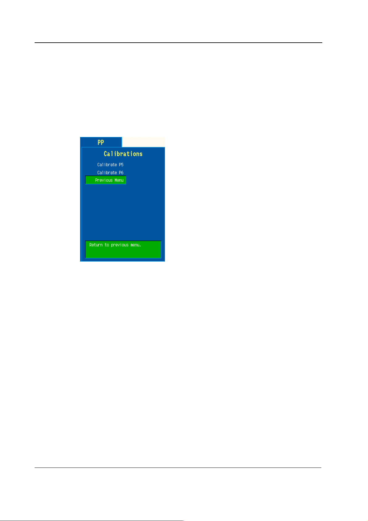
5.2 PP calibrations menu
Calibrate P5 and Calibrate P6
These functions are for calibrating invasive blood pressure channels P5 and P6. The calibrations
require a pressure transducer (with an appropriate cable) and a pressure manometer.
Dual Pressure Module, M-PP
Calibration:
1. Connect the pressure transducer with the pressure manometer to the P5 / P6 connector.
Select Calibrate P5 / Calibrate P6. Leave the transducer at room air pressure.
2. Push the ComWheel to start zeroing.
3. Supply a pressure of 100 mmHg to 300 mmHg to the transducer. The recommended
pressure is 200 mmHg.
4. Set the pressure on the display to match the pressure reading on the manometer and push
the ComWheel.
19
Document No 8001014-1
Page 24

Datex-Ohmeda S/5 monitors
6 SPARE PARTS
6.1 Spare parts list
NOTE: Only changed part numbers are listed under later revisions. To find the desired part: check
first the list of the revision that corresponds your device. If the part is not listed there, check the
previous revision, etc. until you find the right number.
NOTE: Accessories are listed in the Patient Monitor Supplies and Accessories.
6.1.1 Dual Pressure Module, M-PP, Rev. 00
Item Description Order No. Item Description Order No.
1 Module box (single width) 886167 8 PP input board, M-PP 891308
2 Latch 879181 9 Flat cable 891573
3 Spring pin 879182 10 Cross cylinder-head screw M3×12 628700
4
5 PP board, M-PP (Rev. 00) *8000998 12 Membrane keypad 880101
6 Cross cylinder-head screw M3×6 61721 13 Front panel frame 879094
7 Metal frame 891034 14 Front panel sticker see 6.1.2
20
Document No 8001014-1
Cross recess screw M3×8 black
* this part is recommended for stock
616215 11 Fitting plate 879510
Page 25

6.1.2 Dual Pressure Module, M-PP, Rev. 01
Item Description Order No.
5 PP board, M-PP (Rev.-01) 8000998
.
6.1.3 Front panel stickers for AS/3 modules (square buttons)
Front panel stickers that are related to the Compact Module type and adaptation:
Adaptation codes: DA=Danish, DE=German, EN=English, ES=Spanish, FI=Finnish,
FR=French, IT=Italian, JA=Japanese, NL=Dutch, NO=Norwegian, PT=Portuguese,
SV=Swedish
Item no. 14
Adaptation M-PP (Rev. 00), Order No.
DA 892212
DE 891293
EN 889463
ES 891298
FI 891297
FR 891294
IT 891299
JA --
NL 891295
NO 893570
PT 895238
SV 891296
Dual Pressure Module, M-PP
6.1.4 Front panel stickers for S/5 modules (round buttons)
Front panel stickers that are related to the Compact Module type and adaptation:
Adaptation codes: DA=Danish, DE=German, EN=English, ES=Spanish, FI=Finnish,
FR=French, IT=Italian, JA=Japanese, NL=Dutch, NO=Norwegian, PT=Portuguese,
SV=Swedish
Adaptation M-PP (Rev. 01), Order No.
DA 898756
DE 898747
EN 898746
ES 898750
FI 898753
FR 898748
IT 898751
JA 898757
NL 898749
NO 898755
PT 898746
SV 898754
21
Document No 8001014-1
Page 26

Datex-Ohmeda S/5 monitors
22
Document No 8001014-1
Page 27

7 EARLIER REVISIONS
This manual also supports the earlier revisions of the Dual Pressure Module, M-PP
Dual Pressure Module, M-PP
23
Document No 8001014-1
Page 28

Datex-Ohmeda S/5 monitors
.
24
Document No 8001014-1
Page 29

APPENDIX A, Service check form, M-PP
APPENDIX A
25
Document No. 800 014-1
Page 30

Datex-Ohmeda S/5 monitors
26
Document No 8001014-1
Page 31

SERVICE CHECK FORM
Dual Pressure Module, M-PP
Customer
APPENDIX A, Service check form, M-PP
Service
Service engineer Date
OK = Test OK N.A. = Test not applicable Fail = Test Failed
OK N.A. Fail OK N.A. Fail
1. Internal parts 2. External parts
3. Installation
4. Module software
5. Communication and
memories
6. Membrane keys 7. Cable and transducer
8. Calibration 9. Test with patient
PP
Module type S/N
detection
simulator
10. Electrical safety check 11. Functioning after
electrical safety check
12. Final cleaning
Notes
Used Spare Parts
Signature
A1 (1)
Document No. 800 014-1
Page 32

Datex-Ohmeda S/5 monitors
A
2 (2)
Document No 8001014-1
 Loading...