

Page 1
S/5
Datex-Ohmeda
TM
Device Interfacing Solution, N-DISxxx (Rev. 00)
Technical Reference Manual Slot
Datex-Ohmeda, Inc.
P.O. Box 7550,
Madison, WI 53707-7550
U.S.A.
Tel. +1-608-221 1551
Fax +1-608-222 9147
mailto:product.support.ussub@us.datex-ohmeda.com
www.us.datex-ohmeda.com
Document No. 896 616-1
November, 2001
Datex-Ohmeda Division,
Instrumentarium Corp.
P.O. Box 900, FIN-00031
DATEX-OHMEDA, FINLAND
Tel. +358 10 394 11 Fax +358 9 146 3310
www.datex-ohmeda.com
Instrumentarium Corp. All rights reserved.
Page 2

Page 3

Table of contents
TABLE OF CONTENTS
TM
S/5
TABLE OF CONTENTS i
TABLE OF FIGURES ii
INTRODUCTION 1
1 SPECIFICATIONS 3
Device Interfacing Solution, N-DISxxx (rev. 00)
1.1 Environmental specification...................................................................................................................3
1.1.1 Protection against ingress of liquids ............................................................................................3
1.2 Technical specifications ........................................................................................................................3
1.2.1 General......................................................................................................................................3
1.3 Electrical specification ..........................................................................................................................4
1.4 Maximum power consumption...............................................................................................................4
1.5 Module communication.........................................................................................................................4
2 FUNCTIONAL DESCRIPTION 5
2.1 Main components .................................................................................................................................5
2.2 DIS module...........................................................................................................................................6
2.3 Connections .........................................................................................................................................7
2.4 Connectors and signals .........................................................................................................................8
2.5 Interfaced devices, parameters and communication...............................................................................9
3 SERVICE PROCEDURES 11
3.1 General service information.................................................................................................................11
3.2 Service check......................................................................................................................................11
3.2.1 Visual inspection......................................................................................................................12
3.2.2 Functional inspection ...............................................................................................................12
4 TROUBLESHOOTING 15
4.1 LED indicators.....................................................................................................................................15
4.1.1 Green LED................................................................................................................................15
4.1.2 Yellow LED ...............................................................................................................................15
4.2 Quick functional check ........................................................................................................................15
5 DEVICE INTERFACING SOLUTION MENUS 17
5.1 DIS Status menu.................................................................................................................................17
5.1.1 Interfacing................................................................................................................................17
5.1.2 Status Page .............................................................................................................................18
5.2 Service Menu......................................................................................................................................19
5.2.1 DIS Interfacing .........................................................................................................................19
6 SPARE PARTS 21
7 EARLIER REVISIONS 23
APPENDIX A 25
Appendix A: SERVICE CHECK FORM ..............................................................................................................A–1
Document No. 896 616-1
i
Page 4

Datex-Ohmeda S/5 monitors
TABLE OF FIGURES
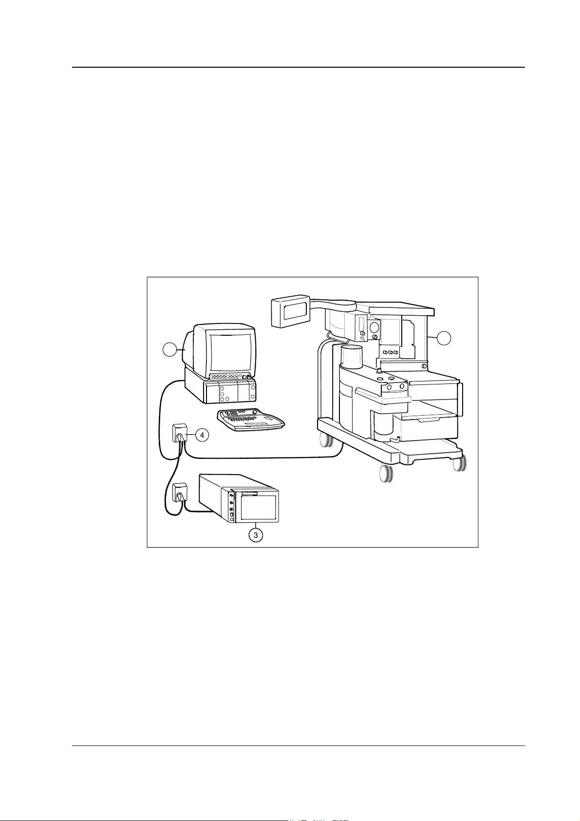
Figure 1 Example of interfacing via the Device Interfacing Solution, N-DISAEST and N-DISRGM ............................1
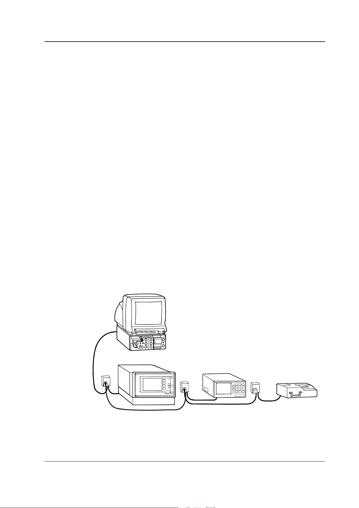
Figure 2 Implementation of Device Interfacing Solution .......................................................................................5
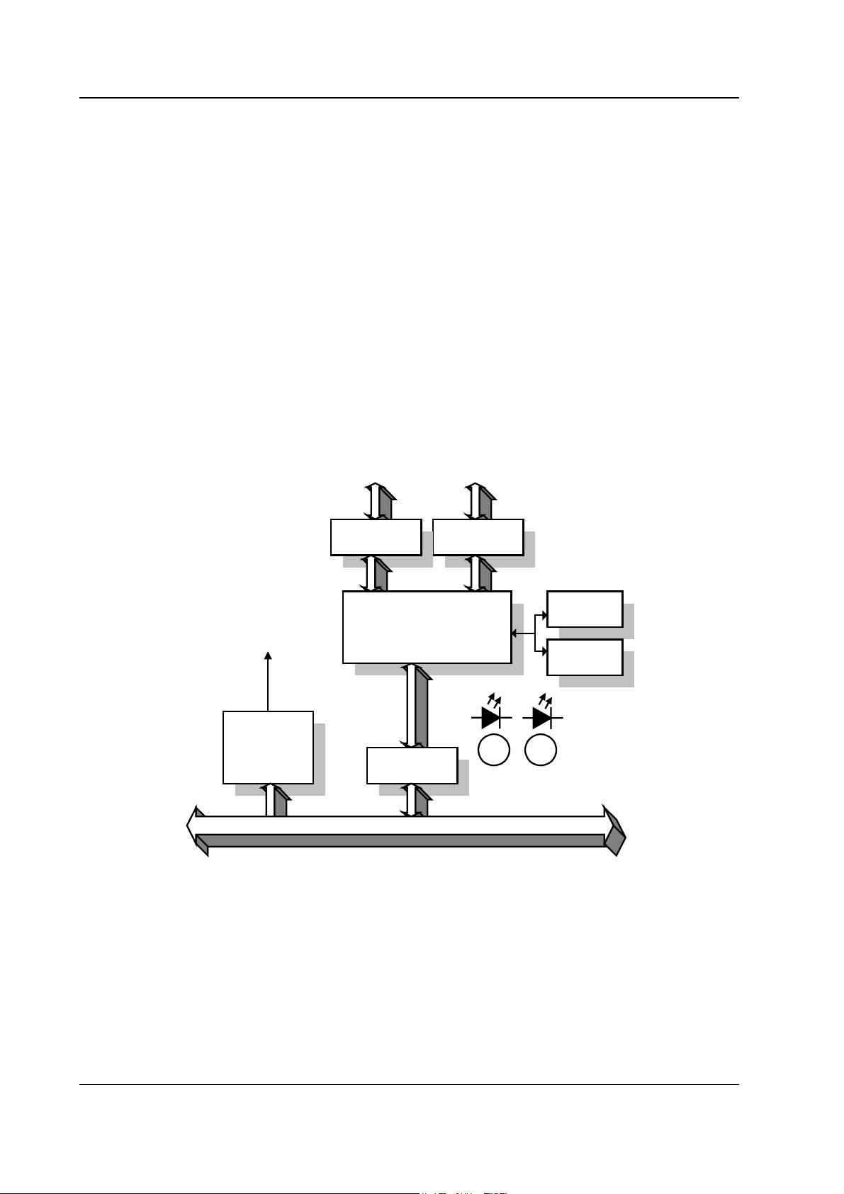
Figure 3 DIS module ..........................................................................................................................................6
ii
Document No. 896 616-1
Page 5
INTRODUCTION
This Technical Reference Manual Slot provides information for the maintenance and service of the
Device Interfacing Solution, N-DISxxx. Please see also related Technical Reference Manual for
information related to system e.g. related documentation, conventions used, symbols on
equipment, safety precautions, system description, system installation, interfacing, functional
check and planned maintenance.
The purpose of the Device Interfacing Solution is to produce a data connection between an external
bedside device and an S/5 monitor.
The N-DISxxx is a new interfacing solution and works beside the previous interface solutions, B-INT
and M-INT that are still available.
Up to 10 devices can be connected simultaneously via device specific N-DISxxx modules.
S/5 Device Interfacing Solution, N-DISxxx (rev. 00)
2
1
Figure 1 Example of interfacing via the Device Interfacing Solution, N-DISAEST and
N-DISRGM
(1) Datex-Ohmeda S/5 Anesthesia Monitor (with the L-ANE01(A) software)
(2) Aestiva3000 anesthesia machine
(3) RGM monitor
(4) DIS module (max. 10 pcs)
1
Document No. 896 616-1
Page 6

Datex-Ohmeda S/5 monitors
2
Document No. 896 616-1-1
Page 7

1 SPECIFICATIONS
1.1 Environmental specification
Operating temperature +10...+35 °C (50...95 °F)
Storage and transport temperature -10...+50 °C (14...122 °F)
Relative humidity 10...90 % (non condensing)
Atmospheric pressure 660...1060 hPa
1.1.1 Protection against ingress of liquids
According to IEC/EN 60592 class IPX 1.
DIS module must always be used in a vertical position to prevent water from entering the module.
S/5 Device Interfacing Solution, N-DISxxx (rev. 00)
(66...106 kPa/660...1060 mbar/500...800 mmHg)
1.2 Technical specifications
1.2.1 General
Max 10 DIS modules or 10 m (393 in) cable length.
Module
Size (W × D × H) 60 × 27 × 85 mm/2.4 × 1.1 × 3.4 in
Weight 0.1 kg/0.2 lbs
Bus cables
8 pin Hirose HR12/HR212 connector
Material black PVC
Lenght/Weight 1 m/47 g (39 in/3.3 ft./0.104 lbs.)
Device cables
Depends on device.
Material elastollan
2 m/85 g (79 in/6.6 ft./0.187 lbs.)
6 m/220 g (236 in/19.7 ft./0.485 lbs.)
Lenght 0.5...1 m (19...39 in/1.6...3.3 ft.)
Weight 40...70 g (0.088...0.154 lbs.)
3
Document No. 896 616-1
Page 8

Datex-Ohmeda S/5 monitors
1.3 Electrical specification
There is no isolation in DIS module. Interfaced device, DIS module and monitor must be situated in
the same patient environment (as defined in IEC 60601-1-1).
WARNING Connecting electrical equipment together, or using the same extension cord for
more than one device, may cause their leakage currents to exceed the limit
specified in relevant safety standards. Always make sure that the whole
combination complies with the international safety standard IEC 60601-1-1 for
medical electrical systems and with the requirements of local authorities.
1.4 Maximum power consumption
600 mW (75 mA @ 8 V)
1.5 Module communication
Bus communication speed is 500 kbps. RS422 implementation.
Device communication speed depends on the interfaced external device. RS232 implementation.
4
Document No. 896 616-1-1
Page 9
S/5 Device Interfacing Solution, N-DISxxx (rev. 00)
2 FUNCTIONAL DESCRIPTION
The S/5™ Device Interfacing Solution provides a seamless link between external patient care
devices and the Datex-Ohmeda S/5 monitoring system. You can interface simultaneously up to ten
external devices: monitors, ventilators, blood gas analyzers, etc.
The Device Interfacing Solution is designed for use with S/5 Anesthesia Monitor and Compact
Anesthesia Monitor, and S/5 Critical Care Monitor and Compact Critical Care Monitor. The Device
Interfacing Solution (DIS) is only compatible with the S/5 Anesthesia and S/5 Critical Care Monitor
when the monitor has B-UPI4(NET) and B-CPU4 boards installed. Also, DIS is only compatible with
the S/5 version (i.e. F-CM(REC)1 frame) of the Compact Anesthesia and Compact Critical Care
monitor. In addition, the S/5 Monitors must be equipped with DIS compatible main software. The
Device Interfacing Solution, N-DISxxx can not be used with AS/3 and CS/3 Compact Monitors.
WARNING The manufacturer guarantees a reliable functioning of the devices with tested
software versions only. Always refer to the Installation guide accompanying the
DIS module and verify the compatibility before use.
2.1 Main components
The implementation of Device Interfacing Solution can be divided into five parts:
• Device specific software
• Device specific module
• Device specific cable
• Bus cables
• Software in Datex-Ohmeda monitor
Datex-Ohmeda Monitor
DIS Module bus
DIS
Module
DIS
Module
DIS
Module
Device # 1
Device # 2
Figure 2 Implementation of Device Interfacing Solution
External
serial
format
Document No. 896 616-1
Device # 3
5
Page 10
Datex-Ohmeda S/5 monitors
2.2 DIS module
A DIS module receives data from an external device, modifies the data to a suitable mode and
sends the data to the connected monitor. The main board contains the power supply with current
limiter, microcontroller, reset circuits, memory and serial communication buffers. The board
communicates with the Datex-Ohmeda monitor through the DIS bus.
A DIS module consists of:
• Power supply with current limiter and reset circuit parts
• Microcontroller H8, internal and external RAM, non volatile memory etc.
• Programming connection
• Device communication connection and RS232 driver
• Bus communication connection and RS422 driver
• LEDs, that indicate the status of the communication
• Device specific software
to programming device to external device
+ 5 V
Power
Current limit
Rese t
Figure 3 DIS module
Pr o g r a mmi n g
Controller H8
Flash
RAM
RS422 buff ers
DIS Bus
RS232 buff ers
SRAM
EEPROM
LEDs
Gree n Yellow
6
Document No. 896 616-1-1
Page 11

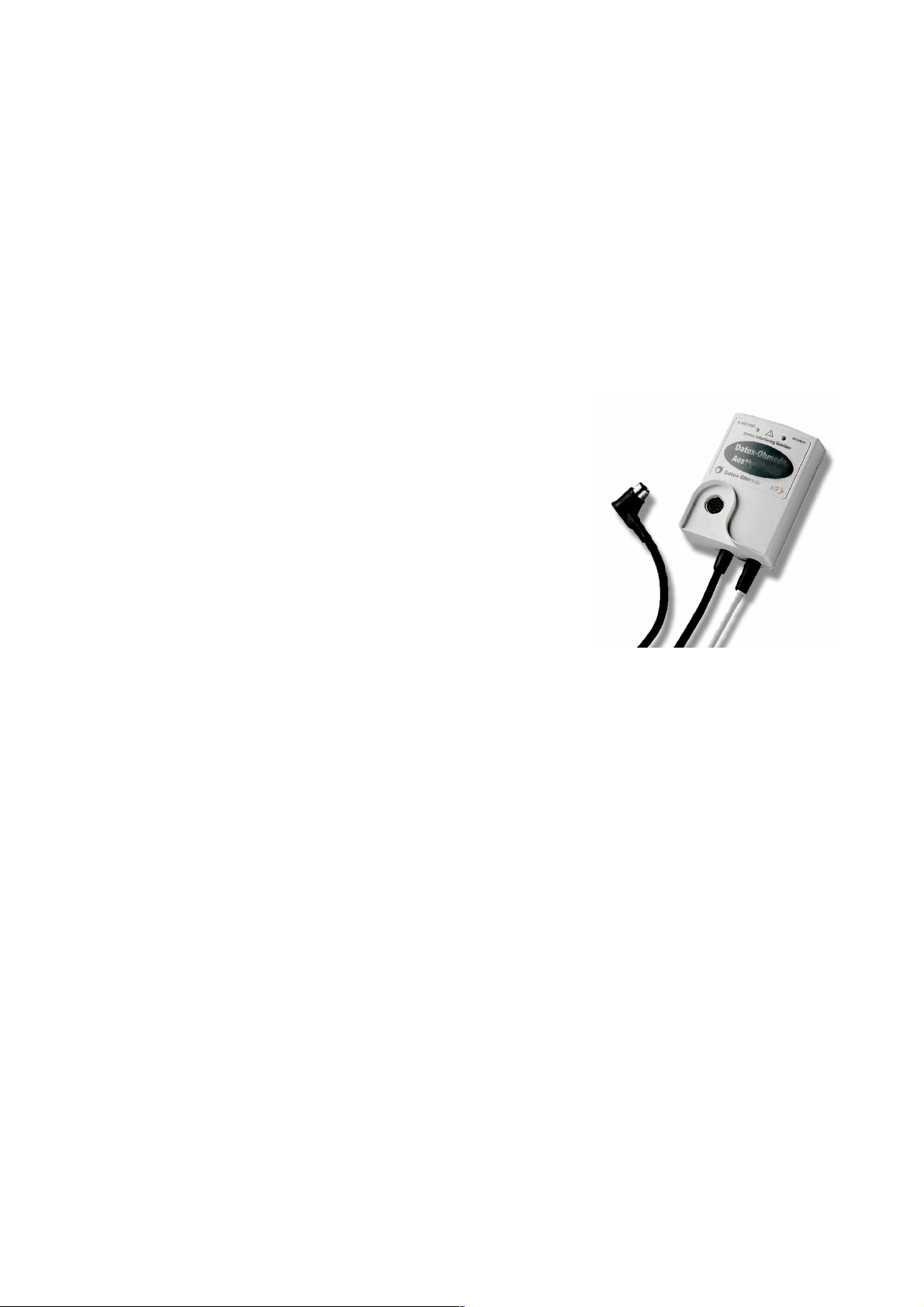
2.3 Connections
Connect the device specific cable to the external device and the bus cable to the D-O monitor’s BUPI4(NET) board, or to another DIS module.
1
S/5 Device Interfacing Solution, N-DISxxx (rev. 00)
2
3
5
4
(1) Label specifying the external device
(2) LED indicators
(3) Bus cable from another DIS module (if used)
(4) Device specific cable to the external device
(5) Bus cable to the D-O monitor’s B-UPI4(NET) board (or to another DIS module)
Document No. 896 616-1
7
Page 12

Datex-Ohmeda S/5 monitors
2.4 Connectors and signals
Male bus cable connector
12
345
76
8
Pin no Signal Color
1 Data from UPI + brown
2 Data from UPI - red
3 VDD 9 V to 18 V (max 1 A) orange
4 GND yellow
5 VCC 7 V to 8 V (max 1 A) blue
6 GND grey
7 Data to UPI + white
8 Data to UPI - black
8
Document No. 896 616-1-1
Page 13

S/5 Device Interfacing Solution, N-DISxxx (rev. 00)
2.5 Interfaced devices, parameters and communication
Ventilator interfaces
Device Device set values for
trends
Datex-Ohmeda
SmartVent 7900
Vent. mode, I:E ratio,
RR, TV, PEEP, Pinsp,
InspPause
Datex-Ohmeda
Aestiva /5
Aestiva /5 7100
Vent. mode, I:E ratio,
RR, TV, PEEP, Pinsp,
InspPause
Aestiva /5 Compact
Dräger Evita 4 FiO2, Vent. mode, I:E
ratio, RR, TV, PEEP,
Pinsp
Nellcor Puritan
Bennett 7200
Nellcor Puritan
Bennett 840
Vent. mode, RR, TV,
PEEP, O
setting
2
Vent. mode, I:E ratio,
RR, TV, PEEP, O
2
setting.
Measured numeric values Waveforms
, TVexp, MV, RR, Pmean,
FiO
2
Paw, Flow, Vol N-DIS7900
Ppeak, Pplat
FiO2, TVexp, MV, RR, Pmean,
Paw, Flow, Vol N-DISAEST
Ppeak, Pplat
FiO2, EtCO2, TVexp, MV,
Paw, Flow, Vol N-DISEV4
MVspont, RR, Ppeak, Pplat,
Pmean, Raw, Compl, PEEPi
expTV, expMV, expMVspont,
RR, Ppeak, Pplat, Pmean,
Dyn. Raw, Dyn. Compl,
I:E ratio
expTV, expMV, expMVspont,
RR, Ppeak, Pplat, Pmean,
I:E ratio
N-DIS7200
N-DIS840
Siemens Servo 300 CMV freq set, SIMV freq
set, Insp. Time,
Pause time, MV, PEEP,
Pinsp, Plimit,
Vent mode, O
concentr
2
insp, TV exp, TV insp, MV
O
2
exp, MV insp, RR, Ppeak,
Pplat, Pmean, PEEP,
PAmbient
Paw, Flow, Vol N-DISS300
Document No. 896 616-1
9
Page 14

Datex-Ohmeda S/5 monitors
Monitor interfaces
Device Numeric values
Abbott Qvue/Q2 CO, CCO, Tblood, and SvO2 (Q2 only) N-DISQVUE
Abbott Oximetrix 3 CO, SvO
2
N-DISOXIM3
Aspect A-2000 BIS Monitor BIS, SQI, EMG N-DISA2000
Baxter Vigilance CO, CCO, SvO2, TBLOOD N-DISVIGIL
Datex-Ohmeda RGM CO2, O2, N20, AA, RR, SpO2, HR, Paw, TV, MV N-DISRGM
Datex-Ohmeda Tonocap PgCO
Datex-Ohmeda
Capnomac, Capnomac II, EtCO
2
, FiCO2, EtO2, FiO2, EtN2O, FiN2O, EtAA, FiAA, AA selection,
2
N-DISTONO
N-DISWHITE
RR, PAmbient
Satlite, Satlite trans and
Pulse, SpO
2
Satlite Plus
Oscar II, Oscar oxy, Cardiocap
EtCO2, FiCO2, EtO2, FiO2, EtN2O, FiN2O, RR, Pulse, SpO2%
1GS and Cardiocap 2GS
Capnomac Ultima EtCO2, FiCO2, EtO2, FiO2, EtN2O, FiN2O, EtAA, FiAA, AA selection,
RR, PAmbient, Auto id AA, Pulse, SpO
%, MV exp, MV insp, TV
2
exp, TV insp, Compl, Ppeak, Pplat, PEEP, I:E
Normocap CD-200 EtCO2, FiCO2, EtN2O, FiN2O, RR, PAmbient
Multicap, Normocap CD2-02, EtCO2, FiCO2, EtO2, FiO2, EtN2O, FiN2O, RR, PAmbient
Heart-lung machines
Device Device set values for
trends
Jostra HL20 bypass on, bypass off,
aorta closed, aorta open
Bloodgas analyzers
Device Numeric values
AVL Opti CCA
pH, PCO2, PO2, ctHb, SO2, barometric pressure, HCO3, BE, Temp,
Kalium, Natrium, O
Ct
2
Measured numeric values in trends
speed, flow rate,
systolic pressure, diastolic pressure,
mean arterial pressure, FiO2, FiCO
2,
cardioplegia amount
N-DISHL20
N-DISOPT
10
Document No. 896 616-1-1
Page 15

S/5 Device Interfacing Solution, N-DISxxx (rev. 00)
3 SERVICE PROCEDURES
3.1 General service information
Field service of the Device Interfacing Solution is limited to replacing faulty mechanical parts that
are listed as spare parts. Faulty DIS modules should be returned to Datex-Ohmeda for repair.
Datex-Ohmeda is always available for service advice. Please provide the unit serial number, full
type designation, and a detailed description of the fault.
CAUTION Only trained personnel with appropriate equipment should perform the tests and
repairs outlined in this section. Unauthorized service may void warranty of the unit.
3.2 Service check
These instructions include complete procedures for a service check for Datex-Ohmeda Device
Interfacing Solution. The service check is recommended to be performed after any service repair,
however, the service check procedures can be used also for determine possible failures.
The instructions include an Appendix A: Service Check form, to be filled in when performing the
corresponding procedures.
The symbol
check form.
The procedures are designed for monitors running the S/5 monitor software of rev. 01.
? in the instructions means that the performed procedure should be signed in the
Recommended tools
Tool Order No. Notes
Screwdrivers
Recommended parts
No recommended parts.
11
Document No. 896 616-1
Page 16

Datex-Ohmeda S/5 monitors
3.2.1 Visual inspection
• Disconnect the DIS module from the DIS bus and from the interfaced external device.
1. Internal inspection
— Disassemble the DIS module.
— Make sure there are no loose parts inside the DIS module.
— Check the screws holding the PC board are tightened properly.
— Check that the cables are attached properly and the connectors are intact.
2. External inspection
— Check that the DIS module case and label are clean and intact.
— Reassemble the DIS module.
?
— Check that the screws for the DIS module case are secured properly.
— Check that the bus cable connector is intact.
— Check that the DIS bus and device specific cables are intact.
?
3.2.2 Functional inspection
3. DIS module interface status
— Connect the DIS module to the DIS bus and to the external device that is specified in
the DIS module label, if possible. Turn on the interfaced external device.
— Check that no error messages are displayed on the monitor screen.
— Check via the Interfacing menu that the connected DIS module status is correct:
Monitor Setup - Interfacing - Status Page
— Check that the waveforms and numeric fields are transferred to the monitor
according to the configuration.
?
4. Recognition of interface
12
Document No. 896 616-1-1
— Disconnect the DIS bus cable and check that the ‘[device name] module removed’
message appears onto the monitor screen. Reconnect the cable.
— Turn off the external device (if possible) and check that the ‘[device name]
disconnected from module’ message appears onto the screen. Turn the external
device back on again.
?
Page 17

S/5 Device Interfacing Solution, N-DISxxx (rev. 00)
5. DIS module service menu
— Enter the service menu
Monitor Setup – Install/Service (password 16-4-34) –
Service (password 26-23-8) –
Parameters – More – DIS Interfacing
— Check that the menu displays submenus for all connected DIS modules.
— Enter the corresponding DIS module service menu and check that the displayed
information corresponds with the information on the DIS module labels.
— Check that the DIS bus voltage is between 6.00...8.00 V.
— Check that the DIS module timeout and checksum error values do not increase more
than by 50 per second.
— Check that the status of each DIS module memory indicates OK.
?
6. Perform the electrical safety test and leakage current test. Check that the DIS module
functions normally after the tests.
?
7. Clean the DIS module, the bus cable and the device specific cable with a suitable
detergent.
?
8. Fill up all the necessary documents.
13
Document No. 896 616-1
Page 18

Datex-Ohmeda S/5 monitors
14
Document No. 896 616-1-1
Page 19

4 TROUBLESHOOTING
4.1 LED indicators
S/5 Device Interfacing Solution, N-DISxxx (rev. 00)
4.1.1 Green LED
The meaning of the green LED is to indicate that communication between the monitor and DIS
module and communication between the DIS module and external device is working properly.
When all cables are connected and the connected devices are on, the LED should be lit
continuously.
4.1.2 Yellow LED
The meaning of the yellow LED is to alert user. The yellow LED is lit when any of the following
conditions becomes true:
1. The DIS module is connected to the DIS bus but the external device is not connected.
2. The external device is in power off state.
3. The external device is not selected from the interfacing menu as an active source of data.
NOTE: The meaning of the yellow LED varies with some external devices. See Installation Guide
delivered with the DIS module.
4.2 Quick functional check
You have two ways for checking the functioning of the Device Interfacing Solution:
• Press the Monitor Setup key and select Interfacing and open the Status Page menu.
The status page shows you the current communication status of the interfacing modules
connected to the bus (1...10 pcs).
Document No. 896 616-1
15
Page 20

Datex-Ohmeda S/5 monitors
NOTE: The status message ‘Connected’ appears onto the monitor screen after you have connected
the external device to the DIS module and turned it on, if the monitor and DIS module have already
been initialized.
• Check the LED indicators on the DIS module (the green LED indicates the physical
connections, the yellow LED software selections):
GREEN YELLOW INDICATION
lit dark
●
physical connections between the monitor, DIS module and external
device are in order and the device has been selected in the menu
dark
●
lit physical connections between the monitor, DIS module and external
device are not in order; the external device has not been selected in
the menu (see the User’s Reference Manual of the monitor)
lit lit physical connections between the monitor, DIS module and external
device are in order but the external device has not been selected in
the menu (see the User’s Reference Manual of the monitor)
dark
●
dark
●
the DIS module is not connected to the monitor
16
Document No. 896 616-1-1
Page 21

S/5 Device Interfacing Solution, N-DISxxx (rev. 00)
5 DEVICE INTERFACING SOLUTION MENUS
5.1 DIS Status menu
Monitor Setup - Interfacing - Status Page
5.1.1 Interfacing
For selecting the parameter data source:
• Select the desired measurement parameter (e.g., Gases).
• Select the desired source by name (e.g., Aest).
NOTE: The name of the device is visible on the list only if the device is correctly connected to the
module.
17
Document No. 896 616-1
Page 22

Datex-Ohmeda S/5 monitors
5.1.2 Status Page
Status Page
The selection Next page is available, if more than
8 DIS modules are connected to the DIS bus
simultaneously.
Interfaces
The menu displays a list of all connected DIS
modules and the statuses of the corresponding
external devices.
If the bus voltage is too low you can not add more
devices. ‘DIS module bus voltage low. Do not add
more devices or reduce cable length’ message
appears.
18
Document No. 896 616-1-1
Page 23

5.2 Service Menu
S/5 Device Interfacing Solution, N-DISxxx (rev. 00)
Monitor Setup - Install/Service (password 16-4-34) - Service (password 26-23-8) -
Parameters – More – DIS Interfacing
5.2.1 DIS Interfacing
The menu displays submenus for all connected DIS
modules.
19
Document No. 896 616-1
Page 24

Datex-Ohmeda S/5 monitors
5.2.2 DIS Module specific page
Service Data
Product name: DIS module name.
Product type: DIS module type.
Driver sw id: DIS module software and its release date.
Short product name: DIS module name.
Module serial number: DIS module serial number.
HW card type: PCB type.
HW id: DIS module PCB identification number.
HW test date: DIS module PCB testing date.
Unit serial number: DIS module PCB serial number.
Comment field: Indicates the status of the external device.
bus voltage: DIS bus voltage, measured by the UPI4(NET)
board or the Central Processing Board in S/5 Compact
Monitor. The value should normally be within 6…8 V.
tout: DIS module timeouts, seen by the monitor. The value
should not increase more than by 50 per second.
cse: DIS module checksum errors, seen by the monitor. The
value should not increase more than by 50 per second.
rx: The number of data packets from the external device
received by the DIS module.
rx err: The number of data errors from the external device
received by the DIS module.
tx: The number of data packets to the external device sent
by the DIS module.
Ram: Status of DIS module RAM memory.
Rom: Status of DIS module ROM memory.
EEPROM: Status of DIS module EEPROM memory.
20
Document No. 896 616-1-1
Page 25

6 SPARE PARTS
S/5 Device Interfacing Solution, N-DISxxx (rev. 00)
21
Document No. 896 616-1
Page 26

Datex-Ohmeda S/5 monitors
Item Description Order no.
6 Label for Nellcor P-B 7200 N-DIS7200 897207
6 Label for Nellcor P-B 840 N-DIS840 8002435
6 Label for Datex-Ohmeda Aestiva/5 N-DISAEST 8002595
6 Label for Abbot Q-Vue/Q2 N-DISQVUE 897210
6 Label for Datex-Ohmeda Tonocap N-DISTONO 897209
6 Label for Datex-Ohmeda Smartvent 7900 N-DIS7900 8002598
6 Label for AVL Opticca N-DISOPT 897543
6 Label for Abbot Oximetrix 3 N-DISOXIM3 8000983
6 Label for Siemens Servo N-DISS300 8000392
6 Label for Baxter Vigilance N-DISVIGIL 8002434
6 Label for Datex-Ohmeda whiteline monitors N-DISWHITE 8000405
Device specific cables:
8 Cable for Dräger Evita 4 Ventilator N-DISEV4 897213
8 Cable for Aspect A-2000 EEG Monitor N-DISA2000 897214
8 Cable for Datex-Ohmeda 5250 RGM Monitor N-DISRGM 897215
8 Cable for Jostra HL20 Perfusion Machine N-DISHL20 897216
8 Cable for Nellcor P-B 7200 N-DIS7200 897227
8 Cable for Nellcor P-B 840 N-DIS840 8002481
8 Cable for Datex-Ohmeda Aestiva/5 N-DISAEST 897228
8 Cable for Abbot Q-Vue/Q2 N-DISQVUE 897230
8 Cable for AVL Opticca N-DISOPT 897544
8 Cable for Datex-Ohmeda Tonocap N-DISTONO 897229
8 Cable for Datex-Ohmeda Smartvent 7900 N-DIS7900 8002597
8 Cable for Abbot Oximetrix 3 N-DISOXIM3 8002839
8 Cable for Siemens Servo N-DISS300 8002838
8 Cable for Baxter Vigilance N-DISVIGIL 88002841
8 Cable for Datex-Ohmeda whiteline monitors N-DISWHITE 8002840
9 Strain relief N-DISxxx 897443
10 Screw M2.5×10 61615
22
Document No. 896 616-1-1
Page 27

7 EARLIER REVISIONS
No earlier revisions.
S/5 Device Interfacing Solution, N-DISxxx (rev. 00)
23
Document No. 896 616-1
Page 28

Datex-Ohmeda S/5 monitors
24
Document No. 896 616-1-1
Page 29

Appendix A , S/5 Device Interfacing Solution, N-DISxxx (rev. 00)
APPENDIX A
25
Document No. 896 616-1
Page 30

Datex-Ohmeda S/5 monitors
26
Document No. 896 616-1-1
Page 31

Appendix A SERVICE CHECK FORM, S/5 Device Interfacing Solution, N-DISxxx (rev. 00)
APPENDIX A: SERVICE CHECK FORM
TM
S/5
C u s t o m e r
Service DIS module label N-DIS_______ S/N
S e r v i c e e n g i n e e r D a t e
Visual inspection
1. Internal inspection 2. External inspection
Device Interfacing Solution, N-DISxxx (Rev. 00)
OK = Test OK N.A. = Test not applicable Fail = Test failed
OK N.A. Fail OK N.A. Fail
Functional inspection
3. DIS module interface
status
5. DIS module service
menu
7. Final cleaning
N o t e s :
Used Spare Parts
Signature
4. Recognition of
interface
6. Electrical safety check
and leakage current
test
A–1 (1)
Document No. 896 616-1
Page 32

Datex-Ohmeda S/5 monitors
A–2 (1)
Document No. 896 616-1
 Loading...