

Page 1

Datex-Ohmeda
Video Display, D-VNC15 (Rev. 03)
S/5™ Video Display, D-VMC15 (Rev. 00)
Video Display, D-VHC17 (Rev. 02)
S/5™ 21” Display Monitor Unit, D-VSC21 (Rev. 01)
S/5™ LCD Display, D-LCC10A/W (Rev. 01)
S/5™ LCD Display, D-LCC15 (Rev. 00)
S/5™ Display Controller Board, B-DISP (Rev. 01)
Datex-Ohmeda Inc.
3030 Ohmeda Drive
53707-7550 MADISON, WIS
USA
Tel. +1-608-221 1551, Fax +1-608-222 9147
www.us.datex-ohmeda.com
Technical Reference Manual
All specifications are subject to change without notice.
Document No. 8001004-1
June 2001
Datex-Ohmeda Division,
Instrumentarium Corp.
P.O. Box 900, FIN-00031
DATEX-OHMEDA, FINLAND
Tel. +358 10 394 11 Fax +358 9 146 3310
www.datex-ohmeda.com
Instrumentarium Corp. All rights reserved.
Page 2

Page 3

Table of contents
TABLE OF CONTENTS
Displays and Controller Board
TABLE OF CONTENTS i
TABLE OF FIGURES iii
Introduction 1
1 Specifications 2
1.1 Video Display, D-VMC15 (Rev. 00)............................................................................................................2
1.2 Video Display, D-VNC15 (Rev. 03).............................................................................................................2
1.3 Video Display, D-VHC17 (Rev. 01).............................................................................................................3
1.4 Video Display, D-VHC17 (Rev. 02).............................................................................................................4
1.5 21” Display Monitor Unit, D-VSC21 (Rev. 02).............................................................................................4
1.6 LCD Display, D-LCC10 A/W.......................................................................................................................5
1.7 LCD Display, D-LCC15 (Rev. 00)................................................................................................................5
1.8 Display Controller Board, B-DISP...............................................................................................................6
2 Functional Description 7
2.1 Video Displays D-VMC15, D-VNC15, D-VHC17 and D-VSC21.....................................................................7
2.2 LCD display..............................................................................................................................................7
2.2.1 LCD interface board..........................................................................................................................8
2.3 External connector configurations..............................................................................................................9
2.4 Display Controller Board, B-DISP.............................................................................................................11
2.4.1 Connectors and signals..................................................................................................................13
3 Service procedures 14
3.1 General service information.....................................................................................................................14
3.1.1 Video Display, D-VMC15................................................................................................................14
3.1.2 Video Display, D-VNC15.................................................................................................................14
3.1.3 Video Display, D-VHC17.................................................................................................................14
3.1.4 Video Display, D-VSC21.................................................................................................................14
3.1.5 LCD Display, D-LCC10A/W.............................................................................................................14
3.1.6 LCD Display, D-LCC15....................................................................................................................14
3.2 Service check.........................................................................................................................................15
3.2.1 Video Display, D-VMC15................................................................................................................15
3.2.2 Video Display, D-VNC15.................................................................................................................17
3.2.3 Video Display, D-VHC17.................................................................................................................20
3.2.4 Video Display, D-VSC21.................................................................................................................23
3.2.5 LCD Display, D-LCC10A, Workstation LCD Display, D-LCC10W.........................................................24
3.2.6 LCD Display, D-LCC15....................................................................................................................27
3.3 Disassembly and reassembly..................................................................................................................29
3.3.1 LCD Display, V-LCC10 A/W.............................................................................................................29
3.3.2 LCD Display, D-LCC15....................................................................................................................30
3.3.3 Video Display, D-VMC15................................................................................................................31
3.3.4 Video Display, D-VNC15.................................................................................................................31
3.3.5 Video Display, D-VHC17.................................................................................................................31
3.3.6 Video Display, D-VSC21.................................................................................................................31
Document No. 8001004-1
i
Page 4

S/5 Anesthesia Monitor and S/5 Critical Care Monitor
4 Troubleshooting 32
4.1 Video Displays, D-VMC15, D-VNC15, D-VHC17, D-VSC21.......................................................................32
4.2 LCD Displays, D-LCC10, D-LCC15...........................................................................................................33
4.3 Display Controller Boards, B-DISP...........................................................................................................33
5Service MENU 34
5.1 Keyboard menu......................................................................................................................................35
5.1.1 Keyboard Log.................................................................................................................................36
5.1.2 Keyboard Type...............................................................................................................................36
6 Spare Parts 37
6.1 14” Video Display, D-VHC14...................................................................................................................37
6.2 15” Video Display, D-VMC15..................................................................................................................37
6.3 15” Video Display, D-VNC15...................................................................................................................38
6.3.1 15” Video Display, D-VNC15 Rev. 00..............................................................................................38
6.3.2 15” Video Display, D-VNC15 Rev. 01..............................................................................................38
6.3.3 15” Video Display, D-VNC15 Rev. 02..............................................................................................38
6.3.4 15” Video Display, D-VNC15 Rev. 03..............................................................................................39
6.4 17” Video Display, D-VHC17...................................................................................................................39
6.4.1 17” Video Display, D-VHC17 Rev. 00..............................................................................................39
6.4.2 17” Video Display, D-VHC17 Rev. 01, 02........................................................................................40
6.5 21” Video Display, D-VSC21...................................................................................................................40
6.5.1 21” Video Display, D-VSC21 Rev. 00..............................................................................................40
6.5.2 21” Video Display, D-VSC21 Rev. 01..............................................................................................40
6.5.3 21” Video Display, D-VSC21 Rev. 02..............................................................................................40
6.6 LCD Display, D-LCC10............................................................................................................................41
6.6.1 LCD Display, D-LCC10 Rev. 01.......................................................................................................41
6.6.2 LCD Display, D-LCC10 Rev. 02.......................................................................................................42
6.6.3 LCD Display, D-LCC10 Rev. 03.......................................................................................................43
6.6.4 LCD Display, D-LCC10 Rev. 04.......................................................................................................44
6.6.5 LCD Display, D-LCC10A, LCD Display, D-LCC10C, Workstation LCD Display, D-LCC10W Rev. 00.......45
6.6.6 Front Panel Sticker for LCD displays................................................................................................46
6.6.7 S/5 Front Panel Sticker for LCD displays.........................................................................................47
6.7 LCD Display, D-LCC15............................................................................................................................48
6.8 Display Controller Boards, B-DISP, B-DVGA, B-DHIGH..............................................................................48
7 Earlier Revisions 49
APPENDICES A-G
SERVICE CHECK FORM Video Display, D-VHC14............................................................................................A-1
SERVICE CHECK FORM Video Display, D-VMC15............................................................................................B-1
SERVICE CHECK FORM Video Display, D-VNC15............................................................................................C-1
SERVICE CHECK FORM Video Display, D-VNC17...........................................................................................D-1
SERVICE CHECK FORM Video Display, D-VSC21............................................................................................E-1
SERVICE CHECK FORM LCD Display, D-LCC10A, LCD Display, D-LCC10C, Wor kstation LCD Display, D-LCC10W F-1
SERVICE CHECK FORM LCD Display, D-LCC15.............................................................................................. G-1
ii
Document No. 8001004-1
51
Page 5

Table of contents
TABLE OF FIGURES
Figure 1 General block diagram, D-LCC10A/C (rev. 01) 8
Figure 2 LCD interface board block diagram, D-LCC10A/C 9
Figure 3 Display Controller Board, B-DISP, block diagram 12
Figure 4 Exploded view, D-VNC14 38
Figure 5 Exlploded view, Video Display, D-VHC17 39
Figure 6 Exploded view, LCD Display, D-LCC10 41
Figure 7 Exploded view, LCD Display, D-LCC10 Rev. 03 43
Figure 8 Exploded view, LCD Display, D-LCC10A, LCD Display, D-LCC10C, Workstation LCD Display, D-LCC10W
Rev. 00 45
Document No. 8001004-1
iii
Page 6

S/5 Anesthesia Monitor and S/5 Critical Care Monitor
iv
Document No. 8001004-1
Page 7

INTRODUCTION
This section provides information about the maintenance and service of the following products:
• LCD Displays, D-LCC10A/W, D-LCC15
• Display controller boar d, B-DISP
Service Manual for Video Displays D-VMC15, D-VNC15, D-VHC17, and D-VSC21 is not available.
Displays and Controller Boards
Document No. 8001004-1
1
Page 8

S/5 Anesthesia Monitor and S/5 Critical Care Monitor
1 SPECIFICATIONS
1.1 Video Display, D-VMC15 (Rev. 00)
Dimensions
W × D × H 339 × 432 × 366 mm
Weight 15 kg
CRT
Diagonal 15”
Face treatment Black matrix with anti-reflection, antistatic
Deflection angle 90 °
Phosphor P22
Aperture grille pitch 0.28 mm
Resolution
Horizontal × Vertical 1024 × 768 / 75 Hz
Electrical Requirements
Line voltage AC, 90...264 V, 47… 63 Hz
Power consumption < 110 W
Environmental Requirements
Ambient temperature:
Operating +0 °C...+40 °C
Packed -20 °C...+65 °C
Relative humidity:
Operating 10 %...95 %, non- condensing
1.2 Video Display, D-VNC15 (Rev. 03)
Dimensions
W × D × H 362 × 400 × 381 mm
Weight 14 kg
CRT
Diagonal 15”
Face treatment non-glare, antistatic
Deflection angle 90 °
Phosphor P22
Aperture grille pitch 0.25 mm
Resolution
2
Document No. 8001004-1
Horizontal × Vertical 1024 × 768
Page 9

Electrical Requirements
Line voltage AC, 90...264 V, Autosense, 50/60 Hz
Power consumption:
Normal operation < 100 W
Stand-by ~ 70 W
Suspend < 15 W
Auto power off < 5 W
Environmental Requirements
Ambient temperature:
Operating +10 °C...+40 °C
Packed -20 °C...+60 °C
Relative humidity:
Operating 15 %...85 %
Packed 5 %...95 %
1.3 Video Display, D-VHC17 (Rev. 01)
Displays and Controller Boards
Dimensions
W × D × H 410 × 465 × 429 mm
Weight 22 kg
CRT
Diagonal 17”
Face treatment Black matrix, invar shadow mask, Anti-Reflection coat
Deflection angle 90 °
Phosphor Short persistence phosphors
Aperture grille pitch 0.22 mm (optional 0.24 mm)
Resolution
Horizontal × Vertical 1280 × 1024
Electrical requirements
See power connection requirements related to S/5 systems from
Line voltage AC, 110...120/200...240 V,
Power consumption 110 W (nominal)
Warm-up time 30 minutes to reach optimum performance level.
Environmental requirements
Part I/Installation
automatically select. Provided with power save circuit.
.
Ambient temperature:
Operating +10 °C...+30 °C
Storage -20 °C...+60 °C
Relative humidity:
Operating 10 %...80 %
Storage 10 %...90 %
3
Document No. 8001004-1
Page 10

S/5 Anesthesia Monitor and S/5 Critical Care Monitor
1.4 Video Display, D-VHC17 (Rev. 02)
Dimensions
W × H × D 412 × 402 × 413.5 mm
Weight 17.0 kg/37 lbs (app.)
CRT
Diagonal 17”
Face treatment ARASC coating
Deflection angle 90 °
Aperture grille pitch 0.26 mm (optional 0.28 mm) dot-pitch
Resolution
Horizontal × Vertical 1600 × 1200
Electrical requirements
See power connection requirements related to AS/3 and CS/3 systems from
Power supply 90...132 VAC, 60/50 Hz, 2.0 A
180...264 VAC, 60/50 Hz, 1.2 A (auto select)
Power consumption 135 W max.
Environmental requirements
Ambient temperature:
Operating +5 °C...+35 °C
Relative humidity:
Operating 10 %...80 %
1.5 21” Display Monitor Unit, D-VSC21 (Rev. 02)
Dimensions
W × D × H 515 × 544 × 490 mm
Weight 31 kg
CRT
Diagonal 53.3 cm/21” full square
Face treatment CRT with invar shadow mask,
Dot pitch 0.28 mm/0.22 horizontal
Part I/Installation
.
Resolution
Horizontal × Vertical 1280 × 1024 @ 90 Hz
Electrical requirements
Line voltage AC, 90...260 V / autosense, 50/60 Hz
Power consumption < 160 W
4
Document No. 8001004-1
1600 × 1280 @ 76 Hz
Page 11

Environmental requirements
Ambient temperature:
Operating +10 °C...+40 °C
Storage -20 °C...+60 °C
Relative humidity:
Operating 15 %...85 %
Storage 5 %...95 %
1.6 LCD Display, D-LCC10 A/W
Display size 10.4 in
Display type Active Matrix Color LCD Display
Resolution 640 × 480 × (R,G,B)
Dimensions
Outline (ComWheel included)
W × D × H 315 × 74 × 265.5 mm/12.4 × 2.9 × 10.5 in
Weight 3.5 kg/7.7 lb
Displays and Controller Boards
Electrical requirements
All LCD displays listed can be connected to B-DISP Display controller boards.
Power consumption 14 W
Environmental Requirements
Operating temperature +10...+35 °C / 50-95 °F
Storage temperature -10...+50 °C / 14-122 °F
Atmospheric pressure 660...1060 hPa (660...1060 mbar)
Humidity 0...85 % non-condensing
1.7 LCD Display, D-LCC15 (Rev. 00)
Display size 15 in diagonal
Display type Active Matrix Color TFT LCD Display
Resolution XGA, 1024 x 768
Dimensions
Outline (ComWheel included)
W × D × H 410 x 100 x 355 mm
Weight 5 kg
Electrical requirements
All LCD displays listed can be connected to B-DISP Display controller boards.
Line Voltage AC, 90 … 264 V, 47 … 63 Hz
Power consumption:
ON 40 W
Stand-by 5 W
Suspend 5 W
5
Document No. 8001004-1
Page 12
S/5 Anesthesia Monitor and S/5 Critical Care Monitor
Environmental Requirements
Operating temperature +0...+40°C
Storage temperature -20...+65 °C
Atmospheric pressure 660...1060 hPa (660...1060 mbar)
Humidity 10...95 %
1.8 Display Controller Board, B-DISP
Video output: both connectors and both resolutions, analog RGB, 0.2V - 1.1V, 0,8 Vpp, 75 ohm
Output data
High resolution
Resolution 1984 × 512 pixels
Frame frequency 65 Hz
Scan frequency 34.7 kHz
Dot frequency 80 MHz max.
Sync polarity H/negative, V/negative, level TTL
Sync pulse:
Front porch 0.40 µs 57.6 µs
Sync period 1.20 µs 115.2 µs
Back porch 2.40 µs 460.8 µs
VGA resolution
Resolution 640 × 480 pixels
Frame frequency 60 Hz
Scan frequency 31.6 kHz
Dot frequency 25 MHz max.
Sync polarity H/negative, V/negative, level TTL
Sync pulse:
Front porch 0.640 µs 0.349 ms
Sync period 3.520 µs 0.063 ms
Back porch 1.920 µs 1.019 ms
High resolution (Japan)
Resolution 1600 × 600 pixels
Frame frequency 67 Hz
Scan frequency 41.7 kHz
Dot frequency 80 MHz max.
Sync polarity H/negative, V/negative, level TTL
Sync pulse:
Horizontal Vertical
Horizontal Vertical
6
Document No. 8001004-1
Horizontal Vertical
Front porch 0.40 µs 57.6 µs
Sync period 1.20 µs 115.2 µs
Back porch 2.40 µs 460.8 µs
Page 13

Displays and Controller Boards
2 FUNCTIONAL DESCRIPTION
2.1 Video Displays D-VMC15, D-VNC15, D-VHC17 and D-VSC21
The displays are suitable for high end applications using graphical interface. The adjustments and
selections are carried out through displays’ internal menus. The displays synchronize and adjust
automatically with a wide range of scanning frequencies.
The power supply section of the displays does not contain separating transformer, except D-VHC17
rev. 00-01 does. Therefore, the power for the other displays should be supplied via F-CU8 or via an
external separating transformer.
All the displays contain a degaussing (demagnetisation) circuitry. Degaussing takes place
automatically when the monitor is turned on, however, the degaussing can be activated also
manually during an operation, if necessary.
2.2 LCD display
NOTE: The LCD display backlight circuit runs on a high voltage. Do not touch the adapter board
when powered.
LCD Display, D-LCC10 includes LCD display module, LCD interface board, and keyboard. The
display keyboard works independent of the main keyboard.
LCD Display, D-LCC15 includes LCD display module and LCD interface board.
The LCD Display is connected to B-DISP Display controller board in the monitor frame with the LCD
display interface cable. The interface cable is available as an accessor y. See a ccessory catalogue.
Video signalling between the Display controller board B-DISP and the LCD Display takes place in
analog form. Incoming signals are buffered in the Interface board, converted into digital form, and
fed forward to the LCD Display module.
Communication between the Display controller board and the Command board takes place in
RS232 serial communication channel D.
NOTE: D-LCC10A/C and D-LCC15 require B-DISP.
Document No. 8001004-1
7
Page 14
S/5 Anesthesia Monitor and S/5 Critical Care Monitor
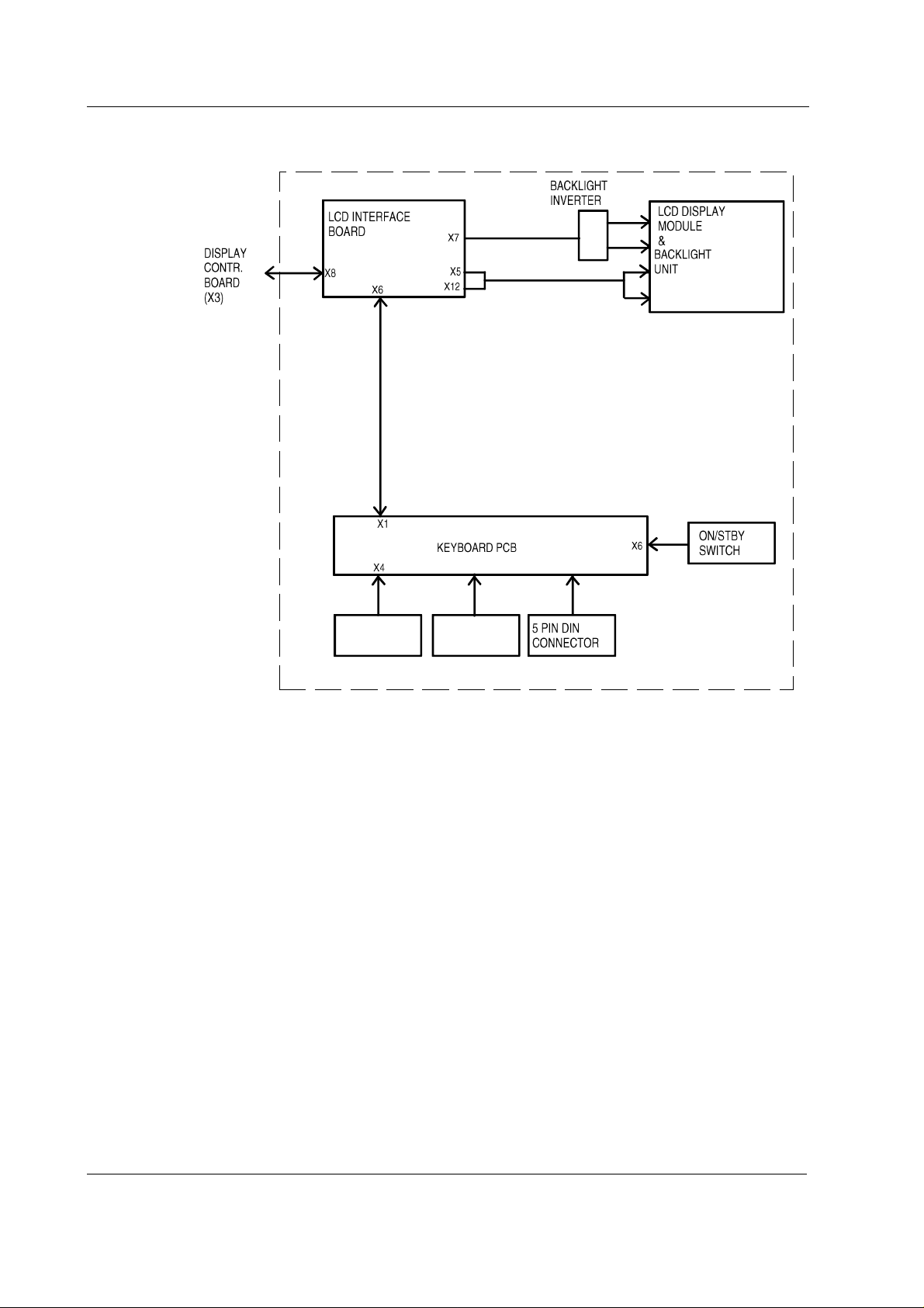
Figure 1 General block diagram, D-LCC10A/C (rev. 01)
2.2.1 LCD interface board
The LCD Interface board is the interface between the display controller board and the LCD display
component. The keyboard is also connected to the Interface board, see figure 1.
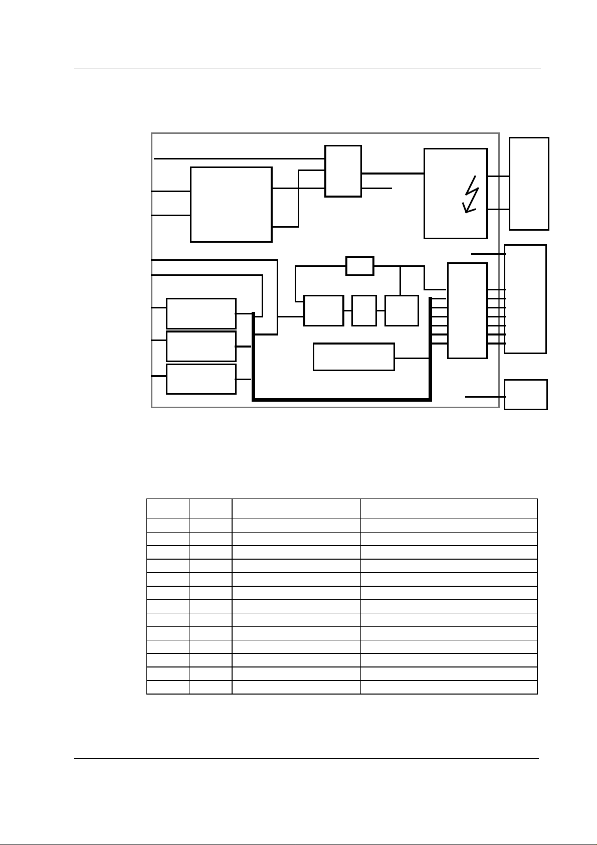
The incoming signal to LCD Interface board is pure analog VGA - RGB with separate horizontal and
vertical synchronisation signals, see figure 2. The display element uses digital RGB-signals,
HSYNC, VSYNC, DOTCLK and a display timing signal DTMG. The DTMG signal indicates that the
digital RGB-signals are active.
The functions of this board are digitalization of the video signals, regeneration of the DOTCLK and
generation of the DTMG. The backlight driver is also located on the board.
Power supply, D-LCC10A/C
The DC/DC power supply is an isolated discontinuous mode flyback switcher. It has a current
mode PWM circuit and a separate FET switch on the primary side. The transformer has two
secondary windings, one for 5V and another for 12V. On the secondary side (5V), there is a
separate chip on the feedback path to drive the optoisolator.
8
Document No. 8001004-1
Page 15
Backlight unit, D-LCC10A/C
The backlight unit consists of two changeable tubes fed by separate inverter board.
Displays and Controller Boards
ON/STBY
VBUS
GND
HSYNC
VSYNC
R
Video
Amplifier
G
Video
Amplifier
B
Video
Amplifier
POWER
+5V
32V
+12V
ON/
STBY
control
/792
Phase
detector
Logic to generate
DTMG -signal
filter
12VINV
5VKb
VCOLP
DTMG
Figure 2 LCD interface board block diagram, D-LCC10A/C
Backlight
inverter
Digital
BUS
buffer
+5V
5VKb
CCFL
Backlight
LCD
Display
Element
Keyboard
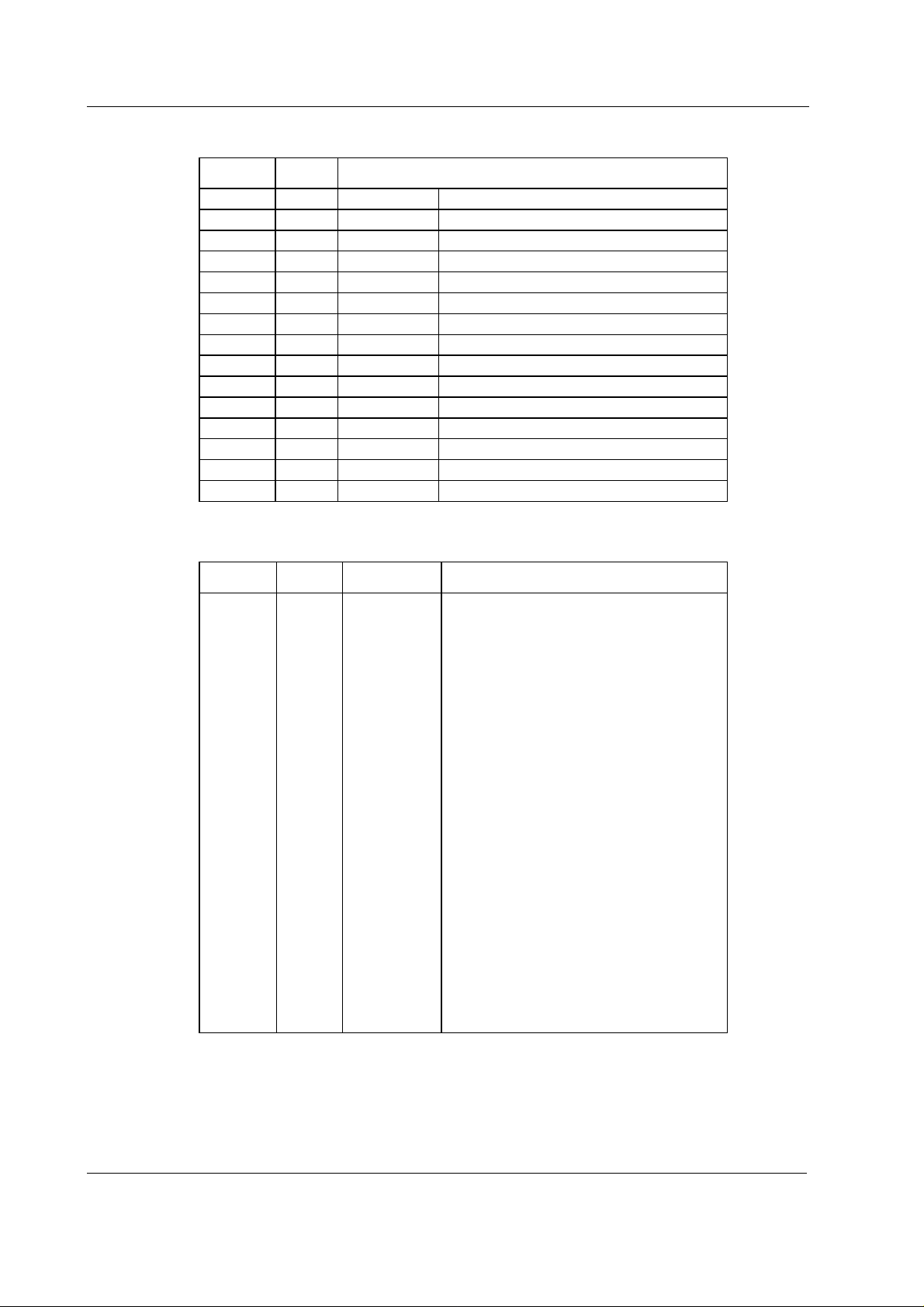
2.3 External connector configurations
Main connector on LCD display, D-LCC10A/W
Pin No I/O Signal Notes
1 I Dirty Ground
2I Intensity
3 I Hsync2 horiz. Deflect
4 I Vsync2 vert. Deflect
5 I Contrast
6 I +32 Vdd
7 I GND
8 O RXDD RS232 from keyboard
9 I TXDD RS232 to keyboard
10 I ON/STBY active GND
A1 I BLUE GND & BLUE VIDEO 2
A2 I GREEN GND & GREEN VIDEO2
A3 I RED GND & RED VIDEO2
Document No. 8001004-1
9
Page 16
S/5 Anesthesia Monitor and S/5 Critical Care Monitor
Connector on D-LCC15 and D-VMC15, on D-VNC15 and on D-VHC17
Pin No Signal
1<-RV Red
2 <- GV Green
3<-BV Blue
4 -> ID2 Monitor Identification (LG)
5<-ST Self test
6 <- RG Ground (red)
7 <- GG Griund (green)
8 <- BG Ground (blue)
9-- 10 - LG Ground (logic)
11 -> ID0 Monitor Identification (LG)
12 -> ID1 Monitor Identification (N.C.)
13 <- HS Horizontal sync.
14 <- VS Vertical sync.
15 - - Not used
Connector at the end of interface cable (Display Controller Board side)
Pin No I/O Signal Note
1
2
3
4
5
6
7
8
9
10
11
12
13
14
15
16
17
18
19
20
21
22
23
24
25
26
O
O
O
O
O
O
O
O
O
O
O
O
O
I
O
O
O
RED VIDEO2
GREEN VIDEO2
BLUE VIDEO2
BLANK
GND
Hsync2
Vsync2
RED GND
GREEN GND
BLUE GND
GND
DCLK GND
not connected
ON/STBY
Dirty GND
Dirty GND
RXDD RS232
TXDD RS232
not connected
not connected
not connected
not connected
+32 Vdd
+32 Vdd
not used
chassis
horiz. deflect
vert. deflect
chassis
active GND
from keyboard
to keyboard
10
Document No. 8001004-1
Page 17

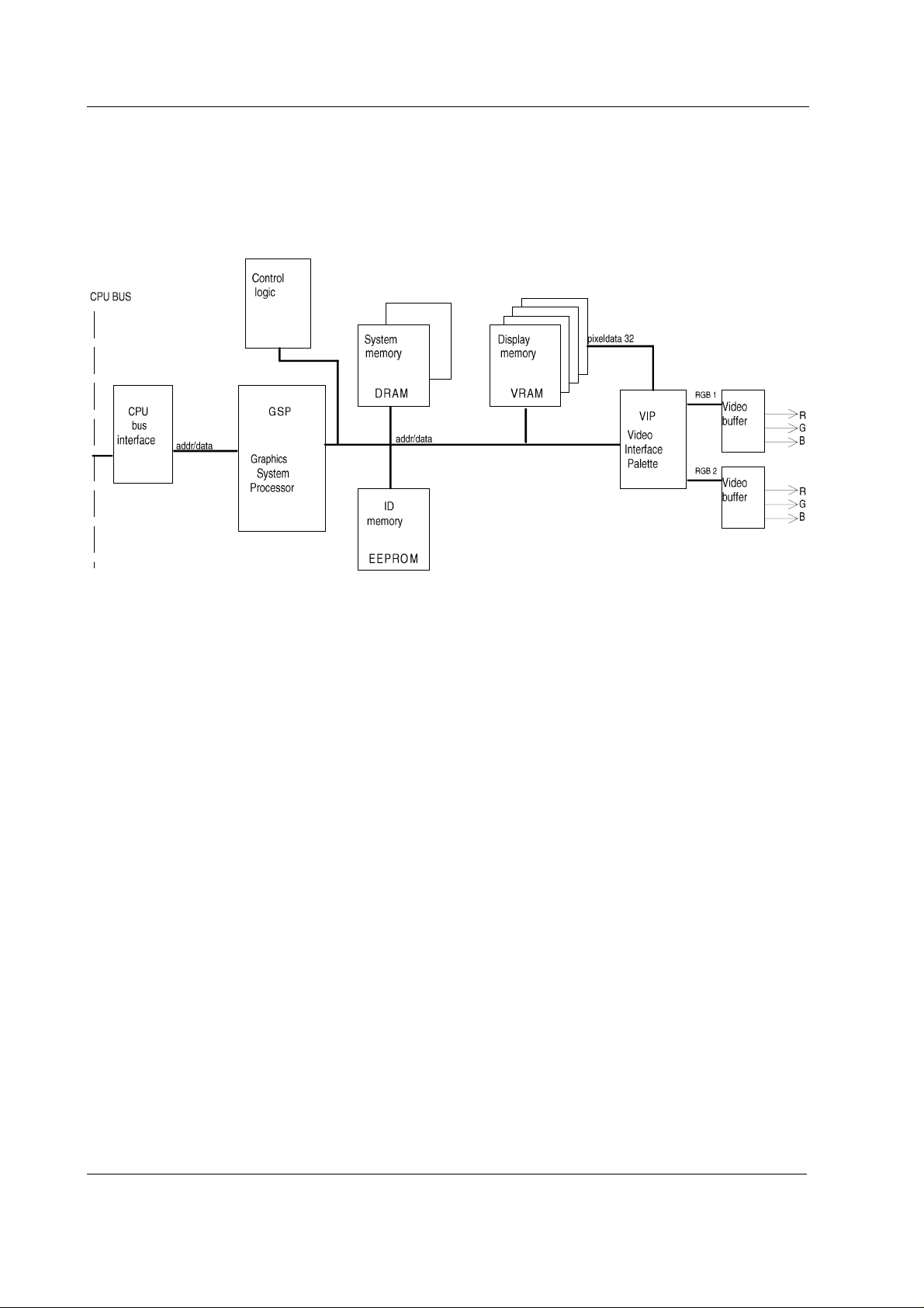
2.4 Display Controller Board, B-DISP
B-DISP board is connected to the CPU Mother board. The processor on the CPU board transmits
program through the CPU bus to B-DISP board.
B-DISP board includes the functions of both B-DHIGH and B-DVGA boards. Thus, B-DISP board
supports both high resolution and VGA resolution. The resolution is automatically selected based
on monitor ID codes. The resolution is set to 640x480 if a VGA resolution display is used, otherwise
the resolution is set to 1984x512.
NOTE: S-ANE97/98/99, S-ICU97/98/99 and S(L)-ARK97/98/99 softwares support B-DISP, BDHIGH and B-DVGA boards. If, however, B-DISP board is used to drive D-VHC14 display, a small
part of the resulting picture will be clipped.
System memory
The system memory contains the GSP software code. The memory consists of two 256k x16
memory banks.
Frame memory
The frame memory contains digital display data. The size of the memory is 1 MB making 1984 x
512 display resolution with 256 colors possible. The memory consists of four 256k x 8 VRAM
memory circuits.
Displays and Controller Boards
Video interface palette
The video interface palette reads the digital display data from the frame memory and converts the
data into analog RGB-signals. The synchronization signals for the conversion are generated by the
GSP.
The video interface palette is clocked by two pixel clocks. A 25 MHz clock is selected for VGA
resolution and a 40 MHz clock is selected for high resolution. The 40 MHz clock is internally
converted into a 80 MHz clock.
Graphics System Processor (GSP)
There are four 16-bit registers in the GSP, from which the host-processor reads and to which it
writes data.
Display Controller Resolution
The resolution of the display controller depends on initialization of the GSP's registers and
frequency of the video oscillator.
Reset Signal
Reset signal comes from the power supply unit through the CPU bus.
11
Document No. 8001004-1
Page 18
S/5 Anesthesia Monitor and S/5 Critical Care Monitor
Monitor ID register
The monitor ID register contains a three bit (numeric values 0-7) monitor ID code. The register is
connected to channels 11-13 of the X3 D-connector. If no display is connected to B-DISP board or
if the monitor ID code fails, 111 code is generated by pull-up resistors. If the ID code is 011 or
101, VGA resolution is selected, otherwise high resolution is selected.
Figure 3 Display Controller Board, B-DISP, block diagram
12
Document No. 8001004-1
Page 19
2.4.1 Connectors and signals
15-pin D-connector on Display Controller Board, B-DISP, X2
Pin No I/O Signal Note
1
2
3
4
5
6
7
8
9
10
11
12
13
14
15
O
O
O
O
O
O
O
O
O
O
RED VIDEO 1
GREEN VIDEO 1
BLUE VIDEO 1
MON1ID2
GND
RED GND
GREEN GND
BLUE GND
N/C
SYNC GND
MON1ID0
MON1ID1
HSYNC 1
VSYNC 1
N/C
Displays and Controller Boards
analog
analog
analog
monitor identification
monitor identification
monitor identification
TTL, CMOS
TTL, CMOS
26-pin D-connector on Display Controller Board, B-DISP
Pin No I/O Signal
1
2
3
4
5
6
7
8
9
10
11
12
13
14
15
16
17
18
19
20
21
22
23
24
25
26
O
Red video (analog)
O
Green video (analog)
O
Blue video (analog)
I
MON2ID2
I
MON2ID1
O
Ground
I
MON2ID0
O
Horizontal sync
O
Vertical sync
O
Red ground
O
Green ground
O
Blue ground
O
Ground
O
Ground/Sync ground
O
+5 V
I
ON/STBY
O
Ground
O
Ground
I
RxD RS232
O
TxD RS232
O
Brightness
O
Contrast
O
Audbufout
Not connected
O
+32 Vd
O
+32 Vd
13
Document No. 8001004-1
Page 20

S/5 Anesthesia Monitor and S/5 Critical Care Monitor
3 SERVICE PROCEDURES
3.1 General service information
Field service is limited to replacing faulty circuit boards or mechanical parts. The circuit boards are
then returned to Datex-Ohmeda for repair.
Datex-Ohmeda Technical Services is always available for service advice. Please provide the unit
serial number, full type designation and a detailed description of the fault.
CAUTION The tests and repairs outlined in this section should only be attempted by trained
personnel with the appropriate equipment. Unauthorized service may void warranty
of the unit.
3.1.1 Video Display, D-VMC15
Field service is limited to basic adjustments through the display’s keys an d to replacing
mechanical parts of the display stand.
In case of a display failure contact Datex-Ohmeda Technical Services for a possibility to repair the
display at a local repair company.
The display can always be returned to Datex-Ohmeda for repair.
3.1.2 Video Display, D-VNC15
Field service is limited to basic adjustments through the display’s keys an d to replacing
mechanical parts of the display stand.
In case of a display failure contact Datex-Ohmeda Technical Services for a possibility to repair the
display at a local repair company.
The display can always be returned to Datex-Ohmeda for repair.
3.1.3 Video Display, D-VHC17
Field service is limited to basic adjustments through the display’s keys an d to replacing
mechanical parts of the display stand.
The display should be returned to Datex-Ohmeda for repair.
3.1.4 Video Display, D-VSC21
Field service is limited to basic adjustments through the display’s keys.
The display should be returned to Datex-Ohmeda for repair.
3.1.5 LCD Display, D-LCC10A/W
The backlight tubes (2 pcs) are replaceable.
3.1.6 LCD Display, D-LCC15
The backlight tubes (2 pcs) are replaceable in some models.
14
Document No. 8001004-1
Page 21

3.2 Service check
These instructions include complete procedures for a service check. The service check is
recommended to be performed after any service repair. However, the service check procedures can
also be used for determining possible failures.
The procedures should be performed in ascending order.
The instructions include a check forms (
the procedures.
Appendix A-E
Displays and Controller Boards
) which should be filled in when performing
The mark
the procedure.
The procedures are designed for monitors with S/5 monitor software of revision 01. However, most
of the procedures also apply to monitors, which contain some other monitor software
type/revision.
3.2.1 Video Display, D-VMC15
Tools needed Command Board, Central Unit, B-DISP, parameter modules, keyboard (K-ANEB/K-ICUB)
• Turn the monitor to STBY.
1. Check that the display cover and th e picture tube screen are in tact.
2. Check that the display power cord is locked to the display with a power cord guard.
? in the instructions means that the check form should be signed after performing
?
?
3. Disconnect the display power cord from the power supply unit and check that the connector
pins are clean and straight. Check that the power cord is intact.
Reconnect the power cord properly.
?
4. Disconnect the display video cable from the B-DISP and check that the connector pins are
clean and straight. Check that the video cable is intact. Check that the thumb screws on the
video cable connector are intact.
Reconnect the video cable and lock it properly.
?
5. Turn the monitor on. Check that the power-on indicator LED on the display front panel lights
up.
?
• Prepare the picture for adjustments by pushing the menu key HELP on the Command Board
and removing one of the connected plug-in modules from the Central Unit. Wait until the
message regarding the removed module appears onto the monitor screen.
15
Document No. 8001004-1
Page 22

S/5 Anesthesia Monitor and S/5 Critical Care Monitor
6. Remove the keyboard (K- ANEB or K-ICUB )
7. Contrast and brightness adjustments:
Check that the contrast of the colors is changing with contrast control knob . Leave the
adjustment to a suitable level.
Perform the same steps also for BRIGHTNESS.
?
8. Position adjustments:
Go to MAIN MENU (First push button on the left) and select GEOMETRY and vertical centring
( See function of push button on the screen ).
Check that the vertical centring of the picture is changing with the keys + and - . Leave the
adjustment to a suitable level.
Perform the same steps also for horizontal centring, height and width .
Go back to MAIN MENU
?
9. Color temperature adjustments:
Select COLOR and COLOR TEMPERATURE.
Check that the colors on the screen are changing with the keys + and - . Leave the
adjustment to a suitable level.
Perform the same steps also for RED and BLUE.
?
10. Light sensor.
Select SPECIAL on MAIN MENU. Check that light sensor is ON.
Cover the hole on the right side of the screen with your finger and wait few seconds. Check
that the contrast on the screen change and remove your finger. Check that the contrast on
the screen change back to normal.
16
Document No. 8001004-1
Go back the normal screen.
?
Page 23

Displays and Controller Boards
11. Perform electrical safety check and leakage current test.
?
12. Check that the display functions normally after the performed electrical safety check.
?
13. Clean the picture tube with a clean, soft cloth dampened with suitable cleaning solution.
NOTE: Do not use any abrasives or hard objects to remove stains. Do not polish the screen.
Clean the display cover with a cloth dampened with a mild detergent solvent.
NOTE: Do not use strong solvents (e.g. acetone) or aerosol cleaners for cleaning the cover.
?
• Fill in all necessary documents.
3.2.2 Video Display, D-VNC15
Tools needed Command Board, Central Unit, B-DISP, parameter modules
• Turn the monitor to STBY.
14. Check that the display cover and the picture tube screen are intact.
?
15. Check that the display power cord is locked to the display with a power cord guard.
?
16. Disconnect the display power cord from the power supply unit and check that the connector
pins are clean and straight. Check that the power cord is intact.
Reconnect the power cord properly.
?
17. Disconnect the display video cable from the B-DISP and check that the connector pins are
clean and straight. Check that the video cable is intact. Check that the thumb screws on the
video cable connector are intact.
Reconnect the video cable and lock it properly.
?
18. Turn the monitor on. Check that the power-on indicator LED on the display front panel lights
up.
?
Document No. 8001004-1
17
Page 24

S/5 Anesthesia Monitor and S/5 Critical Care Monitor
• Prepare the picture for adjustments by pushing the menu key HELP on the Command Board
and removing one of the connected plug-in modules from the Central Unit. Wait until the
message regarding the removed module appears onto the monitor screen.
19. Position adjustments:
Select VERT CENTRING with the keys SELECT and ADJUST.
Check that the vertical centring of the picture is changing with the keys ADJUST. Leave the
adjustment to a suitable level.
Perform the same steps also for HOR CENTRING.
?
20. Size adjustments:
Select HEIGHT.
Check that the height of the picture is changing with the keys ADJUST. Leave the adjustment
to a suitable level.
Perform the same steps also for WIDTH.
?
21. Shape adjustments:
Select PINCUSHION.
Check that the shape of the picture is changing with the keys ADJUST. Leave the adjustment
to a suitable level.
Perform the same steps also for TRAPEZOID and ORTHOGONALITY.
?
22. Tilt adjustment:
Select TILT.
Check that tilting of the picture is changing with the keys ADJUST. Leave the adjustment to a
suitable level.
18
Document No. 8001004-1
?
Page 25

Displays and Controller Boards
23. Degaussing:
Select DEGAUSSING with the keys SELECT then push the key ADJUST (+) or (>). Check that
the picture on the screen sways briefly with a subdued sound
NOTE: Degaussing (demagnetisation) takes place automatically when the monitor is turned
on. The efficiency of a single degaussing phase decreases if repeated at intervals shorter
than 15 minutes.
?
24. Color temperature adjustments:
Select COLOR or COLOR TEMPERATURE with the keys SELECT and ADJUST.
Check that the colors on the screen are changing with the keys ADJUST. Leave the
adjustment to a suitable level.
Perform the same steps also for RED, BLUE and GREEN (the last adjustment only in Rev.
00-02 displays).
?
25. Contrast mode selection:
Select CONTRAST MODE.
Check that the contrast mode is turning on and off with the keys ADJUST. Leave the
selection into a suitable mode.
?
26. Perform electrical safety check and leakage current test.
?
27. Check that the display functions normally after the performed electrical safety check.
?
28. Clean the picture tube with a clean, soft cloth dampened with suitable cleaning solution.
NOTE: Do not use any abrasives or hard objects to remove stains. Do not polish the screen.
Clean the display cover with a cloth dampened with a mild detergent solvent.
NOTE: Do not use strong solvents (e.g. acetone) or aerosol cleaners for cleaning the cover.
?
29. Fill in all necessary documents.
Document No. 8001004-1
19
Page 26

S/5 Anesthesia Monitor and S/5 Critical Care Monitor
•
3.2.3 Video Display, D-VHC17
Tools needed Command Board, Central Unit, B-DISP and parameter modules
• Turn the monitor to STBY.
1. Check that the display cover and the picture t ube screen are intact.
?
2. Check that the display power cord is locked to the display and display tray with a power
cord guard.
?
3. Disconnect the mains power cord from the display tray. Check that the pins on the display
tray connector are clean and straight. Check that the power cord is intact.
Leave the power cord disconnected.
?
4. Detach the primary fuse holder from the mains power receptacle. Check that the fuse
compartment, the fuse holder and the fuses are clean and intact. Check also that the fuses
are of the correct rating.
Check also the secondary fuse, the secondary fuse holder and compartment.
Reattach the fuses properly and reconnect the mains power cord.
?
5. Disconnect the display video cable from the B-DISP and check that the connector pins are
clean and straight. Check that the video cable is intact. Check that the thumb screws on the
video cable connector are intact.
Reconnect the video cable and lock it properly.
?
6. Turn the monitor on. Check that the power-on indicator LED on the display front panel lights
up (the display power switch should be in ON-position).
20
Document No. 8001004-1
?
• Prepare the picture for adjustments by pushing the menu key HELP on the Command Board
and removing one of the connected plug-in modules from the Central Unit. Wait until the
message regarding the removed module appears onto the monitor screen.
Page 27

Displays and Controller Boards
7. Contrast and brightness adjustments:
Activate the contrast adjustment by pushing the key ADJUST (-) or ADJUST (+).
NOTE: When the function LED is light up, push the key FUNCTION before adjusting contrast
and brightness.
Check that the contrast of the colors is changing with the keys
ADJUST (-) and ADJUST (+). Leave the adjustment to a suitable level.
Perform the same steps for brightness adjustment with SELECT (-) and SELECT (+) keys.
NOTE: The contrast and brightness adjustments are stored automatically after 15 seconds
from the last change.
?
8. Position adjustments:
Press the key FUNCTION. Select the horizontal position adjustment by pushing the key
SELECT (-/+). Adjust the position by pushing the key ADJUST (-/+). Store the adjustment by
pushing the key STORE.
Adjust the vertical position correspondingly.
?
9. Size adjustments:
Press the key FUNCTION. Select the horizontal size adjustment by pushing the key SELECT (-
/+). Adjust the size by pushing the key ADJUST (-/+). Store the adjustment by pushing the
key STORE.
Adjust the vertical size correspondingly.
?
10. Shape adjustments:
Press the key FUNCTION. Select the pincushion adjustment by pushing the key SELECT (-
/+). Adjust the pincushion by pushing the key ADJUST (-/+). Store the adjustment by
pushing the key STORE.
Adjust the trapezoid correspondingly.
?
21
Document No. 8001004-1
Page 28

S/5 Anesthesia Monitor and S/5 Critical Care Monitor
11. Rotation adjustment:
Press the key FUNCTION. Select the rotation adjustment by pushing the key SELECT (-/+).
Adjust the rotation by pushing the key ADJUST (-/+). Store the adjustment by pushing the
key STORE.
?
12. Degaussing:
Press the key DEGAUSS. Check that the picture on the screen sways briefly with a subdued
sound
NOTE: Degaussing (demagnetisation) takes place automatically when the monitor is turned
on. The efficiency of a single degaussing phase decreases if repeated at intervals shorter
than 10 minutes.
?
13. Color adjustments:
Press the key FUNCTION. Select the color adjustments by pushing the key SELECT (-/+).
Adjust the colors by pushing the key ADJUST (-/+). Store the adjustments by pushing the
key STORE.
?
14. Perform electrical safety check and leakage current test.
?
15. Check that the display functions normally after the performed electrical safety check.
?
16. Clean the picture tube with a cloth dampened with isopropyl alcohol.
NOTE: Do not use water with any kind of detergent for cleaning the picture tube. Do not use
any abrasives or hard objects to remove stains.
Clean the display cover with a cloth dampened with a mild detergent solvent.
NOTE: Do not use strong solvents (e.g. acetone) or aerosol cleaners for cleaning the cover.
22
Document No. 8001004-1
?
• Fill in all necessary documents.
Page 29

3.2.4 Video Display, D-VSC21
Tools needed Command Board, Central Unit and parameter modules
• Turn the monitor to STBY.
1. Check that the display cover and the picture t ube screen are intact.
?
2. Check that all display screws are tightened properly.
?
3. Check that the display power cord is intact.
?
4. Disconnect the display video cable from the Display controller board and check that the
connector pins are clean and straight. Check that the thumb screws on the video cable
connector are intact.
Displays and Controller Boards
Reconnect the video cable and lock it properly.
?
• Make sure that the display has been powerless at least two minutes, then turn the monitor
on.
5. Check that the picture on the display screen is positioned correctly. Readjust the picture
position, if necessary.
?
6. Check that the brightness and contrast are adjusted correctly. Readjust them, if necessary.
?
7. Check that all the colo rs on the screen are clea r.
NOTE: Internal degaussing (demagnetisation) for clearing the colors takes place
automatically when the monitor is turned on.
If necessary, perform extra degaussing using an external degaussing coil.
?
8. Perform electrical safety check and leakage current test.
?
23
Document No. 8001004-1
Page 30

S/5 Anesthesia Monitor and S/5 Critical Care Monitor
9. Check that the display functions normally after the performed electrical safety check.
?
10. Clean the picture tube with a cloth dampened with isopropyl alcohol.
NOTE: Do not use water with any kind of detergent for cleaning the picture tube. Do not use
any abrasives or hard objects to remove stains.
Clean the display cover with a cloth dampened with a mild detergent solvent.
NOTE: Do not use strong solvents (e.g. acetone) or aerosol cleaners for cleaning the cover.
?
• Fill in all necessary documents.
3.2.5 LCD Display, D-LCC10A, Workstation LCD Display, D-LCC10W
Tools needed Central Unit, B-DISP / B-DVGA, M-NE(12)STPR/M-ESTPR/M-ESTP, Anesthesia Keyboard, K-ARK,
K-ARK - D-LCC10 Interface cable (Order code 881154) and screwdriver
1. Disconnect and check the LCD display interface cable:
The monitor side connector:
− the connector pins are clean and straight and at about the same height
− the locking screws are intact
The display side connector:
− the screw(s) on the casing is tightened properly
− the connector pins are clean and intact
− the locking screws/claws are intact
Check also that the cable itself is intact.
Leave the cable disconnected.
?
2. Detach the rear cover by removing the four screws from the corners.
Check internal parts:
− all screws are tightened properly
− all cables are connected properly
− all IC’s that are on sockets are attached properly
24
Document No. 8001004-1
− there are no loose objects inside the display
Reattach the rear cover.
?
Page 31

Displays and Controller Boards
3. Check external parts:
− the outer cover is intact
− the display screen is intact
− the front panel stickers are intact
− the ComWheel cover is intact and is attached properly
− the ON/STBY -switch and its protector are intact and are attached properly
− the anesthesia keyboard connector is clean and intact
− the LCD interface cable connector is clean and intact
− the block screws for the cable are in place and are tightened properly (if installed)
− the block screw threads are intact (if installed)
?
4. Check that the ON/STBY -switch changes its state firmly when switching it back and forth.
Leave the switch into STBY -position.
?
• Turn the monitor to stand-by. Install the M-NE(12)STPR/M-ESTPR/M-ESTP to the Central
Unit.
• Connect and lock the LCD interface cable to the LCD display and to the used B-DISP/B-
DVGA in the monitor.
5. Check that the stand-by LED on the LCD display front panel is lit up (the monitor power cord is
connected to the mains).
?
• Turn the LCD display ON/STBY -switch to ON.
?
6. Wait until normal monitoring screen appears onto the LCD display. Check that the picture on the
LCD display screen is clear and stable. Check also that all the colors are clear.
?
25
Document No. 8001004-1
Page 32

S/5 Anesthesia Monitor and S/5 Critical Care Monitor
7. Enter the service menu:
Monitor Setup
Take down the information regarding LCD display keyboard software.
- Install/Service
(password 16-4-34)
- Service
(password 26-23-8)
?
8. Select the menu KEYBOARD with the ComWheel.
Highlight the text UPPER LED. Check that the red alarm LED is turning on and off on the LCD
display when pressing the ComWheel. Check also the yellow alarm LED by selecting LOWER
LED from the menu.
?
9. Check the LCD display membrane keys.
Press the keys on the LCD display front panel one by one. Check that each key generates a
sound from the loudspeaker and the corresponding text in the menu changes from yellow to
red.
?
10. Check the ComWheel.
Turn the ComWheel clockwise and counterclockwise and check that each step generates a
sound from the loudspeaker and the corresponding values at the bottom of the menu
increase.
Select DUMMY PRESS. Press the ComWheel and check that the press generates a sound
and the corresponding value in the menu increases.
?
• Turn the LCD display ON/STBY -switch to STBY. Connect the Anesthesia Keyboard to the
LCD display side panel connector with the interface cable, order code 881154.
11. Turn the monitor back on and check that the Anesthesia Keyboard functions normally through
the LCD display.
?
12. Perform electrical safety check and leakage current test.
?
13. Check that the LCD display functions normally after the performed electrical safety check.
?
14. Clean the LCD display with suitable detergent.
?
Fill in all necessary documents.
26
Document No. 8001004-1
Page 33

3.2.6 LCD Display, D-LCC15
Tools needed Central Unit, B-DISP, Keyboard, K-ANEB/ K-ICUB and screwdriver
1. Disconnect and check the LCD display interface cable:
The monitor side connector:
− the connector pins are clean and straight and at about the same height
− the locking screws are intact
The display side connector:
− the screw(s) on the casing is tightened properly
− the connector pins are clean and intact
− the locking screws/claws are intact
Check also that the cable itself is intact.
Leave the cable disconnected.
?
Displays and Controller Boards
2. Detach the rear cover by removing the four screws under the gray pads and two small black
screws on the bottom (middle).
Check internal parts:
− all screws are tightened properly
− all cables are connected properly
− all IC’s that are on sockets are attached properly
− there are no loose objects inside the display
Reattach the rear cover.
?
3. Check external parts:
− the outer cover is intact
− the display screen is intact
− the block screws for the cable are in place and are tightened properly (if installed)
− the block screw threads are intact (if installed)
?
• Connect and lock the LCD interface cable to the LCD display and to the used B-DISP in the
monitor. Check that the display power cord is locked to the display.
• Turn the LCD display ON/STBY -switch to ON.
?
Document No. 8001004-1
27
Page 34

S/5 Anesthesia Monitor and S/5 Critical Care Monitor
4. Wait until normal monitoring screen appears onto the LCD display. Check that the picture on
the LCD display screen is clear and stable.
NOTE! Check that display screen use the XGA mode.
Display Setup
- Install/Service
(password 16-4-34)
– Installation
?
5. Contrast and brightness adjustments:
NOTE: The control keys can be unlocked/locked by pressing the -, + and ∨ -keys
simultaneously.
Go to MAIN MENU (press ∧ or ∨- button on right side of front panel of display) and select
BASIC SETTING.
Select CONTRAST and check that the contrast of the colors is changing with the keys
+ and -. Leave the adjustment to a suitable level.
Perform the same steps also for BRIGHTNESS.
?
6.Position adjustments:
Go to MAIN MENU and select POSITION and vertical position (V- POSITON ).
Check that the vertical position of the picture is changing with the keys + and - . Leave the
adjustment to a suitable level.
Perform the same steps also for horizontal position .
Go back to MAIN MENU
?
7. Color temperature adjustments:
Select COLOR TEMP MENU and USER.
Check that the colors on the screen are changing with the keys + and - . Leave the adjustment to a
suitable level.
Go back the normal screen.
?
8. Perform electrical safety check and leakage current test.
?
28
Document No. 8001004-1
Page 35

9. Check that the LCD display functions normally after the performed electrical safety check.
?
10. Clean the LCD display with suitable detergent.
?
• Fill in all necessary documents.
3.3 Disassembly and reassembly
3.3.1 LCD Display, V-LCC10 A/W
Disassemble the LCD Display according to the following procedure. Please refer to the exploded
view of the LCD Display.
NOTE: Wear a static control wrist strap and soft cotton gloves (dust free) when handling the LCD
Display parts. Do not touch connector pins.
1. Place the LCD Display on a flat surface the front side downwards.
Displays and Controller Boards
Rev. 03, 04
2. Remove the screws (4) that are located at the corners of the rear panel.
3. Lift the rear panel gently, disconnect the cable(s) and set the rear panel aside.
In normal circumstances it is very difficult to keep the LCD Display component and the LCD Display
shield free of dust when those are detached from the LCD Display frame. If dust particles remain o n
the LCD Display component and LCD Display shield surfaces, those may impair the quality of
picture on the screen .
In case you need to detach the LCD Display component for repair, if you can provide a dust free
environment, follow the instructions below. Otherwise, you may return the whole LCD Display to be
repaired at Datex-Ohmeda.
NOTE: If the LCD Display unit is broken, handle it carefully to avoid injury (the LCD Display
component and the backlight lamp are made of glass). Wash your hands if you touched liquid
crystal which may flow out from a broken LCD Display component.
NOTE: Do not touch , push or rub the exposed soft polarizer. Keep the polarizer clean. In case of
accidental mishandling see the instructions following this chapter.
1. The Adapter board and its insulation plate can be detached by disconnecting the cable
connectors and removing the screws (4).
2. Remove the screws (8) that are located at the back of the LCD Display unit.
3. The following parts can now be lifted off one by one:
− the Adapter unit
− the LCD Display component with the backlight
− the LCD Display shield
− the EMC cover with the LCD Display gasket
29
Document No. 8001004-1
Page 36

S/5 Anesthesia Monitor and S/5 Critical Care Monitor
4. The Command board PCB can be detached by disconnecting the cable connectors and
removing the screws (3).
Rev. 00, 01, 02
1. The backlight unit as well as the LCD Display component can be detached by removing the
screws (4) at their corners.
2. The Command board PCB can be detached by disconnecting the cable connectors and
removing the screws (2).
3. The Power supply board is attached to the rear panel by four (4) screws.
Reassembly of the LCD Display is made in reversed order. Make sure that all connectors are
connected properly and cables are not pinched between covers.
Replacing the Backlight Tubes, D-LCC10A/W
1. Disconnect the folio cables (2 pcs) by opening connector’s front part in cable direction.
2. Disconnect the other cables from the LCD interface board.
3. Unscrew 5 screws and draw out the lid.
4. Detach the connector of the backlight tube from the inverter board.
5. Unfasten those two screws that holds the backlight tube and draw out it with the clamp.
6. Locate the new backlight tube, fasten the screws, and connect it to the invert board.
7. Attach all the parts, and make sure that the folio cables are connected properly. Make sure
that the folio cables are at the bottom and straight before locking the connector.
Adapter board (892424) jumpers on D-LCC10A/W
The right position for jumper X3 is 2-3.
Position for jumper X13 according to cable lenght:
1-2 0.5...2.5 m
2-3 > 2.5...10.0 m
NOTE: If you change the cable to a long (10 m) or to a short (2.5 m or shorter) one, you may have to
change jumper setting inside the display cabin in order to get a clear picture. Let an authorised
person to do this.
3.3.2 LCD Display, D-LCC15
Replacing the Backlight Tubes
30
Document No. 8001004-1
1. Disconnect the display cables from the Central Unit and lift off the display together with the
display stand.
2. Remove the hole covers and 6 screws from the back corners and bottom line of the display
case. Separate the front panel from the back panel of the monitor .
3. Remove 8 screws attaching the display case to he front display case. Take display case out
of the front cover and place it face down on a nonabrasive clean surface.
Page 37

4. Locate the bulb replacement slots located on the same side as the display buttons. Remove
the copper tape as necessary.
5. Turn the display over and remove the screw fastening the button circuit board to the display
case.
6. Turn the display over and remove the screw fastening the slots ccver to the display case.
7. Carefully free the wires from display case to access the bulb connector. Separate
connector.
8. Locate the screw hole located near the top removal slot on back face of the display case.
Remove the screw hole to free the bulb for replacement.
9. Pull the cable on female side of connector out of the display case and continue pulling until
the bulb is completely removed.
10. Slide the new replacement backlights into slots on the side of display case.
Reassembly of the LCD Display is made in reversed order. Make sure that all connectors are
connected properly and cables are not pinched between covers.
3.3.3 Video Display, D-VMC15
Displays and Controller Boards
1. The display should not be attempted to disassemble.
3.3.4 Video Display, D-VNC15
11. Disconnect the display cables from the Central Unit and lift off the display together with the
display stand.
12. Detach the display by removing the screw from the bottom of the display stand.
13. The display should not be attempted to disassemble.
14. Reassembly is made in reversed order.
3.3.5 Video Display, D-VHC17
1. Disconnect the display signal cable from the Central Unit and the mains power cord from
the display stand.
2. Lift off the display together with the display stand.
3. Detach the display from the display stand by disconnecting the display power cable and
removing the four screws from the bottom of the stand.
4. The display bracket can be detached by removing the screws from the bottom and then
sliding it off.
5. The display should not be attempted to disassemble.
6. Reassembly is made in reversed order.
3.3.6 Video Display, D-VSC21
The display should not be attempted to disassemble.
31
Document No. 8001004-1
Page 38
S/5 Anesthesia Monitor and S/5 Critical Care Monitor
4 TROUBLESHOOTING
4.1 Video Displays, D-VMC15, D-VNC15, D-VHC17, D-VSC21
Problem Indicator on the
Treatment
front panel
Picture screen is blank The indicator on the front
panel is not illuminated
Picture screen is blank The indicator on the front
panel is illuminated
Problem Treatment
Picture has color defects Demagnetize the monitor using the display’s key/menus.
If color defect is repeated without the monitor having been moved, it is possible that the monitor is
influenced by a strong interference field (near to a high power cable, for example). Try to find a better
location for the monitor or the interference source.
Picture is unreadable Turn off the monitor for a moment. If the display remains unclear after the restart, the display may be out of
synchronization. Try to locate the fault by replacing p arts.
Picture is black and white Check that the signal cable’s connector is completely inserted. Turn off the monitor and restart.
‘Power Saver’ or ‘Not
connected’ message on the
screen during an operation.
The video signal is not recognized by the display. Check that the signal cable’s connector is inserted
properly. Turn off the monitor and restart. If the message remains, try to locate the fault by replacing parts.
NOTE: The described messages may appear at a start-up before the monitoring starts!
Check that the power cord is correctly connected to the display and to the
power outlet. Check that the monitor is turned on with the ON/STBY switch.
The display might be in stand-by position.
Check that the signal cable connector is connected. If the connector is
loose, tighten the connector’s screws.
Check the signal cable’s connection pins. If the pins are slightly distorted,
use nose pliers to straighten them.
This is normal and does not require further actions.
32
Document No. 8001004-1
Page 39

Displays and Controller Boards
4.2 LCD Displays, D-LCC10, D-LCC15
Problem Cause Treatment
No image on screen and no backlight No power or loose interface cable. Check LCD - ON/STBY switch position and
interface cable
No image on screen, backlight on Cables may be loose. Display controller
board or LCD Interface board failure
Vertical stripes on right side of screen
continuously
Only small portion of CRT screen is
displayed on LCD display in zoomed-up
form
Unstable image +5 V unstable. Loose cable. Jumpers in
Backlight flickering or dim Backlight connector failure or lamp/LCD
Jumpers in Display controller board not
positioned correctly
LCD Display defined as High Resolution
Display with the B-DVGA and S-___94.
Display controller board not positioned
correctly or board failure. LCD Interface
board failure
Interface board failure
Check the items. Replace the board(s) if
necessary
Check the jumpers. See Installation section
from Part I for details.
Use menu (Monitor setup-Install/ServiceScreen 2 setup) to change into VGA.
Check cable connections. Check the jumpers.
Check the board(s) and replace if necessary
Check the connector. Check the lamp/ LCD
Interface board failure. If faulty lamp, replace
the whole LCD unit. See chapter 3.3.
4.3 Display Controller Boards, B-DISP
Problem Cause Treatment
No image on the screen No power
Cable or display board loose
Board or display faulty
Regular stripes on the picture Faulty Display controller board Replace the board.
Part of the screen has wrong colors Triac board failure Replace triac board, see Part II/8-Module Frame,
Picture disfigured. Outer magnetic field Turn the monitor off, wait 10 minutes and turn the
Check power on
Check cable and board connections
Try with another board and/or display
F-CU8/Power supply.
monitor on again in order to demagnetize the
screen.
33
Document No. 8001004-1
Page 40

S/5 Anesthesia Monitor and S/5 Critical Care Monitor
5 SERVICE MENU
1. Press the Monitor Setup key.
2. Select
3. Select
Install/Service
Service
(password 26-23-8)
(password 16-4-34).
- Keyboard
.
34
Document No. 8001004-1
Page 41

5.1 Keyboard menu
The service menu for testing the command board functions and for setting the K-ARK and
K-ICU types.
Displays and Controller Boards
Upper Led
is highlighted, the upper alarm LED can be turned on and off by pressing the ComWheel.
Lower Led
text is highlighted, the lower alarm LED can be turned on and off by pressing the
ComWheel.
Dummy Press
ComWheel create a sound from the loudspeaker and the corresponding number on the
service data field increase.
Service Data
Message count counts the number of messages that are sent out to the main CPU board.
Leds upper and lower indicate the states of the alarm LEDs on the command board.
Direct action keys texts are indications to the command board membrane keys. When a
key on the command board is pressed, the corresponding text in the menu changes its
colour.
Control wheel, Press counts the ComWheel pressings.
Control wheel, Clockwise and Counterclockwise the ComWheel turnings.
Since shows the date and the time of the last run time reset.
is for testing the upper alarm LED (red) on the command board. When the text
is for testing the lower alarm LED (yellow) on the command board. When the
is for testing the ComWheel. When the text is highlighted, pressing of the
35
Document No. 8001004-1
Page 42

S/5 Anesthesia Monitor and S/5 Critical Care Monitor
5.1.1 Keyboard Log
All the keyboard presses and the commands given by the ComWheel are recorded in the Keyboard Log.
The keyboard log is saved in the permanent memory of the monitor.
The length of the log is 1150 events. The log is FIFO type.
5.1.2 Keyboard Type
Store Mask
The selected language determines the outcome of the lower keypad.
Store Type
NOTE: The settings should be checked if the controller board is replaced. If settings are changed,
the new settings will not be valid until the next start-up.
A selection for setting the anaesthesia keyboard’s language.
is for setting the keyboard’s type;
COM = Command Board
ARK = Anaesthesia Keyboard
AIC = Information Center Keyboard
36
Document No. 8001004-1
Page 43

Displays and Controller Boards
6 SPARE PARTS
NOTE: Only changed part numbers are listed under later revisions. To find the desired part: check
first the list of the revision that corresponds your device. If the part is not listed there, check the
previous revision, etc. until you find the right number.
* this part is recommended for stock
Item numbers refer to the exploded view.
6.1 14” Video Display, D-VHC14
Item Item description Order No.
- Display cover, D-VHC14 (w/o stickers) 902661
- Monitor cable, D-VHC14 *902660
- Display power cord, D-VHC14 (EUR/USA) 545581
- Service Manual for D-VHC14 (Hitachi) 572772
- Display tray 879474
- Display rear plug cover 879475
6.2 15” Video Display, D-VMC15
Item Item description Order No.
- Facia assembly, D-VMC15 8001566
- Cover assembly, D-VMC15 8001567
- Washer tube fixing, D-VMC15 8001568
- Mains cable, D-VMC15 8001569
- Clip retaining IEC inlet, D-VMC15 8001570
- Video lead, D-VMC15 8001571
- Bracket assembly rear unit, D-VMC15 8001572
37
Document No. 8001004-1
Page 44

S/5 Anesthesia Monitor and S/5 Critical Care Monitor
6.3 15” Video Display, D-VNC15
Figure 4 Exploded view, D-VNC14
6.3.1 15” Video Display, D-VNC15 Rev. 00
Item Item description Order No.
- STBY switch cover, D-VNC15 (Rev. 00-02) 889325
- Display tray 889162
1 Locking washer, D-VNC15 (Rev. 00-02) 889164
2 Motion limiter for 889164 889165
3 Cross cylinder head screw M6x16 61775
5 Power cord guard, D-VNC15 (Rev. 00-02) 889704
6 Cross cylinder head screw M3x8 61722
6.3.2 15” Video Display, D-VNC15 Rev. 01
Item Item description Order No.
- STBY switch, D-VNC15 (Rev. 00-02) 51590
6.3.3 15” Video Display, D-VNC15 Rev. 02
Item Item description Order No.
- Blank command board assembly 892426
1)
38
Document No. 8001004-1
Page 45

Displays and Controller Boards
6.3.4 15” Video Display, D-VNC15 Rev. 03
Item Item description Order No.
5 Power cord guard, D-VNC15 (Rev. 03) 893714
- STBY switch cover, D-VNC15 (Rev. 03) 893112
- Bracket for D-VNC15 (Rev. 03) 892800
- Display tray 891811
- Cross cylinder head screw M6x16 61775
- Blank command board assembly 893723
6.4 17” Video Display, D-VHC17
1)
Figure 5 Exlploded view, Video Display, D-VHC17
6.4.1 17” Video Display, D-VHC17 Rev. 00
Item Item description Order No.
- Fuse T3.15A (for 220-240V) *51119
- Fuse 5A slow (for 100-120V) *511382
- Fuse T2.5A *51118
- Blank command board assembly 892426
1 Display tray, D-VHC17 891978
2 Transformer 220-240V 26143
1)
39
Document No. 8001004-1
Page 46

S/5 Anesthesia Monitor and S/5 Critical Care Monitor
2 Transformer 100-120V 26108
3 Display tray cover, D-VHC17 892396
4 Display bracket, D-VHC17 891979
5 Power cord guard, D-VHC17 892791
6 Display power outlet 54027
7 Mains power receptacle 540140
8 Fuse holder 511792
9 Hexagon cylinder head crew M6x25 61923
10 Cross cylinder head screw M3x6 61621
12 Cross cylinder head screw M3x8 61722
13 Cross cylinder head screw M3x12 61736
14 Cross cylinder head screw M6x16 61775
6.4.2 17” Video Display, D-VHC17 Rev. 01, 02
Item Item description Order No.
- Blank command board assembly 893723
* = the part is recommended for stock
1)
Note: The display tray can fitted with a blank command board assembly in case the display is
used as a secondary display. The blank command board assembly does not contain the ON/STBY switch.
1)
6.5 21” Video Display, D-VSC21
6.5.1 21” Video Display, D-VSC21 Rev. 00
No spare parts available.
6.5.2 21” Video Display, D-VSC21 Rev. 01
No spare parts available.
6.5.3 21” Video Display, D-VSC21 Rev. 02
No spare parts available.
40
Document No. 8001004-1
Page 47

6.6 LCD Display, D-LCC10
Displays and Controller Boards
Figure 6 Exploded view, LCD Display, D-LCC10
6.6.1 LCD Display, D-LCC10 Rev. 01
Item Item description Order No.
- External cable 2.5 m (LCD Display to AS/3 AM) (881966) Use 885517
2 Membrane keyboard, AS/3 AM/CM 879373
3 Command board PCB, D-LCC10 (Rev. 01-02) *(883022) Use 894173
4 LCD Module, AS/3 AM/CM 572770
Document No. 8001004-1
41
Page 48

S/5 Anesthesia Monitor and S/5 Critical Care Monitor
5 Backlight unit, AS/3 AM/CM *883929
6 Power supply board, D-LCC10 (Rev. 01-02) *881808
7 ON/STBY switch *879871
8 ON/STBY switch protector 881431
9 ComWheel cover and spring 879191
10 Rotary wheel 879872
11 Internal cable (Power to Keyboard) 881807
12 Internal cable (Power to LCD) 881721
13 Internal cable (Personal Computer) 881826
14 Inverter for backlight unit, AS/3 AM/CM *572776
15 Adapter board for backlight unit, AS/3 AM/CM 883269
6.6.2 LCD Display, D-LCC10 Rev. 02
Item Item description Order No.
- External cable 2.5 m (LCD Display to AS/3 AM) 885517
- External cable 6 m (LCD Display to AS/3 AM) 884976
42
Document No. 8001004-1
Page 49
6.6.3 LCD Display, D-LCC10 Rev. 03
Displays and Controller Boards
Figure 7 Exploded view, LCD Display, D-LCC10 Rev. 03
LCD Display, D-LCC10 Rev. 03
Item Item description Order No.
- Command board software *887874
- Backlight for LCD display 572784 *(572790) Use 894909
- External cable 2.5 m (LCD Display to AS/3 AM) 888525
- External cable 10 m (LCD Display to AS/3 AM) 888643
3 Command board PCB, AS/3 AM/CM *(886821) Use 894173
Document No. 8001004-1
43
Page 50

S/5 Anesthesia Monitor and S/5 Critical Care Monitor
16 LCD display gasket, AS/3 AM/CM 890123
17 LCD display shield, AS/3 AM/CM 572787
18 LCD display unit, complete, AS/3 AM/CM 887737
19 LCD display (contains backlight), AS/3 AM/CM 572784
20 Adapter unit, AS/3 AM/CM 887125
21 Flat cable 71409
22 Adapter board, AS/3 AM/CM *887840
23 Insulation plate 887739
24 Connector board (LCD), AS/3 AM/CM 888220
25 Connector board (frame), D-LCC10 (Rev.03) 888222
26 Rear cover, D-LCC10 (Rev. 03) 889367
6.6.4 LCD Display, D-LCC10 Rev. 04
New front panel stickers , see “FrontPanelStickeforLCDdisplays”
44
Document No. 8001004-1
Page 51
Displays and Controller Boards
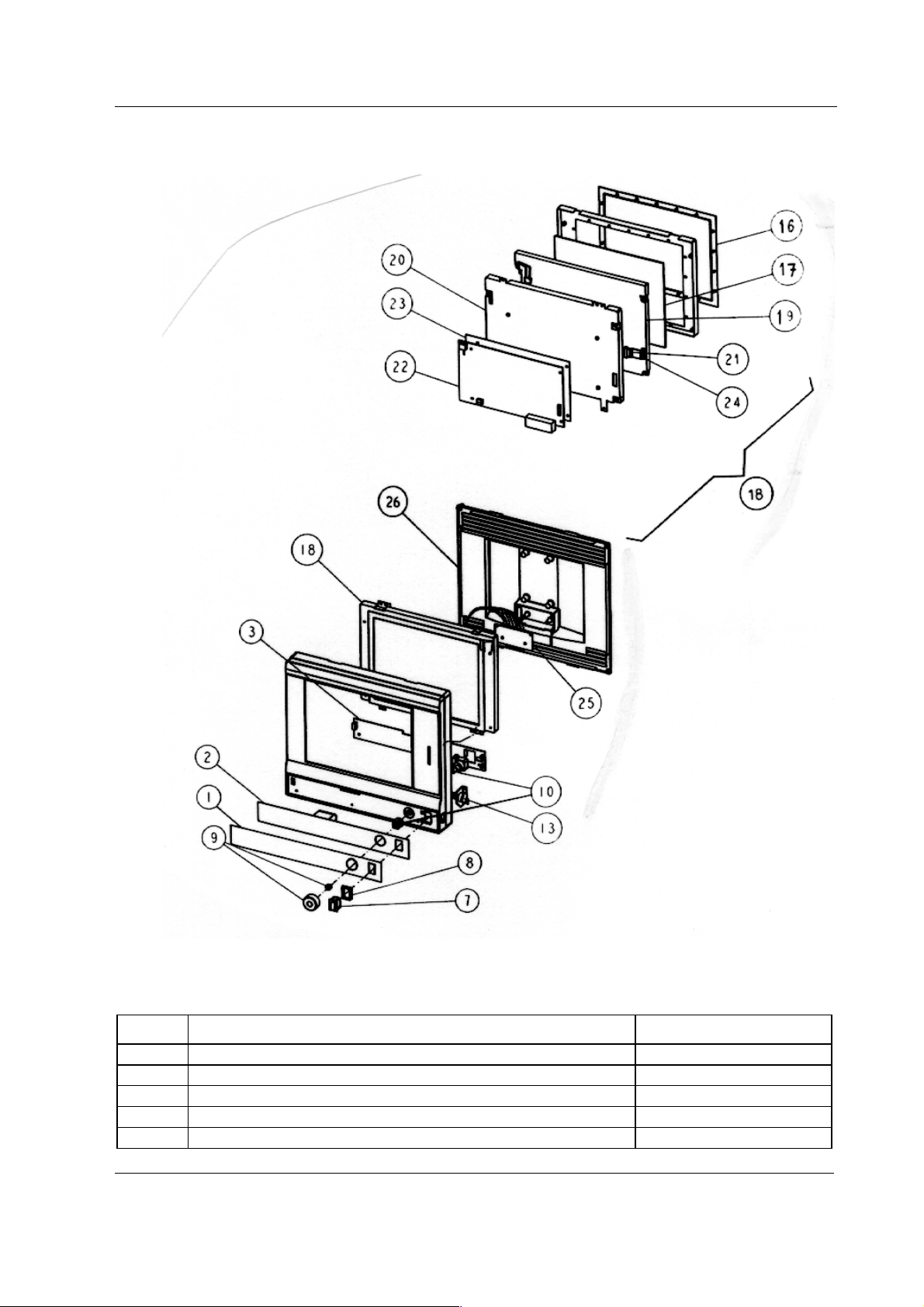
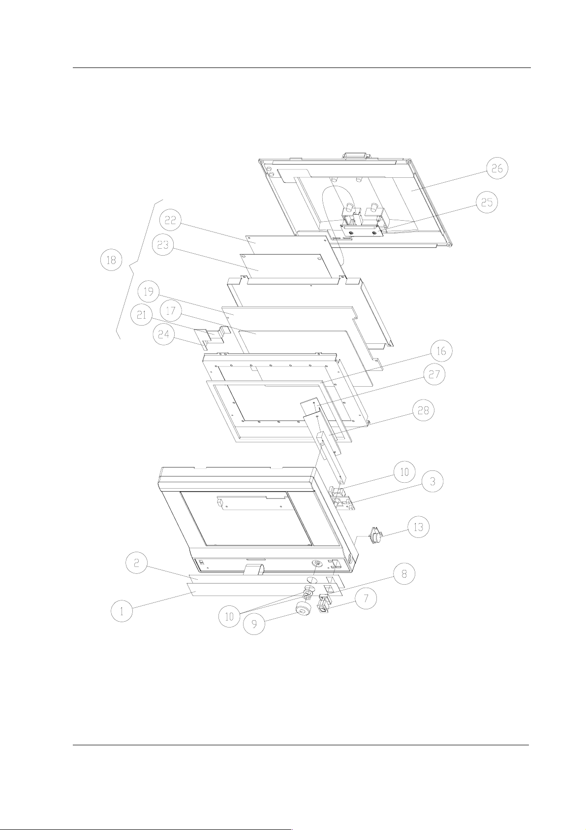
6.6.5 LCD Display, D-LCC10A, LCD Display, D-LCC10C, Workstation LCD Display, D-LCC10W
Rev. 00
Figure 8 Exploded view, LCD Display, D-LCC10A, LCD Display, D-LCC10C, Workstation
LCD Display, D-LCC10W Rev. 00
Document No. 8001004-1
45
Page 52

S/5 Anesthesia Monitor and S/5 Critical Care Monitor
Item Item description Order No.
- Replacement fluorescent lamp for LCD display 572788 *572791
- External cable 2.5 m (LCD Display to AS/3 AM) 888525
- External cable 10 m (LCD Display to AS/3 AM) 888643
2 Membrane keyboard, AS/3 AM/CM 879373
3 Command board PCB, D-LCC10A/C/W *894173
7 ON/STBY switch *879871
8 ON/STBY switch protector 881431
9 ComWheel cover and spring 879191
10 Rotary wheel 879872
13 K-ARK connector with cable 889370
16 LCD display gasket 890123
17 LCD display shield 892677
18 LCD display unit, complete, AS/3 AM/CM 891571
19 LCD display (contains backlight), AS/3 AM/CM 572788
21 Inverter cable 891970
22 Adapter board, AS/3 AM/CM *892424
23 Insulation plate for 892424 891975
24 Connector board, LCD 892421
25 LCD unit cable 893247
26 Rear cover, D-LCC10A, D-LCC10C 892375
26 Rear cover, D-LCC10W 893699
27 Inverter for LCD display 572788 *572789
28 Inverter shield 892677
6.6.6 Front Panel Sticker for LCD displays
Command Board sticker, item No. 1
D-LCC10
Adaptation
(Rev. 01)
Order No.
-23- (Eng) 879479 885878 891663
-26- (Fin) -- 888860 891669
-31- (Jpn) -- 888306 892080
-33- (Ger) 880469 885879 891664
-40- (Spa) -- 886272 891667
-41- (Swe) -- 885946 891670
-42- (Dnk) -- -- 892197
-43- (Fre) 880161 885880 891665
-44- (Dut) -- 886043 891666
-46- (Ita) -- 886751 891668
D-LCC10
(Rev. 02-03)
Order No.
D-LCC10
(Rev. 04)
Order No.
46
Document No. 8001004-1
Page 53
Displays and Controller Boards
D-LCC10A
Adaptation
(Rev. 00)
Order No.
-23- (Eng) 893069 893069 893484
-26- (Fin) 893070 893070 893490
-31- (Jpn)------
-33- (Ger) 893072 893072 893485
-40- (Spa) 893073 893073 893488
-41- (Swe) 893074 893074 893491
-42- (Dnk) 893075 893075 893492
-43- (Fre) 893076 893076 893486
-44- (Dut) 893077 893077 893487
-46- (Ita) 893078 893078 893489
-47- (Nor) 893550 893550 --
D-LCC10W
(Rev. 00)
Order No.
D-LCC10C
(Rev. 00)
Order No.
6.6.7 S/5 Front Panel Sticker for LCD displays
D-LCC10A
Adaptation
(Rev. 01)
Order No.
..01..EN 898328 898328
..01..FI 898335 898335
..01..JA 898339 898339
..01..DE 898329 898329
..01..ES 898332 898332
..01..SV 898336 898336
..01..DA 898338 898338
..01..FR 898330 898330
..01..NL 898331 898331
..01..IT 898333 898333
..01..NO 898333 898337
..01..PT 898334 898334
D-LCC10W
(Rev. 01)
Order No.
Side panel sticker
D-LCC10
Adaptation
(Rev. 01-04)
Order No.
All 881729 891993 891993 891993
D-LCC10A
(Rev. 00)
Order No.
D-LCC10W
(Rev. 00)
Order No.
S/5 Side panel sticker
D-LCC10A
Adaptation
(Rev. 01)
Order No.
All 898312 898312
D-LCC10W
(Rev. 01))
Order No.
Document No. 8001004-1
D-LCC10C
(Rev. 00)
Order No.
47
Page 54
S/5 Anesthesia Monitor and S/5 Critical Care Monitor
6.7 LCD Display, D-LCC15
Item Item description Order No.
- Back light, D-LCC15 8001592
- Video Cable , D-LCC15 8001593
- Power cable, D-LCC15 8001594
-Power, D-LCC15 8001595
6.8 Display Controller Boards, B-DISP, B-DVGA, B-DHIGH
Item Item description Order No.
- Wide rear panel for B-DISP *893872
- Grounding plate 885398
- Block screw for cables 546096
48
Document No. 8001004-1
Page 55

7 EARLIER REVISIONS
For more service information on the earlier revisions, please refer to:
LCD-Display revision 01 Service Manual p/n 882580
LCD-Display revision 02 Service Manual p/n 885930
This manual supports all later revisions.
Displays and Controller Boards
49
Document No. 8001004-1
Page 56

S/5 Anesthesia Monitor and S/5 Critical Care Monitor
50
Document No. 8001004-1
Page 57

Appendices A-G, Displays and Controller Boards
APPENDICES A-G
51
Document No. 8001004-1
Page 58

S/5 Anesthesia Monitor and S/5 Critical Care Monitor
52
Document No. 8001004-1
Page 59

SERVICE CHECK FORM
Video Display, D-VHC14
Customer
Appendices A-G, Displays and Controller Boards
Service
Service engineer Date
OK = Test OK N.A. = Test not applicable Fail = Test Failed
OK N.A. Fail OK N.A. Fail
1. Cover and picture
tube
2. Tray 3. Power cord
3. Video cable
Notes
6. Position adjustments 7. Power cord
Display type
and revision
S/N
2. Cover screws
7. Colors
Notes
9. Electrical safety check 10. Functioning after
electrical safety check
10. Final cleaning
Notes
Used Spare Parts
Signature
A-1(1)
Document No. 8001004-1
Page 60

S/5 Anesthesia Monitor and S/5 Critical Care Monitor
A-2
Document No. 8001004-1
Page 61

SERVICE CHECK FORM Video Display, D-VMC15
Customer
Appendices A-G, Displays and Controller Boards
Service
Service engineer Date
OK = Test OK N.A. = Test not applicable Fail = Test Failed
OK N.A. Fail OK N.A. Fail
1. Cover and picture
tube
2. Power cord 3. Video cable
Notes
5. Power ON LED 6. Contrast and brightness
7. Position and size
adjustments
9. Light sensor
Display type
and revision
S/N
2. Power co rd locking
8. Color adju stments
Notes
14. Electrical safety check 15. Functioning after
electrical safety check
15. Final cleaning
Notes
Used Spare Parts
Signature
B-1(1)
Document No. 8001004-1
Page 62

S/5 Anesthesia Monitor and S/5 Critical Care Monitor
B-2
Document No. 8001004-1
Page 63

SERVICE CHECK FORM Video Display, D-VNC15
Customer
Appendices A-G, Displays and Controller Boards
Service
Service engineer Date
OK = Test OK N.A. = Test not applicable Fail = Test Failed
OK N.A. Fail OK N.A. Fail
3. Cover and picture
tube
4. Power cord 9. Video cable
Notes
10. Power ON LED 11. Contrast and brightness
12. Position adjustments 13. Size adjustments
Display type
and revision
S/N
4. Power co rd locking
14. Shape adjustments 6. Tilt adjustments
15. Degaussing 7. Color adju stments
16. Contrast mode
Notes
16. Electrical safety check 16. Functioning after
electrical safety check
17. Final cleaning
Notes
Used Spare Parts
Signature
C-1(1)
Document No. 8001004-1
Page 64

S/5 Anesthesia Monitor and S/5 Critical Care Monitor
C-2
Document No. 8001004-1
Page 65
SERVICE CHECK FORM Video Display, D-VNC17
Customer
Appendices A-G, Displays and Controller Boards
Service
Service engineer Date
OK = Test OK N.A. = Test not applicable Fail = Test Failed
OK N.A. Fail OK N.A. Fail
1. Cover and picture
tube
2. Power cord connector 3. Fuses and fuse holders
3. Video cable
Notes
6. Power ON LED 7. Contrast and brightness
7. Position adjustments 8. Size adjustments
Display type
and revision
S/N
2. Power co rd locking
8. Shape adjustments 9. Rotation adjustment
9. Degaussing 10. Color adjustments
Notes
14. Electrical safety check 15. Functioning after
electrical safety check
15. Final cleaning
Notes
Used Spare Parts
Signature
D-1(1)
Document No. 8001004-1
Page 66

S/5 Anesthesia Monitor and S/5 Critical Care Monitor
D-2
Document No. 8001004-1
Page 67

SERVICE CHECK FORM Video Display, D-VSC21
Customer
Appendices A-G, Displays and Controller Boards
Service
Service engineer Date
OK = Test OK N.A. = Test not applicable Fail = Test Failed
OK N.A. Fail OK N.A. Fail
1. Cover and picture
tube
2. Power cord 3. Video cable
Notes
5. Position adjustments 6. Brightness and contrast
6. Colors
Display type
and revision
S/N
2. Screws
Notes
8. Electrical safety check 9. Functioning after
electrical safety check
9. Final cleaning
Notes
Used Spare Parts
Signature
E-1(1)
Document No. 8001004-1
Page 68

S/5 Anesthesia Monitor and S/5 Critical Care Monitor
E-2
Document No. 8001004-1
Page 69

APPENDICES, Service check form, LCD Displays
SERVICE CHECK FORM LCD Display, D-LCC10A, LCD Display, D-LCC10C, Workstation LCD Display, D-LCC10W
Customer
Service
Service engineer Date
OK = Test OK N.A. = Test not applicable Fail = Test Failed
OK N.A. Fail OK N.A. Fail
1. Cable 2. Internal parts
3. External parts 4. ON/STBY -switch
Notes
5. Stand by -LED 6. LCD display picture
6. Keyboard software
7. Alarm LEDs 7. Membrane keys
KB
Display type
and revision
S/N
8. ComWheel 8. Anesthesia keyboard
interface
Notes
12. Electrical safety check 13. Functioning after
electrical safety check
13. Final cleaning
Notes
Used Spare Parts
Signature
F-1(1)
Document No. 8001004-1
Page 70

S/5 Anesthesia Monitor and S/5 Critical Care Monitor
F--2
Document No. 8001004-1
Page 71

SERVICE CHECK FORM LCD Display, D-LCC15
Customer
APPENDICES, Service check form, LCD Displays
Service
Service engineer Date
OK = Test OK N.A. = Test not applicable Fail = Test Failed
OK N.A. Fail OK N.A. Fail
1. Cable 2. Internal parts
3. External parts 3. ON/STBY- switch and
Notes
4. Display mode 5. Brightness and contrast
6. Position adjustmenst 7. Colors
Display type
and revision
S/N
standby LED
Notes
8. Electrical safety check 9. Functioning after
electrical safety check
10. Final cleaning
Notes
Used Spare Parts
Signature
G-1(1)
Document No. 8001004-1
Page 72

S/5 Anesthesia Monitor and S/5 Critical Care Monitor
G--2
Document No. 8001004-1
 Loading...