

Page 1
S/5
Datex-Ohmeda Pressure Modules
TM
Pressure Temp Module, M-PT (Rev. 02)
S/5
TM
Pressure Module, M-P (Rev. 04)
Technical Reference Manual Slot
Datex-Ohmeda Inc.
3030 Ohmeda Drive
53707–7550 MADISON, WIS
USA
Tel. +1-608-221 1551, Fax +1-608-222 9147
www.us.datex-ohmeda.com
All specifications are subject to change without notice.
Document No. 800 1013-1
June 2001
Datex-Ohmeda Division,
Instrumentarium Corp.
P.O. Box 900, FIN-00031
DATEX-OHMEDA, FINLAND
Tel. +358 10 394 11 Fax +358 9 146 3310
www.datex-ohmeda.com
Instrumentarium Corp. All rights reserved.
Page 2

Page 3

Table of contents
TABLE OF CONTENTS
Pressure Module, M-P, Pressure Temp Module, M-PT
TABLE OF CONTENTS i
TABLE OF FIGURES ii
Introduction 1
1 Specifications 2
1.1 General specifications ..............................................................................................................................2
1.2 Typical performance .................................................................................................................................2
1.2.1 InvBP...............................................................................................................................................2
1.2.2 Temperature.....................................................................................................................................2
1.2.3 Signal output ...................................................................................................................................2
1.3 Technical specifications............................................................................................................................3
1.3.1 InvBP...............................................................................................................................................3
1.3.2 Temperature.....................................................................................................................................3
1.3.3 Signal output ...................................................................................................................................3
2 Functional Description 4
2.1 Measurement principle .............................................................................................................................4
2.1.1 Invasive blood pressure ....................................................................................................................4
2.1.2 Temperature.....................................................................................................................................4
2.2 Main components.....................................................................................................................................4
2.2.1 PT board ..........................................................................................................................................6
2.3 Connectors and signals...........................................................................................................................10
2.3.1 Module bus connector....................................................................................................................10
2.3.2 Front panel connectors...................................................................................................................11
2.3.3 Other connectors............................................................................................................................11
3 Service Procedures 13
3.1 General service information.....................................................................................................................13
3.2 Service check .........................................................................................................................................13
3.2.1 Recommended tools ......................................................................................................................13
3.3 Disassembly and reassembly..................................................................................................................18
3.4 Adjustments and calibrations..................................................................................................................19
3.4.1 Invasive pressure calibration...........................................................................................................19
3.4.2 Temperature calibration..................................................................................................................19
4 Troubleshooting 21
4.1 Troubleshooting chart .............................................................................................................................21
4.1.1 Invasive blood pressure ..................................................................................................................21
4.1.2 Temperature...................................................................................................................................22
Troubleshooting flowchart ..............................................................................................................................23
5Service Menu 24
5.1 P/PT menu .............................................................................................................................................25
5.2 P/PT calibration menu ............................................................................................................................26
6 Spare Parts 28
i
Document No. 800 1013-1
Page 4

Datex-Ohmeda S/5 monitors
6.1 Spare parts list.......................................................................................................................................28
6.1.1 Pressure Module, M-P, Rev. 00.......................................................................................................28
6.1.2 Pressure Module, M-P, Rev. 01.......................................................................................................29
6.1.3 Pressure Module, M-P, Rev. 02.......................................................................................................29
6.1.4 Pressure Module, M-P, Rev. 03.......................................................................................................29
6.1.5 Pressure Module, M-P, Rev. 04.......................................................................................................29
6.1.6 Pressure Temp Module, M-PT, Rev. 00 ............................................................................................30
6.1.7 Pressure Temp Module, M-PT, Rev. 01 ............................................................................................31
6.1.8 Pressure Temp Module, M-PT, Rev. 02 ............................................................................................31
6.1.9 Front panel stickers for AS/3 modules (square buttons)...................................................................31
6.1.10 Front panel stickers for S/5 modules (round buttons) .................................................................. 31
7 Earlier Revisions 33
APPENDIX A 35
Service check form A-1
TABLE OF FIGURES
Figure 1 Datex-Ohmeda M-PT and M-P Module...................................................................................................1
Figure 2 Front panel of M-P and M-PT Module..................................................................................................... 5
Figure 3 PT board block diagram ........................................................................................................................ 6
Figure 4 Pressure transducer principle of operation.............................................................................................7
Figure 5 Temperature measurement principle..................................................................................................... 8
Figure 6 Serial communication and opto isolation section................................................................................... 8
Figure 7 Module bus connector (X1) .................................................................................................................10
Figure 8 Troubleshooting flowchart...................................................................................................................23
ii
Document No. 8001013-1
Page 5
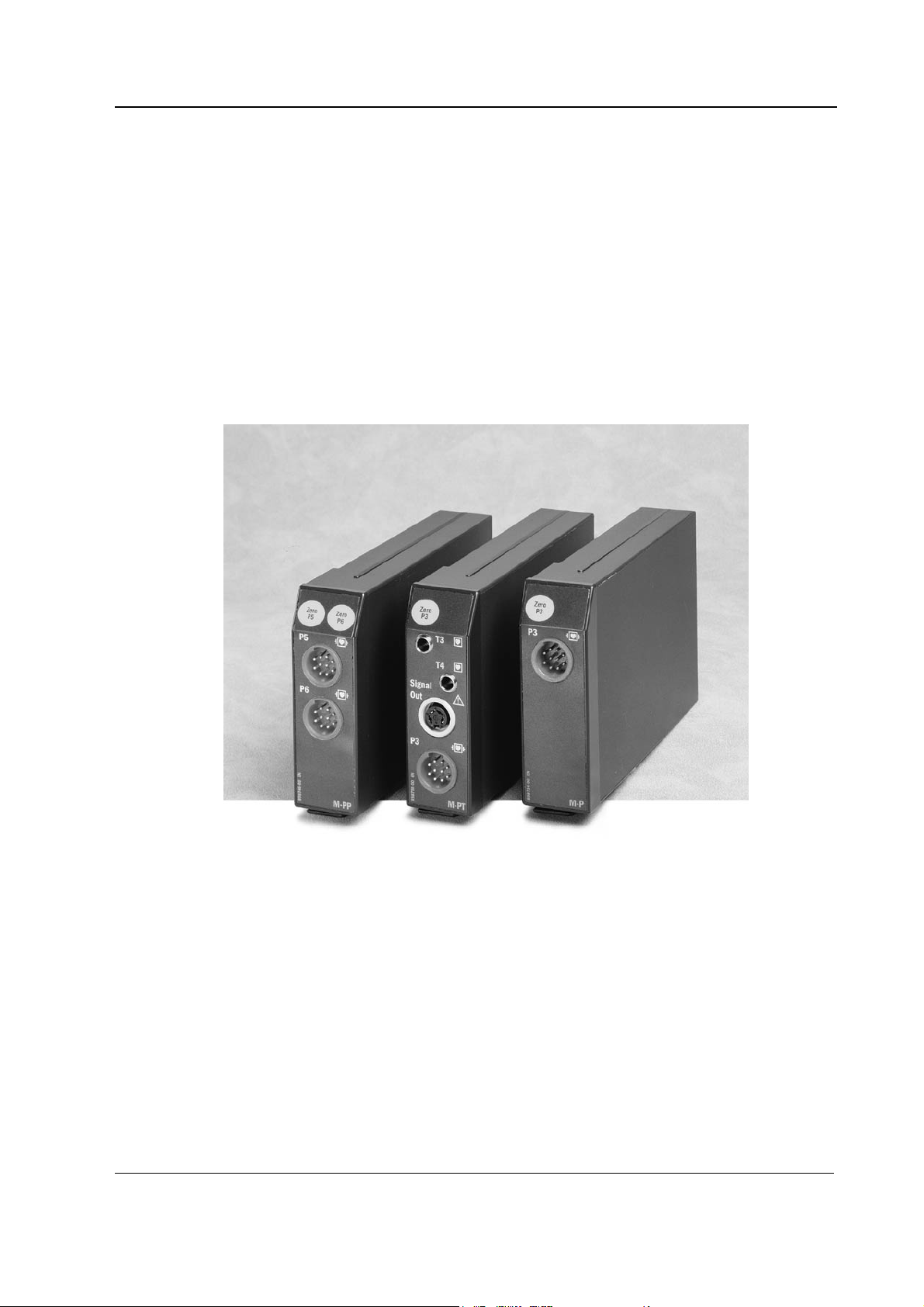
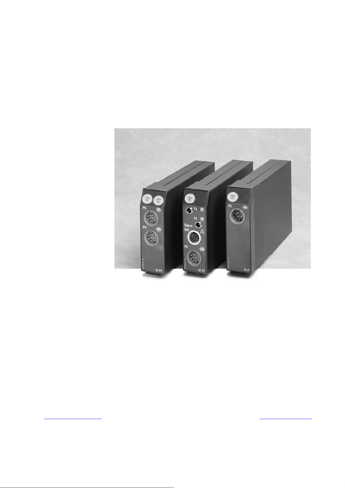
INTRODUCTION
This section provides information for the maintenance and service of the Pressure Module, M-P,
and Pressure Temp Module, M-PT. The M-P and M-PT modules are single width plug-in modules
designed for use with the S/5 monitors. Both modules provide invasive pressure measurement.
Additionally, the M-PT-module provides temperature measurement. The M-PT module also has a
connector for direct ECG and pressure signal output.
NOTE: Do not use identical modules in the same monitoring system. The modules M-P and M-PT
are considered as identical modules.
Pressure Module, M-P and Pressure Temp Module, M-PT
Figure 1 Datex-Ohmeda M-PT and M-P Module
1
Document No. 800 1013-1
Page 6

Datex-Ohmeda S/5 monitors
1 SPECIFICATIONS
1.1 General specifications
Module size, W × D × H 37 × 180 × 112 mm / 1.5 × 7.1 × 4.4 in
Module weight 0.35 kg / 0.8 lbs
Power consumption Approximately 3.5 W
1.2 Typical performance
1.2.1 InvBP
Measurement range -40...+320 mmHg
Accuracy ±5 % or ±2 mmHg, whichever is greater
Zero adjustment range ±150 mmHg
Calibration range ±20 %
Scales Upper limit is adjustable between 10 and 300 mmHg in steps of
Sweep speed 12.5, 25, 50 mm/s
10. Lower limit is 10 % of selected upper limit below zero.
DIGITAL DISPLAY
Range -40...+320 mmHg
Resolution ±1 mmHg
WAVEFORM DISPLAY
Range -30...+300 mmHg
HEART RATE FROM ARTERIAL PRESSURE
Measurement range 30...250 bpm
Resolution 1 bpm
Accuracy ±5 bpm or ±5 %, whichever is greater
1.2.2 Temperature
Measurement range 10...45 °C (50...113 °F)
Display resolution 0.1 °C (0.1 °F)
Temperature test Automatic (every 10 min.)
YSI 400 probe compatible
1.2.3 Signal output
ECG out 1 V/mV
Pressure P3 out 1 V/100 mmHg, (0...300 mmHg)
2
Document No. 8001013-1
Page 7

1.3 Technical specifications
1.3.1 InvBP
Accuracy ±5 % or ±2 mmHg, whichever is greater
Transducer and input sensitivity 5 µV/V/mmHg, 5 VDC, 20 mA max current
Nonlinearity <1 %, 0 to 200 mmHg
Filter 0...4 - 22 Hz adjustable
Zero set accuracy ±1 mmHg
Calibration resolution ±1 mmHg
Zero time less than 15 sec
Protection against electrical shock Type CF defibrillation proof
DIGITAL DISPLAY AVERAGING
Art and P1 digital displays are averaged over 5 seconds and updated at 5 seconds intervals. All
other pressures have respiration artifact rejection.
NOTE: The accuracy of the measurement may be different from that specified, depending on the
transducer/probe being used. Please check the transducer/probe specification.
Pressure Module, M-P and Pressure Temp Module, M-PT
<2 %, -40 to 0 and 200 to 320 mmHg
1.3.2 Temperature
Measurement accuracy ±0.1 °C (25.0...45.0 °C)
Protection against electrical shock Type CF
NOTE: The accuracy of the measurement may be different from the specified, depending on
transducer/probe used. Please check the transducer/probe specification.
1.3.3 Signal output
Max. delay: ECG1 15 ms
Pressure offset error max. 10 mmHg
±0.2 °C (10.0...24.9 °C)
Pressure P3 25 ms (0...300 mmHg)
Document No. 800 1013-1
3
Page 8

Datex-Ohmeda S/5 monitors
2 FUNCTIONAL DESCRIPTION
2.1 Measurement principle
2.1.1 Invasive blood pressure
To measure invasive blood pressure, a catheter is inserted into an artery or vein. The invasive
pressure setup, consisting of connecting tubing, pressure transducer, an intravenous bag of normal
saline all connected together by stopcocks, is attached to the catheter. The transducer is placed at
the same level with the heart, and is electrically zeroed.
The transducer is a piezo-resistive device that converts the pressure signal to a voltage. The monitor
interprets the voltage signal so that pressure data and pressure waveforms can be displayed.
2.1.2 Temperature
The temperature is measured by a probe whose resistance varies when the temperature changes,
called Negative Temperature Coefficient (NTC) resistor.
The resistance can be measured by two complementary methods:
• Applying a constant voltage across the resistor and measuring the current that flows through
it.
• Applying a constant current to flow through the resistor and measuring the voltage that is
generated across it.
In S/5 module the two methods are combined in a form of a voltage divider. The NTC-resistor is
connected in series with a normal resistor and a constant voltage is applied across them. The
temperature dependent voltage can be detected at the junction of the resistors, thus producing the
temperature signal from the patient. The signal is amplified by analog amplifiers and further
processed by digital electronics.
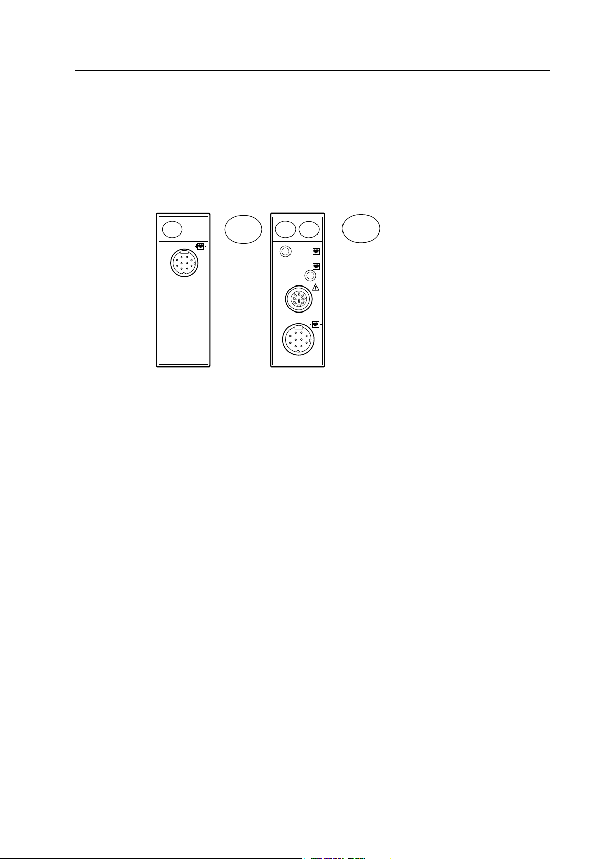
2.2 Main components
The M-PT module consists of the following main parts:
• PT board
• Two connectors for YSI 400 series temperature probes; temperature channels T3 and T4.
• Nicolay-type connector for an invasive blood pressure sensor; invasive blood pressure
channel P3.
• Key for pressure zeroing.
4
Document No. 8001013-1
• DIN-type connector for two direct ECG output signals and pressure 3.
NOTE: These output-signals are non-floating
The M-P module consists of the following main parts:
• PT board
• Nicolay-type connector for an invasive blood pressure sensor; invasive blood pressure
channel P3.
Page 9
Pressure Module, M-P and Pressure Temp Module, M-PT
• Key for pressure zeroing.
Communication between the module and the central unit is established through RS485 serial
interface.
The power supply voltages to the module are generated in the power supply section of the
monitor’s Central Unit. All electrical connections between the module and the Central Unit are
established via 25-pin D-type connector on the backside of the module.
Zero
P3
Signal
Out
P3
T3
T4
P3
Zero
P3
Figure 2 Front panel of M-P and M-PT Module
Document No. 800 1013-1
5
Page 10
Datex-Ohmeda S/5 monitors
A
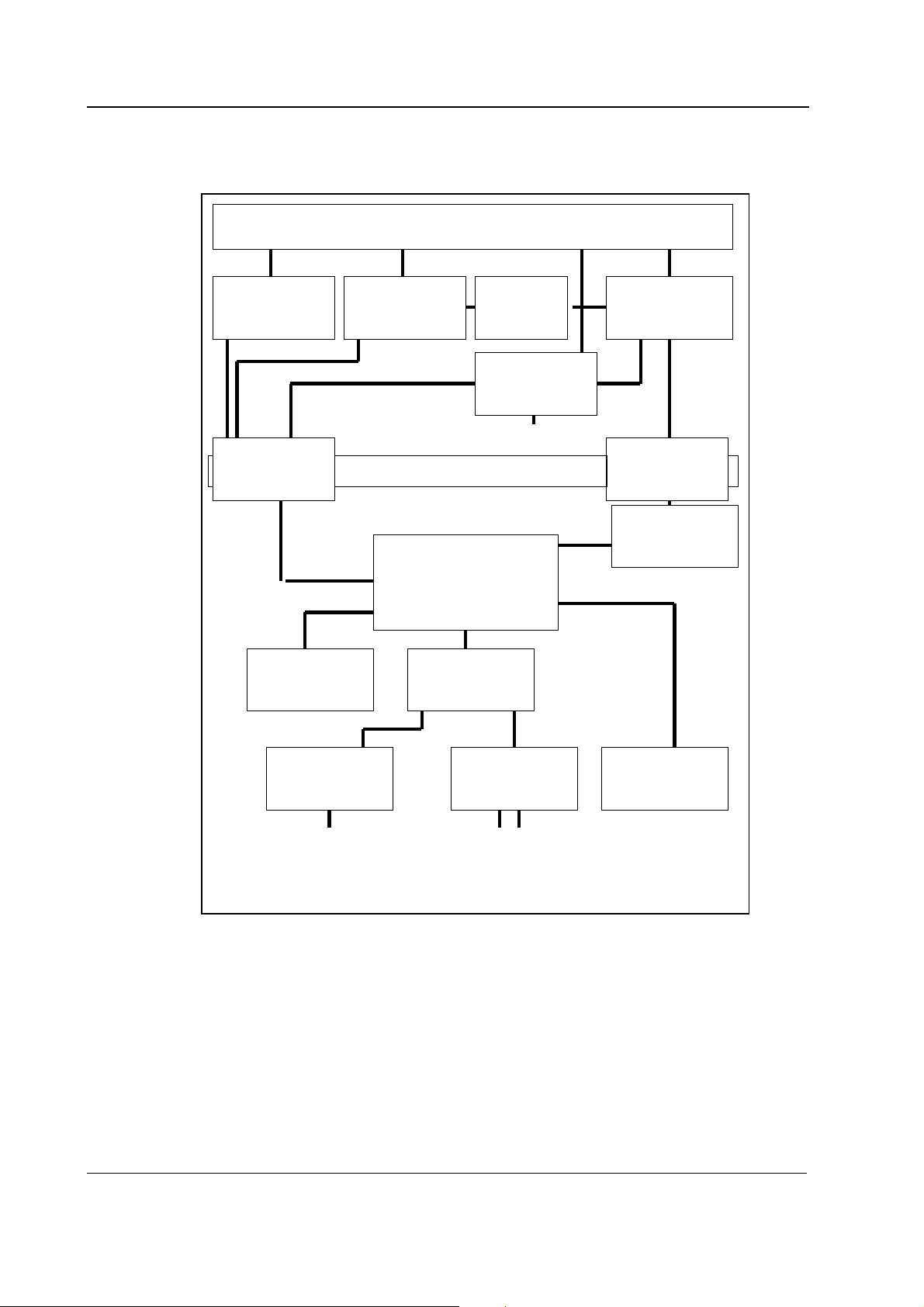
2.2.1 PT board
Module bus connector, D25
RS485 driver
for data
Opto
Isolation
non-volatile
memory
RS485 driver
for module
reset
Patient Isolation
Microprocessor
section
Power-up
reset
ECG OUT
PRESSURE OUT
to output connector
/D converter
Power
,
non-isolated
section
Isolation
transformer
Power,
isolated
section
INV.pressure
measuring
unit
to pressure
sensor
Figure 3 PT board block diagram
ECG and pressure signal prosessing
The PT-module has the Signal Out connector, for output of analog ECG and pressure signals.
The analog ECG-output signals are made by detecting the pulse-width modulated (PWM) ECG
signal of the module bus. The module detects the presence of the pacemaker pulses by following
the ECG module. Every time the pacer pulse has been detected, the microprocessor of the M-PT
module generates a 2.5 ms pacer pulse which is added to the analog ECG signal.
The PRESSURE OUT signal is generated from the P3 invasive pressure signal of the M-PT module.
6
Document No. 8001013-1
Temperature
measuring
unit
to temperature
sensors
Keyboard
Page 11
The P3 signal is transmitted as a pulse width modulated (PWM) signal over the patient isolation.
The analog signal is generated by low-pass filtering the PWM signal.
Microprocessor unit
The microprocessor uses the Intel 80C196KC-16 which includes three A/D converters and a UART.
There are external memories, an 8-bit data bus, a 16 MHz oscillator, an open collector reset, and a
watchdog timer. The internal UART communicates and transfers data between the module and the
CPU board in the monitor.
High speed I/O is used to obtain pulse control sequence necessary for pulse oximetry
measurement. It receives its timing clock from the oscillator.
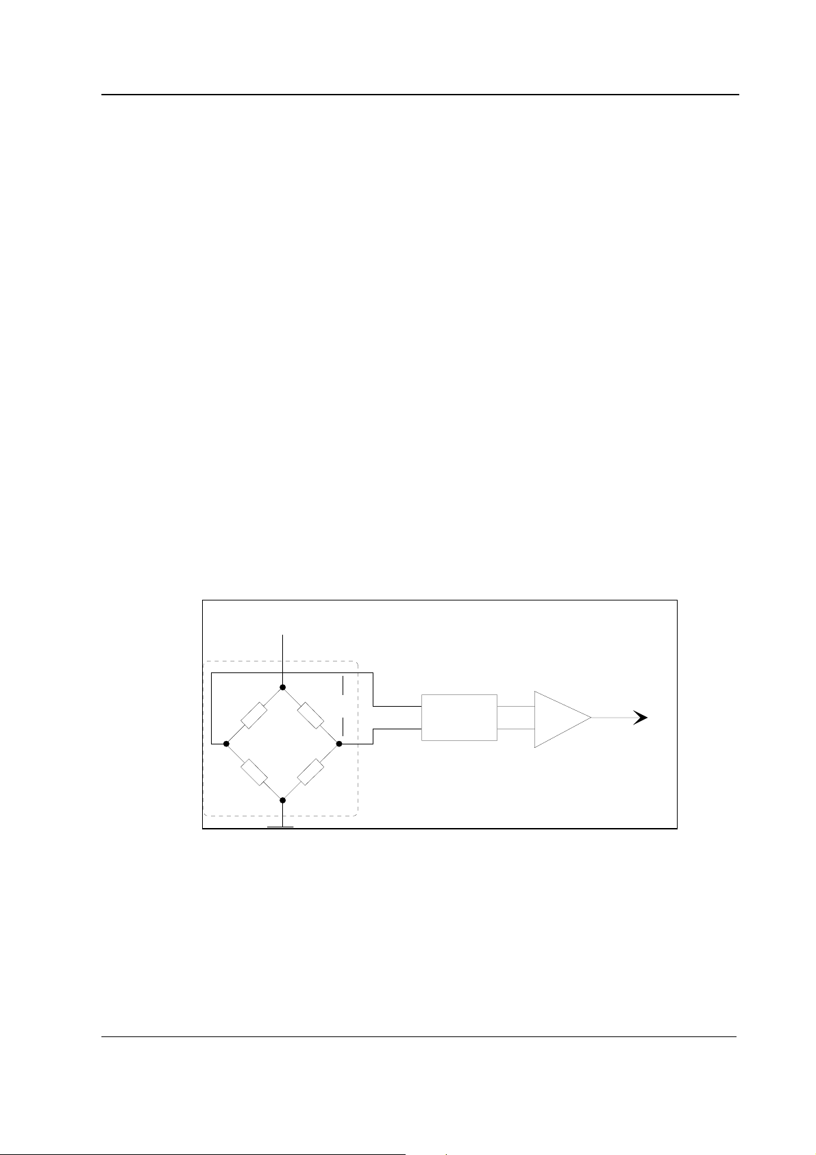
Invasive blood pressure measurement unit
An isolated +5 V supply is connected to the input of the pressure transducer bridge circuit. From
the bridge circuit output a differential voltage, which depends on blood pressure and input supply
voltage, is calculated using the following formula:
Uout = Uin × Pressure × 5 V
Pressure Module, M-P and Pressure Temp Module, M-PT
where Uin = 5 V
Uout = 25 V × Pressure [mmHg]
Pressure amplification is performed by the instrumentation amplifier. The gain of the amplifier is
set so that the level of the signal transferred to the A/D converter stays within the measurement
range even when there are circumstantial offsets or offsets caused by the pressure transducer. The
input filter before the amplifier attenuates high frequency disturbances.
Vin
Pressure
transducer
Vout
Input
Filter
Instrumentation
amplifier
G
to AD converter
Figure 4 Pressure transducer principle of operation
Temperature measurement unit
Value of NTC-resistor in the probe depends on patient’s temperature. It is measured with the
following principle.
The temperature signal(s) is produced by voltage dividers, part of which is the patient probe (YSI
400-series thermistor). The output is amplified by the calibrated amplifier(s) whose offset voltage
makes its output spread on both sides of zero. Wider output range (measurement range) means
better resolution.
7
Document No. 800 1013-1
Page 12
Datex-Ohmeda S/5 monitors
0 °C => 7K357
15 °C => 3K541
25 °C => 2K253
38 °C => 1K301
45 °C => 984R1
NTC
Figure 5 Temperature measurement principle
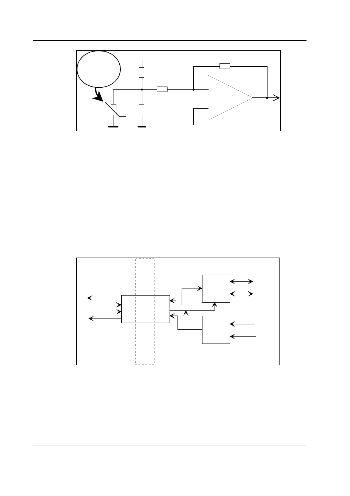
Serial communication
Serial communication between the module and the Central Unit is done by RS485 type bus whose
buffers get their supply voltage (+5 VDC) from the Central Unit and in the isolation section get the
supply voltage (+5 V) from the isolated power supply.
The communication drivers are controlled by a reset signal such that when the reset is active the
drivers do not transfer data.
Reset is also RS485 type and additionally, there is an auxiliary logic power reset, which keeps the
reset active for about 500 ms despite the state of reset in the module bus. A time constant
determines the power-up reset time. There are components to prevent the module from sending
data during reset. The data transmission rate is 500 kbps.
+5Vreference
A1
to AD
converter
offset
Isolated section
r
o
Receive data
sess
o
r
send
p
e
Send
/receive
dat
Reset
a
Opto isolation
Receive data
Send data
Reset
RS485
Driver
send/r
RS485
Driver
Data
NDa
eceive
Reset in
NReset in
)
nit
s
t
a
u
l
ra
bu
e
nt
ce
to
(modul
to modul
Patient
Isolation
Figure 6 Serial communication and opto isolation section
There are two opto isolators, one for data and one for the reset signal. Signals are processed on
logical high-low levels even though the output of the opto isolators in the isolation section are
analog signals.
8
Document No. 8001013-1
Page 13

The reset line is an open collector type with a pull-up resistor so that the microprocessor is able to
use its internal watchdog function.
Power supply section
Isolated supply voltage of the module is developed from +15 Vdirty voltage from the Central Unit.
Power supply is a switched-mode circuit, where FET transistor switch is controlled by an oscillator
using bipolar timer. The frequency of the oscillator is about 30 kHz and pulse ratio 50 %.
Controlling of the FET switch is slowed to suppress spurious interference.
A special pulse transformer is used in the circuit. The transformer secondary circuit uses normal
linear regulators except for +5 V which uses a low drop type linear regulator.
Pressure Module, M-P and Pressure Temp Module, M-PT
Document No. 800 1013-1
9
Page 14

Datex-Ohmeda S/5 monitors
2.3 Connectors and signals
2.3.1 Module bus connector
13
25
1
14
Figure 7 Module bus connector (X1)
Pin No I/O Signal
1 I RESET_RS485*
2 I -15 VDC*
3 I +15 VDIRTY*
4 I +15 Vin*
5 I/O NDATA_RS485*
6 I/O DATA_RS485*
7 Ground*
8 I NRESET_RS485*
9 I CTSB
10 O RTSB
11 I RXDB
12 O TXDB
13 Ground*
14 I +32 VDIRTY
15 I GroundDIRTY*
16 I CTSC
17 O RTSC
18 I RXDC
19 O TXDC
20 ON/STANDBY
21 O PWM_ECG*
22 RXDD_RS232
23 TXDD_RS232
24 I +5 VDCin*
25 I +5 VDC*
10
Document No. 8001013-1
* Used in the M-PT module
Page 15

2.3.2 Front panel connectors
Pressure connector (P3)
Pin No Signal
6
3
9
1
4
7
0
2
5
8
1 Pressure 3 +
2 Pressure 3 -
3 Polarization - (ground)
4 Polarization +
5 Not connected
6 Not connected
7 Not connected
8 Not connected
9 Ground
10 Cable detection
Signal out connector (Sync. out)
Pin No Signal
3
2
4
1
1 ECG out, 1 V/ 1 mV
2 Pressure out, 1 V/ 100 mmHg
3 ECG out, 1 V/ 1 mV
4 Ground
Pressure Module, M-P and Pressure Temp Module, M-PT
NOTE: The ECG out signal is not available with modules M-ESTP rev. 01, M-EST rev. 00 and M-ETP
rev. 00.
2.3.3 Other connectors
Keyboard connector (X3)
Pin No Signal Notes
1 N/C Not connected
2 COSWITCH Not used
3 PSWITCH for zeroing of P3
4 fGND Floating GND
5 fGND Floating GND
X3
1
5
11
Document No. 800 1013-1
Page 16

Datex-Ohmeda S/5 monitors
Pressure sensor connector (X4)
Pin No
board
1 0 PCABEL 5V if cable not connected
2 4 PCURRENT Pulsed supply to sensor
3 3,9 P3- Signal from the sensor
4 1 P3+ Signal from the sensor
5 2 fGND Floating GND
When the board is used in the M-PT module, there are the following connectors connected on the
board in addition to X1 and X4.
Signal out connector (X5)
Pin No
board
1 - ECG OUT ECG to (e.g.) IABP
2 - N/C Not connected
3 4 GND +5VDCin GND
4 1 ECG OUT ECG to (e.g.) defib.
5 - N/C Not connected
6 3 ECG OUT ECG to (e.g.) IABP
7 2 P OUT P3 to (e.g.) IABP
8 GND GND +5VDCin GND
Pin No
fr.panel
Pin No
fr.panel
Signal Notes
X4
1 5
Signal Notes
X5
1 8
Connector for temperature probes (X8)
Pin No Signal Notes
1T3-
2T4-
3 fGND Floating GND
4 CON Low if PT
5 fGND Floating GND
6 GND Floating GND
X8
1 6
12
Document No. 8001013-1
Page 17

Pressure Module, M-P and Pressure Temp Module, M-PT
3 SERVICE PROCEDURES
3.1 General service information
Field service of the M-P and M-PT modules is limited to replacing faulty circuit boards or
mechanical parts. The circuit boards should be returned to Datex-Ohmeda for repair.
Datex-Ohmeda is always available for service advice. Please provide the unit serial number, full
type designation, and a detailed description of the fault.
CAUTION Only trained personnel with appropriate equipment should perform the tests and
repairs outlined in this section. Unauthorized service may void warranty of the unit.
3.2 Service check
These instructions include complete procedures for a service check. The service check is
recommended to be performed after any service repair. However, the service check procedures can
also be used for determining possible failures.
The procedures should be performed in ascending order.
The instructions include a check form (Appendix A) which should be filled in when performing the
procedures.
The mark
procedure.
The procedures are designed for monitors with S/5 monitor software of revision 01. However, most
of the procedures also apply to monitors, which contain some other monitor software
type/revision.
? in the instructions means that the check list should be signed after performing the
3.2.1 Recommended tools
Tool Order No. Notes
M-NE(12)STPR/M-ESTPR/M-ESTP Not M-ESTP Rev. 01, M-EST Rev. 00 or M-ETP
Rev. 00
Patient simulator
Pressure manometer
Temperature test set 884515
InvBP transducer
Oscilloscope
Screwdriver
13
Document No. 800 1013-1
Page 18

Datex-Ohmeda S/5 monitors
All modules
• Detach the module box by removing the two screws from the back of the module. Be careful
with the loose latch and spring locking pin.
1. Check internal parts:
• screws are tightened properly
• cables are connected properly
• all socket mounted IC’s are inserted properly
• EMC covers are attached properly
• there are no loose objects inside the module
?
2. Check external parts:
• the front cover and the front panel sticker are intact
• all connectors are intact and are attached properly
• the module box, latch and spring locking pin are intact
?
• Reattach the module box and check that the latch is moving properly.
• Switch the monitor on and wait until the monitoring screen appears.
Configure the monitor screen so that all the needed parameters are shown, for example as
follows:
Monitor Setup - Screen 1 Setup - Waveform Fields - Field 1 - ECG1
Field 2 - P1
Field 3 - P3
Field 4 - P5
Digit Fields
Field 4 - T3+T4
3. Plug in the module. Check that it goes in smoothly and locks up properly.
?
• Preset InvBP measurement settings:
Invasive Pressures - P1 ‘Art’ Setup - Label - Art
P3 Setup - Label – PA
14
Document No. 8001013-1
Page 19

Pressure Module, M-P and Pressure Temp Module, M-PT
4. Enter the service menu:
Monitor Setup - Install/Service (password 16-4-34) - Service - (password 26-23-8)
Take down the information regarding module software by selecting SCROLL VERS and turning
the ComWheel.
?
5. Enter the P/PT service menu (according to the tested module):
Parameters - P/PT
Check that the “Timeouts”, “Bad checksums” and “Bad c-s by mod” values are not increasing
faster than by 50 per second. Check also that the module memories have passed the internal
memory test, i.e. the “RAM”, “ROM” and “EEPROM” show all OK.
?
Invasive blood pressure measurement
6. Check the front panel membrane key.
Press the key at least for one second. Check that the pressed key is identified, i.e. the text for
“Button” changes from OFF to ON in the service menu.
?
7. Check that the “Cable” and “Probe” show OFF.
Plug a cable with an invasive blood pressure transducer into the front panel connector P3.
Check that the “Cable” and “Probe” show ON and the pressure
8. waveform field appears onto the monitor screen..
NOTE: Test both invasive blood pressure channels with M-PP.
?
9. Calibrate the InvBP channel according to the instructions in the Technical Reference
Manual.
?
10. Check that the module configuration is correct with P and PT modules.
The configuration in use is shown beside the text “Configuration” in the service menu and it
can be either BP or PT.
Change the configuration in the CALIBRATIONS -menu, if necessary.
?
11. Check the InvBP channels with a patient simulator
Document No. 800 1013-1
15
Page 20

Datex-Ohmeda S/5 monitors
The settings and checks with a Dynatech Nevada medSim 300 Patient Simulator are:
SENSITIVITY switch position: 5 µV/V/mmHg
ECG - BASE - BPM - 60
ATM
connect a cable from the channel BP3 to the connector P3.
Ccheck that appropriate InvBP waveform is shown and the InvBP value is approximately
25/10 (±2 mmHg).
?
Modules with temperature measurement
BP - 2 - WAVE -
11. Check that the “Cable” and “Probe” show OFF for the channels T3 and T4 when no probes are
connected.
Connect a temperature test plug into the connector T3. Check that the “Cable” and “Probe”
for T3 show ON and the corresponding temperature value appears onto the screen.
Perform the same check also for the channel T4.
?
12. Check the temperature calibrations using temperature test plugs.
If the deviation on a temperature reading on the screen is more then 0.1 °C, calibrate the
temperature channels according to the instructions in the Technical Reference Manual.
?
13. Activate the temperature test by selecting TEMP TEST from the menu and pressing the
ComWheel twice. When the message “Performing temp test” disappears from the digit field
for T3+T4, check that no error messages appear and “Temp error” shows OFF for both
channels in the menu.
?
16
Document No. 8001013-1
Page 21

Modules with signal output connector
• Preset InvBP and ECG measurement settings:
Invasive Pressures - P3 Setup - Label - Art
ECG - ECG1 LEAD -I
Connect a patient simulator to the connector P3 and to the connector ECG on the used
M-NE(12)STPR/M-ESTPR/M-ESTP.
The settings and checks with a Dynatech Nevada medSim 300 Patient Simulator are:
SENSITIVITY switch position: 5 µV/V/mmHg
BP - 1 - WAVE - ART
ECG - BASE - BPM - 160
PACE - WAVE - NSR
Pressure Module, M-P and Pressure Temp Module, M-PT
Use the channel BP1 for the connector P3.
14. Connect an oscilloscope between the signal out connector pins 1 (ECG out) and 4 (Ground).
3
2
4
1
Check that an analog signal which corresponds with the ECG waveform on the screen comes
out. The output signal’s ratio to the actual ECG signal should be around 1V/1mV.
Check that a similar output signal is coming out also from the pin 3 (ECG out).
?
15. Connect the oscilloscope between the signal out connector pins 2 (Pressure out) and 4
(Ground).
Check that an analog signal which corresponds with the InvBP waveform on the screen
comes out. The output signal’s ratio to the actual InvBP signal should be around
1V/100mmHg.
?
17
Document No. 800 1013-1
Page 22

Datex-Ohmeda S/5 monitors
All modules
16. Perform electrical safety check and leakage current test.
?
17. Check that the module functions normally after the performed electrical safety check.
?
18. Clean the module with suitable detergent.
?
• Fill in all necessary documents.
3.3 Disassembly and reassembly
Disassemble the M-P and M-PT modules in the following way. See the exploded view of the
module.
1. Remove the two screws from the back of the module.
2. Pull the module box slowly backwards and detach it from main body. Be careful with loose
latch and spring pin for locking.
3. To detach the PT board. The board can be removed by detaching two screws on the folio
side of the board near the front panel and disconnecting the two ribbon cables coming from
the front panel.
To reassemble the module, reverse the order of the disassembly steps.
CAUTION When reassembling the module, make sure that all cables are connected properly.
18
Document No. 8001013-1
Page 23

3.4 Adjustments and calibrations
3.4.1 Invasive pressure calibration
Perform pressure calibration whenever the pressure transducer (probe) is replaced with different
type of transducer.
1. Enter P/PT service menu: Monitor Setup - Install/Service - Service - Parameters
2. Enter Calibrations menu.
Pressure Module, M-P and Pressure Temp Module, M-PT
3. Connect a pressure transducer with a pressure manometer to the P3 connector. Select
Calibrate P3. Leave the transducer to room air pressure.
4. Press the ComWheel to start zeroing.
5. Supply a pressure of 100 mmHg...300 mmHg to the transducer. The recommended pressure
is 200 mmHg.
6. Set the pressure on the display to match the pressure reading on manometer and press the
ComWheel. A tolerance of ±1 mmHg is allowed.
7. The text 'calibrated' will appear on the display.
3.4.2 Temperature calibration
NOTE: For the temperature calibration, separate test plugs (25 °C and 45 °C) are necessary. A test
set of two plugs is available from Datex-Ohmeda, order code 884515.
Performe temperature calibration whenever the measured values deviate more than ±0.1.
1. Enter P/PT service menu (Monitor Setup, Install/Service, Service, Parameters).
2. Enter Calibrations menu.
3. Press the protect button at the bottom of the module and select OFF protect mode. Release
the button.
4. Select Calibrate T3/Calibrate T4.
19
Document No. 800 1013-1
Page 24

Datex-Ohmeda S/5 monitors
5. Insert calibration plug (25 °C) into T3/T4 connector.
6. Press the ComWheel.
7. Insert calibration plug (45 °C) into T3/T4 connector.
8. Press the ComWheel.
9. Press in the protect button at the bottom of the module and select ON protect mode.
Release the button.
20
Document No. 8001013-1
Page 25

Pressure Module, M-P and Pressure Temp Module, M-PT
4 TROUBLESHOOTING
4.1 Troubleshooting chart
See also the User's Reference Manual for more troubleshooting procedures.
4.1.1 Invasive blood pressure
Trouble Cause Treatment
Abnormally low
pressure
No pressure Defective transducer. Check transducer.
Not zeroedmessage
Zeroing failedmessage
Calibration failedmessage
Transducer wrongly positioned. Check mid-heart level and reposition transducer.
No pressure module plugged in. Check the module.
No waveform selected on screen. Check selected pressure waveforms by pressing
Monitor Setup key and selecting modify
waveforms.
Check that pressure transducer open to patient.
Measurement on, channel not zeroed. Zero the channel.
Unsuccessful zeroing of P3 (number field). Possibly due to pulsating pressure waveform.
Open the transducer to air and zero the channel.
Offset is > 150 mmHg. Open the transducer to air
and zero the channel.
Defective transducer. Replace it and zero the
channel.
Unsuccessful calibrating of P3 (number
field), possibly due to pulsating waveform.
Turn the transducer to sphygmomanometer and
try again (zeroing takes place first).
Out of range ≤40
mmHg
Out of range >320
mmHg
Zero adj. >100
mmHg
Out of range Measured pressure is beyond the internal
Measurement pressure is beyond
measurement range.
Measurement pressure is beyond
measurement range.
Offset when zeroing is >100 mmHg (but
<150 mmHg) from the absolute zero of the
module (with default gain).
measurement range of the module.
Gain is beyond the limits (±20 % of the default
gain). Replace the transducer.
Check transducer level. Zero the channel.
Check transducer level. Zero the channel. The
patient may also have high pressure.
Check transducer. The waveform may hit the top
and the numeric display not shown.
The waveform hits the top and the numeric
display not shown. Check transducer and its
level. Zero the channel.
21
Document No. 800 1013-1
Page 26

Datex-Ohmeda S/5 monitors
4.1.2 Temperature
Trouble Cause Treatment
Message
'TEMPERATURE ERROR'
No temperature displayed Wrong type of probe.
Faulty calibration. Perform calibration. If it does not
Temperature out of measurable range.
Temperature calibration not protected.
help, check that front panel
connectors are properly connected to
STP board.
Use correct probe.
The range is between 10 and 45 °C.
Set the Protection ON in the Service
Menu.
22
Document No. 8001013-1
Page 27

4.2 Troubleshooting flowchart
Po ss ibl y fau lty
M-P/PT module
Take all modules out
of the Frame
Inse rt M-P /PT and turn
the power on
Pressure Module, M-P and Pressure Temp Module, M-PT
Does fault
still appear?
Yes
Enter the Service menu
Module-ID
on screen?
Yes
Check front panel key
functions in Service
menu
Do they work?
No
Check front panel unit
and PT board to
find culprit. Replace if
necessary
Yes
No
No
Has EEPROM
failed
No
Has Temp
measurement
failed?
No
Fault not in M-P/PT
module
No
Does another
module work
in the same slot?
Yes
Replace the PT board
Yes
Replace the PT board
Yes
Recalibrate the temp
channels
OK ?
No
Replace the PT board
No
Has InvBP
measurement
failed
Yes
Recalibrate the
InvBP channel
Figure 8 Troubleshooting flowchart
OK ?
23
Document No. 800 1013-1
Page 28

Datex-Ohmeda S/5 monitors
5 SERVICE MENU
1. Press the Monitor Setup key.
2. Select Install/Service (password 16-4-34).
3. Select Service (password 26-23-8).
4. Select Parameters.
5. Select P/PT module.
24
Document No. 8001013-1
Page 29

5.1 P/PT menu
Pressure Module, M-P and Pressure Temp Module, M-PT
Calibrations See section 5.2 “Calibrations menu.”
Record Data Record Data prints out the shown service data and board information (id., serial number, and
software id.) onto the recorder module, M-REC.
Service Data Gain is a coefficient to compensate gain error. Usually the value for P3 is between 17000 and
25000 and for T3 and T4 between 13000 and 14300. Zero indicates offset compensation value
of each parameter in A/D converter. Typically the values for P3 is within ±1000 and for T3 and T4
between -150 and +300. Calibrate if zero and/or gain value is outside the ranges.
Cable shows ON when the corresponding cable is connected to the front panel and Probe shows
ON when the corresponding probe is connected to the cable.
Under Value the measured numeric values are displayed simultaneously. Pressure value is a real
time value and shown in mmHg.
Button; the front panel key function can be confirmed by pressing the key and checking that OFF
turns to ON.
Temp error shows whether the calibration of the temperature was successful or not.
Protect key shows normally OFF but turns to ON when the button at the bottom of the module is
pressed.
Protect mode is normally ON. It turns to OFF when Protect is switched to OFF for the temperature
calibration in Calibration Menu.
Configuration shows the chosen module configuration: BP or PT.
Timeouts is a cumulative number that indicates how many times the module has not responded to
the monitor's inquiry.
Bad checksums is also a cumulative number that indicates how many times communication from
the module to monitor broke down.
Bad c-s by mod is a cumulative number that indicates how many communication errors the
module has detected.
The monitor starts counting these items at power up and resets to zero at power off. The nonzero
25
Document No. 800 1013-1
Page 30

Datex-Ohmeda S/5 monitors
values do not indicate a failure, but the continuous counting (more than 50 per second) during the
normal operation indicates either serial communication failure or module not in place.
RAM indicates the state of the RAM memory. ROM indicates whether the checksum in the EPROM
is in accordance with the one the software has calculated. EEPROM indicates if the values stored
in the permanent memory are valid. The state is either OK, Fail or ? (module not in place or a
communication error).
5.2 P/PT calibration menu
Protection Protection for the configuration and temperature calibrations can be set ON and OFF only when
protect button at the bottom of the module is pressed.
Set Config The module configuration should be set according to the module type. The setting is possible only
when the protection is set OFF. The available selections are BP or PT.
The configuration setting should be checked if the PT board is replaced.
Calibrate T3 and Calibrate T4
The functions are for calibrating the temperature channels T3 and T4. The calibrations are possible
only when the protection is set OFF. The temperature calibration requires accurate test plugs of
value 25 °C and 45 °C.
Calibration:
1. Select Calibrate T3 / Calibrate T4
2. Insert the test plug 25 °C into the T3 / T4 connector
3. Press the ComWheel
4. Insert the test plug 45 °C into the T3 / T4 connector
5. Press the ComWheel
Calibrate P3 The function is for calibrating the invasive blood pressure channel P3.
The calibration requires a pressure transducer (with an appropriate cable) and a pressure
manometer.
26
Document No. 8001013-1
Page 31

Pressure Module, M-P and Pressure Temp Module, M-PT
Calibration:
1. Connect the pressure transducer with the pressure manometer to the P3 connector. Select
Calibrate P3. Leave the transducer to room air pressure.
2. Press the ComWheel to start zeroing.
3. Supply a pressure of 100 mmHg to 300 mmHg to the transducer. The recommended
pressure is 200 mmHg.
4. Set the pressure on the display to match the pressure reading on the manometer and press
the ComWheel.
27
Document No. 800 1013-1
Page 32

Datex-Ohmeda S/5 monitors
6 SPARE PARTS
6.1 Spare parts list
NOTE: Only changed part numbers are listed under later revisions. To find the desired part: check
first the list of the revision that corresponds your device. If the part is not listed there, check the
previous revision, etc. until you find the right number.
NOTE: Accessories are listed in the Patient Monitor Supplies and Accessories.
6.1.1 Pressure Module, M-P, Rev. 00
4
1
3
2
5
Item Description Order No.
- Membrane keypad 880101
1 Module box (single width) 886167
2 Spring pin for module box 879182
3 Latch for module box 879181
4 Cross recess screw M3x8 black 616215
5 Front panel unit, M-P 880044
6 STP board, M-ESTP (Rev. 01), M-P (Rev. 00-01) *(880339) Use 885697
11 Metal frame 879184
13 Cross cylinder head screw M3x6 61721
14 Cross cylinder head screw M3x12 628700
15 Cross cylinder head screw M3x6 628710
16 Shakeproof washer 63611
28
Document No. 8001013-1
Page 33

6.1.2 Pressure Module, M-P, Rev. 01
No new spare parts.
6.1.3 Pressure Module, M-P, Rev. 02
Item Description Order No.
6 STP board, M-ESTP (Rev. 03-04), M-P (Rev. 02) *(882627) Use 885697
6.1.4 Pressure Module, M-P, Rev. 03
Item Description Order No.
6 PT board, M-PT (Rev. 01), M-P (Rev. 03) *895047
19 EMC cover 884099
20 Protection plate 883946
21 Insulation plate for 883946 884121
The front panel unit includes all the connectors and input boards.
* the part is recommended for stock
Pressure Module, M-P and Pressure Temp Module, M-PT
6.1.5 Pressure Module, M-P, Rev. 04
No new spare parts.
29
Document No. 800 1013-1
Page 34

Datex-Ohmeda S/5 monitors
6.1.6 Pressure Temp Module, M-PT, Rev. 00
Item Description Order No.
1 Module box (single width) 886167
2 Spring pin for module box 879182
3 Latch for module box 879181
5 Cross recess screw M3x8 black 616215
6 PT board, M-PT (Rev. 00) *885697
7 Signal out connector, M-PT 884316
8 T-Input connectors *884315
9 P-Input connector 884314
11 Metal frame 879184
13 Cross cylinder head screw M3x6 61721
14 Cross cylinder head screw M3x12 628700
15 Cross cylinder head screw M3x6 628710
16 Shakebroof washer 63611
17 Membrane keypad 880101
18 Front panel frame, M-PT 883801
19 EMC cover 884099
20 Protection plate 883946
21 Insulation plate for 883946 884121
30
Document No. 8001013-1
Page 35

Pressure Module, M-P and Pressure Temp Module, M-PT
6.1.7 Pressure Temp Module, M-PT, Rev. 01
Item Description Order no.
6 PT board, M-PT (Rev. 01), M-P (Rev.03) *895047
* the part is recommended for stock
6.1.8 Pressure Temp Module, M-PT, Rev. 02
No new spare parts.
6.1.9 Front panel stickers for AS/3 modules (square buttons)
Item No. 10
Front panel stickers that are related to the Compact Module type and adaptation:
Adaptation codes: DA=Danish, DE=German, EN=English, ES=Spanish, FI=Finnish,
FR=French, IT=Italian, JA=Japanese, NL=Dutch, NO=Norwegian, PT=Portuguese,
SV=Swedish
M-P
Adaptation
(Rev. 00-03)
Order No.
DA 892211 892210
DE 880488 885035
EN 880139 884004
ES 884201 886193
FI 888863 888864
FR 880130 885033
IT 886756 886758
JA 888308 888307
NL 886063 886330
NO 893569 893571
PT -- 895237
SV 885847 885845
M-PT
(Rev. 01)
Order No.
6.1.10 Front panel stickers for S/5 modules (round buttons)
Front panel stickers that are related to the Compact Module type and adaptation:
Adaptation codes: DA=Danish, DE=German, EN=English, ES=Spanish, FI=Finnish,
FR=French, IT=Italian, JA=Japanese, NL=Dutch, NO=Norwegian, PT=Portuguese,
SV=Swedish
31
Document No. 800 1013-1
Page 36

Datex-Ohmeda S/5 monitors
M-P
Adaptation
(Rev. 04)
Order No.
DA 898768 898768
DE 898735 898759
EN 898734 898758
ES 898738 898762
FI 898741 898765
FR 898736 898760
IT 898739 898763
JA 898745 898769
NL 898737 898761
NO 898743 898767
PT 898734 898764
SV 898742 898766
M-PT
(Rev. 02)
Order No.
32
Document No. 8001013-1
Page 37

7 EARLIER REVISIONS
This manual also supports M-P revisions 02 and 03.
For service information on the earlier revisions, please refer to:
P Module revision 00 Service Manual p/n 880850
P Module revision 01 Service Manual p/n 882580
Pressure Module, M-P and Pressure Temp Module, M-PT
33
Document No. 800 1013-1
Page 38

Datex-Ohmeda S/5 monitors
34
Document No. 8001013-1
Page 39

APPENDIX A, Service Check Form, M-P and M-PT
APPENDIX A
35
Document No. 800 1013-1
Page 40

Datex-Ohmeda S/5 monitors
36
Document No. 800 1013-1
Page 41

SERVICE CHECK FORM
Pressure Modules, M-P, M-PT
Customer
APPENDIX A, Service Check Form, M-P and M-PT
Service
Service engineer Date
OK = Test OK N.A. = Test not applicable Fail = Test Failed
All modules
OK N.A. Fail OK N.A. Fail
1. Internal parts 2. External parts
3. Installation
Notes
4. Module software
P
PT
Module type S/N
5. Communication and
memories
Notes
InvBP measurement
6. Membrane keys 7. Cable and transducer
detection
8. Calibration 9. Configuration BP/PT
10. Test with patient
simulator
Notes
A-1(2)
Document No. 8001013-1
Page 42

Datex-Ohmeda S/5 monitors
OK = Test OK N.A. = Test not applicable Fail = Test Failed
TEMP measurement
11. Temperature probe detection 12. Calibration check
13. Temp test -function
Notes
Signal output
14. ECG output 15. InvBP output
Notes
All modules
16. Electrical safety check 17. Functioning after
electrical safety
check
18. Final cleaning
Notes
Notes
Used Spare Parts
Signature
A-2(2)
Document No. 800 1013-1
 Loading...