

Page 1

Datex-Ohmeda
S/5™ Extension Frame, F-EXT4 (Rev. 03)
S/5™ Extension Module, M-EXT (Rev. 02)
Technical Reference Manual
Datex-Ohmeda Inc.
3030 Ohmeda Drive
53707-7550 MADISON, WIS
USA
Tel. +1-608-221 1551, Fax +1-608-222 9147
www.us.datex-ohmeda.com
All specifications are subject to change without notice.
Document No. 8001007-1
June 2001
Datex-Ohmeda Division,
Instrumentarium Corp.
P.O. Box 900, FIN-00031
DATEX-OHMEDA, FINLAND
Tel. +358 10 394 11 Fax +358 9 146 3310
www.datex-ohmeda.com
Instrumentarium Corp. All rights reserved.
Page 2

Page 3

Table of contents
TABLE OF CONTENTS
Extension Frame, F-EXT4 and Extension Module, M-EXT
TABLE OF CONTENTS i
Introduction 1
1 Specifications 2
1.1 General specifications..............................................................................................................................2
2 Functional Description 3
2.1 Connectors and signals.............................................................................................................................4
2.1.1 Module bus connector......................................................................................................................4
2.1.2 Other connectors..............................................................................................................................5
3 Service Procedures 6
3.1 Service check...........................................................................................................................................7
3.1.1 Recommended tools........................................................................................................................7
3.2 Disassembly and reassembly..................................................................................................................11
3.2.1 Changing the fuse...........................................................................................................................11
4 Troubleshooting 12
4.1 Troubleshooting chart.............................................................................................................................12
5Service menu 13
6 Spare Parts 14
6.1 Spare parts list.......................................................................................................................................14
6.1.1 Extension Frame, F-EXT4 Rev. 01 ....................................................................................................14
6.1.2 Extension Frame, F-EXT4 Rev. 02 ....................................................................................................15
6.1.3 Extension Frame, F-EXT4 Rev. 03 ....................................................................................................15
6.1.4 Extension Module, M-EXT Rev. 01, M-EXT Rev. 02............................................................................16
6.1.5 Stickers.........................................................................................................................................16
7 EARLIER REVISIONS 17
APPENDIX A
19
Service check FORM A-1
Document No. 8001007-1
i
Page 4

Datex-Ohmeda S/5 monitors
ii
Document No. 8001007-1
Page 5

INTRODUCTION
The Extension Frame, F-EXT4 is designed for use with S/5 monitors and provides four additional
module slots, and enables taking the measuring modules near to the patient. The extension frame,
F-EXT4 is connected to the monitor with the extension module, M-EXT, which reserves one module
slot.
NOTES:
• Only one F-EXT4 can be connected to the monitor at a time.
• The following modules cannot be used in the F-EXT4
• Do not use identical modules simultaneously in the extension frame and in the host
Extension Frame, F-EXT4 and Extension Module, M-EXT
− Recorder Module, M-REC
− Memory Module, M-MEM
− Interface Module, M-INT
− Compact Airway Modules, M-Cxxxxx
monitor.
• When the extension frame is used with the S/5 Anaesthesia Monitor the F-CU8 must be of
rev. 03 or later.
Document No. 8001007-1
1
Page 6

Datex-Ohmeda S/5 monitors
1 SPECIFICATIONS
1.1 General specifications
Frame size, (W × D × H) 160 × 205 × 137 mm
(w/ module) 160 × 228 × 137 mm
Frame weight 1.3 kg
Power consumption 35 W (max at input voltage of +32 V) with
Module size, (W × D × H) 37 × 180 × 112 mm/1.5 × 7.1 × 4.4 in
ESTP and NIBP modules inserted and NIBP pump working.
2
Document No. 8001007-1
Page 7
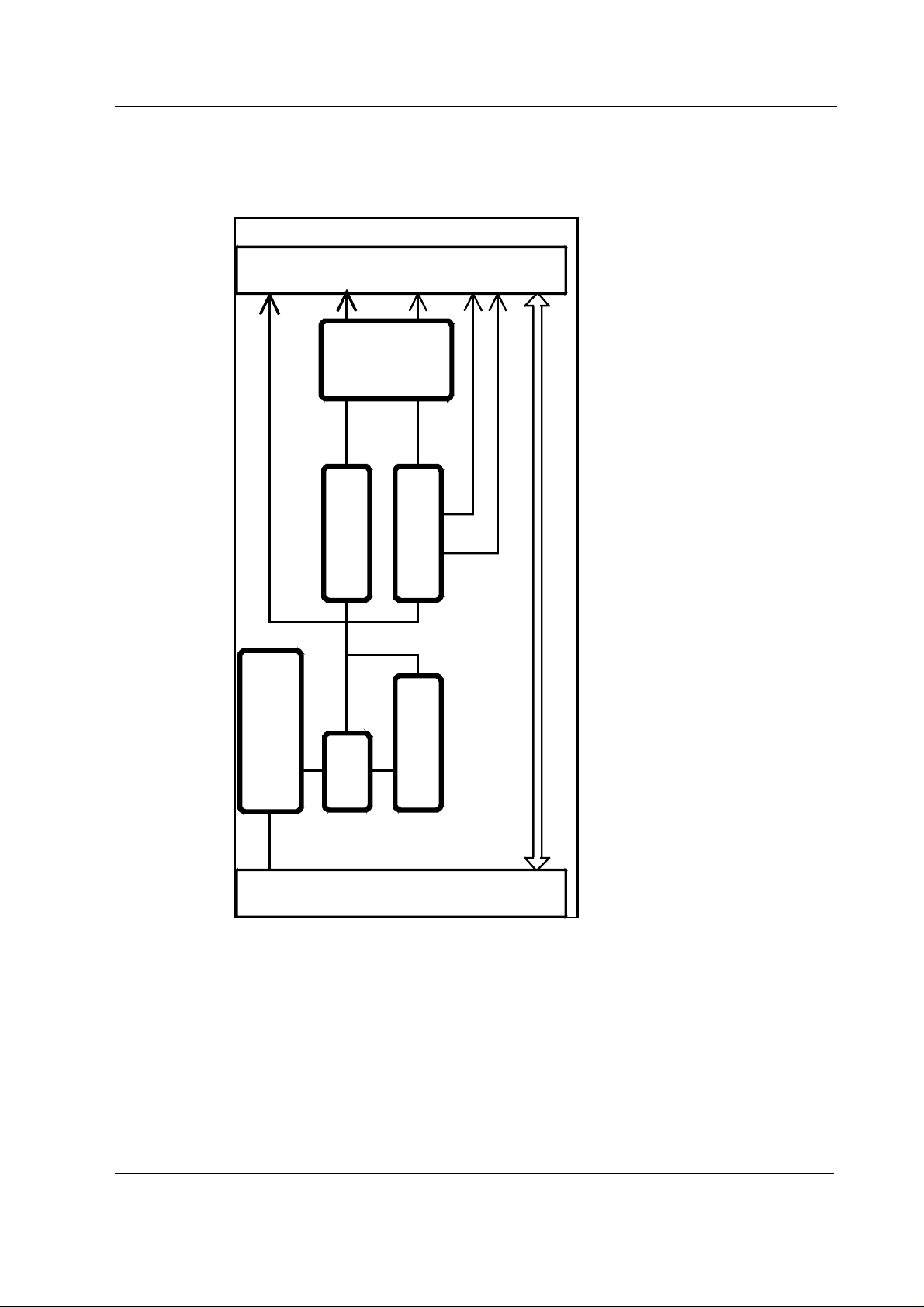
2 FUNCTIONAL DESCRIPTION
Four D-Connectors for Modules
Module Mother Board
OVERVOLTAGE
PROTECTION
FOR OUTGOING
VOLTAGES
Extension Frame, F-EXT4 and Extension Module, M-EXT
+32 V
OVERVOLTAGE
AND UNDERVOLTAGE
+32 V
+15 Vd
POWER
+15 V SWITCHING
PROTECTION
SOFT
START
SUPPLY
+5 V
DC/DC
CONVERTER
REMOTE ON/OFF
CONTROL
-15 V
+15 Va
DATA
Monitor Frame
Figure 1 F-EXT electronics unit block diagram
The Extension Frame, F-EXT4, contains the module mother board, power supply board, and space
for four single-width or two double-width modules.
The electronic unit receives +32 V from the monitor frame and generates from it necessary
operational voltages for the inserted modules. The received +32 V is passed through fuse (F1) and
filtered and led to power supply components.
There is overvoltage and undervoltage protection for input voltage, the input voltage is set so that it
can vary between +18.5 V and +36.0 V.
Document No. 8001007-1
3
Page 8
Datex-Ohmeda S/5 monitors
The purpose of the soft start is to raise input voltage +32 V slowly (a bout 1 second) to the
maximum value so that capacitors in power supply components' circuits have time to get charged.
This enables extension frame to be connected to monitor frame during operation.
There is also overvoltage protection for outgoing supply voltages. The overvoltage limits
are +5.95 V (+5 V) and +17.50 V (+15 Vd).
Signal Routes
There are two connectors which are used for data communications ( RS485), for supply voltages
(+32 V, +15 Vd, +15 Va, and +5 V), for grounds connections (GNDD, GND&SHIELD) between the
power supply board and module mother board.
2.1 Connectors and signals
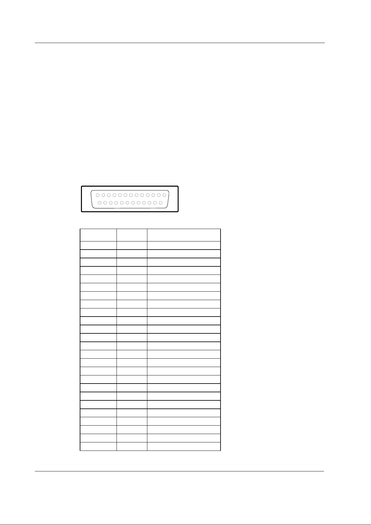
2.1.1 Module bus connector
13
25
1
14
Module bus connector (X1)
Pin No I/O Signal
1 I RESET_RS485*
2 I -15 VDC*
3 I +15 VDIRTY*
4 I +15 VDC*
5 I/O -DATA_RS485*
6 I/O DATA_RS485*
7 Ground & Shield*
8 I -RESET_RS485*
9 I CTSB
10 O RTSB
11 I RXDB
12 O TXDB
13 Ground & Shield*
14 I +32 VDIRTY*
15 I GroundDIRTY*
16 I CTSC
17 O RTSC
18 I RXDC
19 O TXDC
20 ON/STANDBY*
21 BIT0IN*
22 RXDD_RS232
23 TXDD_RS232
24 I +5 VDC*
25 I +5 VDC*
4
Document No. 8001007-1
* Used in the Extension Frame and in the Extension Module
Page 9

2.1.2 Other connectors
Extension Frame Rear panel connector (X1)
Extension Frame, F-EXT4 and Extension Module, M-EXT
D
C
EFG
M
L
A
B
Pin No I/O Signal
H
J
K
A I RESET_RS485
B I/O -DATA_RS485
C I/O DATA_RS485
D I -RESET_RS485
EODirect ECG
F-N/C
G I +32 VDC
H I Gnd and Shield (for data transmission)
J-N/C
K-N/C
L I +32 VDC
M I GndD (dirty) for power supply
Document No. 8001007-1
5
Page 10

Datex-Ohmeda S/5 monitors
3 SERVICE PROCEDURES
Field service of the Extension Frame, F-EXT4, is limited to replacing faulty circuit boards or
mechanical parts. The circuit boards should be returned to Datex-Ohmeda for repair.
Datex-Ohmeda is always available for service advice. Please provide the unit serial number, full
type designation, and a detailed description of the fault.
CAUTION Only trained personnel with the appropriate tools and equipment should perform
the tests and repairs outlined in this section. Unauthorized service may void
warranty of the unit.
6
Document No. 8001007-1
Page 11

3.1 Service check
These instructions include complete procedures for a service check. The service check is
recommended to be performed after any service repair. However, the service check procedures can
also be used for determining possible failures.
The procedures should be performed in ascending order.
Extension Frame, F-EXT4 and Extension Module, M-EXT
The instructions in clude a check form (
procedures.
The mark
the procedure.
The procedures are designed for monitors with S/5 monitor software of revision 01. However, most
of the procedures also apply to monitors, which contain some other monitor software
type/revision.
? in the instructions means that the check form should be signed after performing
Appendix A
) which should be filled in when performing the
3.1.1 Recommended tools
Tool Order No. Notes
M-ESTPR/M-ESTP
M-NIBP
Adult NIBP cuff & hose
Gas interface cable 884299
Multimeter
Screwdriver
General
• Disconnect the Extension Module, M-EXT from the host monitor, if connected.
• Disconnect the extension module cable from the Extension Frame, F-EXT4 rear panel.
Extension Module, M-EXT
• Detach the module box by removing the two screws from the back of the module. Be careful
with loose latch and spring pin for locking.
1. Check internal parts:
− all screws are tightened properly
− there are no loose objects inside the module
?
7
Document No. 8001007-1
Page 12

Datex-Ohmeda S/5 monitors
2. Check external parts:
− the front cover and the front panel sticker are intact
− the module bus connector is intact
− the module box, the latch and the spring pin are intact
− the extension module cable and its connector are intact
− the screw on the cable connector is tightened properly
?
• Reattach the module box and check that the latch is moving properly.
Extension Frame
3. Check that the plastic frame is intact.
?
4. Check that the extension frame mount is tightened properly to the plastic frame.
?
5. Check that the big fastening screw at the back of the mount is intact.
?
6. Check that all four rubber pads are in place at the bottom.
?
7. If the extension frame contains a fan (Rev. 02->), clean or replace the fan filter.
?
8. Check that the cable connector on the rear panel is clean and intact.
?
9. Check that the module motherboard connectors are clean and intact. Check also that the
screws that connect the module motherboard to the frame are tightened properly.
?
10. Check that the M-NIBP fits in smoothly and locks up properly in the slots in the extension
frame.
8
Document No. 8001007-1
Leave the module disconnected.
?
Page 13

General
Extension Frame, F-EXT4 and Extension Module, M-EXT
11. Measure resistance from the following module motherboard (F-EXT4) connector pins
against the ground:
Pin 1 +Reset RS485
Pin 5 -Data RS485
Pin 6 +Data RS485
Pin 8 -Reset RS485
Pin 13 Ground
13
25
14
1
Module motherboard connector
Check that the resistance on each of the pins is higher than 10 kΩ. If not, exchange the
module motherboard.
?
12. Connect and lock the extension module cable to the extension frame rear panel connector.
Make sure that the monitor used in checking is switched to STBY, then install the extension
module into the monitor. Check that the module goes in smoothly and locks up properly.
?
13. Connect the gas interface cable (the grounding plates of the cable should be removed) to
one of the extension frame module bus connectors.
Switch the monitor on and measure the module bus voltages from the loose gas interface
cable connector (see the pin order from the previous figure). The output voltages should
meet the following ranges:
Pin 2 -15V -14.50...-15.50V
Pin 3 +15VD 14.50...15.50V
Pin 4 +15V 14.50...15.50V
Pin 14 +32V 31.0...33.0V
Pin 24 +5V 4.80...5.30V
Pin 25 +5V 4.80...5.30V
If any of the voltages is not within the given tolerance, exchange the extension frame Power
supply board.
Disconnect the gas interface cable carefully.
?
14. If the extension frame contains a fan, check that the fan is running.
9
Document No. 8001007-1
Page 14

Datex-Ohmeda S/5 monitors
?
15. Install the ESTPR/ESTP and NIBP modules into the extension frame. Make sure that similar
modules are not installed into the monitor already. Check that the modules are recognized,
i.e. the needed parameter information is shown on the monitor screen.
NOTE: If nothing happens, make sure the screen configuration is appropriate.
Swap the modules in the extension frame and check that the modules are still recognized.
?
16. Detach the extension module, M-EXT from the monitor, then install it again. Check that the
modules in the extension frame are still recognized.
?
17. Disconnect the monitor’s power cord shortly during the monitor is on. Check that the
monitor recovers and the modules in the extension frame are still recognized.
NOTE: The monitor may give an audible alarm during the power loss.
?
18. Connect an adult NIBP cuff to the NIBP module and place the cuff onto your arm. Perform
one NIBP measurement and check that the monitor gives a reasonable NIBP reading.
?
19. Perform electrical safety check and leakage current test.
?
20. Check that the extension frame functions normally after the performed electrical safety
check.
?
21. Clean the extension frame and module with suitable detergent.
?
Fill in all necessary documents.
10
Document No. 8001007-1
Page 15

3.2 Disassembly and reassembly
Disassemble the Extension Fr ame, F-EXT4 in the following way. See the exploded view of the frame.
1. Remove the four screws from the front of the frame. PC board’s block is detached.
2. Remove the four screws from module mother board with which it is attached to the rear
frame.
3. Lift carefully module mother board and power supply board attached to it and detach the
two connectors under the power supply board.
3.2.1 Changing the fuse
Disassemble the F-EXT4 as described above. The fuse is located on the power supply board.
Replace the fuse by the one with the same type and rating.
Extension Frame, F-EXT4 and Extension Module, M-EXT
11
Document No. 8001007-1
Page 16

Datex-Ohmeda S/5 monitors
4 TROUBLESHOOTING
4.1 Troubleshooting chart
Trouble Cause Treatment
F-EXT4 does not work. Connector not connected properly.
Cable /Extension module is faulty.
F-EXT4 does not work. Incoming voltage too high or too low. Check the Central Unit output voltages. Replace the
F-EXT4 does not work. PC board(s) faulty. Check the fuse on the Power supply board
Fuse on power supply board is blown
repeatedly.
Short-circuit in output voltages. Change the fuse. Remove modules and turn power
Check connectors.
Check cable/module.
F-EXT4 power supply board, if necessary.
Check the PC boards and their connections.
Change Power supply board.
on.
If works, some module is faulty.
If not, check the PCBs. Change power supply board.
12
Document No. 8001007-1
Page 17

5 SERVICE MENU
There is no service menu for the extension frame.
Extension Frame, F-EXT4 and Extension Module, M-EXT
13
Document No. 8001007-1
Page 18

Datex-Ohmeda S/5 monitors
6 SPARE PARTS
6.1 Spare parts list
NOTE: Only changed part numbers are listed under later revisions. To find the desired part: check
first the list of the revision that corresponds your device. If the part is not listed there, check the
previous revision, etc. until you find the right number.
6.1.1 Extension Frame, F-EXT4 Rev. 01
Item Item description Order No.
1 Rear frame 881234
2 Fuse T2.5A fast *51118
3 Power supply board, F-EXT4 (Rev. 01) *884840
4 Module mother board, F-EXT4 (Rev. 01-02) 884839
5 Frame with rubber pads (881233) Use 893113
6 Internal connector cable 884838
7 Cross cylinder-head screw M3x6 61721
8 Nut bushing M3x9 640455
9 Cross cylinder-head screw M3x12 61736
10 Pad 65144
14
Document No. 8001007-1
Page 19

Extension Frame, F-EXT4 and Extension Module, M-EXT
6.1.2 Extension Frame, F-EXT4 Rev. 02
Item Item description Order No.
1 Rear frame 892379
3 Power supply board, F-EXT4 (Rev. 02) *892378
5 Frame with rubber pads 893113
11 Fan, F-EXT4 893141
12 Fan cover 892680
13 Fan filter *874594
14 Protection mesh 58201
15 Cross cylinder-head screw M3x18 61739
16 Slotted recess screw M3x6 61223
6.1.3 Extension Frame, F-EXT4 Rev. 03
Item Item description Order No.
1 Power covering 898316
5 Frame Housing 898317
16 Slotted recess screw M3x6 61620
15
Document No. 8001007-1
Page 20

Datex-Ohmeda S/5 monitors
6.1.4 Extension Module, M-EXT Rev. 01, M-EXT Rev. 02
4
1
3
2
5
Item Item description Order No.
1 Module box (single width) 886167
2 Latch 879181
3 Spring Pin 879182
4 Cross recess screw M3x8 black 616215
5 Front panel frame 882080
* this part is recommended for stock
6.1.5 Stickers
Front panel sticker for M-EXT
Adaptation M-EXT (Rev. 01) Order No. M-EXT (Rev. 02) Order No.
-00- 882085 8000212
16
Document No. 8001007-1
Page 21

7 EARLIER REVISIONS
F-EXT4 Rev. 01 see also service manual p/n 889535.
M-EXT Rev. 00 see also service manual p/n 889535.
Extension Frame, F-EXT4 and Extension Module, M-EXT
17
Document No. 8001007-1
Page 22

Datex-Ohmeda S/5 monitors
18
Document No. 8001007-1
Page 23

APPENDIX A, Service check form, F-EXT4 and M-EXT
APPENDIX A
19
Document No. 8001007-1
Page 24

Datex-Ohmeda S/5 monitors
20
Document No. 8001007-1
Page 25

SERVICE CHECK FORM
Extension Frame, F-EXT4
Customer
APPENDIX A, Service check form, F-EXT4 and M-EXT
Service
Service engineer Date
OK = Test OK N.A. = Test not applicable Fail = Test Failed
Extension Module
OK N.A. Fail OK N.A. Fail
1. Internal parts 2. External parts
Notes
Extension Frame
3. Plastic frame 4. Mounting plate
5. Fastening screw 6. Pads
Type S/N
7. Fan filter 8. Cable connector
9. Module motherboard
connectors
Notes
General
11. Communication lines
+Reset RS485 (pin 1) > 10 kΩ
-Data RS485 (pin 5) > 10 kΩ
+Data RS485 (pin 6) > 10 kΩ
-Reset RS485 (pin 8) > 10 kΩ
12. M-EXT installation
10. Module motherboard
position
A-1(2)
Document No. 8001007-1
Page 26

Datex-Ohmeda S/5 monitors
13. Voltages
- 15 V (pin 2) -14.50...-15.50V
+ 15 VD (pin 3) 14.50...15.50 V
+ 15 V (pin 4) 14.50...15.50 V
+ 32 V (pin 14) 31.0...33.0 V
+ 5 V (pin 24) 4.80...5.30 V
+ 5 V (pin 25) 4.80...5.30 V
14. Fan 15. Module
communication
16. Restarting 1. 17. Restarting 2.
18. Test measurement with
module
Notes
19. Electrical safety check 20. Functioning after
electrical safety
check
21. Final cleaning
Notes
Used Spare Parts
Signature
A-2(2)
Document No. 8001007-1
 Loading...