

Page 1
Datex-Ohmeda
S/5™ Nellcor Compatible Saturation Module, M-NSAT (Rev. 03)
S/5™ Datex-Ohmeda Oxygen Saturation Module, M-OSAT (Rev.00)
Technical Reference Manual Slot
Datex-Ohmeda Inc.
3030 Ohmeda Drive
53707-7550 MADISON, WIS
USA
Tel. +1-608-221 1551 Fax +1-608-2229147
www.us.datex-ohmeda.com
All specifications are subject to change without notice.
Document No. 8002219
June 2001
Datex-Ohmeda Division,
Instrumentarium Corp.
P.O. Box 900, FIN-00031
DATEX-OHMEDA, FINLAND
Tel. +358 10 394 11 Fax +358 9 146 3310
www.datex-ohmeda.com
Instrumentarium Corp. All rights reserved.
Page 2

Page 3

Table of contents
TABLE OF CONTENTS
Nellcor Compatible Saturation Module, M-NSAT
Datex-Ohmeda Oxygen Saturation Module, M-OSAT
TABLE OF CONTENTS i
TABLE OF FIGURES ii
Introduction 1
1 Specifications 3
1.1 General specifications ..............................................................................................................................3
1.2 Typical performance of M-NSAT.................................................................................................................3
1.3 Typical performance of M-OSAT.................................................................................................................4
2 Functional description 5
2.1 Main components of M-NSAT ....................................................................................................................5
2.2 Main components of M-OSAT ....................................................................................................................5
2.2.1 NIO and OIO Interface board .............................................................................................................6
2.3 Connectors and signals.............................................................................................................................8
2.3.1 Module bus connector......................................................................................................................8
2.3.2 Other connectors..............................................................................................................................8
3 Service Procedures 9
3.1 General service information.......................................................................................................................9
3.2 Service check .........................................................................................................................................10
3.2.1 Recommended tools ......................................................................................................................10
3.3 Disassembly and reassembly..................................................................................................................12
4 Troubleshooting 13
4.1 Troubleshooting chart .............................................................................................................................13
4.2 Troubleshooting flowchart .......................................................................................................................14
5Service MENU 15
5.1 M-NSAT menu ........................................................................................................................................16
6 Spare Parts 17
6.1 Spare part lists of the M-NSAT.................................................................................................................17
6.1.1 Nellcor Compatible Saturation Module, M-NSAT rev. 00...................................................................17
6.1.2 Nellcor Compatible Saturation Module, M-NSAT rev. 01...................................................................17
6.1.3 Nellcor Compatible Saturation Module, M-NSAT rev. 02...................................................................18
6.1.4 Nellcor Compatible Saturation Module, M-NSAT rev. 03...................................................................18
6.1.5 Front panel stickers for AS/3 modules.............................................................................................18
6.1.6 Front panel stickers for S/5 modules...............................................................................................18
6.2 Spare part lists of M-OSAT.......................................................................................................................19
6.2.1 Datex-Ohmeda Oxygen Saturation Module, M-OSAT rev. 00 .............................................................19
6.2.2 Front panel stickers ........................................................................................................................20
7 Earlier Revisions 21
APPENDIX A 23
Document No. 8002219
i
Page 4

Datex-Ohmeda S/5 monitors
Service check FORM A-1
TABLE OF FIGURES
Figure 1 Nellcor Compatible Saturation Module, M-NSAT ...................................................................................... 1
Figure 2 Datex-Ohmeda Oxygen Saturation Module, M-OSAT .................................................................................1
Figure 3 NIO and OIO Interface board block diagram....................................................................................... 6
Figure 4 Module troubleshooting flowchart ...................................................................................................14
ii
Document No. 8002219
Page 5
INTRODUCTION
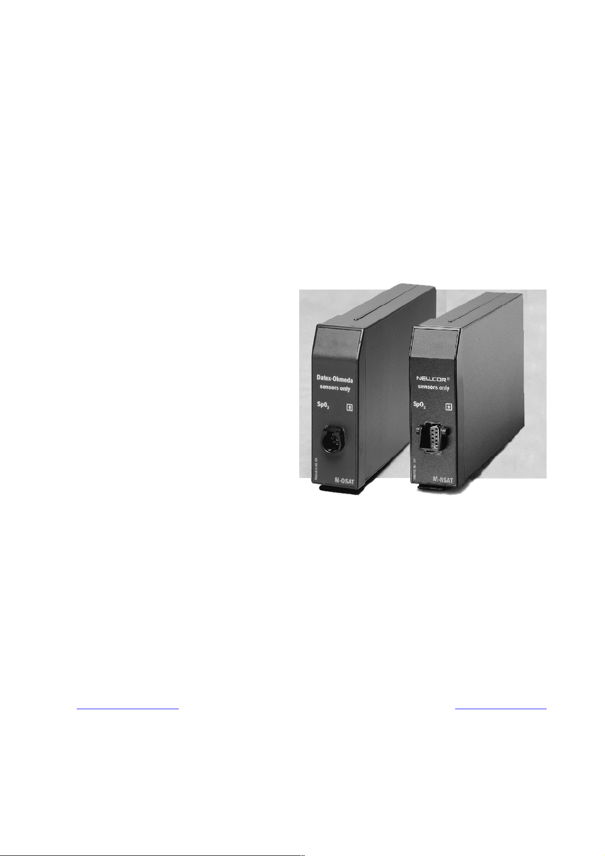
This section provides information for the maintenance and service of the Datex-Ohmeda Nellcor
Compatible Saturation Module, M-NSAT and the Datex-Ohmeda Oxygen Saturation Module, MOSAT. The M-NSAT and M-OSAT are single width plug-in modules designed for use with the S/5
monitors. The M-NSAT module utilizes Nellcor’s pulse oximetry algorithm and it should be used
with Nellcor’s pulse oximetry transducers only. The M-OSAT module utilizes Datex-Ohmeda pulse
oximetry algorithm and it should be used with Datex-Ohmeda OxyLead Compatible and Integrated
sensors. Only one pulse oximetry source at a time is allowed by the monitors. If M-NE(12)STPR/MNE(12)STR/M-ESTPR/M-ESTR and M-NSAT or M-OSAT modules are plugged in the monitor
simultaneously, then M-NSAT or M-OSAT overrides modules mentioned above as a pulse oximetry
source.
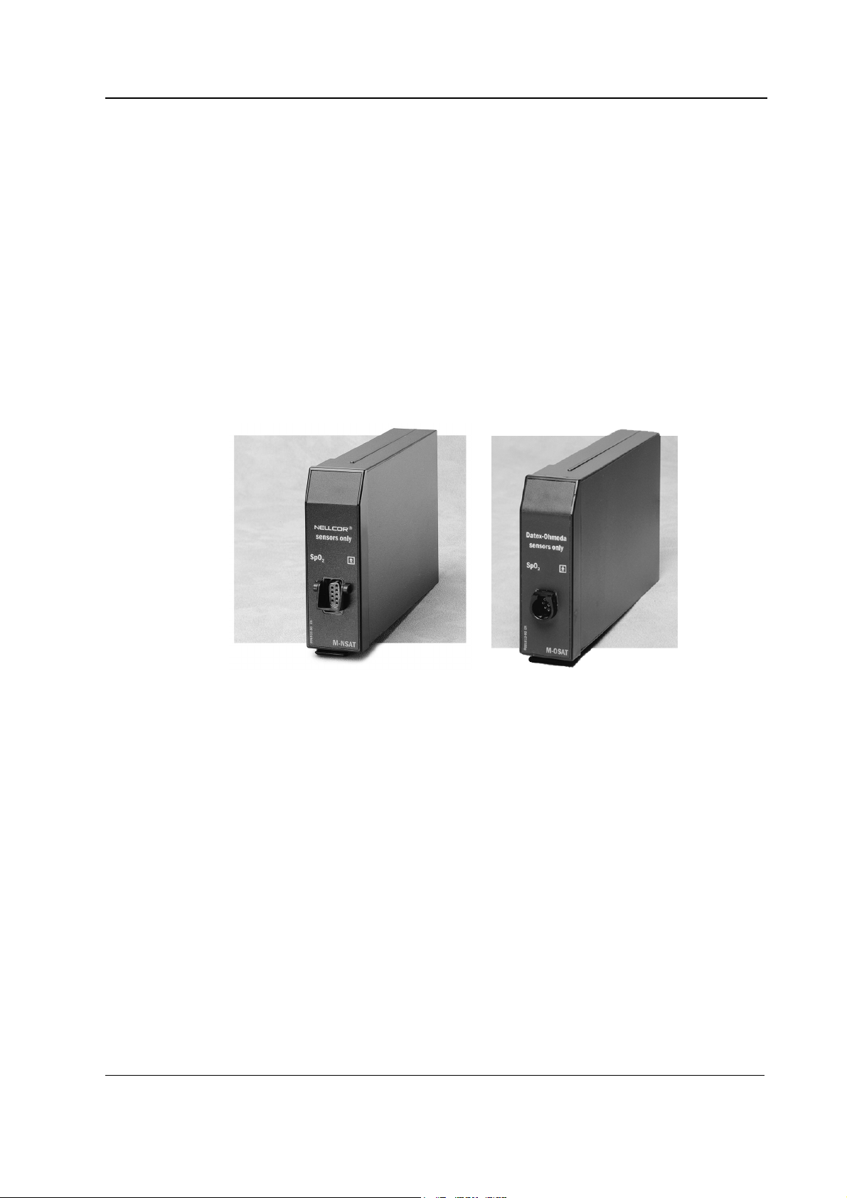
Oxygen Saturation Modules, M-NSAT, M-OSAT
Figure 1 Nellcor Compatible Saturation
Module, M-NSAT
Figure 2 Datex-Ohmeda Oxygen Saturation
Module, M-OSAT
1
Document No. 8002219
Page 6

Datex-Ohmeda S/5 monitors
2
Document No. 8002219
Page 7

1 SPECIFICATIONS
1.1 General specifications
Module size, (W × D ×H) 37 × 180 × 112 mm/1.5 × 7.1 × 4.4 in
Module weight 0.4 kg/1 lbs
Power consumption 3 W
1.2 Typical performance of M-NSAT
Measurement range and
display range 40 to 100 %
Calibration range 70 to 100%
Accuracy 100 to 70 %: ±2 digits
(% ±1 SD)
Resolution 1 digit = 1 %
Display averaging 5...7 s
Display update 5 s
Pulse beep pitch Varies with SpO
1
Oxygen Saturation Modules, M-NSAT, M-OSAT
69 to 50 %: ±3 digits
50 to 40 %: unspecified
level
2
The monitor is calibrated over the measurement range against functional saturation SpO
ALARM
Alarm default limits
high alarm OFF
low alarm 90%
HEART RATE FROM PLETH
Measurement range 20 to 250 bpm
Accuracy ±3 bpm
Resolution 1 bpm
Display averaging 5...7 s
Adjustable pulse beep volume
PLETH WAVEFORM
Scales Automatic scaling
Protection against electrical shock Type BF
(func).
2
1
1 SD (standard deviation) = 68 % of all readings in the specified range in stable conditions.
3
Document No. 8002219
Page 8

Datex-Ohmeda S/5 monitors
1.3 Typical performance of M-OSAT
Measurement range and
display range 40 to 100 %
Calibration range 70 to 100%
Accuracy 100 to 70 %: ±2 digits
(% ±1 SD)1 69 to 50 %: unspecified
Resolution 1 digit = 1 %
Display averaging 12 s typical
Display update 5 s
Pulse beep pitch Varies with SpO2 level
The monitor is calibrated over the measurement range against functional saturation SpO 2 (func).
ALARM
Alarm default limits
high alarm OFF
low alarm 90%
HEART RATE FROM PLETH
50 to 40 %: unspecified
Measurement range 30 to 250 bpm
Accuracy ±2 digits or ±2 bpm, whichever is greater
Resolution 1 bpm
Display averaging 12 s typical
Adjustable pulse beep volume
PLETH WAVEFORM
Scales Automatic scaling
Protection against electrical shock
Type BF
4
Document No. 8002219
Page 9

2 FUNCTIONAL DESCRIPTION
2.1 Main components of M-NSAT
The M-NSAT module consists of the following parts
Oxygen Saturation Modules, M-NSAT, M-OSAT
• SpO
sensor board
2
• Sensor connector cable
• Nellcor Pulse Oximeter Module MP-204
• NSAT interface board (NIO)
Sensors can be plugged into the M-NSAT module either directly or using sensor extension cables
available from Nellcor. Sensors are plugged into a 9-pin female connector (D-type) on the front
panel of the module. This connector is mounted on a small PC board, which is connected by a flat
cable to the MP-204.
The MP-204 is a surface mounted PC board manufactured by Nellcor Incorporated. It contains the
signal processing electronics and software that are based on Nellcor’s stand-alone pulse
oximeters. The MP-204 is used with an internal preamplifier.
The measured SpO
and pulse rate values, as well as status information, are transferred from the
2
MP-204 to the NSAT interface board. Communication between the MP-204 and NSAT interface
board is established through RS232C serial interface. The NSAT interface board, in turn, transmits
the measurement information to the module bus of the monitor through RS485 serial interface.
2.2 Main components of M-OSAT
The M-OSAT module consists of the following parts
• SpO
• Datex-Ohmeda Proloque module board
• OIO interface board
Sensor can be plugged into the M-OSAT module either directly or using sensor extension cables
available from Datex-Ohmeda. Sensors are plugged into a 9-pin female connector (DatexOhmeda) on the front panel of the module. This connector is mounted on a small PC board, which
is connected to the Proloque module by a cable. The EMC ferrite of this cable is mounted at the
back of the front panel.
sensor board and cable set
2
The Proloque module board is a surface mounted PC board manufactured by Datex-Ohmeda. It
contains the signal processing electronics and software. The Proloque module is used with an
internal preamplifier.
The measured SpO
and pulse rate values, as well as status information, are transferred from the
2
Proloque module to the OIO interface board. Communication between the Proloque module and
OIO interface board is established through RS232C serial interface. The OIO interface board, in
turn, transmits the measurement information to the module bus of the monitor through RS485
serial interface.
Document No. 8002219
5
Page 10

Datex-Ohmeda S/5 monitors
2.2.1 NIO and OIO Interface board
Module bus connector
RS485
Driver for
data
Opto isolation
Micropr ocessor, 488 byte internal RAM, 16kbyte
internal ROM; 16MHz
UART
Bidirectional asynchronous
serial com munication to
Nellcor oximeter module
or Proloque module
RS485
Driver for
module reset
Patient isolati on
Power-up
reset
Non-volatile
memory
Power;
non-isolated
section
Isolation transf ormer
Power;
isolated
section
+5V,+15V,-15V
supply voltages to
Nellcor oximetermodul e
or Proloque module
(+5 to Proloque only)
Figure 3 NIO and OIO Interface board block diagram
RS485 drivers
There are drivers for data and for module reset functions.
These drivers are used for driving the RS485 type serial communication bus between the module
and the Central Unit. Data transmission speed of the bus is 500 kbps.
In addition to RS485 bus RESET, there is a Power-up reset, which keeps the RESET pin of the CPU
active during power up for about 500 ms despite of the state at the RS485 bus RESET. This is used
to prevent the sending of RS485 data during the RESET of the module.
Power supply, non-isolated section
Power supply is a half bridge type switched mode circuit, where the driver FETs are controlled by a
quartz oscillator. The load of the half bridge is the primary of the isolation transformer. The voltage,
+15 Vdirty from the Central Unit is used as the supply voltage of the switched mode circuit.
6
Document No. 8002219
Page 11

Power supply, isolated section
The secondary voltages of the isolation transformer are rectified, filtered and regulated. The
voltages can be measured from the test connector X11. See Chapter 2.3.2 Other connectors.
Opto isolation
The signals of the serial communication bus between the NIO or OIO Interface board and the
Central Unit are transferred through the patient isolation by the high speed opto couplers.
Microprocessor, UART, non-volatile memory
The microprocessor with on-chip memory has been used to convert and transfer data from Nellcor
pulse oximeter module MP-204 or Proloque module to the monitor.
The communication between MP-204 or Proloque module and the CPU of NIO or OIO Interface
board is realized with the bidirectional asynchronous serial communication via the UART.
The non-volatile memory has been used to store identification information like serial number,
control number, date etc.
Oxygen Saturation Modules, M-NSAT, M-OSAT
Document No. 8002219
7
Page 12

Datex-Ohmeda S/5 monitors
2.3 Connectors and signals
2.3.1 Module bus connector
13
25
1
14
Module bus connector (X1)
Pin No I/O Signal
1 I RESET_RS485*
2 I -15 VDC
3 I +15 VDIRTY*
4 I +15 VDC
5 I/O -DATA_RS485*
6 I/O DATA_RS485*
7 - Ground & Shield*
8 I -RESET_RS485*
9 I CTSB
10 O RTSB
11 I RXDB
12 O TXDB
13 - Ground & Shield*
14 I +32 VDIRTY
15 I GroundDIRTY*
16 I CTSC
17 O RTSC
18 I RXDC
19 O TXDC
20 - ON/STANDBY
21 - BIT0IN
22 - RXDD_RS232
23 - TXDD_RS232
24 I +5 VDC (Used only in M-NSAT module)
25 I +5 VDC
*Used in the M-NSAT and M-OSAT modules
2.3.2 Other connectors
Test connector (X11)
Pin No Voltage Name Note
1 +5V +5VTEST Supply voltage to the NSAT-board (NIO)
2 +5V +5Vn Supply voltage to the MP-204 board
3 +15V +15Vn Supply voltage to the MP-204 board
4 - GND FGND
5 - -15V -15Vn
6- - N/C
8
Document No. 8002219
(Proloque module)
Page 13

Oxygen Saturation Modules, M-NSAT, M-OSAT
3 SERVICE PROCEDURES
3.1 General service information
Field service of the M-NSAT or M-OSAT module is limited to replacing faulty circuit boards or
mechanical parts. The circuit boards should be returned to Datex-Ohmeda for repair.
Datex-Ohmeda is always available for service advice. Please provide the unit serial number, full
type designation, and a detailed fault description.
CAUTION Only trained personnel with appropriate equipment should perform the tests and
repairs outlined in this section. Unauthorized service may void warranty of the unit.
Document No. 8002219
9
Page 14

Datex-Ohmeda S/5 monitors
3.2 Service check
These instructions include complete procedures for a service check. The service check is
recommended to be performed after any service repair. However, the service check procedures can
also be used for determining possible failures.
The procedures should be performed in ascending order.
The instructions include a check form (Appendix A) which should be filled in when performing the
procedures.
The mark
? in the instructions means that the check form should be signed after performing
the procedure.
The procedures are designed for monitors with software of level 00. However, most of the
procedures also apply to monitors with older monitor software.
3.2.1 Recommended tools
Tool Order No. Notes
M-NE(12)STPR/M-ESTPR/M-ESTP
Datex-Ohmeda SpO2 finger probe
Nellcor SpO2 finger probe or Datex-Ohmeda OxyLead finger probe
Screwdriver
• Detach the module box by removing the two screws from the back of the module. Be careful
with loose latch and spring pin for locking.
1. Check internal parts:
− screws are tightened properly
− cables are connected properly
10
Document No. 8002219
− all IC’s that are on sockets are attached properly
− EMC covers are attached properly
− there are no loose objects inside the module
− M-OSAT: Ferrite of the cable set is attached properly
?
2. Check external parts:
− the front cover and the front panel sticker are intact
− the probe connector and the cable lock (M-NSAT rev. 01 ->) are intact and are
attached properly
− the module box, the latch and the spring pin are intact
?
Page 15

Oxygen Saturation Modules, M-NSAT, M-OSAT
• Reattach the module box and check that the latch is moving properly.
• Switch the monitor on and wait until normal monitoring screen appears.
• Configure the monitor screen so that all the needed parameters are shown, for example as
follows:
Monitor Setup - Screen 1 Setup - Waveform Fields - Field 1 - ECG1
Field 2 - ECG2
Field 3 - P1
Field 4 - P2
Field 5 - PLETH
Field 6 - OFF
Monitor Setup - Install/Service (password 16-4-34) - Installation - Interfacing - SpO
• Make sure that the other SpO
and therefore, the SpO
• Connect the Datex-Ohmeda SpO
your finger. Check that SpO
3. Plug in the M NSAT or M-OSAT module. Check that it goes in smoothly and locks up properly.
module M-NE(12)STPR/M-ESTPR/M-ESTP is connected,
2
waveform field is shown on the screen.
2
finger probe to the module and attach the probe onto
2
waveform appears onto the screen.
2
- Module
2
?
4. Check that the M-NSAT or M-OSAT module is recognized, i.e. the SpO2 waveform with related
values disappear from the screen within 30 seconds. The empty SpO
remain with the message ‘No probe’.
waveform field should
2
?
5. Enter the service menu:
Monitor Setup - Install/Service (password 16-4-34) - Service (password 26-23-8)
Take down the information regarding NSAT or OSAT software by selecting SCROLL VERS and
turning the ComWheel.
?
6. Enter the M-NSAT/M-OSAT service menu:
Parameters - M-SAT
Check that the ‘Timeouts’, ‘Bad checksums’ and ‘Bad c-s by mod’ values are not increasing
faster than by 50 per second. Check also that the module’s ROM memory has passed the
internal memory test, i.e. the ‘ROM’ shows OK.
?
Document No. 8002219
11
Page 16

Datex-Ohmeda S/5 monitors
7. M-NSAT: Check that the SpO
the ‘NoProbe’ should be active (1) when no probe is connected.
M-OSAT: The status information in the service menu is not valid for the M-OSAT. Check that
the message ‘NoProbe’ is displayed on the screen when no probe is connected.
probe related status information in the menu is correct. Only
2
?
8. M-NSAT: Check that all three error indicators, ‘Preamp Error’, ‘QUART Error’ and ‘I/O Error’
show NO.
M-OSAT: The error indicators in the service menu are not valid for the M-OSAT.
?
9. Connect a suitable SpO2 finger probe to the module.
Check that the message ‘CheckProbe’ is displayed on the screen within 30 seconds.
M-NSAT: Check that the corresponding status information is updated correctly in the
service menu.
?
10. Connect the SpO2 probe onto your finger. Check that the reading of 95-100 and proper
waveform appear.
SpO
2
?
11. Perform electrical safety check and leakage current test.
?
12. Check that the module functions normally after the performed electrical safety check.
?
13. Clean the module with suitable detergent.
?
• Fill in all necessary documents.
3.3 Disassembly and reassembly
Disassemble the M-NSAT or M-OSAT module in the following way. See also the exploded view of
the module.
1. Remove the two screws from the back of the module.
12
Document No. 8002219
2. Pull the module box slowly backward and detach it from main body.
Page 17

Oxygen Saturation Modules, M-NSAT, M-OSAT
4 TROUBLESHOOTING
4.1 Troubleshooting chart
Problem Cause Treatment
Message ‘No probe’ 1. No probe connected to the module
2. Probe faulty
3. Wrong type of probe (not specified to be
used with this module)
1. Check probe connections
2. Change probe
3. Change probe (see possible probe types: User’s
Reference Manual)
Message ‘Check probe’ 1. No probe attached to the patient
2. The extension cable not connected to the
probe
3. Unsuitable site
4. Probe faulty
5. Wrong type of probe (not specified to be
used with this module)
Finger probe falls off 1. Probe is slippery
2. Finger is too thin or thick
Weak signal artifacts 1. Poor perfusion
2. Movement artifacts
3. Shivering
Message ‘No pulse’ Acceptable pulses were present but have
now ceased for 10 seconds
1. See that the probe is properly attached to the
patient
2. Check that the probe is connected to the cable
3. Try another place
4. Change probe
5. Change probe (see possible probe types from
User’s Reference Manual)
1. Follow Nellcor’s or Datex-Ohmeda’s instructions on
this matter
2. Try other fingers or other probe types
Try another place
Try other fingers
13
Document No. 8002219
Page 18

Datex-Ohmeda S/5 monitors
4.2 Troubleshooting flowchart
Possible faulty
NSAT or OSAT
module
Insert NSAT or OSAT
and enter the service
menu
Does
fault still appear
?
Yes
'ROM'
shows '?' in
service
menu
No
Module-ID
on screen?
Yes
Take all modules
out from the Central
Unit
No
Fault not in
NSAT or OSAT
module
Yes
Replace the
Interface board
Yes
Does
No No
another module
work in the
same
slot?
14
Document No. 8002219
Preamp
ID?
No
Yes
Replace Nellcor's
MP-203(4) board or
Proloque board
Check interface
board. Replace if
necessary
Figure 4 Module troubleshooting flowchart
Page 19

5 SERVICE MENU
Oxygen Saturation Modules, M-NSAT, M-OSAT
1. Press the Monitor Setup key
2. Select Install/Service (password 16-4-34)
3. Select Service (password 26-23-8)
4. Select Parameters - M-SAT (use for M-NSAT and M-OSAT )
15
Document No. 8002219
Page 20

Datex-Ohmeda S/5 monitors
5.1 M-NSAT menu
NSAT Data
NOTE: Preamp Error is indicated on the service menu, even though module contains MP-204
board.
NOTE: The status and error indicators are not valid for the M-OSAT.
PR shows the pulse rate value [bpm] calculated from pleth.
SpO
% shows the oxygen saturation value multiplied by 100.
2
Next are listed the messages that are sent from the module to the monitor. Digit ‘0’ means that the
message is not active, ‘1’ is for the active one.
Preamp Error indicates ‘Yes’ if the Preamp (MP-203(4)) board detects an error.
QUART Error indicates ‘Yes’ if an error is detected in the operation of QUART that is located in the
Interface board.
I/O Error indicates ‘Yes’ if an error occurs in the communication between Preamp (MP-203(4)) and
Interface board.
Timeouts is a cumulative number that indicates how many times the module has not responded to
the monitor’s inquiry. Bad checksums is a cumulative number that indicates how many times
communication from the module to monitor broke down.
Bad c-s by mod is a cumulative number that indicates how many communication errors the
module has detected.
The monitor starts counting these items at power up and resets to zero at power off. The nonzero
values do not indicate a failure, but the continuous counting (more than 50 per second) indicates
either serial communication failure, or module not in place. Also other modules can cause
communication errors that cause these numbers rise.
16
Document No. 8002219
ROM indicates whether the checksum in the EPROM is in accordance with the one the software has
calculated.
The state is either OK, Fail or ? (module not in place or a communication error).
Page 21

Oxygen Saturation Modules, M-NSAT, M-OSAT
6 SPARE PARTS
6.1 Spare part lists of the M-NSAT
NOTE: Only changed part numbers are listed under later revisions. To find the desired part: check
first the list of the revision that corresponds your device. If the part is not listed there, check the
previous revision, etc. until you find the right number.
* this part is recommended for stock
6.1.1 Nellcor Compatible Saturation Module, M-NSAT rev. 00
4
1
3
2
5
Item Item description Order No. Item Item description Order No.
1 Module box (single width) 886167 9 Connector board, M-NSAT *884950
2 Spring pin 879182 10 Front panel sticker see 6.1.4
3 Latch 879181 11 Metal frame 879184
4 Cross recess screw M3x8 black 616215 Cross cylinder head screw M3x6 61721
5 Front panel frame, M-NSAT (Rev. 00) 884012 12 Insulation plate 1., M-NSAT 884700
6 Interface board, M-NSAT *884383 13 Insulation plate 2., M-NSAT 884705
Cross cylinder head screw M3x12 628700 14 EMC-cover, M-NSAT 884701
7SpO2 measurement board (Kit),
spare part
8 Jumper 54091 16 Bushing (640430)
*(90310)
Use 898000
15 Cross cylinder-head screw M3x8 628712
Use 63392
6.1.2 Nellcor Compatible Saturation Module, M-NSAT rev. 01
Item Item description Order No.
5 Front panel frame, M-NSAT (Rev. 01) 887842
16 Bushing 63392
17 Cable lock, M-NSAT *887706
17
Document No. 8002219
Page 22

Datex-Ohmeda S/5 monitors
6.1.3 Nellcor Compatible Saturation Module, M-NSAT rev. 02
Item Item description Order No.
7SpO
measurement board (Kit), spare part *898000
2
6.1.4 Nellcor Compatible Saturation Module, M-NSAT rev. 03
No new spare parts.
6.1.5 Front panel stickers for AS/3 modules
Item No. 10
Adaptation codes: DA=Danish, DE=German, EN=English, ES=Spanish, FI=Finnish,
FR=French, IT=Italian, JA=Japanese, NL=Dutch, NO=Norwegian, PT=Portuguese,
SV=Swedish
M-NSAT (Rev. 00)
Adaptation
DA -- 892216
DE 885779 888297
EN 884424 888296
ES 886192 888299
FI -- 888874
FR 885780 888298
IT 886759 888337
JA -- 888317
NL 886125 888336
NO -- 893560
PT -- 895255
SV 886126 888335
Order No.
6.1.6 Front panel stickers for S/5 modules
Item No. 10
M-NSAT (Rev. 03)
Adaptation
DA 898920
DE 898911
EN 898910
ES 898914
FI 898917
FR 898912
IT 898915
JA 8000386
NL 898913
NO 898919
PT 898916
SV 898918
Order No.
M-NSAT (Rev. 01-02)
Order No.
18
Document No. 8002219
Page 23

Oxygen Saturation Modules, M-NSAT, M-OSAT
6.2 Spare part lists of M-OSAT
6.2.1 Datex-Ohmeda Oxygen Saturation Module, M-OSAT rev. 00
4
1
3
2
5
Item Item description Order No. Item Item description Order No.
1 Module box (single width) 886167 9 Flat Cable 8001925
2 Spring pin 879182 10 Front panel sticker
3 Latch 879181 11 Metal frame 879184
4 Cross recess screw M3x8 black 616215 Cross cylinder head screw M3x6 61721
5 Front panel frame, M-OSAT 8001924 12 PCB-Isolator plate ., M-OSAT 8001919
6 Interface board, M-OSAT 8001452 13 Connector Isolator plate., M-OSAT 8001920
Cross cylinder head screw M3x12 628700 14 EMC-cover, M-OSAT 8001546
7SpO
8 Bushing 63392
measurement board 90504
2
19
Document No. 8002219
Page 24

Datex-Ohmeda S/5 monitors
6.2.2 Front panel stickers
Item No. 10
Adaptation codes: DA=Danish, DE=German, EN=English, ES=Spanish, FI=Finnish,
FR=French, IT=Italian, JA=Japanese, NL=Dutch, NO=Norwegian, PT=Portuguese,
SV=Swedish
Adaptation
DA 8001823
DE 8001814
EN 8001813
ES 8001817
FI 8001820
FR 8001815
IT 8001818
JA 8001824
NL 8001816
NO 8001822
PT 8001819
SV 8001821
M-OSAT
Order No.
20
Document No. 8002219
Page 25

7 EARLIER REVISIONS
This manual fully supports earlier revisions of M-NSAT module.
Oxygen Saturation Modules, M-NSAT, M-OSAT
21
Document No. 8002219
Page 26

Datex-Ohmeda S/5 monitors
22
Document No. 8002219
Page 27

APPENDIX A, Service check form, M-NSAT, M-OSAT
APPENDIX A
23
Document No. 8002219
Page 28

Datex-Ohmeda S/5 monitors
Document No. 8002219
Page 29

APPENDIX A, Service check form, M-NSAT, M-OSAT
SERVICE CHECK FORM
Nellcor Compatible Saturation Module, M-NSAT
Datex-Ohmeda Oxygen Saturation Module, M-OSAT
Customer
Service
Service engineer Date
OK = Test OK N.A. = Test not applicable Fail = Test Failed
OK N.A. Fail OK N.A. Fail
1. Internal parts 2. External parts
3. Installation
4. Recognition
5. Module software
6. Communication and
memories
8. Error status 9. SpO2 probe detection
OIO
Nellcor / Proloque
Module type S/N
7. SpO2 probe status
10. Test measurement
11. Electrical safety check 12. Functioning after
electrical safety check
13. Final cleaning
Notes
Notes
Used Spare Parts
Signature
A-1(1)
Document No. 8002219
Page 30

Datex-Ohmeda S/5 monitors
Document No. 8002219
 Loading...