

Page 1

S/5
Datex-Ohmeda
S/5TM UPI Board, B-UPI4 (rev. 00)
TM
UPINET Board, B-UPI4NET (rev. 00)
Technical Reference Manual Slot
Datex-Ohmeda Inc.
3030 Ohmeda Drive
53707-7550 MADISON, WIS
USA
Tel. +1-608-221 1551, Fax +1-608-222 9147
www.us.datex-ohmeda.com
All specifications are subject to change without notice.
Document No. 800 1022-1
June 2001
Datex-Ohmeda Division,
Instrumentarium Corp.
P.O. Box 900, FIN-00031
DATEX-OHMEDA, FINLAND
Tel. +358 10 394 11 Fax +358 9 146 3310
www.datex-ohmeda.com
Instrumentarium Corp. All rights reserved.
Page 2

Page 3

Table of contents
TABLE OF CONTENTS
S/5TM UPI Board, B-UPI4
TM
S/5
TABLE OF CONTENTS I
TABLE OF FIGURES II
INTRODUCTION 1
1 TECHNICAL SPECIFICATIONS 2
2 FUNCTIONAL DESCRIPTION 3
UPINET Board, B-UPI4NET
1.1 General ....................................................................................................................................................2
1.2 UPI...........................................................................................................................................................2
1.3 NET (Ethernet)...........................................................................................................................................2
2.1 General ....................................................................................................................................................3
2.1.1 UPI section.......................................................................................................................................3
2.1.2 NET section......................................................................................................................................4
2.2 Ethernet interfaces....................................................................................................................................5
2.3 Connectors and signals.............................................................................................................................5
2.3.1 Ethernet Network Interface................................................................................................................5
2.3.2 Network coding element interface .....................................................................................................6
2.3.3 RS232 serial data interface ..............................................................................................................6
2.3.4 DIS interface (RS422).......................................................................................................................7
2.3.5 Synchronization interface..................................................................................................................7
2.3.6 Connection to the S/5 bus................................................................................................................9
3 SERVICE PROCEDURES 10
3.1 Service check for the NET section ............................................................................................................10
3.1.1 Recommended tools ......................................................................................................................10
4 TROUBLESHOOTING 14
4.1 Troubleshooting for the NET section .........................................................................................................14
4.2 Troubleshooting for the UPI section..........................................................................................................16
5SERVICE MENU 17
5.1 Network menu ........................................................................................................................................18
5.1.1 Network status ...............................................................................................................................19
5.2 Communication......................................................................................................................................19
6 SPARE PARTS 20
7 EARLIER REVISIONS 21
APPENDIX A
23
SERVICE CHECK FORM A-1
Document No. 800 1022-1
i
Page 4

Datex-Ohmeda S/5 AM and S/5 CCM
TABLE OF FIGURES
Figure 1 UPINET Board, B-UPI4NET ....................................................................................................................1
Figure 2 UPI section block diagram ....................................................................................................................3
Figure 3 NET section block diagram.................................................................................................................... 4
ii
Document No. 800 1022-1
Page 5
INTRODUCTION
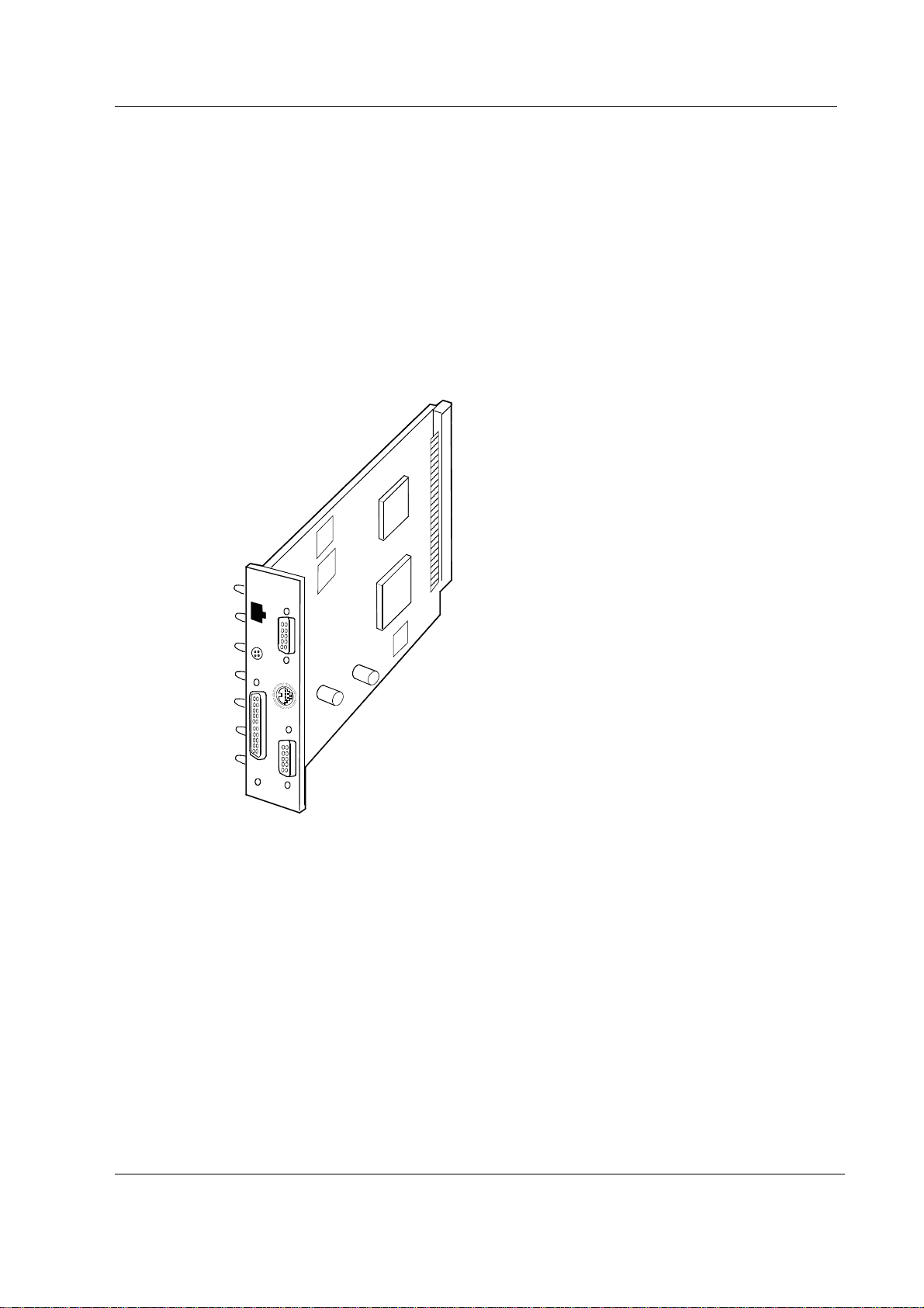
Datex-Ohmeda S/5 UPI4NET board, B-UPI4NET integrates the UPI board and the Network Board,
B-NET. Datex-Ohmeda S/5 UPI4 board, B-UPI4 is the same board as UPI4NET except it does not
contain network related components.
The UPI4NET and UPI4 boards provide interfaces for example for a computer, parallel printer and
Device Interface Solution (DIS). In addition, the boards have two digital output signals and two
analog output signals for other interfaces.
The use of UPI4NET or UPI4 board requires S/5 Anesthesia or Critical Care main software.
S/5 UPI(NET) Board, B-UPI4(NET)
Figure 1 UPINET Board, B-UPI4NET
1
Document No. 800 1022-1
Page 6

Datex-Ohmeda S/5 AM and S/5 CCM
1 TECHNICAL SPECIFICATIONS
1.1 General
• Voltages:
+5 V, 500 mA
+15 VD, 50 mA + DIS power supply
• Voltage and temperature measurement
1.2 UPI
• Supports RS485 500 kbps module bus communication
• Supports RS422 500 kbps Device Interface Solution (DIS) bus communication
• Printer port (LPT)
• RS232 level communication driven by B-CPU4
• Analog signals:
− Direct ECG
− Pressure Out
• • Digital signals:
− Defibrillation Synchronization
− Nurse Call
1.3 NET (Ethernet)
• Meets IEEE802.3 specifications (10BASE-T)
• Hospital grade approved data transformer
• Coding element interface
2
Document No. 800 1022-1
Page 7
2 FUNCTIONAL DESCRIPTION
2.1 General
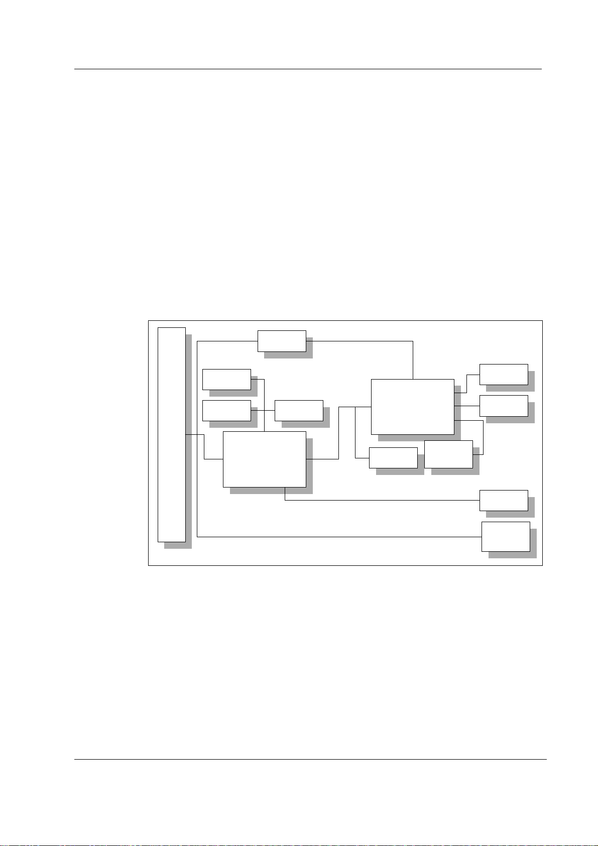
2.1.1 UPI section
The UPI section functions as a general I/O-board. It performs I/O duties assigned to it by the CPU
board. The main processor in the CPU board and the processor in the UPI section communicate
through a dual-port memory which is located on the UPI4(NET) board.
Functional blocks
The UPI section contains the external bus interface, a processor, program- and dual-port memories
and I/O-block.
S5 module bus
S/5 UPI(NET) Board, B-UPI4(NET)
S5 CPU BUS (X1 96-pin)
Figure 2 UPI section block diagram
External bus interface
The UPI section is connected to the CPU mother board. The following signals pass on between the
UPI section and CPU mother board: data bus, address bus, reset, read and write signals, and other
related signals.
JTAG
PLD EPROM
PLD
UPI
ID EEPROM
RAM
UPI CPU
Temperature
and voltage
measuremants
DIS bus
X5
SyncOut
X7
LPT-port
X3
RS232
Serial bus
X8
Processor
The processor in the UPI section is an H8S/2655, which functions at 16 MHz frequency.
3
Document No. 800 1022-1
Page 8
Datex-Ohmeda S/5 AM and S/5 CCM
RS232 serial bus interfaces
RS232 serial bus is connected to the connector X8. That serial channel is driven by the CPU board.
Only the RS232 buffer and some filtering components are located in the UPI4(NET) board.
RS485 module bus interface
RS485 half-duplex communication bus for modules. Communication speed rate is 500 kbps.
RS422 DIS bus interface
RS422 full-duplex communication bus for DIS modules. Communication speed rate is 500 kbps.
DIS interface includes DIS power supply that gives voltages +8 V (max 1A) and +15 VD (max 1A).
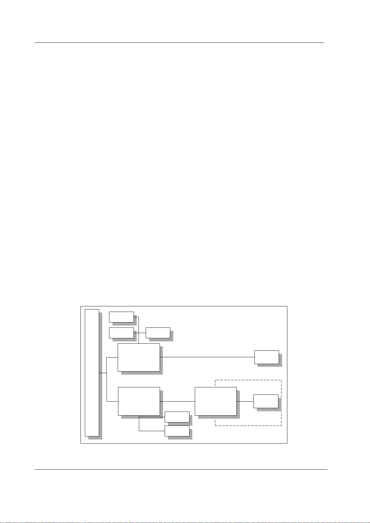
2.1.2 NET section
The NET section is illustrated in a block diagram shown in figure 3.
The network interface controller is basically the heart of the NET section. The interface controller
communicates with the CPU board through the controller registers to the RAM. During the startup
sequence controller loads its address and some initializations from EEPROM.
The network interface controller transmits data packets to the S/5 Network and receives data
packets from the network through the 10BASE-T transformer. The transformer filters and transforms
the data and also provides the isolation.
The Ethernet status LEDs indicate the status of the network communication. The status LEDs are
controlled by the network controller. The LEDs are not visible when the board is installed into the
monitor.
The PLD interfaces the coding element. The coding element contains information on the monitor
location. The network address is transmitted to the CPU board through the network controller and
the monitor location information is transmitted to the CPU board through PLD interface.
JTAG
UPI
ID EEPROM
Filtering &
Isolation transformer
Location ID
connector
X4
RJ45
connector
X6
S5 CPU BUS (X1 96-p in)
PLD EPROM
PLD
Ethernet Controller
4
Document No. 800 1022-1
RAM
Isolation
EEPROM
Figure 3 NET section block diagram
Page 9
2.2 Ethernet interfaces
The data transformer is designed by Datex-Ohmeda and it is hospital grade approved.
Adapter’s 10BASE-T is a interface with 7-pole butterworth low-pass filters on the unisolated side of
the transformer. On the isolated side there is a common mode choke for both transmitting and
receiving lines.
There are also three LEDs on the board, which are not seen from the outside, indicating the
following things:
- activity in Ethernet H1 Green
- collision detection H3 Yellow
- good link in 10BASE-T interface H2 Green
The activity LED (H1) flashes when communication packets are detected in the S/5 Network. The
collision detection LED (H3) indicates a packet collision on the network. The collision detection
LED should flash only occasionally, otherwise there may be a physical layer problem. The good link
LED (H2) indicates whether or not the communication link to the HUB is functional. The good link
LED should always be lit.
S/5 UPI(NET) Board, B-UPI4(NET)
2.3 Connectors and signals
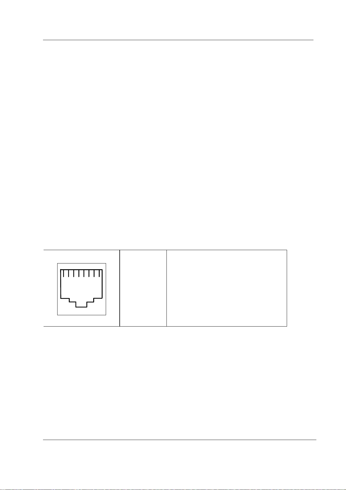
2.3.1 Ethernet Network Interface Network Connector, X6
RJ45 connector Pin Signal
123
45
1
2
6
78
3
4
5
6
7
8
Tx +
Tx Rx +
N/C
N/C
Rx N/C
N/C
Document No. 800 1022-1
5
Page 10

Datex-Ohmeda S/5 AM and S/5 CCM
9
2.3.2 Network coding element interface
Coding element connector, X4
9 pin female D-connector
1
6
Direct ECG (pin 7)
− Delay (max.): 15 ms
− Gain ECG (in)/ECG(out): 1 mV/1V
NOTE: The direct ECG out signal is not available with the Central Unit, F-CU8 rev. 01, and with
modules M-ESTP rev. 01, M-EST rev. 00 and M-ETP rev. 00.
Nurse Call (pin 8)
The nurse call signal is generated by the red, yellow and white alarms. When activated, the signal is
set to the high state and remains at the high state until the alarm situation is over or the SILENCE
ALARM key is pressed. The high state range is from 2.8 to 5 V, while the low state range is from 0 to
0.8 V.
Pin Signal
1
2
5
3
9
4
5
6
7
8
9
IDCS1 (chip select)
IDCL (clock)
IDDI (data in)
IDDO (data out)
IDPE (protect enable)
+5Vdc
Direct ECG
Nurse call
gnd
If the output signals are used simultaneously with the coding element, the B-UPINET Y-cable, order
number 889308, is recommended to be used.
2.3.3 RS232 serial data interface
RS232 Serial data connector X8
pin male D-connector
1
6
5
9
Pin Signal
1
2
3
4
5
6
7
8
9
GND
RxD
TxD
NC
GND
N/C
RTS
CTS
N/C
6
Document No. 800 1022-1
Page 11

2.3.4 DIS interface (RS422)
DIS connector, X5
S/5 UPI(NET) Board, B-UPI4(NET)
10 -pin female connector
87
654
2
3
1
Pin Signal
1
2
3
4
5
6
7
8
DIS_out +
DIS_out 15V_DIS
GND
8V_DIS
GND
DIS_in +
DIS_in -
The Invasive pressure output signal is 1 V/100 mmHg, originally ranging from 0 to 300 mmHg, and with a delay of
approximately 25 ms. The signal requires an input impedance of 100 kΩ.
2.3.5 Synchronization interface
Synchronization connector , X7
4 pin female connector
1
4
23
Pin Signal
1
2
3
4
GND
Def_Sync
Direct ECG
Pressure Out
Direct ECG (PIN 3):
− Delay (max.): 15 ms
− Gain ECG (in)/ECG(out): 1 mV/1V
NOTE: The direct ECG out signal is not available with the Central Unit, F-CU8 rev. 01, and with
modules M-ESTP rev. 01, M-EST rev. 00 and M-ETP rev. 00.
Pressure out (PIN 4):
− P1 from hemodynamic module
The Invasive pressure output signal is 1 V/100 mmHg, originally ranging from 0 to 300
mmHg, and with a delay of approximately 25 ms. The signal requires an input impedance
of 100 kΩ.
Document No. 800 1022-1
7
Page 12

Datex-Ohmeda S/5 AM and S/5 CCM
Printer interface
Standard printer connector , X3
25 pin female D-connector
Pin Signal
1
2
3
4
5
6
7
8
9
10
11
12
13
14
15
16
17
18
19
20
21
22
23
24
25
Data_clk
Data0
Data1
Data2
Data3
Data4
Data5
Data6
Data7
N/C
Printer busy
Paper end
N/C
N/C
Error/
N/C
GND
GND
GND
GND
GND
GND
GND
GND
GND
8
Document No. 800 1022-1
Page 13

2.3.6 Connection to the S/5 bus
S/5 CPU bus connector X1
AB C
1
2
3
4
5
6
7
8
9
10
11
12
13
14
15
16
17
18
19
20
21
22
23
24
25
26
27
28
29
30
31
32
+15 V AGND DGND
-15 V BALE DGND
SA0 SA1 DGND
SA2 SA3 RESET_RS485
SA4 SA5 -RESET_RS485
SA6 SA7 DATA_RS485
SA8 SA9 -DATA_RS485
SA10 SA11 TXDD_RS232
SA12 SA13 RXDD_RS232
SA14 SA15 Direct_ECG_PWM
SA16 SA17 BIT1IN
SA18 SA19 TXDC
SA20 SA21 RXDC
SA22 SA23 RTSC
-SMEMR -SMEMW CTSC
-IOR -IOW TXDB
CLK -RESET RXDB
-IOCHRDY IRQ10 RTSB
N/C_1 IRQ11 CTSB
N/C_2 IRQ12 TXDA
-SBHE IRQ15 RXDA
SD0 SD1 RTSA
SD2 SD3 CTSA
SD4 SD5 LOUDSPEAKER
SD6 SD7 +5 V
SD8 SD9 +5 V
SD10 SD11 +5 V
SD12 SD13 +5 V
SD14 SD15 ON/STBY
+15 VD -RESET_CPU +5 V_CPU
+15 VD +32 VD REFRESH_WD
GNDD GNDD POWER_FAIL
S/5 UPI(NET) Board, B-UPI4(NET)
Document No. 800 1022-1
9
Page 14

Datex-Ohmeda S/5 AM and S/5 CCM
3 SERVICE PROCEDURES
Due to the nature of the UPI4(NET) board, field service is limited only for troubleshooting. Faulty
UPI4(NET) boards are returned to Datex-Ohmeda for repair.
Datex-Ohmeda is always available for service advice. Please provide the unit serial number, full
type designation and a detailed description of the fault.
CAUTION Only trained personnel with appropriate tools and equipment are allowed to
perform the tests and repairs outlined in this section. Unauthorized service may void
warranty of the unit.
3.1 Service check for the NET section
These instructions include complete procedures for a service check for the UPI4(NET) board. The
service check is recommended to be performed after any service repair. However, the service
check procedures can also be used for determining possible failures.
The procedures should be performed in ascending order.
The instructions include a check form
procedures.
The mark
the procedure.
The procedures are designed for monitors with S/5 monitor software of revision 01. However, most
of the procedures also apply to monitors, which contain some other monitor software
type/revision.
? in the instructions means that the check form should be signed after performing
(Appendix
A) which should be filled in when performing the
3.1.1 Recommended tools
Tool Order No. Notes
Command Bar / Command Board
M-NE(12)STPR/M-ESTPR/M-ESTP
Datex-Ohmeda gas monitor e.g. Capnomac Ultima
UPI Interface cable 887245
Datex-Ohmeda Network only for UPI4NET
Mon-Net cable only for UPI4NET
Patient simulator
Screwdriver
10
Document No. 800 1022-1
Page 15

S/5 UPI(NET) Board, B-UPI4(NET)
General
Make sure the monitor is switched to standby. Press the service reset -switch at back of the power supply unit at least
for five seconds. Disconnect the Mon-Net cable, Identification plug and Network cable extension from the UPI4NET
board, if installed.
Detach all PC boards from the right side of the UPI4(NET) board. Detach the UPI4(NET) board carefully by pulling it
from the connector X3 (25 pin female D-connector).
NOTE: The UPI4(NET) board contains components on both sides of the PC board. Therefore, installation of UPI4(NET)
board should be done with extra care.
NOTE: Wear a static control wrist strap when handling PC boards. Electrostatic discharge may damage components
on the board.
1. Check that the UPI4(NET) board connectors are intact and all connector cables are
connected properly on the PC board.
?
2. Check that none of the PC board components is damaged (on both sides) and the IC on a
socket is attached properly.
?
3. Check that all block screws for cables are in place and are tightened properly. Check also
that their threads are intact.
?
4. Check that the grounding plate under the PC board rear panel is attached properly and is
not bent.
?
UPI functions
Re-install the UPI4(NET) board together with the other detached PC boards carefully. Do not connected any cables to
the UPI4(NET) board at this point. Switch the monitor on. Make sure that M-NE(12)STPR/M-ESTPR/M-ESTP module
is installed. Connect a patient simulator to the module.
5. Check that the displayed parameter data and waveforms are reasonable.
?
6. Enter the service menu.
Monitor Setup -
Frame
-
Power Supply
Check that the displayed voltage and temperature values (measured by the UPI4(NET)
board) are reasonable.
Install/Service
(password 16-4-34) -
Service
(password 26-23-8) –
?
11
Document No. 800 1022-1
Page 16

Datex-Ohmeda S/5 AM and S/5 CCM
7. Test UPI4(NET) board watchdog function.
Set / Test – WD by UPIy
Perform the test and check that monitoring continues normally.
?
8. Switch the monitor to standby. Connect a Datex-Ohmeda gas monitor to the UPI4(NET)
board using the UPI Interface cable P/N 887245 (44-pin connector is left disconnected).
Switch both monitors on and set the interface according to the interfaced gas monitor:
Monitor Setup -
Spiro -SpO2
Check that numerical data regarding the interfaced parameters appears onto the monitor
screen.
?
NET functions
9. Check the Network cable extension:
−the cable is intact
−the cable connectors are clean and intact
−the claw for locking the cable to the Network Board is intact
Connect the Network cable extension to the UPI4NET board.
Install/Service
(password 16-4-34)
- Installation - Interfacing -Gases/
?
10. Check that the Mon-Net cable connector and the Identification plug are clean and intact,
then connect them to the UPI4NET board.
Check that the monitor connects onto the Datex-Ohmeda Network, i.e. the network symbol
appears under the clock on the upper right hand corner of the screen.
A message regarding the connected Datex-Ohmeda Central should appear into the
message field of the screen.
NOTE: If the network symbol does not appear, check the status of the network.
?
11. Enter the service menu.
Frame- Network
Take down the monitor’s Ethernet address that is shown beside the text “Address”.
?
12. Check that the service menu counters for the received (“In”) and transmitted (“Out”) data
are updated frequently.
?
13. Check that the counters for data errors (“CRC”, “Frame”, “Transm.”) are stable.
NOTE: The counters may show values higher than 0. However, if any of the values is
increasing continuously, it indicates a problem.
12
Document No. 800 1022-1
?
Page 17

General
S/5 UPI(NET) Board, B-UPI4(NET)
14. Check that the counters for hardware errors (“Intern.”, “Missed”, “FIFO”, “Overrun”)
show all 0. If any of the counters show a value higher than 0, replace the UPI4NET board.
?
15. Disconnect the Mon-Net cable from the Network cable extension. Check that the message
“Network down:” appears into the message field within 30 seconds. Reconnect the MonNet cable and check that the monitor connects onto the network again.
?
16. Switch the monitor to standby. Disconnect the Identification plug from the UPI4NET board.
Switch the monitor back on and check that the message “Check network connectors”
appears into the message field. Reconnect the Identification plug and check that the
monitor connects onto the network.
?
17. Perform electrical safety check and leakage current test.
18. Check that the Network Board functions normally after the performed electrical safety
check.
• Fill in all necessary documents.
13
Document No. 800 1022-1
Page 18

Datex-Ohmeda S/5 AM and S/5 CCM
4 TROUBLESHOOTING
4.1 Troubleshooting for the NET section
Symptom at the monitor end Problem at Explanation/correction
Monitor does not connect to the
network.
Monitor connects to the network, but
disconnects unexpectedly (‘Network
connection down’ message on the
monitor screen).
Patch panel Patch cable not connected to HUB or to
panel.
Patch cable Patch cable or connector defective.
HUB not connected to power supply.
HUB port closed due to physical layer
problems.
HUB port temporarily closed and reopened
due to physical layer problems.
Hubs not properly connected to each other.
Monitor-Network cable Cable not properly connected to the
wallplate or to the monitor.
Monitor-Network cable Cable or connector defective.
UPI4NET board The UPI4NET board is defective. The board
cannot be used. See network service page
for details.
‘Network EEPROM Error’ message
shows on the monitor screen
‘Check network connectors’
message shows on the monitor
screen
14
Document No. 800 1022-1
UPI4NET board EEPROM The EEPROM of the UPI4NET board is
defective or uninitialized. The board cannot
be used. See network service page for
details.
Identification plug There is no Identification plug attached to
the monitor.
The identification plug is defective or
uninitialized. The plug cannot be used.
UPI4NET board EEPROM The EEPROM of the UPI4NET board is
defective or uninitialized. The board cannot
be used. See Network service page for
details.
Monitor-Network cable Cable not properly connected to the
wallplate or to the monitor.
Page 19

S/5 UPI(NET) Board, B-UPI4(NET)
Symptom at the monitor end Problem at Explanation/correction
Cable or connector defective.
Identification plug There is no identification plug properly
attached to the monitor.
The Identification plug is defective or
uninitialized. The plug cannot be used. See
network service page for details.
‘Network board error’ message
shows on the monitor screen
UPI4NET board The UPI4NET board is defective. The board
cannot be used. See network service page
for details.
UPI4NET board EEPROM The EEPROM of the UPI4NET board is
defective or uninitialized. The board cannot
be used. See network service page for
details.
Other Site View shows no waveforms No waveforms are set up for
Monitor-to-Monitor
Run S/5 Network Setup to verify current
Monitor-to-Monitor communication setup.
communication
Network printing fails Print server is busy Network manager's print server is busy at
the moment and cannot take more print
jobs. Try again after 15 seconds.
Print queue is full There are too many unprinted documents
waiting in the print queue. Check the
printer, as it is not operating properly.
Printer is off-line Printer cable is loose, printer is out of
paper, there is paper jam or the printer is
simply switched to off-line state.
Record keeper menus are blank There are no menus for the
record keeper
Run S/5 Network Setup to verify the current
set up.
15
Document No. 800 1022-1
Page 20

Datex-Ohmeda S/5 AM and S/5 CCM
4.2 Troubleshooting for the UPI section
Central Unit faulty
Check mains fuses.
Does Central Unit work?
No
Check fuses on Power
Supply Board.
Does Central Unit work?
No
Disconnect mains power cord.
Remove all plug-in modules.
Disconnect Airway module.
Disconnect Command board.
Connect mains power cord and
turn power on by sh orting pins
13 (GND) and 20 (ON/STBY) at
Gas interface board conne cto r.
Yes
Rem ove Powe r supply unit and
turn it on by shorting pins a14
(ON/STBY) and a18 (GND). See
chapter 2.4.1 connector X3 .
Is fan
running?
No
Is fan
running?
No
Are
power supply
voltages
OK?*
No
Power supply board/unit
faulty. Replace it.
Yes
Yes
CPU mother board or Gas
interface board faulty.
Check continuitie s of ground
and ON/STBY line through to
Comm and board.
Digital s e c tion faulty. Go to
"Digital section troubleshooting
chart".
* see 2.4.1 connector x3
5V
5V CPU
+15 V
- 15 V
+32 V
.
16
Document No. 800 1022-1
Page 21

5 SERVICE MENU
S/5 UPI(NET) Board, B-UPI4(NET)
To enter the
1. Press the Monitor Setup key.
2. Select
3. Select
4. Select
Network Service Menu
Install/Service
Service
(password 26-23-8).
Frame- Network
:
(password 16-4-34).
.
17
Document No. 800 1022-1
Page 22

Datex-Ohmeda S/5 AM and S/5 CCM
5.1 Network menu
The Communication view shows the general status of the
network communication. The four Network status menus
are related to the four subnet id:s that the monitor is
connected to. The DRI Level is for setting the monitor's
network communication. The network communication is
set according to the used network software (e.g. S-
CNET01). The Connections field represents the network
status menus respectively. The three first connections are
reserved permanently for Datex-Ohmeda Central and the
fourth is reserved for another subnet id, e.g. DatexOhmeda CS/3 Arrhytmia Workstation. The service data
related to the communication view is described in the
table below.
Value Usage Notes
Received packets (Statistics In/Packets) Total number of received packets since last cold start.
Transmitted packets (Statistics Out/Packets) Total number of transmitted packets since last cold start.
Received bytes (Statistics In/Bytes) Total number of received bytes since last cold start
Transmitted bytes (Statistics In/Bytes) Total number of transmitted bytes since last cold start
CRC errors (CRC) Number of received packets with incorrect checksum
Frame errors (Frame) Number of received packets with incorrect frame structure Refers to physical layer
problems. An
erroneous packet often
has both frame and
CRC error.
Transmission errors (Transm.) Number or errors in packet Transmission
Internal errors (Intern.) Internal error of the network Board. Must always be 0.
Missed packets (Missed) Number of received packets Lost due to overload Must always be 0
FIFO errors (FIFO) Internal error of the network Board Must always be 0
Overrun errors (Overrun) Practically same as above Must always be 0
Location ID Monitor’s location given at the Setup
Address Monitor’s ethernet address
Connections Names of subnet id:s connected
18
Document No. 800 1022-1
Page 23

5.1.1 Network status
The network view gives more accurate information of the
different subnet id:s connected. All four
menus have similar structure. The number of different
packets transmitted and received by the monitor are
shown in the columns below Tx and Rx. The packet types
are described in the table below.
Waveforms Waveform data
Phys. data Physiological numerical data
Alarms Alarms, alarm profiles and alarm limits
Link mgmt Network management messages
Record K Record Keeper data
MonToMon Monitor-to-monitor communication
related data
Printer Printing data and control messages
File Op. File operation messages, saving and
loading of cases
Service Maintenance and service
Modes User mode data
Indics. Remote indications sent to monitor
RemoteEv Remote events
Data server Packets of the data server (Arrhythmia
Workstation)
Packets total Total number of packets sent/received
Bytes total Total number of bytes sent/received
Network status
S/5 UPI(NET) Board, B-UPI4(NET)
5.2 Communication
A service menu for showing information about internal RS485 and external RS-232 communication.
Module Bus (RS485) view shows information related to
the module bus.
UPI ints shows the number how many times the CPU
board has sent an interrupt to UPI board. The running
number should rise at a frequency of at least 100 Hz. If
the numbers don't rise there is trouble with the interrupt
line between CPU board and UPI board or with the boards
themselves.
The 10 ms tick shows how many 10 ms intervals the UPI
microprocessor has been on after last UPI reset. The UPI
microprocessor counts the 10 ms intervals. The number
must be running all the time at the frequency of 100 Hz. If
the number doesn't rise, the problem is in the UPI board.
Serial I/O (RS-232) view shows information about the
communication through the UPI board RS232 serial
connector X8.
Interface status shows whether the interface through the
connector is OPENED, ACTIVE or CLOSED. Opened
indicates that the hardware and software for the interface
is running but there is no connection or that there have
been errors in using the interface. Active indicates that the
interface is operating normally. Closed indicates that the
necessary hardware is not present.
Statistics In/Out show the numbers of received and
transmitted data packets and data bytes.
Rx errors show the number of received erroneous data
packets.
19
Document No. 800 1022-1
Page 24

Datex-Ohmeda S/5 AM and S/5 CCM
6 SPARE PARTS
UPI4NET Board, B-UPI4NET rev.00, UPI4 Board, B-UPI 4 rev.00
Item description Order No.
Block screw for cables 546096
20
Document No. 800 1022-1
Page 25

7 EARLIER REVISIONS
This manual supports only UPI4 Board, B-UPI4 and UPI4NET Board, B-UPI4NET.
See information related to earlier revisions of UPI board from main manual 896624 and slot
895704-1.
S/5 UPI(NET) Board, B-UPI4(NET)
21
Document No. 800 1022-1
Page 26

Datex-Ohmeda S/5 AM and S/5 CCM
22
Document No. 800 1022-1
Page 27

Appendix A, S/5 UPI(NET) Board, B-UPI4(NET)
APPENDIX A
23
Document No. 800 1022-1
Page 28

Datex-Ohmeda S/5 AM and S/5 CCM
24
Document No. 800 1022-1
Page 29

Appendix A, Service check form, S/5 UPI(NET) Board, B-UPI4(NET)
SERVICE CHECK FORM
UPI4(NET) Board, B-UPI4(NET)
Customer
Service
Service engineer Date
OK = Test OK N.A. = Test not applicable Fail = Test Failed
General
1. UPI4(NET) board
connectors
3. Screws 4. Grounding plate
Notes
UPI functions
5. Parameter data and
waveforms
7. Watchdog 8. Data of interfaced
Notes
OK N.A. Fail OK N.A. Fail
Board type S/N
2. PC board components
and IC attachment
6. Voltage and
temperature
parameters
NET funtions
9. Network cable
extension
11. Ethernet address
12. “In “, “Out” data
counters
14. Hardware error
counters
16. Recognition of ID-plug
Notes
10. Mon-Net cable and
ID-plug
Address
13. Data error counters
15. Regocnition of
disconnection
A-1(2)
Document No. 800 1022-1
Page 30

Datex-Ohmeda S/5 AM and S/5 CCM
General
17. Electrical safety check 18. Functioning after
electrical safety check
Notes
Notes
Used Spare Parts
Signature
A-2(2)
Document No. 800 1022-1
 Loading...