

Page 1

Datex-Ohmeda
S/5™ Interface Board, B-INT (Rev. 01)
Technical Reference Manual
Datex-Ohmeda Inc.
3030 Ohmeda Drive
53707-7550 MADISON, WIS
USA
Tel. +1-608-221 1551, Fax +1-608-222 9147
www.us.datex-ohmeda.com
All specifications are subject to change without notice.
Document No. 8001006-1
June 2001
Datex-Ohmeda Division,
Instrumentarium Corp.
P.O. Box 900, FIN-00031
DATEX-OHMEDA, FINLAND
Tel. +358 10 394 11 Fax +358 9 146 3310
www.datex-ohmeda.com
Instrumentarium Corp. All rights reserved.
Page 2

Page 3

Table of contents
TABLE OF CONTENTS
Interface Board, B-INT (Rev. 01)
TABLE OF CONTENTS i
Introduction 1
1 Specifications 2
1.1 Serial I/O definitions.................................................................................................................................2
1.2 Analog definitions.....................................................................................................................................2
2 Functional Description 3
2.1 Main components.....................................................................................................................................4
2.2 Connectors and signals.............................................................................................................................6
2.2.1 Bus connectors................................................................................................................................6
2.2.2 Serial connectors.............................................................................................................................8
2.2.3 Serial/analog connectors.................................................................................................................9
3 Service Procedures 10
3.1 General service information.....................................................................................................................10
3.2 Service check.........................................................................................................................................11
3.2.1 Recommended tools......................................................................................................................11
4 Troubleshooting 16
4.1 Troubleshooting chart.............................................................................................................................16
5Service MENU 17
5.1 Interface menu.......................................................................................................................................18
6 Spare Parts 20
6.1 Interface Board, B-INT.............................................................................................................................20
7 Earlier Revisions 21
APPENDIX A
23
Service check FORM A-1
Document No. 8001006-1
i
Page 4

Datex-Ohmeda S/5 monitors
ii
Document No. 8001006-1
Page 5
INTRODUCTION
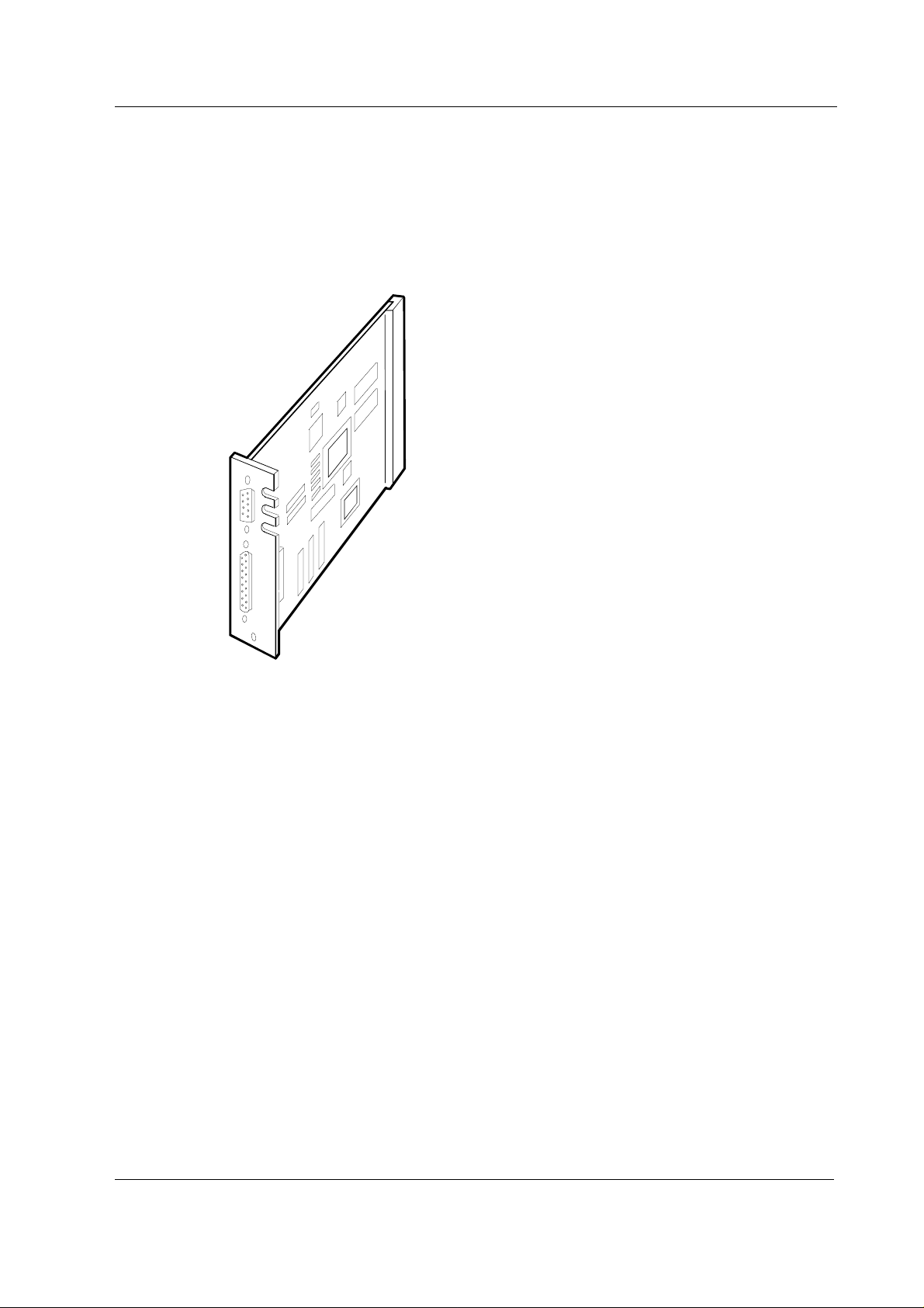
The Interface Board, B-INT, provides an interface between the S/5 Anesthesia Monitor or the S/5
Critical Care Monitor and other monitors. It also provides a connection between the Central Unit, FCU8, and the Airway Module, G-xxxx.
Interface Board, B-INT
Figure 1 Interface Board, B-INT
NOTE: The Interface Board, B-INT, and Interface Module, M-INT, cannot be used simultaneously in
the same monitor.
Document No. 8001006-1
1
Page 6

Datex-Ohmeda S/5 monitors
1 SPECIFICATIONS
1.1 Serial I/O definitions
• RS-232 buffered (channels 1-4)
• All standard baud rates are possible from 300 to 115200
• Each interfaced device has fixed baud rate.
1.2 Analog definitions
• There are four analog inputs available on channel 1 and four on channel 2.
• All analog inputs are op-amp buffered, with an input impedance of 1 MΩ. Each analog
input is also equipped with a 1 MΩ pull-down resistor to -12 V for NC detection.
• Sampling rate: 10 ms/sample/channel
• Input range: -10 V...+10 V
• Resolution: 10 bits → 1024 voltage levels in input range
2
Document No. 8001006-1
Page 7
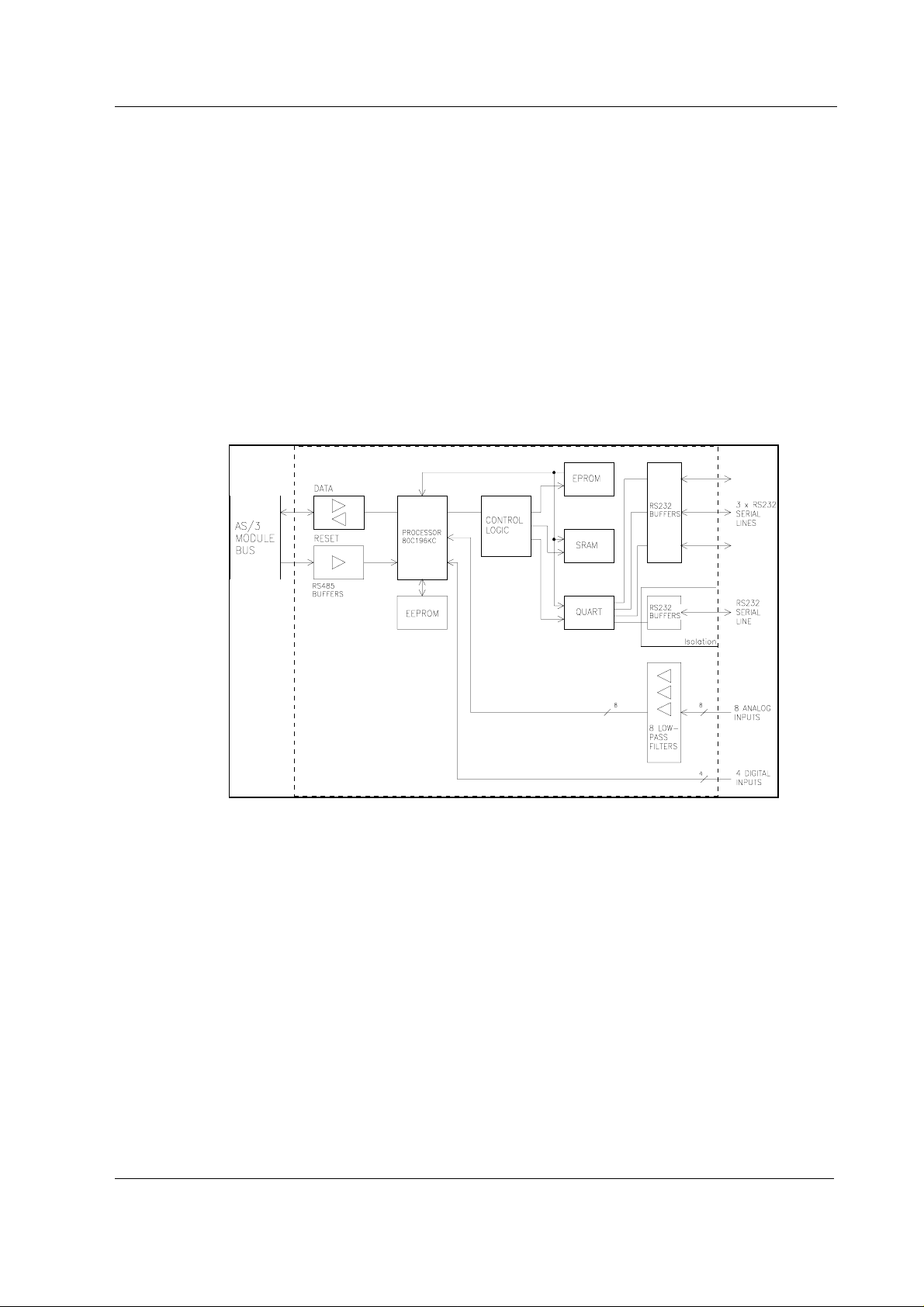
2 FUNCTIONAL DESCRIPTION
The Interface Board, B-INT, detects and identifies external monitors connected to the S/5
anesthesia or critical care monitoring system. Identification is made by a serial data string sent by
the external monitor.
On the front panel of the board there is a 25-pin and a 9-pin D-connector, which are used for
sending/receiving digital serial data. The 25-pin D-connector is used for connecting the Airway
Module (as the Gas Interface Board is removed when the Interface Board, B-INT is installed).
On the surface of the circuit board there are three pin row connectors, one for digital data and two
for digital and analog data. If digital and analog real time waveforms are required, the external
monitor can be connected to the serial/analog connectors (X7 and X8) using additional interface
connector cables.
Interface Board, B-INT
Figure 2 Interface Board, B-INT, block diagram
3
Document No. 8001006-1
Page 8

Datex-Ohmeda S/5 monitors
2.1 Main components
The Interface Board contains an 80C196KC16 CPU.
External connections
The connectors on the board are:
• 96-pin E-connector for the CPU mother board (X1)
• 25-pin D-connector for an Airway Module (X3).
• 9-pin D-connector for RS-232 level isolated serial communications (X2). No analog inputs
available.
In addition, three pin-row connectors on the circuit board make the following connections possible
using an interface connector cable:
• RS-232 level serial and analog connectors for all interfaces (X7, X8).
• RS-232 level serial digital connector (X9).
X3 and X9 connectors can be used to interface waveforms from Dräger Cato and Cicero external
monitors.
The Interface Board is connected to the Central Unit module bus through the CPU mother board.
Serial communication signals for transmitting (TxD) and receiving (RxD) data are sent to the
microcontroller ports. The direction of the communication is controlled by REC/SND/ signal at the
buffers. The RESET/ signal always resets the communication to the RxD state.
Reset
The Interface Board is reset when the Central Unit is reset (MAIN/RESET/) or when the module bus
is reset (RESET_RS485).
The RESET/ signal is sent to an address decoding GAL circuit, from which it goes to the
microcontroller as RESET/Z. When the RESET/ is active (low), the RESET/Z also goes low and
resets the microcontroller.
Serial communication channels
A QUART is used to provide four serial communication channels (TxD, RxD). The microcontroller is
able to reset the QUART at any time by pu lling the QRESET signal high. The QUART is also reset
when the microcontroller is reset; the microcontroller pulls all the port 1 signals high when it resets.
Memories
There are static RAM, EPROM, EEPROM memories and an address decoding GAL unit on the
Interface Board.
4
Document No. 8001006-1
The microcontroller communicates with the EEPROM in serial mode.
Page 9

Digital inputs
Analog inputs
Fuse
Interface Board, B-INT
Four digital inputs are connected to connector X9 on the Interface Board. They pass through to the
microcontroller's high speed pins (DIGBUS). The digital inputs have an overvoltage protection and
a pull-up circuit.
Eight analog inputs are connected to connectors X7 and X8. They pass through EMI filters and lowpass filters to the microprocessor port 0.
A 4 A fuse is installed on the Interface Board for the +24/+32 Vdirty input supply. This voltage is
not used on the board but passed through to the 25-pin D-connector for Airway Module use.
Document No. 8001006-1
5
Page 10

Datex-Ohmeda S/5 monitors
2.2 Connectors and signals
X2
X3
2.2.1 Bus connectors
Module bus connector (X1)
1 +15 V AGND DGND
2 -15 V BALE DGND
3 SA0 SA1 DGND
4 SA2 SA3 RESET_RS485
5 SA4 SA5 -RESET_RS485
6 SA6 SA7 DATA_RS485
7 SA8 SA9 -DATA_RS485
8 SA10 S A11 TXDD_RS232
9 SA12 S A13 RXDD_RS232
10 SA14 SA15 BIT0IN
11 SA16 SA17 BIT1IN
12 SA18 SA19 TXDC
13 SA20 SA21 RXDC
14 SA22 SA23 RTSC
15 -SMEMR -SMEMW CTSC
16 -IOR -IOW TXDB
17 CLK -RESET RXDB
18 -IOCHRDY IRQ10 RTSB
19 N/C_1 IRQ11 CTSB
20 N/C_2 IRQ12 TXDA
21 -SBHE IRQ15 RXDA
22 SD0 SD1 RTSA
23 SD2 SD3 CTSA
24 SD4 SD5 LOUDSPEAKER
25 SD6 SD7 +5 V
26 SD8 SD9 +5 V
27 SD10 SD11 +5 V
28 SD12 SD13 +5 V
29 SD14 SD15 ON/STBY
30 +15 VD -RESET_CPU +5 V_CPU
31 +15 VD +32 VD REFRESH_WD
32 GNDD GNDD POWER_FAIL
X1
X7
X8
X9
ab c
6
Document No. 8001006-1
Page 11

Interface Board, B-INT
13
25
1
14
Airway Module bus connector (X3)
Pin No I/O Signal
1 O RESET_RS485
2 O -15 VDC
3 O +15 VDIRTY
4 O +15 VDC
5 I/O -DATA_RS485
6 I/O DATA_RS485
7 Ground & Shield
8 O -RESET_RS485
9 O CTSB
10 I RTSB
11 O RXDB
12 I TXDB
13 Ground & Shield
14 O +32 VDIRTY
15 O GroundDIRTY
16 O CTSC
17 I RTSC
18 O RXDC
19 I TXDC
20 ON/STANDBY
21 BIT0IN
22 RXDD_RS232
23 TXDD_RS232
24 O +5 VDC
25 O +5 VDC
Document No. 8001006-1
7
Page 12

Datex-Ohmeda S/5 monitors
2.2.2 Serial connectors
Serial connector (X2)
Pin No I/O Signal
1N/C
2 I RXD RS
3OTXD RS
4 O +5 V
5 O GND
6N/C
7 O RTS RS
8 I CTS RS
9N/C
Serial Connector (X9) CH 4 (non-floating, off-board)
Pin No Definition
1 D0 digital input
2RXD
3TXD
4 D1 digital input
5 GND
6 D2 digital input
7RTS
8CTS
9 D3 digital input
8
Document No. 8001006-1
Page 13

2.2.3 Serial/analog connectors
Serial/analog connector (X8) CH 1 (non-floating, off-board)
Pin No Definition
1 A0 analog input
2RXD
3TXD
4 A1 analog input
5 GND
6 A2 analog input
7RTS
8CTS
9 A3 analog input
Serial/analog connector (X7) CH 2 (non-floating, off-board)
Pin No Definition
1 A4 analog input
2RXD
3TXD
4 A5 analog input
5 GND
6 A6 analog input
7RTS
8CTS
9 A7 analog input
Interface Board, B-INT
Power test connector (X4)
Pin No Signal
1 +5 Vref
2 +5 V
3 +12 V
4 DGND
5 -12 V
6NC
Analog test connector
This connector is for factory tests only.
Document No. 8001006-1
9
Page 14

Datex-Ohmeda S/5 monitors
3 SERVICE PROCEDURES
3.1 General service information
A faulty Interface Board, B-INT, should be returned to Datex-Ohmeda for repair.
Datex-Ohmeda is always available for service advice. Please provide the unit serial number, full
type designation, and a detailed description of the fault.
CAUTION Only trained personnel with appropriate equipment should perform the tests and
repairs outlined in this section. Unauthorized service may void warranty of the unit.
10
Document No. 8001006-1
Page 15

3.2 Service check
These instructions include complete procedures for a service check. The service check is
recommended to be performed after any service repair. However, the service check procedures can
also be used for determining possible failures.
The procedures should be performed in ascending order.
Interface Board, B-INT
The instructions in clude a check form (
procedures.
The mark
the procedure.
The procedures are designed for monitors with S/5 monitor software of revision 01. However, most
of the procedures also apply to monitors, which contain some other monitor software
type/revision.
? in the instructions means that the check form should be signed after performing
Appendix A
) which should be filled in when performing the
3.2.1 Recommended tools
Tool Order No. Notes
Central Unit
Airway Module
Datex-Engstrom gas monitor with the SpO2 measurement e.g. ULT-S
INT Interface cable 892377
Interface connector cable 882353
Calibration gas
SpO2 probe
Screwdriver
• Make sure the S/5 monitor is turned to STBY.
• Press the Service Reset switch at back of the monitor power supply unit for at least five
seconds.
• Disconnect all external interface cables connected to the Interface Board, B-INT. Remove
the screws securing the Interface Board, B-INT to the Central Unit and remove the Interface
Board.
1. Check that the rear panel connectors are clean and intact. Check that the block screws for
cables are in place, are tightened properly and their threads are intact.
?
Document No. 8001006-1
11
Page 16

Datex-Ohmeda S/5 monitors
2. Check all interface connector cables (order code 882353) connected to the Interface
Board:
• the cables are intact a nd are properly attached with screws
• the cable connectors are clean and intact
• the block screws for cables are in place and are tightened properly
• the block screw threads are intact
?
3. Check the order of the interface connector cables, if connected:
• top: connector X8
• middle: connector X7
• bottom: connector X9
?
4. Check that the grounding plate under the rear panel is properly attached and is not bent.
NOTE: Older circuit boards may not include the grounding plate.
?
5. Check that the screws fastening the interface connector cable metal bracket to the Interface
Board rear panel are tightened properly.
?
6. Check that all socket mounted IC’s are inserted properly.
?
7. Check that the fuse and fuse holder are clean and intact. Check that the fuse is of the
correct rating (T4A).
?
• Connect the interface connector cable to connector X8 on the Interface Board, if not yet
connected. Re-install the Interface Board in the Central Unit and secure the board with two
screws.
• Connect the Airway Module using a gas interface cable to the Interface Board rear panel
connector X2. Connect the Datex-Engstrom gas monitor using the interface cable, order
code 892377 (use the gender changer) to Interface Board connector X8 (via the connected
interface connector cable).
• Turn both monitors on.
• Make sure the serial output mode of the Datex-Engstrom gas monitor being used is set to
NUMERIC.
• Configure the S/5 monitor screen so that all the required parameters are shown, for
example:
12
Document No. 8001006-1
Monitor Setup
- Screen 1 Setup - Waveform Fields - Field 5 - Pleth
Field 6 - CO
2
Page 17

8. Set the interface:
Interface Board, B-INT
Monitor Setup
Gases/Spiro - Module
and
Monitor Setup
Gases/Spiro - SpO
Check that menus NIBP and SvO2/C.O. are selectable from the menu.
- Install/Service
- Install/Service
- Module
2
(password 16-4-34)
(password 16-4-34)
- Installation - Interfacing -
- Installation - Interfacing -
?
9. Check that the waveform field for gases is shown on the S/5 monitor screen.
When the message “Calibrating gas sensor” disappears, feed calibration gas into the Airway
Module sampling line and check that the CO
correctly.
waveform and the gas numerics are shown
2
?
Set the Interface Board for the Datex-Engstrom gas monitor being used:
Monitor Setup
Gases/Spiro - XXX
and
Monitor Setup
Gases/Spiro - SpO
- Install/Service
- Install/Service
- XXX
2
(password 16-4-34)
(password 16-4-34)
- Installation - Interfacing -
- Installation - Interfacing -
XXX
= the used gas monitor
10. Enter t he service menu:
Monitor Setup
Take down the information regarding Interface Board software by selecting SCROLL VERS and
turning the ComWheel.
- Install/Service
(password 16-4-34)
- Service
(password 26-23-8)
?
11. Enter the B-INT service menu:
Parameters -More...-Interface
Check that the “Timeouts”, “Bad checksums” and “Bad c-s by mod” values are not
increasing faster than by 50 per second. Check that the B-INT memories have passed the
internal memory test, i.e. “RAM” and “ROM” state OK.
?
13
Document No. 8001006-1
Page 18

Datex-Ohmeda S/5 monitors
12. Check that the interfaced gas monitor is identified, i.e. the required waveform fields are
shown on the screen and the gas monitor type is shown correctly on the service menu.
Check that the communication state is “online”.
?
13. Select GASES from the B-INT service menu.
Check that “id:” states the correct monitor and interface type, “Active” states YES and
“Timeout” NO.
Check that the numeric values on the service menu are reasonable.
Simulate breathing by feeding calibration gas into the Datex-Engstrom gas monitor
sampling line and check that the values on the service menu correspond with the values on
the gas monitor screen.
Check that the values in the S/5 monitor gas waveform field are correct and a proper CO
waveform is shown.
Stop feeding calibration gas. Check that the message “Apnea” appears in the S/5 monitor
waveform field, and in the message field, if t he selected interface type is ULT/al.
?
14. Select SpO2 from the B-INT service menu.
Check that “id” states the correct monitor and interface type, “Active” states YES and
“Timeout” NO.
Check that “ProbeOff” shows 1 when no SpO
monitor. Connect the SpO
Attach the SpO
the values on the gas monitor screen.
Check that the values in the S/5 monitor pleth waveform field are correct and a proper pleth
waveform is shown.
Disconnect the SpO
waveform field, and “SpO
ULT/al.
probe to your finger and check that the values on the menu correspond with
2
probe and check that “NoProbe” shows 1.
2
probe. Check that the message “Probe off “ appears in S/5 monitor
2
probe off” appears in the message field, if the interface type is
2
probe is connected to the interfaced gas
2
2
14
Document No. 8001006-1
?
15. Turn the gas monitor off. Check that the messages “Interfaced Gas monitor removed” and
“Interfaced SpO
monitor removed” appear on the S/5 monitor screen.
2
?
Page 19

Interface Board, B-INT
16. Turn the monitor off. Connect the gas monitor with the interface cable, to Interface Board, BINT, connector X7 (via the interface connector cable). If necessary, remove the Interface
Board, B-INT, for relocating the interface connector cable.
Turn the monitors on and check that the necessary numerics and waveforms are still
interfaced, together with the necessary alarms, if the interface type is ULT/al.
?
17. Turn the monitors off. Connect the gas monitor with the interface cable, to Interface Board,
B-INT, connector X9 (via the interface connector cable).
Turn the monitors on and check that only the necessary numerics are interfaced, together
with the necessary alarms, if the interface type is ULT/al.
?
18. Turn the monitors off. Connect the gas monitor with the interface cable, to Interface Board,
B-INT, connector X3.
Turn the monitors on and check that only the necessary numerics are interfaced, together
with the necessary alarms, if the interface type is ULT/al.
?
19. Perform an electrical safety check and a leakage current test.
?
20. Check that the Interface Board, B-INT, functions normally after performing the electrical
safety check.
?
Set the Interface back for modules:
Monitor Setup
Gases/Spiro - Module
and
Monitor Setup
Gases/Spiro - SpO
• Fill in all necessary documents.
- Install/Service
- Install/Service
- Module
2
(password 16-4-34)
(password 16-4-34)
- Installation - Interfacing -
- Installation - Interfacing -
15
Document No. 8001006-1
Page 20

Datex-Ohmeda S/5 monitors
4 TROUBLESHOOTING
Enter the Service menu (see chapter 5). Select Scroll Vers and scroll down the SW version/Unit id
list. Make sure that the software code and level, control and serial numbers of the Interface Board,
B-INT, are displayed under B-INT/M-INT.
If they are not displayed, the Interface Board, B-INT, is faulty.
4.1 Troubleshooting chart
Trouble Cause Treatment
B-INT not active in the
Measured values from the interfaced
monitor do not appear on the display
after approximately one minute.
Service
menu. B-INT is not connected properly.
B-INT is faulty.
Monitor not selected for
interface.
Poor contact in the interface
cables.
Wrong interface cable.
Check that B-INT is firmly pushed
into the connector.
Replace B-INT and send it for
repair.
Select correct monitor from
Install/Service - Interfacing
menu.
Check the cables and
connections. Change the cable to
another connector.
Check cable type and if necessary
change the cable.
16
Document No. 8001006-1
Page 21

5 SERVICE MENU
Interface Board, B-INT
1. Press the Monitor Setup key.
2. Select
3. Select
4. Select
5. Select
6. Select
Install/Service
Service
(password 26-23-8).
Parameters
More…
.
Interface
(password 16-4-34).
.
.
17
Document No. 8001006-1
Page 22

Datex-Ohmeda S/5 monitors
5.1 Interface menu
Interface
Service Data
Gases, SpO2, NIBP, Spirometry, SvO2 / C.O. indicate the parameters for which service data is
available. The data which can be seen on those pages is raw data from the interfaced monitors,
which will be processed for the nor mal screen.
I-INT Indicates the status of the interface via the UPI Board.
B-INT Indicates the status of the interface via the 4 interface channels of
Interface Board, B-INT.
id: The name of the interfaced monitor, e.g. Ultima.
state: describes the state of the connection, alternatives are:
'init ' - the channel is initialized
'wait ' - the monitor is waiting for the external monitor
'online' - the connection is ready
'search' - the external monitor is being searched.
rt: real time values that are available via the interface.
Timeouts is a cumulative number that indicates how many times the module has not responded to
the monitor's inquiry.
Bad checksums is a cumulative number that indicates how many times communication from the
module to the monitor has failed.
Bad c-s by mod is a cumulative number that indicates how many communication errors the
module has detected.
The monitor starts counting these items at power up and resets to zero at power off. The nonzero
values do not indicate a failure, but a continuous counting (more than 50 per second) indicates
either serial communication failure, or module not in place. Also other modules can cause
communication errors which cause these numbers rise.
18
Document No. 8001006-1
Page 23

Interface Board, B-INT
RAM indicates the state of the RAM memory.
ROM indicates whether the checksum in the EPROM is in accordance with the software calculated
value.
The state is either OK, Fail or ? (module not in place or a communication error).
19
Document No. 8001006-1
Page 24

Datex-Ohmeda S/5 monitors
6 SPARE PARTS
NOTE: Accessories are listed in the
Patient Monitor Supplies and Accessories
6.1 Interface Board, B-INT
Item Description Order No.
Fuse T4A *51134
Grounding plate 885404
Block screw for cables 546096
Interface connector cable *882353
* This part is recommended for stock
.
20
Document No. 8001006-1
Page 25

7 EARLIER REVISIONS
This manual also supports Interface Board, B-INT (rev. 00).
Interface Board, B-INT
21
Document No. 8001006-1
Page 26

Datex-Ohmeda S/5 monitors
22
Document No. 8001006-1
Page 27

Interface Board, B-INT
APPENDIX A
23
Document No. 8001006-1
Page 28

Datex-Ohmeda S/5 monitors
24
Document No. 8001006-1
Page 29

SERVICE CHECK FORM
Interface Board, B-INT
Customer
APPENDIX A, Service Check Fo rm, B-INT
Service
Service engineer Date
OK = Test OK N.A. = Test not applicable Fail = Test Failed
OK N.A. Fail OK N.A. Fail
1. Rear panel connectors 2. Interface connector
3. Cable order 4. Grounding plate
5. Metal bracket
attachment
7. Fuse
Notes
8. Interface selection 9. Airway module interface
10. Module software
11. Communication and
memories
13. Gas interface (X8) 14. SpO2 interface (X8)
B-INT
Board type S/N
cables
6. IC attachment
(X2)
12. Recognition of connection
15. Recognition of
disconnection
17. Interfacing (X9) 18. Interfacing (X3)
Notes
19. Electrical safety 20. Functioning after electrical
Notes
Used Spare Parts
Signature
16. Interfacing (X7)
safety check
A-1(2)
Document No. 8001006-1
Page 30

Datex-Ohmeda S/5 monitors
A-2(2)
Document No. 8001006-1
 Loading...