

Page 1

Datex-Ohmeda
TM
AS/3
Command Board, K-ANE (Rev. 02)
CS/3TM Command Board, K-ICU (Rev. 02)
TM
Command Bar, K-ANEB (Rev. 00)
TM
Command Bar, K-ICUB (Rev. 00)
S/5
S/5
S/5
TM
Remote Controller, K-REMCO (Rev. 01)
Technical Reference Manual
Datex-Ohmeda Inc.
3030 Ohmeda Drive
53707-7550 MADISON, WIS
USA
Tel. +1-608-221 1551, Fax +1-608-222 9147
www.us.datex-ohmeda.com
All specifications are subject to change without notice.
Document No. 8001589-1
June 2001
Datex-Ohmeda Division,
Instrumentarium Corp.
P.O. Box 900, FIN-00031
DATEX-OHMEDA, FINLAND
Tel. +358 10 394 11 Fax +358 9 146 3310
www.datex-ohmeda.com
Instrumentarium Corp. All rights reserved.
Page 2

Page 3

Table of contents
TABLE OF CONTENTS
Command Boards / Bars, Remote Controller
TABLE OF CONTENTS i
Introduction 1
1 Specifications 2
1.1 Command Board, K-ANE/K-ICU ................................................................................................................2
1.2 Command Bar, K-ANEB/K-ICUB................................................................................................................2
1.3 Remote Controller, K-REMCO ....................................................................................................................2
2 Functional Description 3
2.1 Command Boards, K-ANE/K-ICU and Command Bars, K-ANEB/ K-ICUB .....................................................3
2.1.1 Connectors and signals ....................................................................................................................4
2.2 Remote Controller, K-REMCO ....................................................................................................................5
3 Service procedures 6
3.1 General service information.......................................................................................................................6
3.2 Service check ...........................................................................................................................................6
3.2.1 Recommended tools ........................................................................................................................6
3.2.2 Command Board, K-ANE/K-ICU and Command Bar, K-ANEB/K-ICUB.................................................6
3.2.3 Remote Controller, K-REMCO............................................................................................................8
3.3 Disassembly and reassembly..................................................................................................................10
3.3.1 Command Board, K-ANE/ K-ICU .....................................................................................................10
The Command Board is reassembled by reversing the disassembly procedure. ...........................................10
3.3.2 Command Board, K-ANEB/ K-ICUB.................................................................................................10
3.3.3 Remote Controller K-REMCO...........................................................................................................11
4 Troubleshooting 12
4.1 K-ANE/ K-ICU/ K-ANEB/ K-ICUB/ K-REMCO............................................................................................12
5Service MENU 13
5.1 Keyboard menu ......................................................................................................................................14
5.1.1 Keyboard Log.................................................................................................................................14
5.1.2 Keyboard Type ...............................................................................................................................15
6 Spare Parts 16
6.1 Command Board, K-ANE, K-ICU...............................................................................................................16
6.1.1 Command Board, K-ANE, K-ICU Rev. 00..........................................................................................16
6.1.2 Command Board, K-ANE, K-ICU Rev. 01..........................................................................................17
6.2 Command Bar, K-ANEB, K-ICUB Rev.00 ..................................................................................................17
6.2.1 Command Board, K-ANEB, K-ICUB Rev. 00 .....................................................................................17
6.3 Blank Command Board, K-BLANK............................................................................................................18
6.3.1 Blank Command Board, K-BLANK Rev. 00.......................................................................................18
6.3.2 Blank Command Board, K-BLANK Rev. 01.......................................................................................18
6.4 Remote Controller, K-REMCO ..................................................................................................................19
6.4.1 Remote Controller, K-REMCO Rev. 00..............................................................................................19
6.4.2 Remote Controller, K-REMCO Rev. 01..............................................................................................20
6.4.3 Front panel stickers for K-ANE/ICU/REMCO.....................................................................................20
Document No. 8001589 -1
i
Page 4

S/5 Keyboards
6.4.4 Front panel stickers for K-ANEB/ICUB .............................................................................................21
7 Earlier Revisions 22
APPENDICES A, B 23
Service check form Command Board, K-ANE/K-ICU, Command Bar, K-ANEB/K-ICUB ....................................A-1
Service check form Remote Controller, K-REMCO ...........................................................................................B-1
ii
Document No. 8001589-1
Page 5

INTRODUCTION
This section provides information about the maintenance and service of the following products:
• Command Boards, K-ANE/ K-ICU,
• Command Bars, K-ANEB/ K-ICUB
• Remote Controller, K-REMCO
Command Boards / Bars, Remote Controller
Document No. 8001589 -1
1
Page 6

S/5 Keyboards
1 SPECIFICATIONS
1.1 Command Board, K-ANE/K-ICU
Dimensions, W × D × H 315 × 55 × 43 mm
Weight (incl. cable) 0.5 kg
Input voltage 5 V
Power consumption 450 mW max
Communication protocol RS-232
NOTE: Power supply from the display controller board only.
1.2 Command Bar, K-ANEB/K-ICUB
Dimensions, W × D × H 282×26× 54 mm
Weight (incl.cable) 0.4 kg
Input voltage 5 V
Power consumption 350 mW max
Communication protocol RS-232
NOTE: Power supply from the display controller board only.
1.3 Remote Controller, K-REMCO
Dimensions (without cable) 150 × 60 × 50 mm
Weight (incl. cable) 0.5 kg
Cable length 6 m
Input voltage 5 V
Power consumption 180 mW
Communication protocol RS-232 (standard cable). For optional cable see chapter 2.2.
NOTE: Power supply from the display controller board only.
2
Document No. 8001589-1
Page 7
Command Boards / Bars, Remote Controller
2 FUNCTIONAL DESCRIPTION
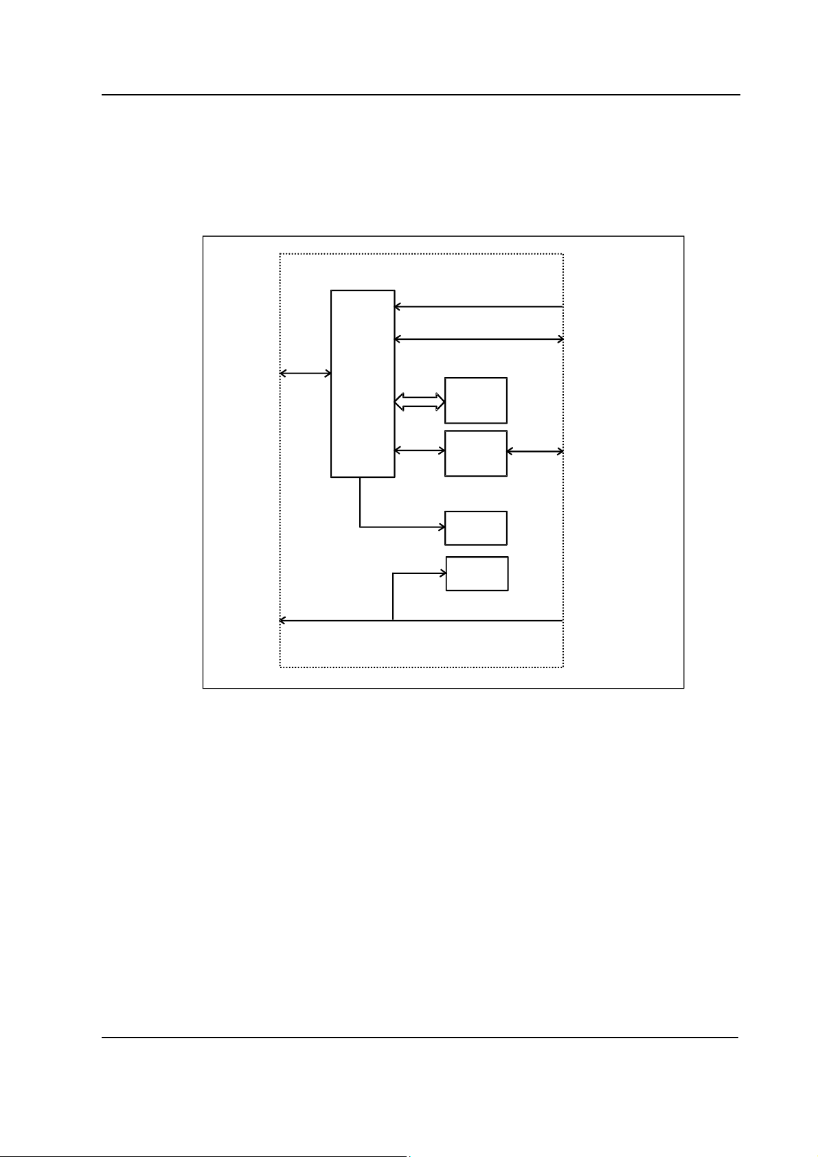
2.1 Command Boards, K-ANE/K-ICU and Command Bars, K-ANEB/ K-ICUB
KEYBOARD PCB
X2
COMWHEEL
X5
5 PIN DIN (D-LCC10)
CONNECTOR
DISPLAY
CONTROLLER
BOARD
X1
RS-232
CPU
PROGRAM
MEMORY
EPROM
DISPLAY
CONTROLLER
BOARD
Figure 1 K-ANE/ K-ICU and K-ANEB/K-ICUB block diagram
K-ANE/ K-ICU, K-ANEB/K-ICUB
The Command board/bar consists of 17 direct function keys, ComWheel and ON/STBY switch.
Command Board/Bar PCB
The PCB is located inside the Command Board/Bar.The board reads the status of the front panel
keys and the ComWheel and forwards the information to the CPU board.
KEYBOARD
SCANNING
CIRCUIT
ALARM
LEDS
STBY
LED
X4
KEYBOARD
ON/STBY
SWITCH
External communication
Communication with the host processor takes place in RS232 serial communication channels
which are available in both the CPU bus and the module bus. Two signals, TXD and RXD, are in use.
No handshaking is used. The 26-pin subminiature D-connector of the Command Board/Bar is
connected to a Display controller board. Serial communication speed rate is 19.2 kbps.
ComWheel
The ComWheel on the front panel is used for menu selection.
3
Document No. 8001589 -1
Page 8
S/5 Keyboards
LEDs
The alarm LEDs are activated by the Command Board/Bar PCB under the commands received via
serial communication from the CPU board. The red or yellow alarm LED is lit when red or yellow
alarm is activated. STBY -led is lit when the device is turned to stand-by and connected to mains.
NOTE: If there are two Command Boards/Bars connected to the system, the system is ON (STBY
LED not lit), when at least one of the switches is positioned ON.
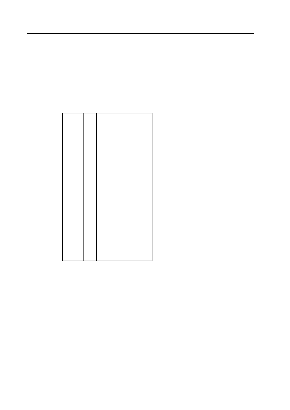
2.1.1 Connectors and signals
26-pin D-connector on K-ANE/K-ICU and K-ANEB/K-ICUB
Pin No I/O Signal
1
2
3
4
5
6
7
8
9
10
11
12
13
14
15
16
17
18
19
20
21
22
23
24
25
26
I
I
O
O
I
Not connected
Not connected
Not connected
Not connected
Not connected
GND
Not connected
Not connected
Not connected
Not connected
Not connected
Not connected
Not connected
N ot connected
+5 V
ON/STBY
Not connected
Not connected
TXDD RS232
RXDD RS232
Not connected
Not connected
Not connected
Not connected
Not connected
Not connected
4
Document No. 8001589-1
Page 9

2.2 Remote Controller, K-REMCO
The Remote Controller consists of 12 direct function keys and the ComWheel.
K-REMCO PCBs
The K-REMCO has two PCBs located inside the Remote Controller. One board has only the
pushbutton switches of the keys. The other board reads the status of the keys and the ComWheel
and forwards the information to the CPU board.
External communication
K-REMCO with standard cable:
Communication with the host processor takes place in RS232 serial communication channels
which are available in both the CPU bus and the module bus. Two signals, TXD and RXD, are in use.
No handshaking is used. The 26-pin subminiature D-connector of the Remote Controller is
connected to a Display controller board. Serial communication speed is 19.2 kbps.
K-REMCO with optional Remote Controller - Compact Monitor cable:
The Compact Monitor or LCD display, D-LCC10A/W converts the communication to RS232 format
(see above).
ComWheel
The ComWheel is used for menu selection.
Command Boards / Bars, Remote Controller
Document No. 8001589 -1
5
Page 10
S/5 Keyboards
3 SERVICE PROCEDURES
3.1 General service information
Field service is limited to replacing faulty PC boards or mechanical parts. The PC boards are then
returned to Datex-Ohmeda for repair.
Datex-Ohmeda Technical Services is always available for service advice. Please provide the unit
serial number, full type designation and a detailed description of the fault.
CAUTION The tests and repairs outlined in this section should only be attempted by trained
personnel with the appropriate equipment. Unauthorized service may void warranty
of the unit.
3.2 Service check
These instructions include complete procedures for a service check. The service check is
recommended to be performed after any service repair. However, the service check procedures can
also be used for determining possible failures.
The procedures should be performed in ascending order.
The instructions include a check forms (Appendix A-B) which should be filled in when performing
the procedures.
The mark
the procedure.
The procedures are designed for monitors with S/5 monitor software of revision 01. However, most
of the procedures also apply to monitors, which contain some other monitor software
type/revision.
? in the instructions means that the check form should be signed after performing
3.2.1 Recommended tools
Tool Order No. Notes
• Central Unit • •
• Screwdriver • •
3.2.2 Command Board, K-ANE/K-ICU and Command Bar, K-ANEB/K-ICUB
• Turn the monitor to STBY.
1. Disconnect the command board cable from the display controller board.
Check that the connector pins of the cable are clean, straight and at about the same height.
Check that the cable is intact. Check that the locking screws inside the connector case are
intact.
6
Document No. 8001589-1
Leave the cable disconnected.
?
Page 11

Command Boards / Bars, Remote Controller
2. Check that the plastic front cover and the front panel sticker are intact.
?
3. Check that the ComWheel cover is intact and is attached properly.
?
4. Check that the ON/STBY -switch and its protector (in K-ANE/K-ICU) are intact and are
attached properly. Check that the ON/STBY -switch changes its state firmly when turning it
back and forth. Leave the switch into STBY -position.
?
5. Reconnect and lock the command board/bar cable to the display controller board.
Check that the stand-by LED is lit up (the Central Unit power cord is connected to the mains).
?
• Turn the monitor on and enter the service menu:
Monitor Setup - Install/Service (password 16-4-34) - Service (password 26-23-8)
6. Take down the information regarding keyboard software.
?
7. Select the menu KEYBOARD with the ComWheel.
Highlight the text UPPER LED. Check that the red alarm LED is turning on and off when
pressing the ComWheel. Check also the yellow alarm LED by selecting LOWER LED from the
menu.
?
8. Check the membrane keys.
Press the keys one by one. Check that each key generates a sound from the loudspeaker and
the corresponding text in the menu changes from yellow to red.
?
9. Check the ComWheel.
Turn the ComWheel clockwise and counterclockwise and check that each step generates a
sound and the corresponding values at the bottom of the menu increase.
Select DUMMY PRESS. Press the ComWheel and check that the press generates a sound and
the corresponding value in the menu increases.
?
10. Perform electrical safety check and leakage current test.
?
7
Document No. 8001589 -1
Page 12

S/5 Keyboards
11. Check that the Command Board/Bar functions normally after the performed electrical safety
check.
?
12. Clean the the Command Board/Bar.
?
• Fill in all necessary documents.
3.2.3 Remote Controller, K-REMCO
• Turn the monitor to STBY.
• Disconnect the remote controller cable from the display controller board.
• Detach the remote controller upper cover and the keypad cover by removing the screws (7
pcs) from the bottom.
1. Check internal parts:
− cables are connected properly
− the remote controller cable is fastened to the bottom cover with screws
− the keypad switches are intact
− the software EPROM under the keypad is attached properly
?
2. Check external parts:
− the upper and bottom covers are intact
− the keypad cover is intact
− the ComWheel cover is intact and is attached properly
?
• Reassemble the remote controller.
3. Check the remote controller cable:
− the cable is intact
8
Document No. 8001589-1
− the cable connector is intact
− the connector pins are clean, straight and at about the same height
− the locking screws inside the connector case are intact
?
• Reconnect the cable to the display controller board and turn the monitor on.
Page 13

Command Boards / Bars, Remote Controller
4. Wait until normal monitoring screen appears, then check that the picture on the screen is
displayed with correct resolution.
If the resolution is not correct, replace the remote controller cable.
?
5. Enter the service menu:
Menu (on the remote controller keypad) - Monitor Setup - Install/Service (password 16-
4-34) - Service (password 26-23-8)
Take down the information regarding remote controller software.
?
• Select the menu KEYBOARD:
Service - Keyboard
6. Check the remote controller keys.
Press the keys one by one. Check that each key generates a sound from the loudspeaker.
?
7. Check the ComWheel.
Turn the ComWheel clockwise and counterclockwise and check that each step generates a
sound and the corresponding values at the bottom of the menu increase.
Select DUMMY PRESS. Press the ComWheel and check that the press generates a sound and
the corresponding value in the menu increases.
?
8. Perform electrical safety check and leakage current test.
?
9. Check that the remote controller functions normally after the performed electrical safety
check.
?
10. Clean the remote controller and the cable.
?
• Fill in all necessary documents.
9
Document No. 8001589 -1
Page 14

S/5 Keyboards
3.3 Disassembly and reassembly
3.3.1 Command Board, K-ANE/ K-ICU
The Command Board is disassembled according to the following procedure. Please refer to the
exploded view of the Command Board.
1. Disconnect the display power cable, the display data cable and the Command Board cable
from the Central Unit.
2. Turn the display on its’ side and loosen the two cross head screws holding the Command
Board to the display screen tray.
3. Lift off the Command Board and pull out the Command Board cable through the slot in the
the display screen tray.
4. Unscrew the two plastic screws holding the front cover of the Command Board to the rear
cover. Carefully remove the rear cover.
5. Disconnect the Command Board cable, the wire set from the ON/STBY switch, the wire set
from the ComWheel and the flat cable from the membrane keyboard.
6. Detach the Command Board PCB by pressing the two plastic fasteners holding the PCB in
place and simultaneously lifting off the PCB.
The Command Board is reassembled by reversing the disassembly procedure.
3.3.2 Command Board, K-ANEB/ K-ICUB
The Command Bar is disassembled according to the following procedure. Please refer to the
exploded view of the Command Bar.
1. Disconnect the Command Bar cable from the Central Unit.
2. Remove the Command Bar from the display unit .
3. Unscrew the three screws holding the front cover of the Command Bar to the rear cover.
Carefully remove the rear cover.
4. Disconnect the Command Bar cable, the wire set from the ON/STBY switch, the wire set from
the ComWheel (K-ANEB, K-ICUB) and the flat cable from the membrane keyboard (K-ANEB, KICUB).
5. Detach the Command Bar PCB by pressing the two plastic fasteners holding the PCB in place
and simultaneously lifting off the PCB.
The Command Bar is reassembled by reversing the disassembly procedure.
10
Document No. 8001589-1
Page 15

3.3.3 Remote Controller K-REMCO
The Remote Controller is disassembled according to the following procedure. Please refer to the
exploded view of the Remote Controller (chapter 6, spare parts).
1. Disconnect the K-REMCO cable from the Central unit.
2. Pull out the knob of the ComWheel.
3. Open the nut on the shaft of the ComWheel.
4. Open the three cross head screws on the bottom of the K-REMCO.
5. Remove the top cover.
6. Open the four screws on the bottom of the K-REMCO.
7. Remove the keyboard cover.
8. Disconnect the K-REMCO cable and the wire set from the Comwheel.
9. Remove the PCBs.
The Remote Controller is reassembled by reversing the disassembly procedure. In reassembly
remember to put the reinforcing cord of the cable around the screw on the metal bridge before
tightening the screw.
Command Boards / Bars, Remote Controller
11
Document No. 8001589 -1
Page 16

S/5 Keyboards
4 TROUBLESHOOTING
4.1 K-ANE/ K-ICU/ K-ANEB/ K-ICUB/ K-REMCO
See Keyboard Service Menu in chapter 5, and perform tests available. If any of the tests fail, see
explanation below.
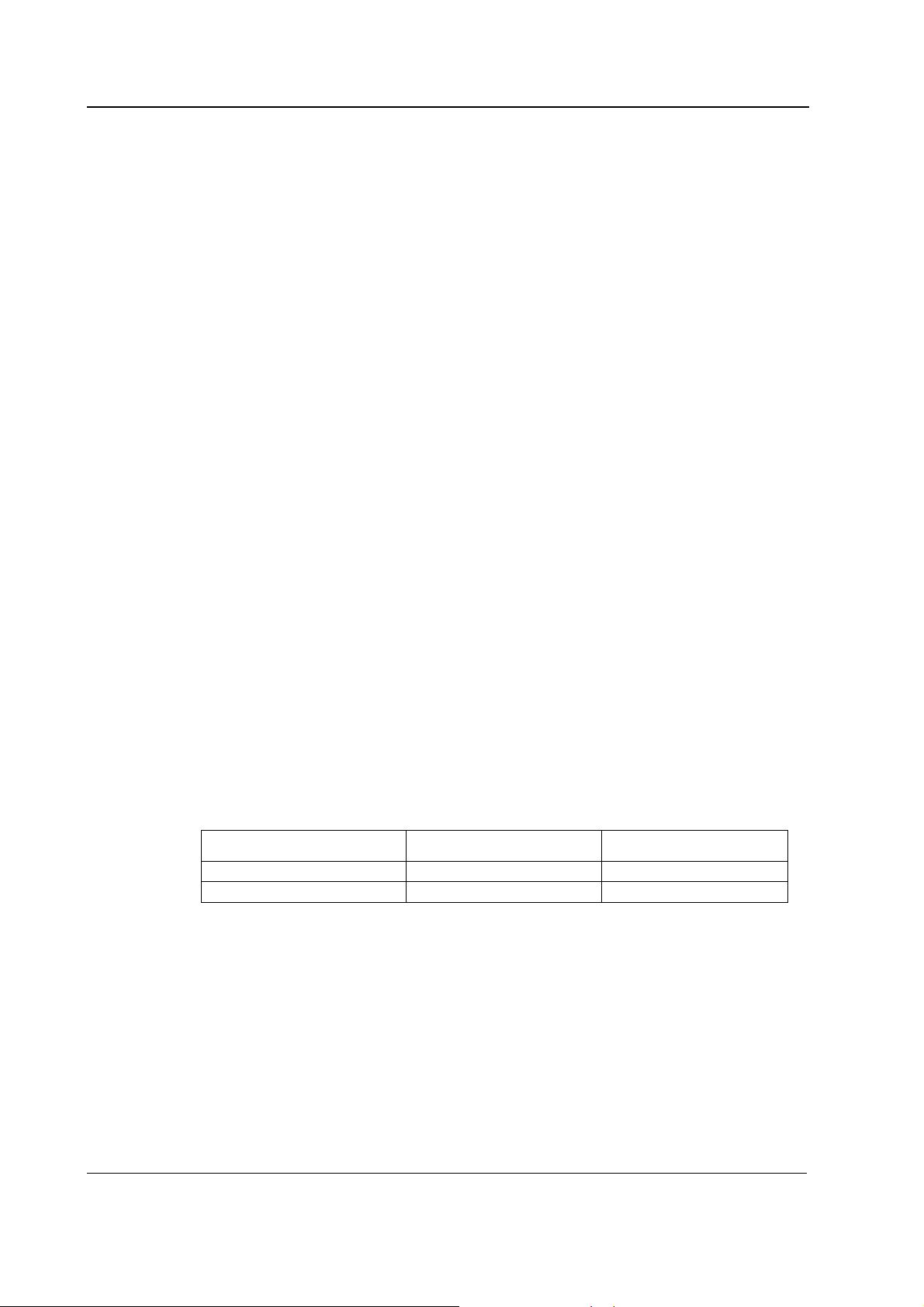
Problem Cause Treatment
ON/STBY switch not working
ComWheel not working
Membrane key not working
Keyboard cable loose or broken. D-26
connector pin failure. Switch leads
broken. Switch connector loose. Switch
faulty
ComWheel leads broken or connector
loose. ComWheel faulty.
Switch cable loose or broken. Keyboard
cable loose or broken. D-26 connector
pin failure. RS232 communication
failure on CPU board
Check the items. Replace them if necessary
Check the items. Replace the ComWheel if
necessary
Check the items. Replace them if necessary.
12
Document No. 8001589-1
Page 17

5 SERVICE MENU
Command Boards / Bars, Remote Controller
1. Press the Monitor Setup key.
2. Select Install/Service (password 16-4-34).
3. Select Service (password 26-23-8) - Keyboard.
13
Document No. 8001589 -1
Page 18

S/5 Keyboards
5.1 Keyboard menu
The service menu for testing the command board
functions.
Upper Led is for testing the upper alarm LED (red) on the
command board. When the text is highlighted, the upper
alarm LED can be turned on and off by pressing the
ComWheel.
Lower Led is for testing the lower alarm LED (yellow) on
the command board. When the text is highlighted, the
lower alarm LED can be turned on and off by pressing the
ComWheel.
Dummy Press is for testing the ComWheel. When the text
is highlighted, pressing of the ComWheel create a sound
from the loudspeaker and the corresponding number on
the service data field increase.
Service Data
Message count counts the number of messages that are
sent out to the main CPU board.
Leds upper and lower indicate the states of the alarm
LEDs on the command board.
Direct action keys texts are indications to the command
board membrane keys. When a key on the command
board is pressed, the corresponding text in the menu
changes its colour.
Control wheel, Press counts the ComWheel pressings.
Control wheel, Clockwise and Counterclockwise the
ComWheel turnings.
Since shows the date and the time of the last run time
reset.
5.1.1 Keyboard Log
All the keyboard presses and the commands given by the
ComWheel are recorded in the Keyboard Log. The
keyboard log is saved in the permanent memory of the
monitor. The length of the log is 1150 events. The log is
FIFO type.
14
Document No. 8001589-1
Page 19

5.1.2 Keyboard Type
Store Mask A selection for setting the anaesthesia
keyboard’s language. The selected language determines
the outcome of the lower keypad.
Store Type is for setting the keyboard’s type;
COM = Command Board
ARK = Anaesthesia Keyboard
AIC = Information Center Keyboard
NOTE: The settings should be checked if the
controller board is replaced. If settings are
changed, the new settings will not be valid until
the next start-up.
Command Boards / Bars, Remote Controller
15
Document No. 8001589 -1
Page 20

S/5 Keyboards
6 SPARE PARTS
NOTE: Only changed part numbers are listed under later revisions. To find the desired part: check
first the list of the revision that corresponds your device. If the part is not listed there, check the
previous revision, etc. until you find the right number.
* this part is recommended for stock
Item numbers refer to the exploded view.
6.1 Command Board, K-ANE, K-ICU
6.1.1 Command Board, K-ANE, K-ICU Rev. 00
Item Item description Order No.
2 Command board cable, K-VHC14 (Rev.02) *(883229) Use 893945
3 Command board PC board, K-VCH14, K-VNC15 *(883228) Use 893943
5 Plastic front cover, K-VHC14 (Rev. 02), K-VNC15 883178
6 Keyboard membrane, AS/3 AM/CM 879373
7 ON/STBY switch protector 881431
8 ComWheel cover and spring 879191
13 ON/STBY switch *879871
14 Rotary wheel 879872
16 Plastic rear cover, K-VHC14 (Rev. 02) 883177
17 Insulation plate 883963
18 Bushing 25x6.5, M3 640446
16
Document No. 8001589-1
Page 21

Command Boards / Bars, Remote Controller
6.1.2 Command Board, K-ANE, K-ICU Rev. 01
Item Item description Order No.
2 Command board cable, K-ANE/ICU/BLANK *893945
3 Command board PC board, K-ANE/ICU, D-LCC10 *893943
5 Plastic front cover, K-ANE/ICU/BLANK (Rev. 01) 892812
16 Plastic rear cover, K-ANE/ICU /BLANK (Rev. 01) 892811
6.2 Command Bar, K-ANEB, K-ICUB Rev.00
6.2.1 Command Board, K-ANEB, K-ICUB Rev. 00
Item Item description Order No.
1 ComWheel 898794
2 Membrane keypad 898255
3 Front cover 897980
4 EMC plate 8000225
5 Switch cover 640453
6 ON/STBY-switch 8001395
7 Command board PC board 898007
8 Rotary switch, opto-encoder 113291
9 Closing cover 897983
10 Back cover 897981
11 Command bar cable 898283
12 Cable plate 897982
17
Document No. 8001589 -1
Page 22

S/5 Keyboards
6.3 Blank Command Board, K-BLANK
6.3.1 Blank Command Board, K-BLANK Rev. 00
Item Item description Order No.
2 Command board cable, K-VHC14 (Rev.02) *(883229) Use 893945
3 Command board PC board, K-VCH14, K-VNC15 (883228) Use 893943
5 Plastic front cover, K-VHC14 (Rev. 02), K-VNC15 883178
7 ON/STBY switch protector 881431
13 ON/STBY switch *879871
16 Plastic rear cover, K-VHC14 (Rev. 02) 883177
17 Insulation plate 883963
18 Bushing 25x6.5, M3 640446
19 Fitting plate, K-BLANK 892335
6.3.2 Blank Command Board, K-BLANK Rev. 01
Item Item description Order No.
2 Command board cable, K-ANE/ICU/BLANK *893945
3 Command board PC board, K-ANE/ICU, D-LCC10 *893943
5 Plastic front cover, K-ANE/ICU/BLANK (Rev. 01) 892812
16 Plastic rear cover, K-ANE/ICU /BLANK (Rev. 01) 892811
18
Document No. 8001589-1
Page 23

6.4 Remote Controller, K-REMCO
Command Boards / Bars, Remote Controller
6.4.1 Remote Controller, K-REMCO Rev. 00
Item Item description Order No.
1 CPU board, K-REMCO *890368
2 Keyboard PCB, K-REMCO 890371
3 Connecting plate 891427
4 Rotary wheel 891036
5 ComWheel cover 891423
6 Plastic rear cover, K-REMCO 891421
7 Plastic front cover, K-REMCO 891422
8 Remote controller cable, K-REMCO *891813
9 Bridge for cable 893235
11 Front panel framework 891426
12 Slotted recess screw M2.5x22 61218
13 Cross recess screw M2.5x16 628719
14 Cross recess screw M3x6 61721
15 Star washer 63611
16 Cable binder 546454
19
Document No. 8001589 -1
Page 24

S/5 Keyboards
6.4.2 Remote Controller, K-REMCO Rev. 01
Item Item description Order No.
5 ComWheel cover 898940
6 Plastic rear cover, K-REMCO 898939
7 Plastic front cover, K-REMCO 898938
6.4.3 Front panel stickers for K-ANE/ICU/REMCO
K-ANE
Adaptation
(Rev. 00)
Order No.
-23- (Eng) 891663 893069 8000158 891589 893484 8000169
-26- (Fin) 891669 893070 8000165 892324 893490 8000176
-31- (Jpn) 892080 893071 8000692 -- -- 8000693
-33- (Ger) 891664 893072 8000159 892319 893485 8000170
-40- (Spa) 891667 893073 8000162 892322 893488 8000173
-41- (Swe) 891670 893074 8000166 892325 893491 8000177
-42- (Dnk) 892197 893075 8000168 892198 893492 8000179
-43- (Fre) 891665 893076 8000160 892320 893486 8000171
-44- (Dut) 891666 893077 8000161 892321 893487 8000172
-46- (Ita) 891668 893078 8000163 892323 893489 8000174
-47- (Nor) -- 893550 8000167 -- 893563 8000178
-48-(Por) -- -- 8000164 -- -- 8000175
K-REMCO
Adaptation
(Rev. 00)
Order No.
-23- (Eng) 891425 891425
-26- (Fin) 892317 892317
-31- (Jpn) -- 894962
-33- (Ger) 892312 892312
-40- (Spa) 892315 892315
-41- (Swe) 892318 892318
-42- (Dnk) 892203 892203
-43- (Fre) 892313 892313
-44- (Dut) 892314 892314
-46- (Ita) 892316 892316
-47- (Nor) 893553 893553
-48-(Por) 895233
K-ANE
(Rev. 01)
Order No.
K-REMCO *
(Rev. 01)
Order No.
K-ANE *
(Rev. 02)
Order No.
K-ICU
(Rev. 00)
Order No.
K-ICU
(Rev. 01)
Order No.
K-ICU *
(Rev. 02)
Order No.
20
Document No. 8001589-1
* NOTE: S/5 stickers
Page 25

6.4.4 Front panel stickers for K-ANEB/ICUB
Command Boards / Bars, Remote Controller
K-ANEB
Adaptation
(Rev. 00)
Order No.
..00..DA 898093 898105
..00..DE 898084 898096
..00..EN 898083 898095
..00..ES 898087 898099
..00..FI 898090 898102
..00..FR 898085 898097
..00..IT 898088 898100
..00..JA 898094 898106
..00..NL 898086 898098
..00..NO 898092 898104
..00..PT 898089 898101
..00..SV 898091 898103
K-ICUB
(Rev. 00)
Order No.
21
Document No. 8001589 -1
Page 26

S/5 Keyboards
7 EARLIER REVISIONS
For more service information on the earlier revisions, please refer to:
Command Board revision 01 Service Manual p/n 880850
Command Board revision 02 Service Manual p/n 885930
This manual supports all later revisions.
22
Document No. 8001589-1
Page 27

Appendices A, B, Service check forms, K-ANE/ICU, K-ANEB/ICUB, K-REMCO
APPENDICES A, B
23
Document No. 8001589 -1
Page 28

S/5 Keyboards
24
Document No. 8001589-1
Page 29

Appendices A, B, Service check forms, K-ANE/ICU, K-ANEB/ICUB, K-REMCO
A
Service check form Command Board, K-ANE/K-ICU, Command Bar, K-ANEB/K-ICUB
Customer
Service
Service engineer Date
OK = Test OK N.A. = Test not applicable Fail = Test Failed
OK N.A. Fail OK N.A. Fail
1. Cable 2. Front cover and front
3. ComWheel cover 4. ON/STBY -switch and
Notes
5. Stand by -LED
6. Command board
software
7. Alarm LEDs 8. Membrane keys
KB
Keyboard type S/N
panel sticker
protector
9. ComWheel
Notes
10. Electrical safety check 11. Functioning after
electrical safety check
12. Final cleaning
Notes
Used Spare Parts
Signature
-1(1)
Document No. 8001589 -1
Page 30

S/5 Keyboards
2
Document No. 8001589-1
Page 31

Appendices A, B, Service check forms, K-ANE/ICU, K-ANEB/ICUB, K-REMCO
Service check form Remote Controller, K-REMCO
Customer
Service
Service engineer Date
OK = Test OK N.A. = Test not applicable Fail = Test Failed
OK N.A. Fail OK N.A. Fail
1. Internal parts 2. External parts
3. Cable 4. Monitor picture
Notes
5. Stand by -LED
6. Command board
software
7. Alarm LEDs 8. Membrane keys
KB
Keyboard type S/N
9. ComWheel
Notes
10. Electrical safety check 11. Functioning after
electrical safety check
12. Final cleaning
Notes
Used Spare Parts
Signature
B-1(1)
Document No. 8001589 -1
Page 32

S/5 Keyboards
2
Document No. 8001589
 Loading...