


S/M No. : R637V0S001
Service Manual
Microwave Oven
Model: KOR-637V0S
KOR-633V0S
Caution
:In this Manual, some parts can be changed for improving, their performance without notice in the parts list. So, if you need the latest parts information,please refer to PPL(Parts Price List) in Service Information Center (http://svc.dwe.co.kr).
DAEWOO ELECTRONICS CO., LTD.
http : //svc.dwe.co.kr |
Jan. 2002 |

PRECAUTIONS TO BE OBSERVED BEFORE AND DURING SERVICING TO AVOID POSSIBLE EXPOSURE TO EXCESSIVE MICROWAVE ENERGY
(a)Do not operate or allow the oven to be operated with the door open.
(b)Make the following safety checks on all ovens to be serviced before activating the magnetron or other microwave source, and make repairs as necessary: (1) Interlock operation, (2) Proper door closing, (3) Seal and sealing surfaces (arcing, wear, and other damage), (4) Damage to or loosening of hinges and latches, (5) Evidence of dropping or abuse.
(c)Before turning on power to the microwave oven for any service test or inspection within the microwave generating compartments, check the magnetron, wave guide or transmission line, and cavity for proper alignment, integrity, and connections.
(d)Any defective or misadjusted components in the interlock, monitor, door seal, and microwave generation and transmission systems shall be repaired, replaced, or adjusted by procedures described in this manual before the oven is released to the owner.
(e)A microwave leakage check to verify compliance with the Federal performance standard should be performed on each oven prior to release to the owner.
TABLE OF CONTENTS |
|
SAFETY AND PRECAUTIONS ........................................................................................................................................... |
2 |
FOR SAFE OPERATION ...................................................................................................................................... |
2 |
FOR SAFE SERVICE PROCEDURES ................................................................................................................. |
2 |
SPECIFICATIONS ............................................................................................................................................................... |
3 |
EXTERNAL VIEW................................................................................................................................................................ |
4 |
OUTER DIMENSION............................................................................................................................................. |
4 |
FEATURE DIAGRAM ............................................................................................................................................ |
5 |
CONTROL PANEL ................................................................................................................................................ |
6 |
INSTALLATION ................................................................................................................................................................... |
8 |
OPERATIONS AND FUNCTIONS....................................................................................................................................... |
9 |
IMPORTANT SAFETY INSTRUCTIONS FOR STERILIZATION ...................................................................................... |
10 |
DISASSEMBLY AND ASSEMBLY.................................................................................................................................... |
11 |
INTERLOCK MECHANISM AND ADJUSTMENT............................................................................................................. |
21 |
TROUBLE SHOOTING GUIDE ......................................................................................................................................... |
22 |
MEASUREMENT AND TEST ............................................................................................................................................ |
27 |
MEASUREMENT OF THE MICROWAVE POWER OUTPUT ............................................................................ |
27 |
MICROWAVE RADIATION TEST ....................................................................................................................... |
28 |
COMPONENT TEST PROCEDURE ................................................................................................................... |
29 |
WIRING DIAGRAM............................................................................................................................................................ |
30 |
PRINTED CIRCUIT BOARD.............................................................................................................................................. |
31 |
CIRCUIT CHECK PROCEDURE ........................................................................................................................ |
31 |
PCB CIRCUIT DIAGRAM.................................................................................................................................... |
35 |
P.C.B. LOCATION NO ........................................................................................................................................ |
36 |
EXPLODED VIEW AND PARTS LIST............................................................................................................................... |
37 |
DOOR ASSEMBLY ............................................................................................................................................. |
37 |
CONTROL PANEL ASSEMBLY.......................................................................................................................... |
37 |
TOTAL ASSEMBLY............................................................................................................................................. |
37 |
1

SAFETY AND PRECAUTIONS
1. FOR SAFE OPERATION
Damage that allows the microwave energy (that cooks or heats the food) to escape will result in poor cooking and may cause serious bodily injury to the operator.
IF ANY OF THE FOLLOWING CONDITIONS EXIST, OPERATOR MUST NOT USE THE APPLIANCE. (Only a trained service personnel should make repairs.)
(1)A broken door hinge.
(2)A broken door viewing screen.
(3)A broken front panel, oven cavity.
(4)A loosened door lock.
(5)A broken door lock.
The door gasket plate and oven cavity surface should be kept clean.
No grease, soil or spatter should be allowed to build up on these surfaces or inside the oven. DO NOT ATTEMPT TO OPERATE THIS APPLIANCE WITH THE DOOR OPEN.
The microwave oven has concealed switches to make sure the power is turned off when the door is opened. Do not attempt to defeat them.
DO NOT ATTEMPT TO SERVICE THIS APPLIANCE UNTIL YOU HAVE READ THIS SERVICE MANUAL.
2.FOR SAFE SERVICE PROCEDURES
1.If the oven is operative prior to servicing, a microwave emission check should be performed prior to servicing the oven.
2.If any certified oven unit is found to servicing, a microwave emission check should be performed prior to servicing the oven.
(a)inform the manufacturer, importer or assembler,
(b)repair the unit at no cost to the owner,
(c)attempt to ascertain the cause of the excessive leakage,
(d)tell the owner of the unit not to use the unit until the oven has been brought into compliance.
3.If the oven operates with the door open, the service person should tell the user not to operate the oven and contact the manufacturer and CDRH immediately.
IMPORTANT
The wire in this mains lead coloured in accordance with the following code.
Green-and-yellow : Each
Blue |
: Neutral |
Brown |
: Live |
As the colours of the wires in the manins lead of this appliance may not correspond with the coloured markings identifying the terminals in your plug, proceed as follows.
The wire which is coloured green-and-yellow must be connected to the terminal in the plug which is marked with the letter ‘E’, earth symbol or coloured green-and-yellow.
The wire which is coloured blue must be connected to the terminal which is marked with the letter ‘N’ or coloured black.
The wire which is coloured brown must be connected to the terminal which is marked with the letter ‘L’ or coloured red.
NOTE
This oven is designed for counter-top use only.
2

SPECIFICATIONS
MODEL |
|
KOR-637V0S |
KOR-633V0S |
|
POWER SUPPLY |
|
120V~60Hz, SINGLE PHASE WITH GROUNDING |
||
|
|
|
|
|
|
|
MICROWAVE |
1,200W |
|
|
|
|
|
|
POWER |
|
GRILL |
|
|
|
|
|
|
|
CONSUMPTION |
|
COMBINATION |
|
|
|
|
|
|
|
|
|
COMBINATION |
10W |
|
|
|
|
|
|
MICROWAVE ENERGY OUTPUT |
800W |
|||
|
|
|
|
|
MICROWAVE FREQUENCY |
2450MHz |
|||
|
|
|
|
|
OUTSIDE DIMENSIONS (W x H x D) |
465 x 279 x 360 mm (18.3 x 11.0 x 14.2 in) |
465 x 279 x 365 mm (18.3 x 11.0 x 14.4 in) |
||
|
|
|
|
|
CAVITY DIMENSIONS (W x H x D) |
290 x 220 x 306 mm (11.4 x 8.7 x 12.0 in) |
|||
|
|
|
|
|
NET WEIGHT |
|
APPROX. 12.3kg (27.2 Ibs.) |
||
|
|
|
|
|
TIMER |
|
59 MIN. 00 sec. |
||
|
|
|
|
|
FUNCTION SELECTIONS |
|
MICROWAVE |
||
|
|
|
|
|
POWER SELECTIONS |
|
5 LEVELS |
||
|
|
|
|
|
CAVITY VOLUME |
|
0.7 Cu. Ft. |
||
|
|
|
|
|
* SPECIFICATIONS ARE SUBJECT TO CHANGE WITHOUT NOTICE.
3
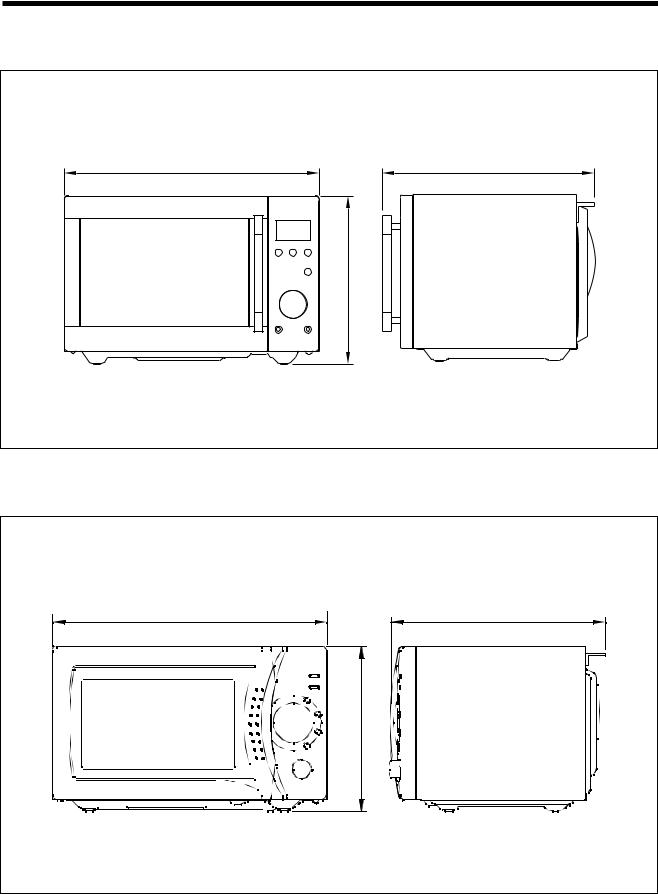
EXTERNAL VIEW
1. OUTER DIMENSION |
|
(1) KOR-637V0S |
|
465 |
360 |
|
279 |
(2) KOR-633V0S |
|
465/495 |
365/392 |
|
279/294 |
|
4 |
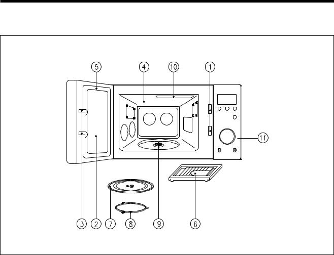
2. FEATURE DIAGRAM
1 SAFETY INTERLOCK SYSTEM
2DOOR SCREEN
Allows viewing of food. The screen is transparent to light, but prevents microwaves escaping.
3DOOR LATCH
When the door is closed, it will automatically shut off. If the door is opened while the oven operating, the magnetron tube will immediately stop operating.
4 OVEN CAVITY
5DOOR SEAL
Door seal surfaces prevent microwave escaping from the oven cavity.
7GLASS COOKING TRAY
Made of special heat resistant glass. The tray can be easily removed for cleaning. Make sure it is correctly positioned(indentation) before operating. Place food in a suitable container(dish ) on the tray.
8ROLLER GUIDE
Supports the glass cooking tray.
9COUPLER
This fits over the shaft in the center of the ovens cavity floor. This is to remain in the oven for all cooking.
0 UV LAMP
q CONTROL PANEL
5
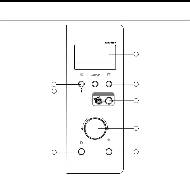
3.CONTROL PANEL
(1)KOR-637V0S
|
M/W DEF. |
LOCK PURIFI |
g |
AUTO COOK |
POWER/ |
CLOCK |
|
|
DEFROST |
|
|
1 |
|
|
|
3 |
|
|
|
1. |
Dinner Plote |
STERILIZATION |
|
2. |
Soup |
|
|
3. |
Beverage |
|
|
4. |
Fresh Vegetable |
|
|
5
4
2
|
h |
ig |
|
e |
|
W |
|
t
/
T
i
m
e
|
8 |
|
START/ |
STOP/CLEAR |
EASY COOK |
6 |
7 |
1AUTO COOK
Used to cook using a program or to reheat.
2STERILIZATION
Used to sterilize baby bottle, cup, plate, etc.
3POWER/DEFROST
Used to set power level and to defrost foods by weight or time.
4CLOCK
Used to set clock.
5DISPLAY
Cooking time, power level, indicators and present time are displayed.
6STOP/CLEAR
Used to stop the oven operation or to erase all entries.
7START/EASY COOK
Used to start the oven operation and also increase the reheat time by 30 seconds.
8DIAL KNOB
Used to set the time and weight.
6
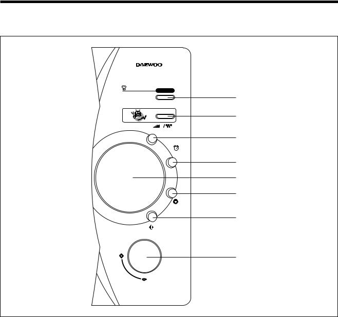
(2) KOR-633V0S
KOR-633V
AUTO COOK
1.Dinner Plate
2.Soup
3.Beverage
4.Fresh Vegetable
STERILIZATION
POWER/DEF.
CLOCK
M/W DEF. LOCK STERIL. g
STOP/
CLEAR
START/
EASY COOK
Weight/
Time
1
2
3
4
5
6
7
8
1AUTO COOK
Used to cook using a program or to reheat.
2STERILIZATION
Used to sterilize baby bottle, cup, plate, etc.
3POWER/DEF.
Used to set power level and to defrost foods by weight or time.
4CLOCK
Used to set clock.
5DISPLAY
Cooking time, power level, indicators and present time are displayed.
6STOP/CLEAR
Used to stop the oven operation or to erase all entries.
7START/EASY COOK
Used to start the oven operation and also increase the reheat time by 30 seconds.
8DIAL KNOB
Used to set the time and weight.
7

INSTALLATION
1. Steady, flat location.
This microwave oven should be set on a steady, flat surface.
This microwave oven is designed for counter top use only.
2. Leave space behind and side.
All air vents should be kept a clearance. If all vents are covered during operation, the oven may overheat and, eventually, cause failure.
3. Away from radio, and TV sets
Poor television reception and radio interference may result if the oven is located close to a TV, radio, antenna, or feeder and so on. Position the oven as far from them as possible.
4. Away from heating appliances and water taps
Keep the oven away from hot air, steam or splash when choosing a place to position it, or the insulation might be adversely affected and breakdowns occur.
5.Power supply
•Check your local power source.
This microwave oven requires a current of approximately 6 amperes, 230 Volts, 50 Hz.
•Power supply cord is about 0.8 meters long.
•The voltage used must be the same as specified on this oven. Using a higher voltage may result in a fire or other accident causing oven damage. Using low voltage will cause slow cooking. We are not responsible for damage resulting from use of this oven with a voltage of ampere fuse other than those specified.
•This appliance is supplied with cable of special type, which, if damaged, must be repaired with cable of same type.
Such a cable can be purchased from DAEWOO and must be installed by a Qualified Person.
6.Examine the oven after unpacking for any damage such as:
A misaligned door, broken door or a dent in cavity.
If any of the above are visible, DO NOT INSTALL, and notify dealer immediately.
7. Do not operate the oven if it is colder than room temperature
(This may occur during delivery in cold weather.) Allow the oven to become room temperature before operating.
EARTHING INSTRUCTIONS
This appliance must be earthed. In the event of an electrical short circuit, earthing reduces the risk of the electric shock by providing an escape wire for the electric current. This appliance is equipped with a cord having a earthing plug. The plug must be plugged into an outlet that is properly installed and earthed.
WARNING
Improper use of the earthing plug can result in a risk of electric shock. Consult a qualified electrician or serviceman if the earthing instructions are not completely understood, or if doubt exists as to whether the appliance is properly earthed, and either : If it is necessary to use an extension cord, use only a 3-wire extension cord that has a 3-blade earthing plut, and a 3-slot receptacle that will accept the plug on the appliance. The marked rating of the extension cord should be equal to or greater than the electrical rating of the appliance, or Do not use an extension cord.
8

OPERATIONS AND FUNCTIONS
1.Connect the main lead to an electrical outlet.
2.After placing the food in a suitable container, open the oven door and put it on the glass tray. The glass tray must always be in place during cooking.
3.Close the door securely.
4.When the oven door is opened, the light turns off.
5.The oven door can be opened at any time during operation by touching the door release button on the control panel. The oven will automatically shut off. To restart the oven, close the door and then press START button.
6.Each time a button is pressed, a BEEP will sound to acknowledge the touch.
7.The oven automatically cook on full power unless set to a lower power level.
8.The display will show : 0 when the oven is plugged in.
9.Time clock returns to the present time when the cooking time ends.
10.When the STOP/CLEAR buttion is pressed during the oven operation, the oven stops cooking and all information retained.
To erase all information (except the present time), press the STOP/CLEAR button once more. If the oven door is opened during the oven operation, all information is retained.
11.If the START buttion is pressed and the oven does not operate, check the area between the door and door seal for obstructions and make sure the door is closed securely. The oven will not start cooking under the door is completely closed or the program has been reset.
12.When using the STERILIZATION mode:
•After sterilize metal tablewares, take out them certainly. If not so, pressing other buttons it can be happened to spark.
•Do not use the glass tray only for the STERILIZATION mode.
Make sure the oven is properly installed and plugged into the electrical outlet.
Wattage output chart
The power level is set by pressing the POWER/DEFROST button. The chart shows the display, the power level and the percentage of power.
Press POWER/DEFROST |
Power level(Display) |
Approximate Percentage of Power |
|
|
|
Once |
P-HI |
100% |
|
|
|
Twice |
P-80 |
80% |
|
|
|
3 times |
P-60 |
60% |
|
|
|
4 times |
P-40 |
40% |
|
|
|
5 times |
P-20 |
20% |
|
|
|
9
IMPORTANT SAFETY INSTRUCTIONS FOR STERILIZATION
1.Do not use the oven for the food.
2.Caution: Surface of utensil, tableware, etc., must be directly exposed to UV light for effective sterilization. The ultraviolet ray can’t penetrate through the materials such as glass, metal and plastic.
3.For proper sterilization, utensils and cookware must be properly cleaned/washed before sterilizing.
4.Do not expose skin or eyes to UV radiation, excessive exposure may cause injury to skin or eyes.
5.UV lamp is only to be replaced by the type identified and by a properly trained service personnel.
6.Additional instructions may be required based on experience resulting from conduct of efficacy testing.
7.Do not use the oven for the medical use.
STERILIZATION
This function allow you to sterilize tableware.
For proper sterilization, utensils and cookware must be properly cleaned/washed before sterilizing.
Place the shelf on the glass cooking tray. Be repeatedly pressing STERILIZATION button, you can extend sterilizing time from 3 minutes to 30 minutes. (3, 5, 10, 20, 30 minutes)
STERILIZATION
1. Press STERILIZATION button. |
When you press STERILIZATION button, "3:00" appears. |
|
After 1.5 seconds, the oven starts sterilizing and STERIL |
|
indicator starts blinking to show the oven is Sterilization |
|
mode. The display counts down the time to show you how |
|
much sterilizing time is left in the Sterilization mode. |
NOTE: After sterilizing, if you don’t open the door, and press other buttons except STERILIZATION, “door” is displayed and a beep sounds. In this case, when you open and close the door once, oven is operated nomally.
CAUTION: After you sterilize metal tableware, if you don’t take out it and you touch other buttons, it can be happened to spark.
REAR
(INSIDE OF CAVITY)
IN
FRONT (DOOR SIDE)
<STERILIZING TIME>
 OVER 30 MINUTES
 OVER 20 MINUTES
  OVER 10 MINUTES
OVER 3 MINUTES
"ESPECIALLY, PLACE THE BABY BOTTLE HERE."
•These instructions are based on experience resulting from conduct of efficacy testing by using petri dishes.
•The deep shaped utensil such as a feeding bottle shall be needed more sterilizing time than described above diagram.
NOTE:
1.A shelf should be placed during UV-sterilization operation.
2.Do not use the shelf during microwave cooking.
3.For better UV-sterilization, depression shaped utensil such as a feeding bottle or a cup shall be placed on the front area of the shelf.
10
DISASSEMBLY AND ASSEMBLY
Cautions to be observed when trouble shooting.
Unlike many other appliances, the microwave oven is high-voltage, high-current equipment. It is completely safe during normal operation.
However, carelessness in servicing the oven can result in an electric shock or possible danger from a short circuit. You are asked to observe the following precautions carefully.
1.Always remove the power plug from the outlet before servicing.
2.Use an insulated screwdriver and ware rubber gloves when servicing the high voltage side.
3.Discharge the high voltage capacitor before touching any oven components or wiring.
(1)Check the grounding.
Do not operate on a two-wire extension cord.
The microwave oven is designed to be used with earthed.
It is imperative, therefore, to make sure it is earthed properly before beginning repair work.
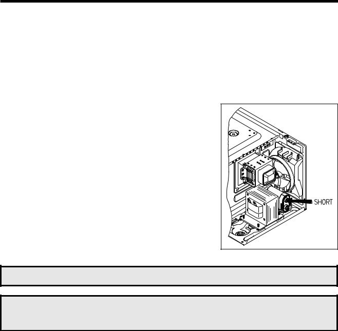
(2) Warning about the electric charge in the high voltage capacitor.
For about 30 seconds after the operation stopped and electric charge remains in the high voltage capacitor.
When replacing or checking parts, short between oven chassis and the negative high terminal of the high voltage capacitor by using a properly insulated screwdriver to discharge.
4. When the 12A fuse is blown out due to the operation of the monitor switch; replace primary interlock switch, secondary interlock switch and interlock monitor switch.
5.After repair or replacement of parts, make sure that the screws are properly tightened, and all electrical connections are tightened.
6.Do not operate without cabinet.
CAUTION : Service personnel should remove their watches whenever working close to or replacing the magnetron.
WARNING : When servicing the appliance, need a care of touching or replacing high potential parts because of electrical shock or exposing microwave. These parts are as follows - HV Transformer, Magnetron, HV Capacitor, HV Diode HV Fuse.
11
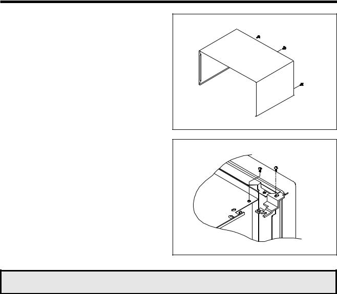
1.To remove cabinet
1)Remove three screws on cabinet back.
2)Push the cabinet backward.
2. To remove door assembly
1) Remove two screws which secure the stopper hinge top.
2)Remove the door assembly from top plate of cavity.
3)Reverse the above for reassembly.
NOTE : After replacing the door assembly, perform a check of correct alignment with the hinge and cavity front plate.
12
Caution: In this Service Manual, some parts can be changed for improving, their performance without notice in the parts list. So, if you need the latest parts information, please refer to PPL(Parts Price List) in Service information Center(http://svc.dwe.co.kr)
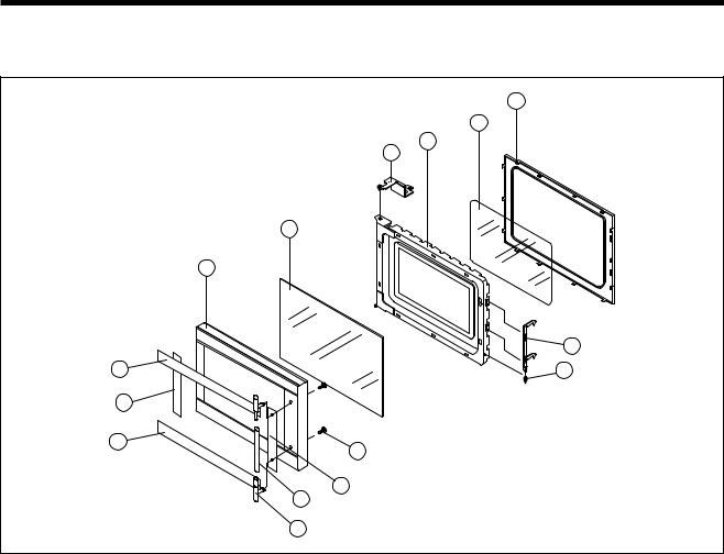
3.To remove door parts.
(1)KOR-637V0S
A06
A05
A04
A03
A02
A01
|
A07 |
A15 |
A08 |
A14
A13
A09
A10
A11
A12
REF NO. |
PART CODE |
PART NAME |
DESCRIPTION |
Q’TY |
REMARK |
A01 |
3512205230 |
FRAME DOOR |
ABS SG-175 SG-0760D |
1 |
|
|
|
|
|
|
|
A02 |
3517005670 |
BARRIER SCREEN *O |
TEMP GLASS T3.2 |
1 |
|
|
|
|
|
|
|
A03 |
3515204100 |
STOPPER HINGE *T AS |
KOR-63150S |
1 |
|
|
|
|
|
|
|
A04 |
3511706120 |
DOOR PAINTING AS |
KOR-634R0S |
1 |
|
|
|
|
|
|
|
A05 |
3517002800 |
BARRIER SCREEN *I |
PET 0.1 |
1 |
|
|
|
|
|
|
|
A06 |
3512300200 |
GASKET DOOR |
PP |
1 |
|
|
|
|
|
|
|
A07 |
3513100730 |
HOOK |
POM BLACK |
1 |
|
|
|
|
|
|
|
A08 |
3515101320 |
SPRING HOOK |
HSW-3 |
1 |
|
|
|
|
|
|
|
A09 |
7112402011 |
SCREW TAPPING |
T1 TRS 4X20 MFZN |
2 |
|
|
|
|
|
|
|
A10 |
3511606100 |
DECORATOR DOOR*R |
STS304 T0.5H/L |
1 |
|
|
|
|
|
|
|
A11 |
3512603220 |
HANDLE DOOR |
CR T0.9 |
1 |
|
|
|
|
|
|
|
A12 |
3515307300 |
SUPPORTER HANDLE |
ABS SG-175 |
2 |
|
|
|
|
|
|
|
A13 |
3511605900 |
DECORATOR DOOR *U |
STS304 T0.5H/L |
1 |
|
|
|
|
|
|
|
A14 |
3511606200 |
DECORATOR DOOR *L |
STS304 T0.5H/L |
1 |
|
|
|
|
|
|
|
A15 |
3511605800 |
DECORATOR DOOR *T |
STS304 T0.5H/L |
1 |
|
|
|
|
|
|
|
13
 Loading...